Embed Size (px)
Citation preview
Excellence Set in Concrete© Page 1 © Wire Reinforcement Institute, Inc.
TF 101-Intro-14
Historical Data on Wire, Triangular Wire Fabric/ Mesh and Welded Wire Concrete Reinforcement
Introduction
To: Architects, Structural Engineers, Contractors and Building Owners
We receive many technical inquiries on old wire spacings, wire sizes and descriptions. Also, many
ask what the physical /mechanical properties are for wire (See p.1). The reprint of old ASTM
Standards and the three tables that follow provide answers to a number of questions often posed. For
example, what is the tensile strength and yield strength of the old wire and WWR? The answer can
be found on Page 1. On Page 2 can be found the table of gauge numbers and the diameters, areas
and weights of wires from 16 gauge to 1/2 inch wires. Page 3 is addressed to triangular mesh (before
welded wire came on the scene) – the table gives style numbers with single wire or bundled wires
that yield the areas of the longitudinal wires (the main or structural wires). Weights per 100 square
feet are also included on Page 3. Triangular wire mesh was only made with longitudinal wires.
Diagonal wires were used at 2, 4 or 8 inches to hold the longitudinal wires in place. If one desired to
have the same wires in the transverse direction (for two-way reinforced slabs) – another sheet was
made and placed on top of the other sheet at 90 degrees. Page 4 contains typical tables of wire
properties similar to the way WWR is described today – however, in those tables gauges were used
and not areas of wire. Those styles were used from 1915 through the 1960’s.
These four pages should answer most questions about old wire and the various styles of WWR or
mesh used in the past. It is always a good idea to take a sample of the wire reinforced concrete to
check or confirm what wire sizes and spacings were used and where it was placed in the concrete.
Many times field changes were made and material that was specified or shown on the plans may have
been changed in the field.
Pages 5-7 tell the story of the history of WWR, followed by a conclusion page, titled “This Modern
Era” - describing where the industry is today.
Excellence Set in Concrete© Page 2 © Wire Reinforcement Institute, Inc.
TF 101-Intro-14
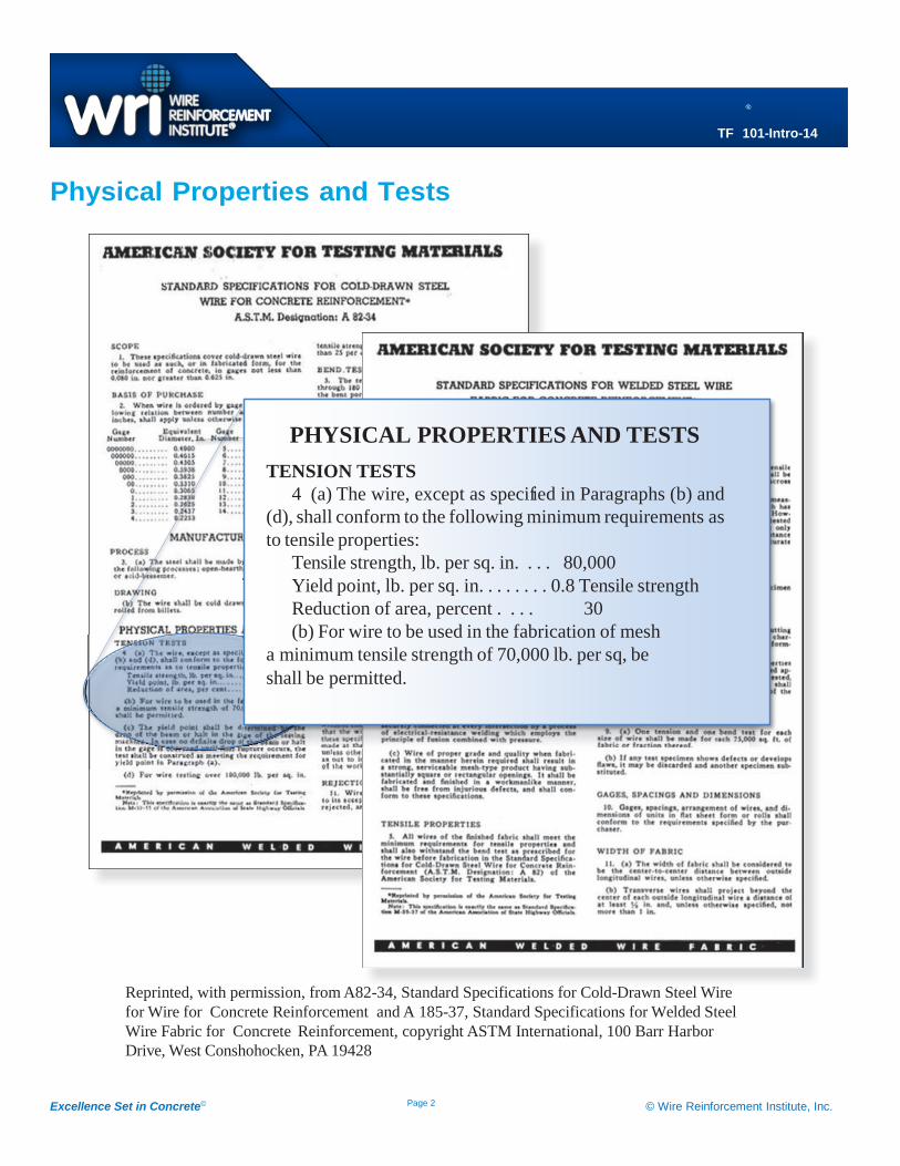
Physical Properties and Tests
PHYSICAL PROPERTIES AND TESTS
TENSION TESTS
4 (a) The wire, except as specifed in Paragraphs (b) and
(d), shall conform to the following minimum requirements as
to tensile properties:
Tensile strength, lb. per sq. in. . . . 80,000
Yield point, lb. per sq. in. . . . . . . . 0.8 Tensile strength
Reduction of area, percent . . . . 30
(b) For wire to be used in the fabrication of mesh
a minimum tensile strength of 70,000 lb. per sq, be
shall be permitted.
Reprinted, with permission, from A82-34, Standard Specifications for Cold-Drawn Steel Wire
for Wire for Concrete Reinforcement and A 185-37, Standard Specifications for Welded Steel
Wire Fabric for Concrete Reinforcement, copyright ASTM International, 100 Barr Harbor
Drive, West Conshohocken, PA 19428
Excellence Set in Concrete© Page 3 © Wire Reinforcement Institute, Inc.
TF 101-Intro-14
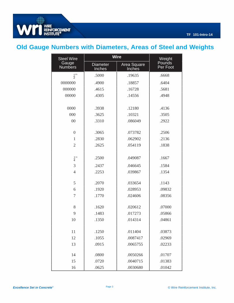
Old Gauge Numbers with Diameters, Areas of Steel and Weights
Steel Wire Gauge
Numbers
Wire Weight Pounds Per Foot
Diameter Inches
Area Square Inches
” .5000 .19635 .6668
0000000 .4900 .18857 .6404
000000 .4615 .16728 .5681
00000 .4305 .14556 .4948
0000 .3938 .12180 .4136
000 .3625 .10321 .3505
00 .3310 .086049 .2922
0 .3065 .073782 .2506
1 .2830 .062902 .2136
2 .2625 .054119 .1838
” .2500 .049087 .1667
3 .2437 .046645 .1584
4 .2253 .039867 .1354
5 .2070 .033654 .1143
6 .1920 .028953 .09832
7 .1770 .024606 .08356
8 .1620 .020612 .07000
9 .1483 .017273 .05866
10 .1350 .014314 .04861
11 .1250 .011404 .03873
12 .1055 .0087417 .02969
13 .0915 .0065755 .02233
14 .0800 .0050266 .01707
15 .0720 .0040715 .01383
16 .0625 .0030680 .01042
Excellence Set in Concrete© Page 4 © Wire Reinforcement Institute, Inc.
TF 101-Intro-14
Description of Triangle Mesh Reinforcement
TRIANGLE MESH WOVEN WIRE REINFORCEMENT
is made from cold drawn mild steel having a high breaking
strength, the longitudinal or tension members are spaced 4
inches, the diagonal cross wires either 2, 4 or 8 inches. For the
light styles of fabric the one wire, for the medium styles two
styles three wires stranded. The size
TRIANGLE MESH REINFORCEMENT is regularly
made in standard rolls but can be furnished straightened and
cut to lengths when required providing the tonnage is of
sufficient amount. As a general rule roll material can be more
easily handled and installed in the work and should be
preferred by the user.
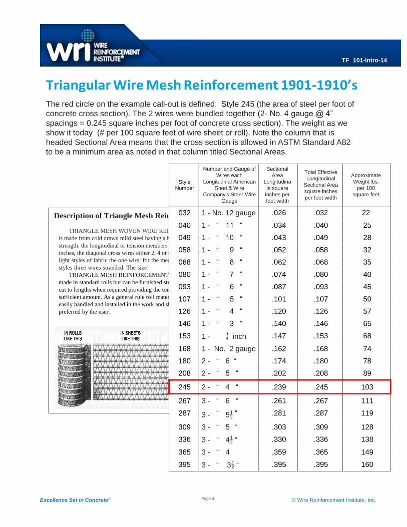
Triangular Wire Mesh Reinforcement 1901-1910’s The red circle on the example call-out is defined: Style 245 (the area of steel per foot of
concrete cross section). The 2 wires were bundled together (2- No. 4 gauge @ 4”
spacings = 0.245 square inches per foot of concrete cross section). The weight as we
show it today (# per 100 square feet of wire sheet or roll). Note the column that is
headed Sectional Area means that the cross section is allowed in ASTM Standard A82
to be a minimum area as noted in that column titled Sectional Areas.
Style Number
Number and Gauge of
Wires each
Longitudinal American
Steel & Wire
Company’s Steel Wire
Gauge
Sectional
Area
Longitudina
ls square
inches per
foot width
Total Effective
Longitudinal
Sectional Area
square inches
per foot width
Approximate
Weight lbs.
per 100
square feet
032 1 - No. 12 gauge .026 .032 22
040 1 - “ 11 “ .034 .040 25
049 1 - “ 10 “ .043 .049 28
058 1 - “ 9 “ .052 .058 32
068 1 - “ 8 “ .062 .068 35
080 1 - “ 7 “ .074 .080 40
093 1 - “ 6 “ .087 .093 45
107 1 - “ 5 “ .101 .107 50
126 1 - “ 4 “ .120 .126 57
146 1 - “ 3 “ .140 .146 65
153 1 - inch .147 .153 68
168 1 - No. 2 gauge .162 .168 74
180 2 - “ 6 “ .174 .180 78
208 2 - “ 5 “ .202 .208 89
245 2 - “ 4 “ .239 .245 103
267 3 - “ 6 “ .261 .267 111
287 3 - “ 5“ .281 .287 119
309 3 - “ 5 “ .303 .309 128
336 3 - “ 4“ .330 .336 138
365 3 - “ 4 .359 .365 149
395 3 - “ 3 “ .395 .395 160
Excellence Set in Concrete© Page 5 © Wire Reinforcement Institute, Inc.
TF 101-Intro-14
WWR from 1915-1960’s
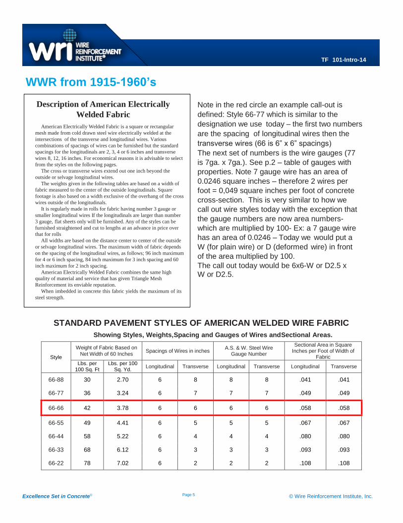
Note in the red circle an example call-out is
defined: Style 66-77 which is similar to the
designation we use today – the first two numbers
are the spacing of longitudinal wires then the
transverse wires (66 is 6” x 6” spacings)
The next set of numbers is the wire gauges (77
is 7ga. x 7ga.). See p.2 – table of gauges with
properties. Note 7 gauge wire has an area of
0.0246 square inches – therefore 2 wires per
foot = 0,049 square inches per foot of concrete
cross-section. This is very similar to how we
call out wire styles today with the exception that
the gauge numbers are now area numbers-
which are multiplied by 100- Ex: a 7 gauge wire
has an area of 0.0246 – Today we would put a
W (for plain wire) or D (deformed wire) in front
of the area multiplied by 100.
The call out today would be 6x6-W or D2.5 x W or D2.5.
STANDARD PAVEMENT STYLES OF AMERICAN WELDED WIRE FABRIC
Showing Styles, Weights, Spacing and Gauges of Wires and Sectional Areas.
Style
Weight of Fabric Based on
Net Width of 60 Inches Spacings of Wires in inches
A.S. & W. Steel Wire Gauge Number
Sectional Area in Square Inches per Foot of Width of
Fabric
Lbs. per 100 Sq. Ft
Lbs. per 100 Sq. Yd.
Longitudinal Transverse Longitudinal Transverse Longitudinal Transverse
66-88 30 2.70 6 8 8 8 .041 .041
66-77 36 3.24 6 7 7 7 .049 .049
66-66 42 3.78 6 6 6 6 .058 .058
66-55 49 4.41 6 5 5 5 .067 .067
66-44 58 5.22 6 4 4 4 .080 .080
66-33 68 6.12 6 3 3 3 .093 .093
66-22 78 7.02 6 2 2 2 .108 .108
Description of American Electrically
Welded Fabric
American Electrically Welded Fabric is a square or rectangular
mesh made from cold drawn steel wire electrically welded at the
intersections of the transverse and longitudinal wires. Various
combinations of spacings of wires can be furnished but the standard
spacings for the longitudinals are 2, 3, 4 or 6 inches and transverse
wires 8, 12, 16 inches. For economical reasons it is advisable to select
from the styles on the following pages.
The cross or transverse wires extend out one inch beyond the
outside or selvage longitudinal wires.
The weights given in the following tables are based on a width of
fabric measured to the center of the outside longitudinals. Square
footage is also based on a width exclusive of the overhang of the cross
wires outside of the longitudinals.
It is regularly made in rolls for fabric having number 3 gauge or
smaller longitudinal wires If the longitudinals are larger than number
3 gauge, flat sheets only will be furnished. Any of the styles can be
furnished straightened and cut to lengths at an advance in price over
that for rolls
All widths are based on the distance center to center of the outside
or selvage longitudinal wires. The maximum width of fabric depends
on the spacing of the longitudinal wires, as follows; 96 inch maximum
for 4 or 6 inch spacing, 84 inch maximum for 3 inch spacing and 60
inch maximum for 2 inch spacing.
American Electrically Welded Fabric combines the same high
quality of material and service that has given Triangle Mesh
Reinforcement its enviable reputation.
When imbedded in concrete this fabric yields the maximum of its
steel strength.
.
Excellence Set in Concrete© Page 6 © Wire Reinforcement Institute, Inc.
TF 101-Intro-14
A Story on the History of Wire and Welded Wire for Concrete Reinforcement
Over a hundred years ago in 1901, patent papers were fi led by Massachusetts inventor John Perry
for a machine that was able to weld together wires in sheet form. While his initial idea was to use
welded wire sheets as fences, by 1906 catalogues were advertising these sheets as reinforcement
for concrete.
In 1908, we saw the first major application of wire reinforcement in the construction of the Long
Island Parkway. While it was only a lightweight mesh reinforcement weighing only 0.2 lbs. per sq/ft,
it represented a step forward. From 1908 until the start of World War I, many eastern states
specified wire reinforcement in pavement, eventually increasing to weights of about 0.65 lbs/sq ft.
It is not clear when welded wire was first used with Portland Cement for concrete pavement.
Between 1910 and 1915, stretches of pavement in DeKalb, Illinois, California and Forest Park,
Maryland were poured using WWR. However, the DuPont Road in Delaware, also shares honors.
The road was the forerunner of all superhighways and was built with a
variety of reinforcing materials, including welded wire reinforcement.
While it was built using specs that we know today are not conducive to
long life, it was another major development in the viability of WWR.
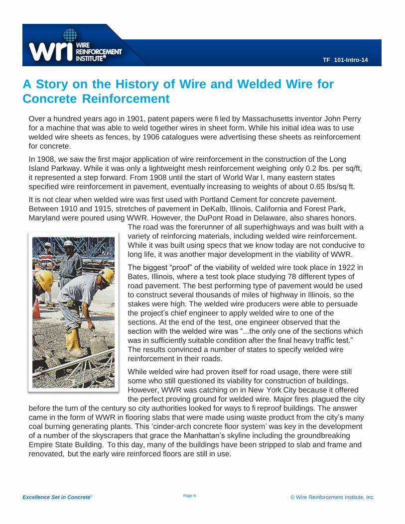
The biggest “proof” of the viability of welded wire took place in 1922 in
Bates, Illinois, where a test took place studying 78 different types of
road pavement. The best performing type of pavement would be used
to construct several thousands of miles of highway in Illinois, so the
stakes were high. The welded wire producers were able to persuade
the project’s chief engineer to apply welded wire to one of the
sections. At the end of the test, one engineer observed that the
section with the welded wire was “...the only one of the sections which
was in sufficiently suitable condition after the final heavy traffic test.”
The results convinced a number of states to specify welded wire
reinforcement in their roads.
While welded wire had proven itself for road usage, there were still
some who still questioned its viability for construction of buildings.
However, WWR was catching on in New York City because it offered
the perfect proving ground for welded wire. Major fires plagued the city
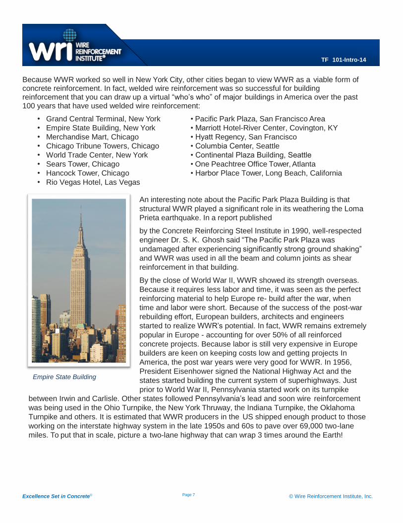
before the turn of the century so city authorities looked for ways to fi reproof buildings. The answer
came in the form of WWR in flooring slabs that were made using waste product from the city’s many
coal burning generating plants. This ‘cinder-arch concrete floor system’ was key in the development
of a number of the skyscrapers that grace the Manhattan’s skyline including the groundbreaking
Empire State Building. To this day, many of the buildings have been stripped to slab and frame and
renovated, but the early wire reinforced floors are still in use.
Excellence Set in Concrete© Page 7 © Wire Reinforcement Institute, Inc.
TF 101-Intro-14
Because WWR worked so well in New York City, other cities began to view WWR as a viable form of concrete reinforcement. In fact, welded wire reinforcement was so successful for building reinforcement that you can draw up a virtual “who’s who” of major buildings in America over the past 100 years that have used welded wire reinforcement:
• Grand Central Terminal, New York • Pacific Park Plaza, San Francisco Area
• Empire State Building, New York • Marriott Hotel-River Center, Covington, KY
• Merchandise Mart, Chicago • Hyatt Regency, San Francisco
• Chicago Tribune Towers, Chicago • Columbia Center, Seattle
• World Trade Center, New York • Continental Plaza Building, Seattle
• Sears Tower, Chicago • One Peachtree Office Tower, Atlanta
• Hancock Tower, Chicago • Harbor Place Tower, Long Beach, California
• Rio Vegas Hotel, Las Vegas An interesting note about the Pacific Park Plaza Building is that
structural WWR played a significant role in its weathering the Loma
Prieta earthquake. In a report published
by the Concrete Reinforcing Steel Institute in 1990, well-respected
engineer Dr. S. K. Ghosh said “The Pacific Park Plaza was
undamaged after experiencing significantly strong ground shaking”
and WWR was used in all the beam and column joints as shear
reinforcement in that building.
By the close of World War II, WWR showed its strength overseas.
Because it requires less labor and time, it was seen as the perfect
reinforcing material to help Europe re- build after the war, when
time and labor were short. Because of the success of the post-war
rebuilding effort, European builders, architects and engineers
started to realize WWR’s potential. In fact, WWR remains extremely
popular in Europe - accounting for over 50% of all reinforced
concrete projects. Because labor is still very expensive in Europe
builders are keen on keeping costs low and getting projects In
America, the post war years were very good for WWR. In 1956,
President Eisenhower signed the National Highway Act and the
states started building the current system of superhighways. Just
prior to World War II, Pennsylvania started work on its turnpike
between Irwin and Carlisle. Other states followed Pennsylvania’s lead and soon wire reinforcement
was being used in the Ohio Turnpike, the New York Thruway, the Indiana Turnpike, the Oklahoma
Turnpike and others. It is estimated that WWR producers in the US shipped enough product to those
working on the interstate highway system in the late 1950s and 60s to pave over 69,000 two-lane
miles. To put that in scale, picture a two-lane highway that can wrap 3 times around the Earth!
Empire State Building
Excellence Set in Concrete© Page 8 © Wire Reinforcement Institute, Inc.
TF 101-Intro-14
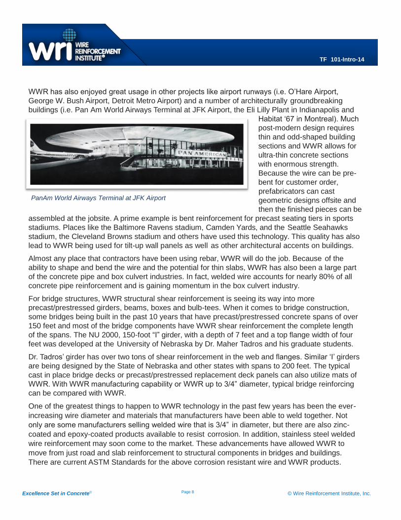
WWR has also enjoyed great usage in other projects like airport runways (i.e. O’Hare Airport,
George W. Bush Airport, Detroit Metro Airport) and a number of architecturally groundbreaking
buildings (i.e. Pan Am World Airways Terminal at JFK Airport, the Eli Lilly Plant in Indianapolis and
Habitat ‘67 in Montreal). Much
post-modern design requires
thin and odd-shaped building
sections and WWR allows for
ultra-thin concrete sections
with enormous strength.
Because the wire can be pre-
bent for customer order,
prefabricators can cast
geometric designs offsite and
then the finished pieces can be
assembled at the jobsite. A prime example is bent reinforcement for precast seating tiers in sports
stadiums. Places like the Baltimore Ravens stadium, Camden Yards, and the Seattle Seahawks
stadium, the Cleveland Browns stadium and others have used this technology. This quality has also
lead to WWR being used for tilt-up wall panels as well as other architectural accents on buildings.
Almost any place that contractors have been using rebar, WWR will do the job. Because of the
ability to shape and bend the wire and the potential for thin slabs, WWR has also been a large part
of the concrete pipe and box culvert industries. In fact, welded wire accounts for nearly 80% of all
concrete pipe reinforcement and is gaining momentum in the box culvert industry.
For bridge structures, WWR structural shear reinforcement is seeing its way into more
precast/prestressed girders, beams, boxes and bulb-tees. When it comes to bridge construction,
some bridges being built in the past 10 years that have precast/prestressed concrete spans of over
150 feet and most of the bridge components have WWR shear reinforcement the complete length
of the spans. The NU 2000, 150-foot “I” girder, with a depth of 7 feet and a top flange width of four
feet was developed at the University of Nebraska by Dr. Maher Tadros and his graduate students.
Dr. Tadros’ girder has over two tons of shear reinforcement in the web and flanges. Similar ‘I’ girders
are being designed by the State of Nebraska and other states with spans to 200 feet. The typical
cast in place bridge decks or precast/prestressed replacement deck panels can also utilize mats of
WWR. With WWR manufacturing capability or WWR up to 3/4” diameter, typical bridge reinforcing
can be compared with WWR.
One of the greatest things to happen to WWR technology in the past few years has been the ever-
increasing wire diameter and materials that manufacturers have been able to weld together. Not
only are some manufacturers selling welded wire that is 3/4” in diameter, but there are also zinc-
coated and epoxy-coated products available to resist corrosion. In addition, stainless steel welded
wire reinforcement may soon come to the market. These advancements have allowed WWR to
move from just road and slab reinforcement to structural components in bridges and buildings.
There are current ASTM Standards for the above corrosion resistant wire and WWR products.
PanAm World Airways Terminal at JFK Airport
Excellence Set in Concrete© Page 9 © Wire Reinforcement Institute, Inc.
TF 101-Intro-14
This Modern Era
WWR is what the industry today refers to for all styles of Welded Wire Reinforcement. Every change
involves a period of transition. For instance, in much of WRI’s literature, WWR is often referred to as
fabric or mesh or WWF, which imply light reinforcing materials. However, this industry is continuing to
grow into what we call the structural WWR market. Future ASTM standards, e.g., Volume 01.04--Steel
Reinforcement--will reflect this change of wording, from fabric and mesh to reinforcement.
With further changes to heavier wire and the structural WWR market tonnage increasing each year,
structural reinforcement describes the product much more accurately. To be more specific, anytime an
engineer uses a moment capacity similar to the one published as Mn in ACI 318, Chapters 9, 14, 15
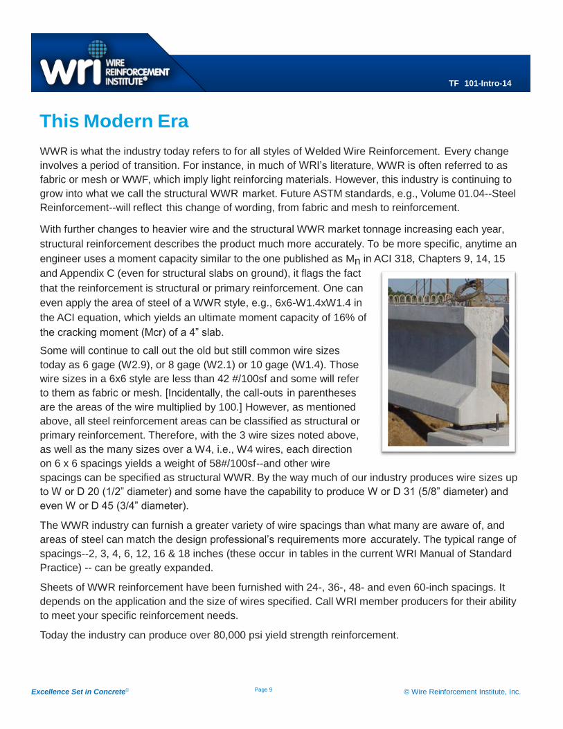
and Appendix C (even for structural slabs on ground), it flags the fact
that the reinforcement is structural or primary reinforcement. One can
even apply the area of steel of a WWR style, e.g., 6x6-W1.4xW1.4 in
the ACI equation, which yields an ultimate moment capacity of 16% of
the cracking moment (Mcr) of a 4” slab.
Some will continue to call out the old but still common wire sizes
today as 6 gage (W2.9), or 8 gage (W2.1) or 10 gage (W1.4). Those
wire sizes in a 6x6 style are less than 42 #/100sf and some will refer
to them as fabric or mesh. [Incidentally, the call-outs in parentheses
are the areas of the wire multiplied by 100.] However, as mentioned
above, all steel reinforcement areas can be classified as structural or
primary reinforcement. Therefore, with the 3 wire sizes noted above,
as well as the many sizes over a W4, i.e., W4 wires, each direction
on 6 x 6 spacings yields a weight of 58#/100sf--and other wire
spacings can be specified as structural WWR. By the way much of our industry produces wire sizes up
to W or D 20 (1/2” diameter) and some have the capability to produce W or D 31 (5/8” diameter) and
even W or D 45 (3/4” diameter).
The WWR industry can furnish a greater variety of wire spacings than what many are aware of, and
areas of steel can match the design professional’s requirements more accurately. The typical range of
spacings--2, 3, 4, 6, 12, 16 & 18 inches (these occur in tables in the current WRI Manual of Standard
Practice) -- can be greatly expanded.
Sheets of WWR reinforcement have been furnished with 24-, 36-, 48- and even 60-inch spacings. It
depends on the application and the size of wires specified. Call WRI member producers for their ability
to meet your specific reinforcement needs.
Today the industry can produce over 80,000 psi yield strength reinforcement.


![INDEX [] · Links & Rings INDEX PAGE Senhouse Slips & Webbing Slings PAGE Wire Rope Sheaves PAGE Miscellaneous PAGE TRIANGULAR LINKS to BS2837 Table 1 1970](https://img.pdfslide.us/doc/110x75/5acf16877f8b9ae2138c1738/index-rings-index-page-senhouse-slips-webbing-slings-page-wire-rope-sheaves.jpg)