Embed Size (px)
Citation preview
HIGHWAY CONSTRUCTION DETAILS (700 SERIES)
VOLUME 1:
GENERAL DETAILS
TRANSPORT & ECONOMY
COLLATED: MAY 2018
PRODUCED BY DESIGN SERVICES COMMUNITIES SHIRE HALL WARWICK CV34 4SP

HIGHWAY CONSTRUCTION DETAILS: 700 SERIES VOLUME 1: GENERAL DETAILS CONTENTS NOTES FOR GUIDANCE
Description Issued
NOTES FOR GUIDANCE MAY 2018
NOTES FOR GUIDANCE ANNEX 1 MAY 2018
HIGHWAY CROSS SECTIONS
Number Description Issued
A 701.1 CUTTING & EMBANKMENTS: SINGLE CARRIAGEWAYS MAY 2018
A 701.2 CUTTING & EMBANKMENTS: DUAL CARRIAGEWAYS MAY 2018
A 701.3 SUB-BASE & THE EARTHWORKS OUTLINE MAY 2018
EDGE OF PAVEMENT DETAILS
Number Description Issued
B 701.1 CARRIAGEWAYS WITH CONCRETE KERBING MAY 2018
B 701.2 CARRIAGEWAYS WITHOUT CONCRETE KERBING MAY 2018
B 701.3 PAVING ON ROUNDABOUT ISLANDS MAY 2018
B 702.1 KERBS, EDGING & CHANNELS MAY 2018
B 704.1 FOOTWAY & CYCLEWAY CONSTRUCTION (BITUMINOUS) MAY 2018
B 704.2 ACCESS CONSTRUCTION MAY 2018
B 704.3 BLOCK PAVING: LAYING PATTERNS AND EDGE RESTRAINTS MAY 2018
B 704.4 BUS BOARDING POINT (QUALITY BUS CORRIDOR) WITH KASSEL KERBS
MAY 2018
B 704.5 FOOTWAY & CYCLEWAY CONSTRUCTION (BLOCK & FLAG PAVING)
MAY 2018
B 704.6 FOOTWAY & CYCLEWAY CONSTRUCTION (NO DIG OPTION) MAY 2018
B 705.1 STRIP WIDENING & LONGITUDINAL JOINTING DETAILS MAY 2018
B 705.2 OVERLAY & TRANSVERSE JOINTING DETAILS MAY 2018
B 706.1 BUILD OUTS FOR ROAD NARROWINGS & CHICANES MAY 2018
B 707.1 MAINTENANCE BAY (WITH PERMEABLE CONCRETE PAVERS) MAY 2018
DRAINAGE
Number Description Issued
F 701.1 SURFACE WATER DRAINS: BEDDING & TRENCH DETAILS APRIL 2016
F 702.1 FILTER DRAINS: BEDDING & TRENCH DETAILS SHEET 1 APRIL 2016
F 702.2 FILTER DRAINS: BEDDING & TRENCH DETAILS SHEET 2 MAY 2018
F 703.1 PRECAST CONCRETE CATCHPITS: TYPES 71 & 72 MAY 2018
F 703.2 BRICK CATCHPIT: TYPE 73 MAY 2018
F 704.1 GULLIES: TYPES 1, 2A & 2B MAY 2018
F 704.2 GULLY CONNECTIONS & RODDING EYES MAY 2018
F 705.1 HEADWALLS: TYPES 1, 2 & 3 WITH DITCH LINING DETAIL APRIL 2016
F 706.1 CONNECTION OF PERMANENTLY SEVERED LAND DRAINS MAY 2018
F 707.1 CONCRETE PIPE SADDLES MAY 2018
FENCES, STILES AND GATES
Number Description Issued
H 701.1 BOUNDARY HEDGE APRIL 2016
H 702.1 FENCING: TIMBER POST & RAIL MAY 2018
H 703.1 TIMBER FIELD GATES: TYPES 1, 2 & 3 MAY 2018
UNDERGROUND CABLE DUCTS
Number Description Issued
I 701.1 NEW SERVICE DUCTS & PROTECTION OF EXISTING SERVICES MAY 2018
I 702.1 ACCESS CHAMBERS FOR SERVICE DUCTS MAY 2018
MISCELLANEOUS
Number Description Issued
K 701.1 TRENCH REINSTATEMENT IN CARRIAGEWAYS & PAVED AREAS APRIL 2016
K 702.1 PEDESTRIAN GUARDRAILS MAY 2018
K 703.1 TYPE 1 REFUGES & PEDESTRIAN REFUGES: WITH MAINS POWERED BOLLARDS & SIGNS
APRIL 2016
K 703.2 TYPE 2 REFUGES & PEDESTRIAN REFUGES: WITH FLEXIBLE SOLAR BOLLARDS
MAY 2018
K 703.4 TYPE 3 REFUGES & PEDESTRIAN REFUGES: WITH FLEXIBLE BOLLARDS & MAINS POWERED SIGNS
APRIL 2016
K 703.6 BOLLARDS: SOLAR AND UNLIT MAY 2018
K 703.7 BOLLARDS: MAINS POWERED APRIL 2016
K 704.1 TRAFFIC SIGNS: FABRICATION & MOUNTING DETAILS MAY 2018
K 705.1 SIGN BOARD DETAILS: TYPES A, B, C & D APRIL 2016
K 705.2 SIGN BOARD DETAILS: TYPE E MAJOR SCHEME INFORMATION BOARD
APRIL 2016
K 706.1 TRAFFIC SIGNALS: CONTROLLER WITH CONTROLLER BASE APRIL 2016
K 706.2 TRAFFIC SIGNALS: STANDARD DETAILS MAY 2018
K 706.3 TRAFFIC SIGNALS: ZEBRA CROSSINGS MAY 2018

HIGHWAY CONSTRUCTION DETAILS: 700 SERIES VOLUME 1: GENERAL DETAILS NOTES FOR GUIDANCE INTRODUCTION
GENERAL
1. These notes apply to all Design Offices preparing schemes for Warwickshire County Council. They refer to the Highway Construction Details: 700 Series (HCD 700s) listed on the preceding contents page.
2. Designers shall use the HCD 700s instead of any similarly titled drawings or details issued by Highways England (HE). HE’s Highway Construction Details (HCDs) are contained in the Manual of Contract Documents for Highway Works: Volume 3.
3. HE’s HCDs have generally been prepared for use on Motorways and Trunk Roads. Experience has shown that for County Roads there is a need to:
3.1 modify some of the HCDs to suit local conditions; and 3.2 produce details where none exist.
The HCD 700s and associated Notes for Guidance reflect these needs.
4. In some cases, the Notes for Guidance listed below refer to numbered appendices such as Appendix 5/1. These numbered appendices relate to those included in the modified and extended Specification, which forms part of the County Council’s standard contract document for highway construction works.
5. Companies tendering for County Council construction contracts will be issued with either the complete set of HCD 700s, or a set of those HCD 700 details that are relevant to the particular contract. All relevant HCD 700s will be listed in Appendix 0/4 of the modified and extended Specification.
6. From time to time, the HCD 700s and associated Notes for Guidance may be updated. At such times, the issue date and issue status will be amended accordingly.
7. Complete volumes of the HCD 700s may be sent to contractors or developers in pdf form. County Council staff sending out such copies must make recipients aware that the HCD 700s may be updated and reissued periodically. Recipients must also be made aware that it is their responsibility to ensure that they are working to the most up-to-date issue. This principle does not apply where copies are despatched to tenderers as part of a set of contract documents.
8. Designers should note that the HCD 700s represent the preferred requirements of the County Council. Nevertheless, in certain circumstances, variations may be necessary. In such circumstances, the variations shall be made clear on either the scheme specific construction drawings or the numbered appendices of the modified and extended Specification. Neither the HCD 700s nor the HCDs shall be altered in any way.
9. Designers wishing to apply any variation to the HCD 700s on County Council
construction projects must first agree the variation with WCC’s Design Services. Designers proposing to apply the HCD 700s on construction projects where the County Council is not the client must first agree to do so with the client concerned.
10. Any comments, queries or suggestions for improvement relating to the HCD 700s should be addressed to:
The Group Manager Design Services Communities Shire Hall Post Room Northgate Street Warwick CV34 4SP
HIGHWAY CROSS SECTIONS
A 701.1 CUTTING & EMBANKMENT: SINGLE CARRIAGEWAY
1. Refer to B 701.1 and B 701.2 for edge details.
2. Lighting columns are usually positioned 2.0m back from the kerb face. This may be varied but if so, the new position must be stated in the contract documents. County Highways’ Street Lighting section must approve in advance any variation to the usual position of lighting columns.
A 701.2 CUTTING & EMBANKMENT: DUAL CARRIAGEWAY
1. Refer to the notes for A 701.1.
EDGE OF PAVEMENT DETAILS
B 701.1 CARRIAGEWAYS WITH CONCRETE KERBING
1. Refer to F 702.1, F 702.2 and Appendix 5/1 for filter drain details.
B 701.2 CARRIAGEWAYS WITHOUT CONCRETE KERBING
1. Refer to the notes for B 701.1.
B 701.3 PAVING ON ROUNDABOUT ISLANDS
1. Kerb types shall be stated in the contract documents, either in a schedule or on the scheme specific drawings.

EDGE OF PAVEMENT DETAILS (cont’d)
B 702.1 KERBS, EDGING & CHANNELS
1. Refer to the notes for B 701.3.
B 704.2 ACCESS CONSTRUCTION
1. Type 1 Access Construction is intended for residential use. Type 2 Access Construction is intended for industrial use.
B 704.3 BLOCK PAVING
1. Block paving details shall be included in Appendix 11/1.
DRAINAGE
F 701.1 SURFACE WATER DRAINS: BEDDING & TRENCH DETAILS
1. The details of permitted alternatives are shown in Notes for Guidance: Annex 1, Table 1. Generally, three types of pipe material (vitrified clay, concrete and certain approved polymer materials) are permitted. Only pipes manufactured from the polymer materials specified in S.H.W. Table 5/1 will be permitted, unless they hold a current British Board of Agrément Roads and Bridges Certificate (or equivalent) stating that they are a suitable alternative for the ‘usage’ specified in S.H.W. Table 5/1.
2. Table 1 states the minimum cover requirement for each pipe group. Design engineers should examine the particular circumstances for each pipe length to determine whether or not the pipe group recommended by the table is appropriate. For example, if a pipe has a depth of cover less than 0.9m, but is located in soft ground so far from the carriageway that it is very unlikely to be trafficked; a concrete surround to the pipe may not be necessary.
3. It should be noted that bedding (including laying and any pipe surround) comprises all operations up to an including 0.3m above the pipe soffit. Backfilling comprises all operations from this point up to ground level, formation level or sub-formation level, whichever applies.
4. If sulphate-resisting cement needs to be used in any concrete pipe surround, it must be specified in Appendix 26/1.
5. It should be noted that all pipes are designed for the final serviceable condition. Pipes are not designed to take into account loadings imposed by construction traffic.
6. If surface water drains are to be adopted by the Sewer Authority, the specifications of that authority take precedence over the specifications provided in these details.
7. Bedding and trench details for the drains included in M.C.D. Vol. 3 have now been incorporated into this system.
F 702
FILTER DRAINS: BEDDING & TRENCH DETAILS
1. The details of permitted alternatives are shown in Notes for Guidance: Annex 1, Table 2. Refer to the notes for F 701.1.
2. Group F7 drains alone shall only be used to drain formation/sub-formation where there is either no embankment, or where there is an embankment, but its height is negligible. Group F7 drains must not be used for the purpose of controlling the water table level. Where there is an embankment of a significant height, Group F7 drains must be accompanied by a suitable filter drain at the foot of the embankment.
F 707.1 CONCRETE PIPE SADDLES
1. If surface water drains are to be adopted by the Sewer Authority, the Authority’s specification for pipe connections takes precedence over the specification provided in this detail.
FENCES, STILES AND GATES
H 701.1 BOUNDARY HEDGE
1. Plant species in rural Warwickshire shall be chosen from those listed for hedges in that part of the county. The list of plant species can be found in the appropriate volume of ‘Warwickshire Landscapes Guidelines’.
H 703.1 TIMBER FIELD GATES: TYPES 1, 2 & 3
1. Gates shall comply with the requirements of S.H.W. Series 300. Additional requirements shall be specified in Appendix 1/15 and/or Appendix 3/1.
UNDERGROUND CABLE DUCTS
I 701.1 NEW SERVICE DUCTS & PROTECTION OF EXISTING SERVICES
1. The details of permitted duct alternatives are shown in Notes for Guidance: Annex 1, Table 3. Only two types of duct pipe material (vitrified clay and PVC-U) are permitted, and these shall comply with the requirements of S.H.W. Table 5/2.
MISCELLANEOUS
K 701.1 TRENCH REINSTATEMENT IN CARRIAGEWAYS & PAVED AREAS
1. Permitted materials shall be stated in Appendix 7/1. Any alterations to the depths of construction shown shall be stated in Appendix 7/2.
K 702.1 PEDESTRIAN GUARDRAILS
1. Any special requirements shall be stated in Appendix 4/2.
2. High visibility pedestrian guardrail panels shall be provided at pedestrian crossing points.

MISCELLANEOUS (cont’d)
K 703 REFUGES & PEDESTRIAN REFUGES
1. Lighting details, including electrical work shall be stated in Appendix 14/2 and Appendix 14/4. There are two alternatives to the Standard Illuminated Refuge & Pedestrian Refuge (K 703.1), which are shown on details K 703.2 and K703.4. Wherever a refuge is required, designers should seek advice from the Communities’ Traffic Group on which refuge detail to specify.

HIGHWAY CONSTRUCTION DETAILS (700 SERIES) VOLUME 1: GENERAL DETAILS NOTES FOR GUIDANCE ANNEX 1 TABLE 1: SPECIFICATION FOR SURFACE WATER DRAINS
PIPE GROUP DEPTH OF COVER PIPE MATERIAL
VITRIFIED CLAY CONCRETE APPROVED POLYMER MATERIAL
PIPE STANDARD BEDDING & TRENCH DETAIL
PIPE STANDARD BEDDING & TRENCH DETAIL
PIPE STANDARD BEDDING & TRENCH DETAIL
S2 0.6m - 0.9m refer to note 1. Z L Z refer to note 2. Y
S3 0.9m – 5.0m refer to note 1. S M S refer to note 2. S
S7 (below c/way) 0.6m - 0.9m refer to note 1. Z1 M Z1 refer to note 2. Y1
S8 (below c/way) 0.9m – 5.0m refer to note 1. S1 M S1 refer to note 2. S1
TABLE 2: SPECIFICATION FOR FILTER DRAINS
PIPE GROUP DEPTH OF COVER PIPE MATERIAL
VITRIFIED CLAY CONCRETE APPROVED POLYMER MATERIAL
PIPE STANDARD BEDDING & TRENCH DETAIL
PIPE STANDARD BEDDING & TRENCH DETAIL
PIPE STANDARD BEDDING & TRENCH DETAIL
F2 0.9m – 2.0m ES G L G refer to note 2. J
F3 0.9m – 2.0m ES L L L refer to note 2. L
F4 0.9m – 2.0m ES H1 L H1 refer to note 2. I
F5 0.9m – 2.0m ES M L M refer to note 2. M
F6 0.9m – 2.0m ES K L K refer to note 2. K
F7 refer to note 3. not applicable not applicable not applicable not applicable refer to note 2. not applicable
F8 refer to note 3. ES Q L Q refer to note 2. Q
F9A 0.6m not applicable not applicable not applicable not applicable refer to note 2. not applicable
F9B 0.6m not applicable not applicable not applicable not applicable refer to note 2. not applicable
NOTES
1. As per HA 40/01: Where the nominal diameter (DN) = 150mm, the pipe crushing strength shall be 22KN/m. Where DN ≥ 225mm, the pipe standard shall be ≥ Class 160.
2. Approved polymer materials shall be those listed in S.H.W. Table 5/1. Alternative polymer materials may be permitted, provided that they hold a current British Board of Agrément Roads and Bridges Certificate (or equivalent) stating that they are a suitable alternative for the ‘usage’ specified in S.H.W. Table 5/1.
3. The depth of cover on Group F7 drains shall be 0.3m plus the thickness of lower sub-base layer if specified. The depth of cover on Group F8 drains shall be 0.6m, or the external pipe diameter + 0.05m + the thickness of lower sub-base layer (if specified), whichever is the greater.
4. Where PVC-U (ultra-rib twin wall) pipes are to be used, the short-term ring stiffness shall be ≥ 8.0KN/m². The fifty-year stiffness shall be ≥ 3.0KN/m².

HIGHWAY CONSTRUCTION DETAILS (700 SERIES) VOLUME 1: GENERAL DETAILS NOTES FOR GUIDANCE ANNEX 1 TABLE 3: SPECIFICATION FOR NEW SERVICE DUCTS
DUCT GROUP DEPTH OF COVER DUCT PIPE MATERIAL
VITRIFIED CLAY PVC-U
DUCT PIPE STANDARD BEDDING & TRENCH DETAIL DUCT PIPE STANDARD BEDDING & TRENCH DETAIL
D1 0.90m min. (below c/way) ES D1 refer to note 1. D1
D2 0.75m min. (below verge) ES D2 refer to note 1. D2
NOTES
1. The duct pipe standard for PVC-U duct pipes shall be in accordance with S.H.W. Table 5/2.

DETAIL WITHOUT FILTER DRAIN
limit of topsoil strip
300mm W75 material to clause 890AR
(where lower sub-base specified)
sub-base
topsoil
F
TYPICAL SECTION - EMBANKMENT
(where lower sub-base specified)
F
150mm Type 1 upper sub-base
material (where no lower sub-base
layer specified) otherwise
F
2000 min
varies (see note 8)
b
width as specified
b
varies (see note 8)
2000 min
1000 1000
625
625
as scheduled
filter drain (where specified)
limit of topsoil strip
gully connection
(refer to F 704.2)
filter drain Type P
(Group F7)
gully
varies
lighting
column
5%
F
F
5%
topsoil
limit of topsoil strip
topsoil
filter drain (where specified)
TYPICAL SECTION - CUTTING
2000 min
varies (see note 8)
b
width as specified
b
varies (see note 8)
2000 min
as scheduled
1250
1250
as specified
625
highway boundary
(typically to H 701.1)
topsoil
lighting
column
5%
gully connection
(refer to F 704.2)
limit of topsoil strip
filter drain (where specified)
gully
F
5% varies
sub-base
F
5%
filter drain (where specified)
limit of topsoil strip
cut off drain (where specified)
base
5%
topsoil
base
sub-base
base
edge line
a
(see note 9)
a
(see note 9)
edge line
edge line
edge line
a
(see note 9)
a
(see note 9)
highway boundary
(typically to H 701.1)
highway boundary
(typically to H 701.1)
highway boundary
(typically to H 701.1)
HIGHWAY
CONSTRUCTION
DETAILS (HCD-700)
DRAWING NUMBER ISSUE DATE
DRAWN CHECKED
ALL DIMENSIONS IN MILLIMETRES UNLESS OTHERWISE STATED. DO NOT SCALE FROM THIS DRAWING.
SHEET SIZE
ISSUEPREVIOUS ISSUES
SECTION TITLE APPROVED
HIGHWAY CROSS SECTIONS
CUTTING & EMBANKMENTS:
SINGLE CARRIAGEWAYS
A 701.1
5
MAY 2018A3
RJP DM AC
1 FEB 2005
2 MAY 2010
3 APR 2016
4 FEB 2017
This drawing was reproduced from a digital source and may not be at true scale. It is the recipient's responsibility to confirm its accuracy.
0mm 50mm 100mm 150mm 200mm
1. Any scheme specific cross section layouts shall take precedence over this detail.
2. On balanced carriageways, the edge detail shall be the same on both sides and
match the detail for the low side of carriageway. Refer to B 701.1 for edge
details.
3. Depth of topsoil shall be 150mm unless stated otherwise.
4. Verges may be widened to 4.5m to accommodate footways. Refer to B 704.1
for footway details.
5. F = Fill material on sub-base materials and base.
6. The position of lighting columns may vary where footways are required.
7. Refer to F 702.1 and F 702.2 for filter drain details.
8. Cutting and embankment slopes shall be 1:2 unless otherwise specified on
scheme specific drawings. For embankments with heights in excess of 3m, slope
stability calculations are normally required.
9. The 1000mm hardstrip dimension shall be measured from the edge of
carriageway (typically the kerb face), to the running lane side of the edge line.
10. For sub-base details and the position of the Earthworks Outline, refer to A 701.3.
11. Vehicle Restraint System may be required, but is not shown for simplicity.
NOTES
MINIMUM WIDTH REQUIREMENTS
Posted speed limit
Width of hardstrip
(a)
Verge width
(b)
≤ 40mph Not Required
2500mm
≥ 50mph
1000mm 2500mm

TYPICAL SECTION - EMBANKMENT
2000 min
varies (see note 5)
b
width as specified
c
width as specified
b
varies (see note 5)
2000 min
1000 2000
(see note 7)
a a
(see note 7)
a a 2000
1250
(see note 7)
1000
filter drain (where specified)
limit of topsoil strip
topsoil
lighting
column
gully
base
edge line
5%
varies5%
varies
5%
gully
5%
filter drain (where specified)
limit of topsoil strip
topsoil
lighting
column
F
F
F
F
TYPICAL SECTION - CUTTING
2000 min
varies (see note 5)
b
width as specified
c
width as specified
b
varies (see note 5)
2000 min
as specified
2000 a a
1250
(see note 7)
(see note 7)
a a
(see note 7)
1250
2000
as specified
cut off drain (where specified)
topsoil
limit of topsoil strip
filter drain (where specified)
lighting
column
F
base
sub-base
5%
varies
edge line
gully
filter drain (where specified)
FF
varies
5%5%
gully
F
5%
5%
cut off drain (where specified)
topsoil
lighting
column
limit of topsoil strip
edge line
edge line
filter drain (where specified)
filter drain (where specified)
filter drain (where specified)
(see note 6) (see note 6)
(see note 6) (see note 6)
(see note 6) (see note 6)
(see note 6) (see note 6)
5%
gully connection
(refer to F 704.2)
gully connection
(refer to F 704.2)
gully connection
(refer to F 704.2)
gully connection
(refer to F 704.2)
sub-base
highway boundary
(typically to H 701.1)
highway boundary
(typically to H 701.1)
highway boundary
(typically to H 701.1)
highway boundary
(typically to H 701.1)
VRS
VRS
VRS
VRS
VRS
VRS
HIGHWAY
CONSTRUCTION
DETAILS (HCD-700)
DRAWING NUMBER ISSUE DATE
DRAWN CHECKED
ALL DIMENSIONS IN MILLIMETRES UNLESS OTHERWISE STATED. DO NOT SCALE FROM THIS DRAWING.
SHEET SIZE
ISSUEPREVIOUS ISSUES
SECTION TITLE APPROVED
HIGHWAY CROSS SECTIONS
CUTTING & EMBANKMENTS:
DUAL CARRIAGEWAYS
A 701.2
5
MAY 2018A3
RJP DM AC
1 FEB 2005
2 MAY 2010
3 APR 2016
4 FEB 2017
This drawing was reproduced from a digital source and may not be at true scale. It is the recipient's responsibility to confirm its accuracy.
0mm 50mm 100mm 150mm 200mm
1. On balanced carriageways, the edge detail shall be the same on both
sides and match the detail for the low side of carriageway. Refer to
B 701.1 for edge details.
2. Depth of topsoil shall be 150mm unless stated otherwise.
3. F = Fill material on sub-base materials and base.
4. Refer to F 702.1 and F 702.2 for filter drain details.
5. Cutting and embankment slopes shall be 1:2 unless otherwise specified
on scheme specific drawings. For embankments with heights in excess
of 3m, slope stability calculations are normally required.
NOTES
6. The 1000mm hardstrip dimension shall be measured
from the edge of carriageway (typically the kerb
face), to the running lane side of the edge line.
7. Set-back to comply with current road restraint system
standards.
8. For sub-base details and the position of the
Earthworks Outline, refer to A 701.3.
9. At ≤ 60mph the inclusion of a hardstrip is to be
agreed with the Overseeing Organisation.
MINIMUM WIDTH REQUIREMENTS
Posted speed limit
With hardstrip Without hardstrip
Width of hardstrip
(a)
Verge width
(b)
Width of central
reserve
(c)
Verge width
(b)
Width of central
reserve
(c)
≤ 60mph
1000mm
(see note 9)
2500mm
(see note 9)
1800mm
(see note 9)
3500mm 1800mm
70mph
1000mm 2500mm 2500mm
Not appropriate

EARTHWORKS OUTLINE EXTENTS
topsoil
base
sub-base
limit of topsoil strip
SUB-BASE ARRANGEMENT
TYPE A
surface course
binder course
base
upper sub-base
lower sub-base
Earthworks Outline Earthworks Outline
SUB-BASE ARRANGEMENT
TYPE B
surface course
binder course
base
upper sub-base
lower sub-base
Earthworks Outline Earthworks Outline
SUB-BASE ARRANGEMENT
TYPE C
surface course
binder course
base
upper sub-base
Earthworks Outline Earthworks Outline
600
350
HIGHWAY
CONSTRUCTION
DETAILS (HCD-700)
DRAWING NUMBER ISSUE DATE
DRAWN CHECKED
ALL DIMENSIONS IN MILLIMETRES UNLESS OTHERWISE STATED. DO NOT SCALE FROM THIS DRAWING.
SHEET SIZE
ISSUEPREVIOUS ISSUES
SECTION TITLE APPROVED
HIGHWAY CROSS SECTIONS
SUB-BASE &
THE EARTHWORKS OUTLINE
A 701.3
2
MAY 2018A3
RJP NH AC
1 FEB 2017
This drawing was reproduced from a digital source and may not be at true scale. It is the recipient's responsibility to confirm its accuracy.
0mm 50mm 100mm 150mm 200mm
1. Sub-base depths are for general guidance only. Always refer to scheme specific information.
2. Upper sub-base is a Type 1 unbound mixture to S.H.W. Clause 803, Type 2 unbound mixture (if it
contains at least 80% bituminous planings) to S.H.W. Clause 804 or Type 3 (open graded) unbound
mixture to S.H.W. Clause 805.
3. Lower sub-base is W150 to clause 890AR. Use of W75 to clause 890AR is permitted for lower
sub-base construction widths of less than 1.5m.
4. For areas with CBR values of less than 1.5% seek specialist geotechnical advice.
NOTES
EXAMPLE DESIGNS FOR DETERMINING THE EARTHWORKS OUTLINE POSITION
CBR (%) Type Upper Sub-Base (mm) Lower Sub-Base (mm)
<2 A 150 600
2-15 B 150 350
>15 C 200 0

EDGE DETAIL FOR FILTER DRAIN TYPES G, H, H1, I, J AND K F WHERE NO LOWER SUB-BASE SPECIFIED
EDGE DETAIL FOR FILTER DRAIN TYPES L AND M
EDGE DETAIL FOR FILTER
DRAIN TYPE Q (GROUP F8)
EDGE DETAIL FOR FILTER
DRAIN TYPE P (GROUP F7)
1250 1250 625
1250 1250
1250625
625
625
F
F
F
F
F
F
high side of carriagewaylow side of carriageway
low side of carriageway high side of carriageway
high side of carriageway
filter drainfilter drain
filter drainfilter drain
75
75
topsoiltopsoil
topsoil topsoil
topsoil
topsoil
DN
+
5
0 m
in
30
03
00
300
position where lower
sub-base specified
position where no lower
sub-base specified
upper sub-base
60
0 m
in
(w
he
re
n
o lo
we
r
su
b-b
ase
sp
ecifie
d)
5%
5%
5%
5%5%
5% 5%
5%
F
C
L L
C
L
C C
L
C
L
sub-base
upper sub-base
lower sub-base (if specified)
sub-base
base base
sub-base sub-base
base base
base
upper sub-base
lower sub-base (if specified)
base
HIGHWAY
CONSTRUCTION
DETAILS (HCD-700)
DRAWING NUMBER ISSUE DATE
DRAWN CHECKED
ALL DIMENSIONS IN MILLIMETRES UNLESS OTHERWISE STATED. DO NOT SCALE FROM THIS DRAWING.
SHEET SIZE
ISSUEPREVIOUS ISSUES
SECTION TITLE APPROVED
EDGE OF PAVEMENT DETAILS
CARRIAGEWAYS WITH
CONCRETE KERBING
B 701.1
5
MAY 2018A3
RJP NH AC
1 FEB 2005
2 MAY 2010
3 APR 2016
4 FEB 2017
This drawing was reproduced from a digital source and may not be at true scale. It is the recipient's responsibility to confirm its accuracy.
0mm 50mm 100mm 150mm 200mm
NOTES
1. Depth of topsoil shall be 150mm unless stated otherwise.
2. F = Fill material on sub-base materials and base.
3. Refer to F 701.1 for surface water drain details.
4. Refer to F 702.1 and F 702.2 for filter drain details.
5. Refer to Appendix 5/1 for pipe and bedding alternatives.
6. DN denotes nominal diameter of pipe.
7. For sub-base details and the position of the Earthworks
Outline, refer to A 701.3.

1
2 2
1
EDGE DETAIL FOR FILTER DRAINS ON EMBANKMENT
EDGE DETAIL FOR FILTER DRAINS IN CUTTING
low side of carriageway
topsoil
5%
filter drain
low side of carriageway
filter drain where specified
(see note 7)
topsoil
topsoil
topsoil
filter drain
3500
1000 hard strip
3500
1000 hard strip
1250
3500
1000 hard strip
3500
1000 hard strip
1250
high side of carriageway
high side of carriageway
filter drain where specified
(see note 7)
5%
5%
5%
5%
5%
filter material contiguous
with filter drain
filter material contiguous
with filter drain
F
F
C
L
L
C
2
1 1
2
sub-base
sub-base sub-base
sub-base
base
base base
base
filter material not to enter
lower sub-base layer
filter material not to enter
lower sub-base layer
HIGHWAY
CONSTRUCTION
DETAILS (HCD-700)
DRAWING NUMBER ISSUE DATE
DRAWN CHECKED
ALL DIMENSIONS IN MILLIMETRES UNLESS OTHERWISE STATED. DO NOT SCALE FROM THIS DRAWING.
SHEET SIZE
ISSUEPREVIOUS ISSUES
SECTION TITLE APPROVED
EDGE OF PAVEMENT DETAILS
CARRIAGEWAYS WITHOUT
CONCRETE KERBING
B 701.2
5
MAY 2018A3
RJP NH AC
1 FEB 2005
2 MAY 2010
3 APR 2016
4 FEB 2017
This drawing was reproduced from a digital source and may not be at true scale. It is the recipient's responsibility to confirm its accuracy.
0mm 50mm 100mm 150mm 200mm
1. Depth of topsoil shall be 150mm unless stated otherwise.
2. F = Fill material on sub-base materials and base.
3. Refer to A 701.1 and A 701.2 for cross section details beyond the back of verge.
4. Refer to A 701.1 for details of embankments without filter drains.
5. Refer to F 702.1 and F 702.2 for filter drain details.
6. Refer to Appendix 5/1 for pipe and bedding alternatives.
7. Filter drains shall only be provided on embankment verges where the pipes can
be located within the existing ground beneath the embankment. In other cases,
filter drains shall be located at the foot of the embankment. Refer to A 701.1 and
A 701.2 for details.
8. For sub-base details and the position of the Earthworks Outline, refer to A 701.3.
NOTES

1000
block paving laid
in stretcher bond
bedding for paving
(see note 3)
Type 1 edge
restraint
kerb as specified
TYPE 1 ROUNDABOUT ISLAND
insitu concrete base and
backing as specified
2.5%
insitu concrete base and
backing as specified
kerb as specified
Type 1 edge
restraint
1
1
c
o
u
r
s
e
s
(
1
2
0
0
m
in
.
)
mortar infill
block paving laid
in stretcher bond
3
3
.
3
%
TYPE 3 ROUNDABOUT ISLAND
(WITH CHEVRON BLOCK PAVING)
bedding for paving:
insitu concrete Class ST1
(150mm thick)
2750 1000
Type 1 edge
restraint
80mm deep block
paving laid in
stretcher bond
60/65mm deep
block paving laid
in stretcher bond
kerb on insitu concrete base
and backing as specified
Type P (Group F7)
filter drain
lower sub-base
as specified
(refer to clause
890AR)
kerb type BN3
insitu concrete base and
backing Class ST4
base as specified unbound materials min
150mm thick (refer to
note 3 for options)
compacted clean sharp
sand min. 35mm thick
2.0%
2.5%
TYPE 2 ROUNDABOUT ISLAND
(INCLUDING OVER-RUN AREA)
2.5%
compacted clean sharp
sand min. 35mm thick
TYPE 3 ROUNDABOUT ISLAND
(CHEVRON DETAILS)
1
1
c
o
u
rs
e
s
(1
2
0
0
m
in
.)
400 (
approx.)
1
0
0
(a
p
p
ro
x.)
1000 min./1500 max. (see note 9)
black paving blocks
white paving blocks
kerbs as specified
edge restraint blocks
HIGHWAY
CONSTRUCTION
DETAILS (HCD-700)
DRAWING NUMBER ISSUE DATE
DRAWN CHECKED
ALL DIMENSIONS IN MILLIMETRES UNLESS OTHERWISE STATED. DO NOT SCALE FROM THIS DRAWING.
SHEET SIZE
ISSUEPREVIOUS ISSUES
SECTION TITLE APPROVED
EDGE OF PAVEMENT DETAILS
PAVING ON
ROUNDABOUT ISLANDS
B 701.3
5
MAY 2018A3
RJP NH AC
1 FEB 2005
2 MAY 2010
3 OCT 2010
4 APR 2016
This drawing was reproduced from a digital source and may not be at true scale. It is the recipient's responsibility to confirm its accuracy.
0mm 50mm 100mm 150mm 200mm
1. Blocks, and the laying of blocks shall comply with S.H.W. Clause 1107.
2. Block dimensions shall be 200mm x 100mm x 60/65mm for Type 1 roundabout islands,
and 200mm x 100mm x 80mm for Type 2 and 3 roundabout islands.
3. Block paving for Type 1 roundabout islands shall be bedded on compacted clean sharp sand 35mm
thick underlaid with Type 1 Unbound Mixtures to S.H.W Clause 803, Type 2 Unbound Mixtures (if they
contain at least 80% bituminous planings) to S.H.W Clause 804) or Type 3 (open graded) Unbound
Mixtures to S.H.W Clause 805, 150mm thick.
4. Block paving for Type 3 roundabout islands shall be laid while the concrete bedding remains plastic
(max. 6 hrs after batching).
5. 'Black' paving blocks shall have a black resin bonded finish. 'White' paving blocks shall have a white
resin bonded reflective finish with applied solid glass beads.
6. Block paving shall be supported (on edges other than the kerbside edge) by edge restraint Types 1 or 2
(as shown on B 704.3), or by the edging for bituminous paving shown on B 702.1.
7. Refer to Appendix 11/1 for block paving details including edge restraint details.
8. Where blocks are laid in stretcher bond on curves, cut blocks shall be inserted where necessary so that
joints on adjacent rows are no closer together than one quarter of a block length.
9. On Type 3 roundabout islands, chevrons shall be spaced equally. The number of chevrons will depend
on the size of the roundabout, but the spacing between chevrons shall be no less than 1000mm and no
greater than 1500mm.
10. Mortar shall comply with S.H.W. Clause 2402 designation (i).
NOTES

255
125
75
75
125
255
100
1
2
.5
-
1
5
125
150
1
2
.5
-
1
5
100
125
150
KERB TYPE
SP2
HB2
HB3
BN3
DESCRIPTION
45° splayed
125mm x 255mm SP
half battered
125mm x 255mm HB
half battered
125mm x 150mm HB
bullnosed
125mm x 150mm BN
DIMENSIONS
200
125
surface and binder course
base
upper sub-base
lower sub-base (where specified)
insitu concrete
base and backing
Class ST2
25
50
50
110 m
in.
100 m
in.
full height kerb as specified
KERBING DETAIL:
FULL HEIGHT KERBS
KERBING DETAIL:
KERBS OVER BRIDGE DECKS
kerb Type HB3
50
50
bridge deck
surface course
125
200
mortar 20mm thick
KERBING DETAIL:
DROPPED KERBS
kerb Type BN3 or as
specified otherwise
100 m
in.
110 m
in.
50
25
insitu concrete
base and backing
Class ST2
lower sub-base (where specified)
upper sub-base
base
surface and binder course
200
x
SPECIAL KERBS
DROPPER KERBS:
HB2 ® BN3 = DL1 (125mm x 255mm/150mm left hand DL1)
BN3 ® HB2 = DR1 (125mm x 255mm/150mm right hand DR1)
SP2 ® BN3 = DL2 (125mm x 255mm/150mm left hand DL2)
BN3 ® SP2 = DR2 (125mm x 255mm/150mm right hand DR2)
TRANSITION KERBS:
HB2 ® SP2 = TL (125mm x 255mm left hand TL)
SP2 ® HB2 = TR (125mm x 255mm right hand TR)
EDGING DETAIL
50
50
100
100
100
edging Type EFT or EBN 150
(50mm x 150mm)
insitu concrete
base and backing
Class ST2
QUADRANTS:
QSP/QHB = (455mm/305mm x 255mm QSP/QHB)
7575
90 m
in.
channel Type CD
(255mm x 125mm)
insitu concrete
base and backing
Class ST2
25
25
CHANNEL DETAIL:
TYPE G
KERBING DETAIL:
EXTRUDED ASPHALT KERBS
150
75
20mm rad.
150
150
200
200
kerb as
specified
kerb as
specified
insitu
concrete
kerb backing
Class ST2
quadrant to match
adjacent kerb type
(QSP or QHB)
QUADRANT DETAIL
(S
ee N
ote 2)
MISCELLANEOUS KERBS:
WFK = 'ACO Wildlife Kerb' or similar approved (HB2 Profile) HBIA/BNIA = (125mm x 225mm internal angle)
ANGLES:
HIGHWAY
CONSTRUCTION
DETAILS (HCD-700)
DRAWING NUMBER ISSUE DATE
DRAWN CHECKED
ALL DIMENSIONS IN MILLIMETRES UNLESS OTHERWISE STATED. DO NOT SCALE FROM THIS DRAWING.
SHEET SIZE
ISSUEPREVIOUS ISSUES
SECTION TITLE APPROVED
EDGE OF PAVEMENT DETAILS
KERBS, EDGES & CHANNELS
B 702.1
5
MAY 2018A3
RJP NH AC
1 FEB 2005
2 MAY 2010
3 APR 2016
4 FEB 2017
This drawing was reproduced from a digital source and may not be at true scale. It is the recipient's responsibility to confirm its accuracy.
0mm 50mm 100mm 150mm 200mm
1. All angular dimensions are in degrees.
2. The kerb base shall sit directly on the upper sub-base at either its design level or
lower. The minimum depth of kerb base shall be 100mm and the minimum
thickness of the upper sub-base below kerb base shall be 110mm or 150mm
where no lower sub-base layer is specified.
3. All vertical faces on kerb base and backing shall be formed with shuttering.
4. Kerbs shall be backed up while the kerb base remains plastic (max. 6hrs after
batching).
5. Mortar shall comply with S.H.W. Clause 2404 designation (i).
6. Refer to Appendix 11/1 or scheme specific drawings for the kerbing schedule.
7. Kerb reference numbers are defined in BS 7263-1: 2001 and BS 7263-3: 2001.
8. Quadrants shall be specified by type, section radius and depth (e.g. QHB
305/255).
9. Dimension 'x' on the Dropped Kerb detail shall be 25mm generally, and 6mm or
less on pedestrian and cycle crossings.
10. For kerbline radii not exceeding 12m, appropriate curved kerbs shall be used.
11. For kerbline radii exceeding 12m but not exceeding 20m, 610mm long straight
kerbs shall be used.
12. Bond coat to clause 920 shall be applied to the carriageway surface in
accordance with BS 434: Part 2 prior to the laying of extruded asphalt kerbing.
13. Refer to MCHW HCDs F 15 and F 16 for Channel Detail Types 'A' to 'F'.
14. Kerbs shall not be cut to a length less than 300mm, in accordance with
BS 7533-6:1999.
15. The maximum gap between kerbs shall be 3mm. Any gap wider than 3mm shall
be flash pointed with cement mortar.
NOTES

paved width as specified
600
paved width as specified
600
1250
paved width as specified
200
paved width as specified
PAVED AREA ADJACENT TO CARRIAGEWAY IN CUTTING
2.5%
2.5% 2.5%
2.5%
2.5%
2.5%
5.0%
filter drain as specified
(Type Q shown)
filter drain as specified
(Type P shown)
filter drain as
specified
filter drain as
specified
filter drain as
specified
PAVED AREA ADJACENT
TO CARRIAGEWAY ON
EMBANKMENT
PAVED AREA AT BACK
OF VERGE IN CUTTING
low side high side
PAVED AREA AT BACK OF
VERGE ON EMBANKMENT
filter drain as specified
(Type Q shown)
paved width as specified
200
2.5%
5.0%
KEY
footway/cycleway construction
(refer to table below)
CONSTRUCTION FOR BITUMINOUS FOOTWAYS, CYCLEWAYS
AND COMBINED FOOTWAYS/CYCLEWAYS
Thickness Specification
20mm Surface Course: HRA 55/6F surf 100/150
(HRA 45/6F 160/220 if hand laid)
C
L
L
C
Construction Type Notes
Type 1:
(footways only)
50mm Binder Course: AC20 dense bin 100/150 (160/220 binder
may be used in winter when hand laying)
100mm Sub-base: Type 1 Unbound Mixtures to S.H.W. Clause 803,
Type 2 Unbound Mixtures (if they contain at least 80%
bituminous planings) to S.H.W. Clause 804 or Type 3 (open
graded) Unbound Mixtures to S.H.W. Clause 805
20mm Surface Course: HRA 55/6F surf 100/150
(HRA 45/6F 160/220 if hand laid)
Type 2:
(footways and
cycleways)
50mm Binder Course: AC20 dense bin 100/150 (160/220 binder
may be used in winter when hand laying)
150mm Sub-base: Type 1 Unbound Mixtures to S.H.W. Clause 803,
Type 2 Unbound Mixtures (if they contain at least 80%
bituminous planings) to S.H.W. Clause 804 or Type 3 (open
graded) Unbound Mixtures to S.H.W. Clause 805
20mm Surface Course: HRA 55/6F surf 100/150
(HRA 45/6F 160/220 if hand laid)
Type 3:
(footways and
cycleways)
50mm Binder Course: AC20 dense bin 100/150 (160/220 binder
may be used in winter when hand laying)
225mm
Sub-base: Type 1 Unbound Mixtures to S.H.W. Clause 803,
Type 2 Unbound Mixtures (if they contain at least 80%
bituminous planings) to S.H.W. Clause 804 or Type 3 (open
graded) Unbound Mixtures to S.H.W. Clause 805
25mm Surface Course: HRA 55/6F surf 100/150
(HRA 45/6F 160/220 if hand laid)
Type 4:
(footways and
cycleways)
90mm Base: AC32 dense base 100/150 (160/220 base may be
used in winter when hand laying)
365mm Sub-base: Type 1 Unbound Mixtures to S.H.W. Clause 803,
Type 2 Unbound Mixtures (if they contain at least 80%
bituminous planings) to S.H.W. Clause 804 or Type 3 (open
graded) Unbound Mixtures to S.H.W. Clause 805
To be used on untrafficked
footways only, where vehicle
loading is not possible.
To be used on footways and
cycleways trafficked only by
light vehicles and where there
is no risk of heavy vehicle
loading.
To be used on footways and
cycleways occasionally
trafficked by heavy vehicles.
To be used on footways and
cycleways frequently trafficked
by heavy vehicles.
100mm min. sub-base
bed below edging
200
200
100mm min. sub-base
bed below edging
200
500 min.
HIGHWAY
CONSTRUCTION
DETAILS (HCD-700)
DRAWING NUMBER ISSUE DATE
DRAWN CHECKED
ALL DIMENSIONS IN MILLIMETRES UNLESS OTHERWISE STATED. DO NOT SCALE FROM THIS DRAWING.
SHEET SIZE
ISSUEPREVIOUS ISSUES
SECTION TITLE APPROVED
EDGE OF PAVEMENT DETAILS
FOOTWAY & CYCLEWAY CONSTRUCTION
(BITUMINOUS)
B 704.1
7
MAY 2018A3
RJP NH AC
1 FEB 2005
2 MAY 2010
3 OCT 2010
4 FEB 2013
5 APR 2016
6 FEB 2017
This drawing was reproduced from a digital source and may not be at true scale. It is the recipient's responsibility to confirm its accuracy.
0mm 50mm 100mm 150mm 200mm
1. The material specifications for 55/6F surf., 45/6F surf. and 45/10F surf. are given in W.C.C. County
Road Construction Strategy. The material specification for 55/10F surf. is given in PD 6691, Table
C2A.
2. Footways and cycleways crossing accesses shall be constructed in accordance with the relevant
access construction requirements of B 704.2.
3. Machine laying of bituminous layers is the default option. Except for circumstances where it is not
possible, cycleways and combined footways/cycleways shall be machine laid. Permission to hand
lay must be sought from the Overseeing Organisation.
4. An EBN edging should be used when a soft verge is adjacent to the footway/cycleway.
NOTES

KEY
extent of access construction
TYPE 2 ACCESS DETAIL
TYPE 1 ACCESS DETAIL
200
200
edging detail as specified
on B 702.1
edging detail as specified
on B 702.1
300 sub-base
50 binder course
20 surface course
70 binder course
30 surface course
100 base
200 sub-base
edging position where no
footway exists
edging position where
footway exists within verge
access width as specified (see note 1)
gate width as specified
full height kerb
as specified
full height kerb
as specified
dropper kerb
as specified
dropper kerb
as specified
kerb type BN3
(25mm upstand generally)
(0-6mm adjacent to a cycleway)
ACCESS LAYOUT
Highway Boundary
edging position where
no footway exists
ACCESS CONSTRUCTION
Thickness Specification
20mm Surface Course: HRA 55/6F surf 100/150
(HRA 45/6F 160/220 if hand laid)
Construction Type Notes
Type 1
50mm Binder Course: AC20 dense bin 100/150 (160/220 binder
may be used in winter when hand laying)
300mm Sub-base: Type 1 Unbound Mixtures to S.H.W. Clause 803,
Type 2 Unbound Mixtures (if they contain at least 80%
bituminous planings) to S.H.W. Clause 804 or Type 3 (open
graded) Unbound Mixtures to S.H.W. Clause 805
30mm Surface Course: HRA 55/6F surf 100/150
(HRA 45/6F 160/220 if hand laid)
Type 2
70mm Binder Course: AC20 dense bin 100/150 (160/220 binder
may be used in winter when hand laying)
200mm Sub-base: Type 1 Unbound Mixtures to S.H.W. Clause 803,
Type 2 Unbound Mixtures (if they contain at least 80%
bituminous planings) to S.H.W. Clause 804 or Type 3 (open
graded) Unbound Mixtures to S.H.W. Clause 805
For residential use
For industrial use
100mm Base: AC32 dense base 100/150 (160/220 base may be
used in winter when hand laying)
kerb type BN3
(EFT for bituminous
residential driveways)
HIGHWAY
CONSTRUCTION
DETAILS (HCD-700)
DRAWING NUMBER ISSUE DATE
DRAWN CHECKED
ALL DIMENSIONS IN MILLIMETRES UNLESS OTHERWISE STATED. DO NOT SCALE FROM THIS DRAWING.
SHEET SIZE
ISSUEPREVIOUS ISSUES
SECTION TITLE APPROVED
EDGE OF PAVEMENT DETAILS
ACCESS CONSTRUCTION
B 704.2
7
MAY 2018A3
RJP NH AC
1 FEB 2005
2 MAY 2010
3 OCT 2010
4 FEB 2014
5 APR 2016
6 FEB 2017
This drawing was reproduced from a digital source and may not be at true scale. It is the recipient's responsibility to confirm its accuracy.
0mm 50mm 100mm 150mm 200mm
1. The access width dimension shall be such that it may be constructed using a whole number of uncut dropper and
bullnose kerbs adjacent to the carriageway.
2. The longitudinal vertical alignment of the access centerline shall be:
A. a straight upward or downward gradient where the slope between carriageway channel and foot of gate posts is 5%
or less.
B. a straight upward or downward gradient at 5% between carriageway channel and a point 3m in from the kerb,
followed by a steeper gradient (not exceeding 10%) to the foot of gate posts where the average slope exceeds 5%.
3. Refer to Appendix 11/1 for edging upstand specification. If no upstand dimension is specified, the surface course shall
be laid flush with the top of edging.
4. Filter drains beneath access construction shall be Type Q (Group F8). Refer to F 702.2 for details.
5. Bullnose kerbs laid between gateposts, shall be positioned so that the bullnose edge is facing the field.
NOTES

SQUARE HERRINGBONE STRETCHER
BASKET WEAVE 45° HERRINGBONE
APPROVED LAYING PATTERNS
KERBSIDE EDGE DETAILS
kerb as specified
one or two courses
of stretcher bond as
specified
bishops mitre
where specified
half paver where
specified
small triangle
where specified
100 100
100
50
50
100
100 100
25
25
TYPE 2 EDGE RESTRAINT
TYPE 1 EDGE RESTRAINT
block paving as specified
insitu concrete base and
backing Class ST2
block paving as specified
insitu concrete base and
backing Class ST2
block on edge
block on end
HIGHWAY
CONSTRUCTION
DETAILS (HCD-700)
DRAWING NUMBER ISSUE DATE
DRAWN CHECKED
ALL DIMENSIONS IN MILLIMETRES UNLESS OTHERWISE STATED. DO NOT SCALE FROM THIS DRAWING.
SHEET SIZE
ISSUEPREVIOUS ISSUES
SECTION TITLE APPROVED
EDGE OF PAVEMENT DETAILS
BLOCK PAVING:
LAYING PATTERNS & EDGE RESTRAINTS
B 704.3
4
MAY 2018A3
RJP NH AC
1 FEB 2005
2 MAY 2010
3 APR 2016
This drawing was reproduced from a digital source and may not be at true scale. It is the recipient's responsibility to confirm its accuracy.
0mm 50mm 100mm 150mm 200mm
1. Blocks, and the laying of blocks shall comply with S.H.W.
Clause 1107.
2. Blocks dimensions shall be 200mm x 100mm x 80/65/60mm.
3. For foundation details refer to B704.5.
4. Block paving shall be supported (on edges other than the
kerbside edge) by edge restraint Type 1 or Type 2, or by
the edging for bituminous paving shown on B 702.1.
5. Refer to Appendix 11/1 for block paving details including
edge restraint details.
6. Where blocks are laid in stretcher bond on curves, cut
blocks shall be inserted where necessary so that joints
on adjacent rows are no closer together than one quarter
of a block length.
7. Stretcher bond and basket weave shall not be used on areas
subject to vehicular traffic.
NOTES

PAVING DETAIL FOR BOARDING POINT WITH "SLIMLINE KASSEL" KERBS
concrete Class ST2
(kerb base and backing)
all vertical faces on the kerb base
and backing shall be formed with
shuttering. Kerbs shall be backed
up while the base remains plastic
(max. 6 hrs after batching)
EDGE DETAIL FOR BOARDING POINT WITH "SLIMLINE KASSEL" KERBS
ROAD MARKING DETAIL FOR BUS BAY
100
160
131
200
20
225
480
damaged or excavated
carriageway shall be reinstated
(refer to note 5)
mortar bedding Class 1:
min. 10mm thick,
max. 40mm thick
160mm Slimline
Kassel kerb
carriageway level
19000 *
3000 *
max
intermittent yellow line and
lettering to Diag. 1025.1
160mm high
Slimline Kassel kerbs
Slimline Kassel
transition kerb
Swan neck Bus Stop pole,
finished black RAL 9005.
if specified on scheme drawings
0.5
min
400 x 400 x 50mm chamfered concrete
paving type F50 to BS7263-1: 2001,
natural colour transverse bonding.
200 x 100 x 50mm
chamfered block
paving buff colour
header bond
Slimline Kassel
transition kerb
400 x 400 x 50mm chamfered concrete
paving type F50 to BS7263-1: 2001
buff colour transverse bonding.
1m
2m typical
10m max 1m
255
1m wide reinstatement of
existing footway
concrete edging type EF 150
150mm sub-base
35mm Sand bed
1m
boarding point
Varies (see N
ote 2)
* Unless otherwise shown on the detail drawings
Existing kerbs
(typically HB2)
Existing kerbs
(typically HB2)
Existing road lane marking
100 clearance between
road markings
Note:
Width of bus bay to be 3m
or lane marking (whichever
is the least)
HIGHWAY
CONSTRUCTION
DETAILS (HCD-700)
DRAWING NUMBER ISSUE DATE
DRAWN CHECKED
ALL DIMENSIONS IN MILLIMETRES UNLESS OTHERWISE STATED. DO NOT SCALE FROM THIS DRAWING.
SHEET SIZE
ISSUEPREVIOUS ISSUES
SECTION TITLE APPROVED
EDGE OF PAVEMENT DETAILS
BUS BOARDING POINT (QUALITY BUS CORRIDOR)
WITH KASSEL KERBS
B 704.4
5
MAY 2018A3
RJP NH AC
1 FEB 2005
2 MAY 2010
3 JULY 2012
4 APR 2016
This drawing was reproduced from a digital source and may not be at true scale. It is the recipient's responsibility to confirm its accuracy.
0mm 50mm 100mm 150mm 200mm
1. Refer to B 702.1 for edge detail with HB2 type kerbs.
2. Where the footway width exceeds 4m, the maximum width
of the boarding point shall be 3m. Where the footway width
does not exceed 4m, the boarding point width shall be as
the footway width. The back edge of the boarding point shall
tie in with existing footwaylevels. Edging kerbs shall be laid
along the back edge of the paving area unless the footway
boundary is formed by a wall or other structure.
3. Paving flags shall be bedded on Type 1 Unbound Mixtures to
S.H.W Clause 803, Type 2 Unbound Mixtures (if they contain
at least 80% bituminous planings) to S.H.W. Clause 8 or Type
3 (open graded) Unbound Mixtures to S.H.W. Clause 805,
150mm thick (lower layer), and sand 35mm thick (top layer).
4. Road marking material shall be yellow thermoplastic screed
with applied solid glass beads.
5. Damaged or excavated carriageway along the line of new
kerbs shall be reinstated in accordance with the longitudinal
jointing details shown on B 705.1.
6. The maximum length and width of the bus bay shall be 19m
and 3m respectively.
7. Carriageway reinstatement shall be in accordance with the
longitudinal construction joint detail shown on B 705.1.
8. Sign to Diag. 974 to be erected on bus stop pole in conjunction
with the prohibition of stopping marking. Wording to
be agreed with the Overseeing Organisation.
9. Blocks/Flags should not be cut to less than 1/3 of the original
size.
NOTES

block or flag paving
laying course
sub-base
TYPICAL SECTION
APPROVED FLAG PAVING PATTERNS
Transverse Stretcher Bond
Longitudinal Stretcher Bond
Stack Bond
1mm permeable geotextile separator
c/w
ay
c/w
ay
c/w
ay
CONSTRUCTION FOR PAVED FOOTWAYS, CYCLEWAYS AND
COMBINED FOOTWAYS/CYCLEWAYS
Thickness Specification
Varies Block or flag pavers as specified on scheme
specific drawings
Construction Type Notes
Type A:
(footways only)
30mm Laying Course: Bedding sand (kiln dried and compacted)
to BS 7533-3:2005
100mm Sub-base: Type 1 Unbound Mixtures to S.H.W. Clause 803,
Type 2 Unbound Mixtures (if they contain at least 80%
bituminous planings) to S.H.W. Clause 804 or Type 3 (open
graded) Unbound Mixtures to S.H.W. Clause 805
Type B:
(footways and
cycleways)
30mm
200mm Sub-base: Type 1 Unbound Mixtures to S.H.W. Clause 803,
Type 2 Unbound Mixtures (if they contain at least 80%
bituminous planings) to S.H.W. Clause 804 or Type 3 (open
graded) Unbound Mixtures to S.H.W. Clause 805
To be used on untrafficked
footways only, where vehicle
loading is not possible.
To be used on footways and
cycleways trafficked very
occasionally by light vehicles
and where there is no risk of
heavy vehicle loading.
Varies Block or flag pavers as specified on scheme
specific drawings
Laying Course: Rigid mortar to BS 7533-3:2005
pre-polymer urethane
paving sealant (see note 6)
Type C:
(footways and
cycleways)
30mm
70mm Binder Course: AC20 dense bin 100/150 (160/220 binder
may be used in winter when hand laying)
To be used on footways and
cycleways trafficked very
occasionally by heavy vehicles.
Varies Block or flag pavers as specified on scheme
specific drawings
150mm Sub-base: Type 1 Unbound Mixtures to S.H.W. Clause 803,
Type 2 Unbound Mixtures (if they contain at least 80%
bituminous planings) to S.H.W. Clause 804 or Type 3 (open
graded) Unbound Mixtures to S.H.W. Clause 805
Laying Course: Rigid mortar to BS 7533-3:2005
kiln dried jointing
sand (see note 5)
100mm min. sub-base
bed below edging
200
HIGHWAY
CONSTRUCTION
DETAILS (HCD-700)
DRAWING NUMBER ISSUE DATE
DRAWN CHECKED
ALL DIMENSIONS IN MILLIMETRES UNLESS OTHERWISE STATED. DO NOT SCALE FROM THIS DRAWING.
SHEET SIZE
ISSUEPREVIOUS ISSUES
SECTION TITLE APPROVED
EDGE OF PAVEMENT DETAILS
FOOTWAY & CYCLEWAY CONSTRUCTION
(BLOCK & FLAG PAVING)
B 704.5
3
MAY 2018A3
RJP NH AC
1 APR 2016
2 FEB 2017
This drawing was reproduced from a digital source and may not be at true scale. It is the recipient's responsibility to confirm its accuracy.
0mm 50mm 100mm 150mm 200mm
1. For kerbs and edgings details, refer to WCC HCD B 702.1.
2. For footway/cycleway construction drainage details, refer to WCC HCD B 704.1.
3. For block paving laying patterns, refer to WCC HCD B 704.3
4. For acceptable flag paving sizes, refer to British Standard sizes detailed in BS EN1339:2003.
5. Joints shall be filled in dry conditions and when paving is completely dry to within 2mm of the
paving surface.
6. The pre-polymer urethane paving sealant shall be a jointing sand stabiliser that is suitable for the
installed paving units and be applied as per the manufacturers specification. The proposed
sealant must be approved by the Overseeing Organisation prior to its application.
7. Blocks/Flags should not be cut to less than 1/3 of the original size.
NOTES
BLOCK/FLAG PAVING MUST NOT BE USED IN THE CARRIAGEWAY

timber stake 500mm x 50mm x 50mm at 1m spacings
timber edging 25mm x 200mm
existing ground level
refer to scheme specific engineering drawings for details
regarding proposed widths etc
HIGHWAY
CONSTRUCTION
DETAILS (HCD-700)
DRAWING NUMBER ISSUE DATE
DRAWN CHECKED
ALL DIMENSIONS IN MILLIMETRES UNLESS OTHERWISE STATED.DO NOT SCALE FROM THIS DRAWING.
SHEET SIZE
ISSUEPREVIOUS ISSUES
SECTION TITLE APPROVED
EDGE OF PAVEMENT DETAILS
FOOTWAY & CYCLEWAY CONSTRUCTION
(NO DIG OPTION)
B 704.6
1
MAY 2018A3
RJP NH AC
This drawing was reproduced from a digital source and may not be at true scale. It is the recipient's responsibility to confirm its accuracy.
0mm 50mm 100mm 150mm 200mm
1. Geotextile membrane to be a permeable non-woven
1mm thick separator, to be agreed with the Overseeing
Organisation in advance.
2. Cellular confinement system to be installed as per
manufacturer's specifications. The system is to be filled
with 4-20mm clean angular stone to BS EN 1342 or BS
EN 12620 (see the adjacent table).
3. Where timber edgings/boards/stakes are to be used, a
non-invasive services investigation and scan to be
carried out to avoid damage to underground services.
4. Any groundwork preparation within the vicinity of tree
roots should be restricted to the removal of loose
topsoil/humus layer. Only the very top layer of organic
matter (surface vegetation, leaves, litter etc.) should be
removed prior to the laying of the Geotextile membrane
by hand dig methods only.
5. All timber should be pressure treated in advance with
preservatives.
6. Any voids in the ground should be filled with inert sharp
sand or any similar inert granular material. Building sand
not to be used.
7. The ground should not be compacted or overdriven.
8. If any roots protrude when the organic material has been
removed, the area needs to be made up using inert sand
/ granular material.
9. A method statement should be provided by the
Contractor and agreed with the Overseeing Organisation
before commencement of works.
NOTES
KEY
geotextile membrane (see note 1)
surface course: 20mm HRA 55/6F surf 100/150 (HRA 45/6F
160/220 when hand laying)
binder course: 50mm AC20 dense bin 100/150 (160/220
binder may be used in winter when hand laying)
75mm cellular confinement system (geoweb or similar) with
stone (4-20mm clean stone) (see note 2)
topsoil and grass seed on existing ground to be hand laid in
the vicinity of trees
PERCENTAGES PASSING OF 4-20MM
CLEAN ANGULAR STONE
Sieve Size (mm) Percentage Passing
40 100
31.5 98-100
20 90-99
10 25-70
4 0-15
2 0-5
1 -

2.5%
STRIP WIDENING SECTION THROUGH
HIGH SIDE OF CARRIAGEWAY
base as specified
Type P (Group F7)
filter drain position
where capping
specified
kerb on insitu concrete base
and backing as specified
Type P (Group F7)
filter drain
upper sub-base design thickness
300 300 'X'
surface course
as specified
binder course
as specified
625
'Y'
300300'X'625
'Y'
upper sub-base design thickness
Type P (Group F7)
filter drain
Type P (Group F7)
filter drain position
where capping
specified
base as specified
upper sub-base
(refer to note 8)
lower sub-base
where specified
(refer to Clause
890AR)
surface course
as specified
binder course
as specified
kerb on insitu concrete base
and backing as specified
STRIP WIDENING SECTION THROUGH
LOW SIDE OF CARRIAGEWAY
lower sub-base
where specified
(refer to Clause
890AR)
upper sub-base
(refer to note 8)
HIGHWAY
CONSTRUCTION
DETAILS (HCD-700)
DRAWING NUMBER ISSUE DATE
DRAWN CHECKED
ALL DIMENSIONS IN MILLIMETRES UNLESS OTHERWISE STATED. DO NOT SCALE FROM THIS DRAWING.
SHEET SIZE
ISSUEPREVIOUS ISSUES
SECTION TITLE APPROVED
EDGE OF PAVEMENT DETAILS
STRIP WIDENING & LONGITUDINAL JOINTING
DETAILS
B 705.1
4
MAY 2018A3
RJP NH AC
1 FEB 2005
2 MAY 2010
3 APR 2016
This drawing was reproduced from a digital source and may not be at true scale. It is the recipient's responsibility to confirm its accuracy.
0mm 50mm 100mm 150mm 200mm
1. 45/6, 45/10, and 55/10F Rolled Asphalt surface courses shall be as
specified in the contract, or where no contract specification applies,
in accordance with W.C.C. County Road Construction Strategy.
All regulating material shall comply with S.H.W. Series 900.
2. Longitudinal joints in the surface course shall be saw cut.
3. Sub-base and granular fill material shall not be laid directly
onto existing bituminous materials. Affected bituminous layers shall
be excavated and the resultant void filled with the appropriate free
draining granular material.
4. Bond coat to clause 920 shall be applied to all previously trafficked
surfaces which are to be overlayed.
5. Dimension 'X' (the cut-back distance from the existing carriageway
edge into existing carriageway material) shall be determined by the
Overseeing Organisation following an inspection of the condition of
existing carriageway materials. For the purpose of tender pricing,
always assume 500mm.
6. Dimension 'Y' (the width of new full construction) shall be determined
in accordance with the principles outlined in note 5, but shall be no
less than 375mm. Where narrow sections of widening occur to the
extent that bitminous materials could not be adequately compacted,
either cement bound material (approved in advance by the Overseeing
Organisation) or insitu concrete Class ST3 shall be used in lieu of
bituminous binder course and/or base material.
7. Type P (Group F7) filter drains are shown for schematic purposes
only. Refer to Appendix 5/1 and scheme specific drawings for filter
drain details.
8. Upper sub-base shall be Type 1 Unbound Mixtures to S.H.W. Clause
803, Type 2 Unbound Mixtures (if they contain at least 80%
bituminous planings) to S.H.W. Clause 804 or Type 3 (open graded)
Unbound Mixtures to S.H.W. Clause 805.
9. Longitudinal surface course joints should normally be located at the
centre of the lane or at the lane edge marking.
NOTES
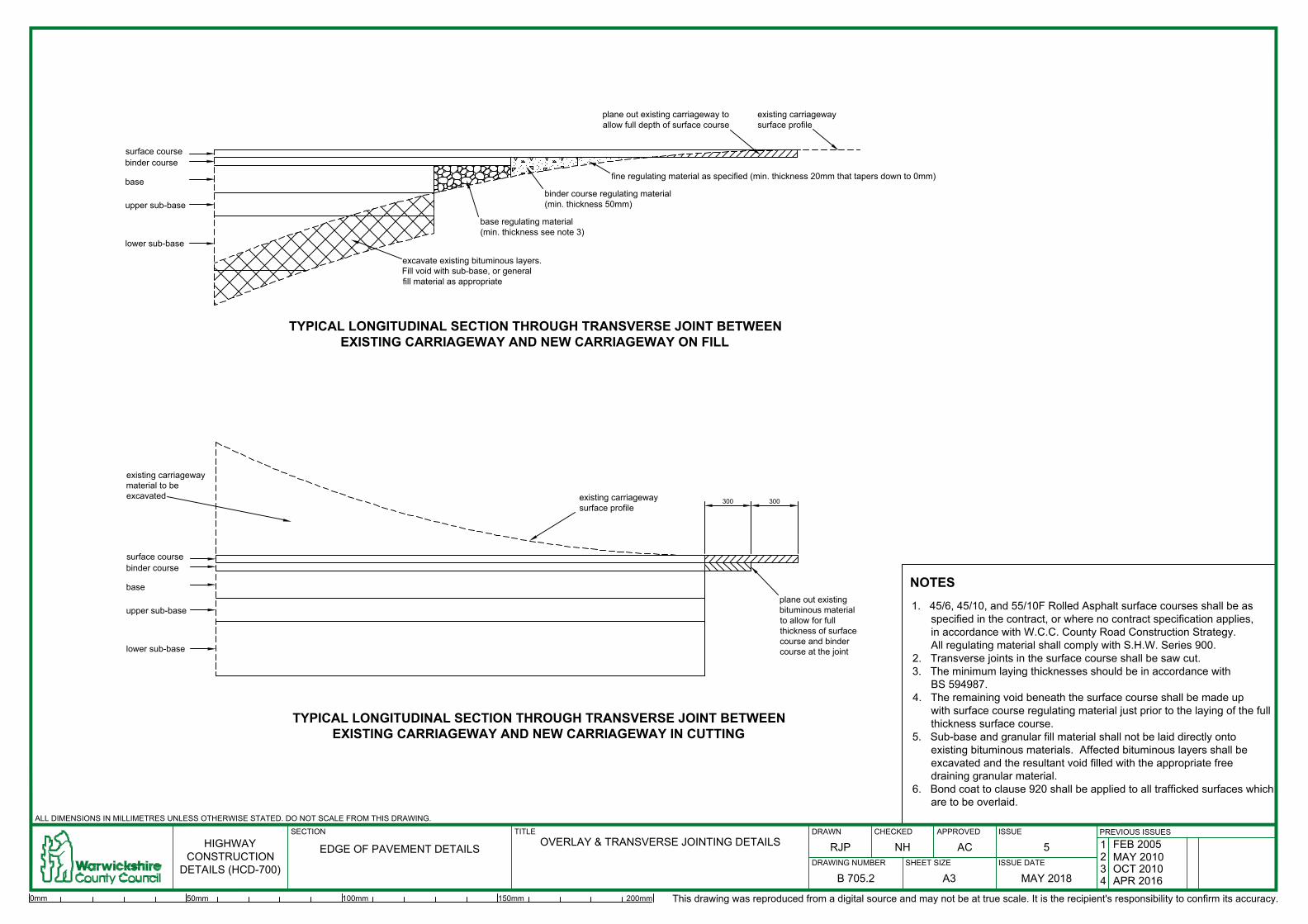
surface course
binder course
base
upper sub-base
lower sub-base
excavate existing bituminous layers.
Fill void with sub-base, or general
fill material as appropriate
base regulating material
(min. thickness see note 3)
binder course regulating material
(min. thickness 50mm)
fine regulating material as specified (min. thickness 20mm that tapers down to 0mm)
plane out existing carriageway to
allow full depth of surface course
existing carriageway
surface profile
TYPICAL LONGITUDINAL SECTION THROUGH TRANSVERSE JOINT BETWEEN
EXISTING CARRIAGEWAY AND NEW CARRIAGEWAY ON FILL
lower sub-base
upper sub-base
base
binder course
surface course
300 300
plane out existing
bituminous material
to allow for full
thickness of surface
course and binder
course at the joint
existing carriageway
surface profile
existing carriageway
material to be
excavated
TYPICAL LONGITUDINAL SECTION THROUGH TRANSVERSE JOINT BETWEEN
EXISTING CARRIAGEWAY AND NEW CARRIAGEWAY IN CUTTING
HIGHWAY
CONSTRUCTION
DETAILS (HCD-700)
DRAWING NUMBER ISSUE DATE
DRAWN CHECKED
ALL DIMENSIONS IN MILLIMETRES UNLESS OTHERWISE STATED. DO NOT SCALE FROM THIS DRAWING.
SHEET SIZE
ISSUEPREVIOUS ISSUES
SECTION TITLE APPROVED
EDGE OF PAVEMENT DETAILS
OVERLAY & TRANSVERSE JOINTING DETAILS
B 705.2
5
MAY 2018A3
RJP NH AC
1 FEB 2005
2 MAY 2010
3 OCT 2010
4 APR 2016
This drawing was reproduced from a digital source and may not be at true scale. It is the recipient's responsibility to confirm its accuracy.
0mm 50mm 100mm 150mm 200mm
1. 45/6, 45/10, and 55/10F Rolled Asphalt surface courses shall be as
specified in the contract, or where no contract specification applies,
in accordance with W.C.C. County Road Construction Strategy.
All regulating material shall comply with S.H.W. Series 900.
2. Transverse joints in the surface course shall be saw cut.
3. The minimum laying thicknesses should be in accordance with
BS 594987.
4. The remaining void beneath the surface course shall be made up
with surface course regulating material just prior to the laying of the full
thickness surface course.
5. Sub-base and granular fill material shall not be laid directly onto
existing bituminous materials. Affected bituminous layers shall be
excavated and the resultant void filled with the appropriate free
draining granular material.
6. Bond coat to clause 920 shall be applied to all trafficked surfaces which
are to be overlaid.
NOTES

Y
750
2000
permanent non-illuminated bollards type: 'Glasdon
Vergemaster' with red/white reflectors or similar
approved by the Overseeing Organisation, evenly
spaced and positioned to achieve a clearance of
450mm from kerb face
existing kerbs to remain or dished
channel dependant on direction of
fall
type 2 footway/cycleway construction
in accordance with B 704.1
kerb type HB2
(refer to kerb base and backing
details on B 702.1)
continuous white line to Diag.
1012.1, 100mm wide offset 100mm
from kerb face of build out and
750mm from existing kerb face
TYPE 1 BUILD OUT
Y
750
TYPE 2 BUILD OUT
r = 1000mm
existing kerbline
r = 305mm
(QHB type kerbs)
45° to carriageway
TYPE 3 BUILD OUT
r = 1000mm
existing kerbline
r = 305mm
(QHB type kerbs)
750
Y
r = 1000mm
1000
permanent non-illuminated bollards
type: 'Glasdon Vergemaster' with
red/white reflectors or similar
approved by the Overseeing
Organisation, evenly spaced and
positioned to achieve a clearance
of 450mm from kerb face
continuous white line to Diag.
1012.1, 100mm wide offset 100mm
from kerb face of build out and
750mm from existing kerb face
kerb type HB2
(refer to kerb base and
backing details on B 702.1)
permanent non-illuminated bollards
type: 'Glasdon Vergemaster' with
red/white reflectors or similar
approved by the Overseeing
Organisation, evenly spaced and
positioned to achieve a clearance
of 450mm from kerb face
type 2 footway/cycleway construction
in accordance with B 704.1
type 2 footway/cycleway construction
in accordance with B 704.1
kerb type HB2
(refer to kerb base and
backing details on B 702.1)
MINIMUM CARRIAGEWAY WIDTH
kerb to kerb distance must be less than 3.1m or greater than 3.9m
22.5° to carriageway
22.5° to carriageway
1100mm minimum if to
accommodate cyclists
HIGHWAY
CONSTRUCTION
DETAILS (HCD-700)
DRAWING NUMBER ISSUE DATE
DRAWN CHECKED
ALL DIMENSIONS IN MILLIMETRES UNLESS OTHERWISE STATED. DO NOT SCALE FROM THIS DRAWING.
SHEET SIZE
ISSUEPREVIOUS ISSUES
SECTION TITLE APPROVED
EDGE OF PAVEMENT DETAILS
BUILD OUTS FOR ROAD NARROWINGS
& CHICANES
B 706.1
3
MAY 2018A3
RJP NH AC
1 APR 2016
2 FEB 2017
1. Road markings shall comprise white thermoplastic screed with applied solid glass beads.
2. The surface profile of Build Outs shall match the profile of the existing carriageway.
3. Dimension 'Y' must not exceed 3.8m.
NOTES
This drawing was reproduced from a digital source and may not be at true scale. It is the recipient's responsibility to confirm its accuracy.
0mm 50mm 100mm 150mm 200mm

100005000 5000
BN2 kerb with 25mm upstandGrassguard 160 or equivalent
permeable concrete pavers with
topsoil infill
3500 m
in.
HB2/SP2 kerb and surround as specified
on scheme drawings and B 702.1
100mm upstand
125mm upstand kerbing installed
to B 702.1
TYPICAL PLAN
TYPICAL CROSS SECTION
BN2 kerb with 25mm upstand
pockets filled with topsoil
and grass seeded
HB2/SP2 kerb and surround as specified
on scheme drawings and B 702.1
25mm kiln dried bedding sand200mm Type 1 sub-base to
S.H.W. Clause 803
100mm min. sub-base
bed below kerb
200
sign diag. 650.1
(see notes 3 & 4)
HIGHWAY
CONSTRUCTION
DETAILS (HCD-700)
DRAWING NUMBER ISSUE DATE
DRAWN CHECKED
ALL DIMENSIONS IN MILLIMETRES UNLESS OTHERWISE STATED.DO NOT SCALE FROM THIS DRAWING.
SHEET SIZE
ISSUEPREVIOUS ISSUES
SECTION TITLE APPROVED
EDGE OF PAVEMENT DETAILS
MAINTENANCE BAY
(WITH PERMEABLE CONCRETE PAVERS)
B 707.1
1
MAY 2018A3
RJP DM AC
This drawing was reproduced from a digital source and may not be at true scale. It is the recipient's responsibility to confirm its accuracy.
0mm 50mm 100mm 150mm 200mm
1. Permeable paving to be Marshalls Grassgaurd 160 unless approved in advance by the
Overseeing Organisation.
2. Topsoil should be filled up to 12mm from the top of the block.
3. Requirement for sign diag. 650.1 'No stopping at any time except authorised vehicles', to
be confirmed with the Overseeing Organisation.
4. Specification for sign diag. 650.1 to be provided by the Overseeing Organisation.
NOTES

X+300 min
X+600 max
X/6 or 100 m
in
X50
300
TYPE S
TYPE S1
X+300 min
X+600 max
X
X/4 or 100 m
in
100
X/4 or 100 m
in
TYPE Y
100
X
X+600 max
X+300 min
150
X/4 or 100 m
in
TYPE Y1
X+300 min
X+600 max
150
X100
X/4 or 100 m
in
TYPE Z
X+300 min
X+600 max
X
150
150
X/4 or 100 m
in
TYPE Z1
X+600 max
X+300 min
X
KEY
underside of
lower sub-base
or formation level
underside of topsoil underside of topsoil underside of topsoil
granular material to S.H.W. Clause 503.3(i)
concrete to S.H.W. Clause 503.3(iii)
granular material Type 1 sub-base to S.H.W. Clause 803
compacted in accordance with Clause 612, table 6/4
method 6
Class 8 material to S.H.W. Clause 503.3(iv)
general fill material to S.H.W. Clause 505.2
JOINT DETAIL FOR PIPE SURROUND ON
TYPE Z AND Z1 DRAINS
concrete surround
joint filler board to S.H.W.
Clause 1015 thickness as
stated in note 4.
C
L L
C C
L
L
C
L
C
L
C
underside of
lower sub-base
or formation level
underside of
lower sub-base
or formation level
HIGHWAY
CONSTRUCTION
DETAILS (HCD-700)
DRAWING NUMBER ISSUE DATE
DRAWN CHECKED
ALL DIMENSIONS IN MILLIMETRES UNLESS OTHERWISE STATED. DO NOT SCALE FROM THIS DRAWING.
SHEET SIZE
ISSUEPREVIOUS ISSUES
SECTION TITLE APPROVED
DRAINAGE
SURFACE WATER DRAINS:
BEDDING & TRENCH DETAILS
F 701.1
3
APR 2016A3
SS RJP AC
1 FEB 2005
2 MAY 2010
This drawing was reproduced from a digital source and may not be at true scale. It is the recipient's responsibility to confirm its accuracy.
0mm 50mm 100mm 150mm 200mm
1. Refer to Appendix 5/1 for pipe and bedding alternatives.
2. Dimension 'X' denotes the external diameter of the pipe.
3. The joint detail for pipe surround on Type Z and Z1 drains is for flexible joints only.
4. For pipes with a nominal diameter below 450mm, the thickness of compressible
joint filler board shall be 18mm. For pipes with a nominal diameter of 450mm or
greater, but not exceeding 1200mm, the thicknes of joint filler board shall be
36mm. For pipes exceeding 1200mm nominal diameter, the thickness of joint
filler board shall be 54mm.
NOTES

Y
TYPE G
TYPE I
Y
TYPE H
Y
Y
TYPE J
Y
TYPE H1
Y
TYPE K
KEY
ground level ground level ground level
ground level ground level ground level
Type A or C filter material to S.H.W. Clause 505 or granular
material to S.H.W. Clause 503.3(i)
concrete to S.H.W. Clause 503.3(iii)
Type B filter material to S.H.W. Clause 505.5 table 5/5
75
X
X/3
X/2
X/2
X/3
75
XX
75
X75
X
75
50
100
X
L
C C
L
C
L
C
L
C
L
C
L
HIGHWAY
CONSTRUCTION
DETAILS (HCD-700)
DRAWING NUMBER ISSUE DATE
DRAWN CHECKED
ALL DIMENSIONS IN MILLIMETRES UNLESS OTHERWISE STATED. DO NOT SCALE FROM THIS DRAWING.
SHEET SIZE
ISSUEPREVIOUS ISSUES
SECTION TITLE APPROVED
DRAINAGE
FILTER DRAINS:
BEDDING & TRENCH DETAILS
SHEET 1
F 702.1
3
APR 2016A3
SS RJP AC
1 FEB 2005
2 MAY 2010
This drawing was reproduced from a digital source and may not be at true scale. It is the recipient's responsibility to confirm its accuracy.
0mm 50mm 100mm 150mm 200mm
1. Refer to Appendix 5/1 for pipe and bedding alternatives.
2. Dimension 'X' denotes the external diameter of the pipe.
3. Pipes shall comply with the requirements for filter drain pipes in S.H.W. table 5/1.
4. Pipes shall be laid with the slots or perforations facing upwards.
5. Minimum drain width Y = X+300 for drains not exceeding 1.5m cover below
finished ground level. Y = X+450 for drains exceeding 1.5m cover below finished
ground level.
NOTES

Y
TYPE L
TYPE Q
(GROUP F8)
Y
TYPE M
Y
300
TYPE R
(GROUP F9A/F9B)
300
TYPE P
(GROUP F7)
KEY
ground level
ground level ground level
underside of lower sub-base (or
underside of upper sub-base if
no lower sub-base specified)
Type A or C filter material to S.H.W. Clause 505 or granular
material to S.H.W. Clause 503.3(i)
concrete to S.H.W. Clause 503.3(iii)
Type B filter material to S.H.W. Clause 505.5 table 5/5
75
X
X/3
X/2
X
75
75
75
100mm internal diameter
UPVC or polypropylene
pipe to BS 4962
formation level
Z2
75
100mm or 160mm internal
diameter UPVC or
polypropylene pipe to BS 4962
600
turf or seeded topsoil in accordance with Appendix 5/1
Z1
L
C C
L
C
L
C
L
C
L
HIGHWAY
CONSTRUCTION
DETAILS (HCD-700)
DRAWING NUMBER ISSUE DATE
DRAWN CHECKED
ALL DIMENSIONS IN MILLIMETRES UNLESS OTHERWISE STATED. DO NOT SCALE FROM THIS DRAWING.
SHEET SIZE
ISSUEPREVIOUS ISSUES
SECTION TITLE APPROVED
DRAINAGE
FILTER DRAINS:
BEDDING & TRENCH DETAILS
SHEET 2
F 702.2
4
MAY 2018A3
RJP NH AC
1 FEB 2005
2 MAY 2010
3 APR 2016
This drawing was reproduced from a digital source and may not be at true scale. It is the recipient's responsibility to confirm its accuracy.
0mm 50mm 100mm 150mm 200mm
1. Refer to Appendix 5/1 for pipe and bedding alternatives.
2. Dimension 'X' denotes the external diameter of the pipe.
3. Pipes shall comply with the requirements for filter drain pipes in S.H.W. table 5/1.
4. Pipes shall be laid with the slots or perforations facing upwards.
5. Minimum drain width Y = X+300 for drains not exceeding 1.5m cover below
finished ground level. Y = X+450 for drains exceeding 1.5m cover below finished
ground level.
6. Depth of Type P filter drain Z1 = lower sub-base layer thickness+300mm. Where
no lower sub-base layer is specified Z1 = 300mm.
7. Depth of Type Q filter drain Z2 = lower sub-base layer thickness+(X+50)mm, or
600mm whichever is the greater. Where no lower sub-base layer is specified
Z2 = 600mm.
8. Group F9B filter drains are the same as Group F9A (shown), except that the filter
material shall continue up to ground level.
NOTES

225 m
in. 375 m
ax.
300
150
150
100
300
600 m
ax.
15 m
in. 50 m
ax.
chamber diameter as specified
225 225
SECTION A-A
SECTION B-B
600
300
500 max.
B
B
A A
PLAN
(see note 9)
mortar bed to chamber top
max. 20mm thick,
min. 10mm thick
brickwork, or seating ring to
BS 5911-3 and BS EN 1917
precast concrete cover slab
bedded on mortar min. 10mm
thick
precast concrete chamber
ring
outlet drain
flow
dimension below lowest pipe
invert
insitu concrete base slab
Class ST4
65mm nominal bore pipe,
600mm long on upstream
side of catchpit (see note 5)
step irons
flexible joint (see note 7)
chamber top
not shown
flow
square opening
Catchpit Type Chamber Diameter (mm) Base Slab Diameter (mm)
A 900 1400
1050
1200
B
C
1550
1700
1350
1500
D
E
1850
2000
insitu concrete
surround Class
ST4
pipe bedding as
specified
L
C
L
C
HIGHWAY
CONSTRUCTION
DETAILS (HCD-700)
DRAWING NUMBER ISSUE DATE
DRAWN CHECKED
ALL DIMENSIONS IN MILLIMETRES UNLESS OTHERWISE STATED. DO NOT SCALE FROM THIS DRAWING.
SHEET SIZE
ISSUEPREVIOUS ISSUES
SECTION TITLE APPROVED
DRAINAGE
PRECAST CONCRETE CATCHPITS
F 703.1
5
MAY 2018A3
RJP NH AC
1 FEB 2005
2 MAY 2010
3 OCT 2010
4 APR 2016
This drawing was reproduced from a digital source and may not be at true scale. It is the recipient's responsibility to confirm its accuracy.
0mm 50mm 100mm 150mm 200mm
1. Precast concrete shall comply with the requirements of BS 59113 and BS EN
1917.
2. Refer to the scheme specific drawings, Appendix 5/1 and the drainage schedule
for invert level, cover level and branch connection details.
3. Mortar shall be designation (i) to S.H.W. Clause 2404.
4. Pipes shall be grouted into catchpits with mortar.
5. 65mm diameter pipes 600mm long shall be built into catchpits to drain the sump
of trenches on upstream connections. Pipes shall be positioned above any
concrete filter drain beds.
6. Positioning of chamber access lids and step irons to be agreed with Overseeing
Organisation.
7. Flexible joints adjacent to pipe connections shall comply with S.H.W. Clause
507.15.
8. Precast concrete catchpit rings shall be of a type manufactured to comprise
sulphate resisting cement to BS 4027: 1996.
9. The chamber top shall be set as dimensioned below the adjacent:
a. hard shoulder or hardstrip (for verges or central reserves on carriageways
without concrete kerbing; and
b. finished ground level in all other off carriageway locations.
Where catchpits are to constructed within the carriageway, the chamber top shall
be set flush with the carriageway surface.
10. Catchpits in new carriageway shall be raised to finished road level following
completion of binder course laying and prior to commencement of surface course
laying, as prescribed by BS 594987:2007 clause 6.9.
11. Brickwork shall be English bond and comprise Class B clay engineering bricks to
BS EN 722-3: 1998 and BS EN 722-7: 1998, bedded on mortar. Brickwork shall
comply with S.H.W. Clauses 2406 and 2412.
12. This detail applies only to those catchpits where the distance between cover level
and catchpit invert level does not exceed 2.0m.
13. Chamber cover and frame to be ductile iron Class D400, non-rocking to
BS EN124:2015 and HA 104/09.
NOTES

1500 - 2500G 1200
not exceeding 1500900F
Chamber Depth (mm)Chamber Length (mm)Catchpit Type
1350 (F
) or 1650 (G
)
825
525(F
) or 825(G
)
1250
825 425
6 no. 16mm dia bars at 138mm c/c
2 no. 20mm dia bars at 145mm c/c
2 no. 16mm dia bars at 145mm c/c (F) or
4 no. 16mm dia bars at 148mm c/c (G)
4 no. 20mm dia bars at 112mm c/c
6 no. 16mm dia bars at 138mm c/c
AA
225
cham
ber length as specified
225
300
600 square
COVER SLAB AND REINFORCEMENT DETAIL
PLAN
225 800 225
150 (all round)
225 800 225
150 (all round)
150
300
225
600 m
ax.
(see note 6)
15 m
in. 50 m
ax.
SECTION A-A
brickwork 225mm wide or seating ring
to BS 5911-3 and BS EN 1917
reinforced concrete cover slab
brickwork
brick arch (one brick width thick) over
pipes exceeding 225mm dia.
insitu concrete base slab Class ST4
invert level 300mm above topside of
base slab
step irons positioned
at 300mm centres
flexible joint
(see note 5)
flexible joint
(see note 5)
flexible joint
(see note 5)
L
C
HIGHWAY
CONSTRUCTION
DETAILS (HCD-700)
DRAWING NUMBER ISSUE DATE
DRAWN CHECKED
ALL DIMENSIONS IN MILLIMETRES UNLESS OTHERWISE STATED. DO NOT SCALE FROM THIS DRAWING.
SHEET SIZE
ISSUEPREVIOUS ISSUES
SECTION TITLE APPROVED
DRAINAGE
BRICK CATCHPITS
F 703.2
5
MAY 2018A3
RJP NH AC
1 FEB 2005
2 MAY 2010
3 APR 2016
4 FEB 2017
This drawing was reproduced from a digital source and may not be at true scale. It is the recipient's responsibility to confirm its accuracy.
0mm 50mm 100mm 150mm 200mm
1. Refer to the scheme specific drawings, Appendix 5/1 and the drainage schedule for invert
level, cover level and branch connection details.
2. Mortar shall be designation (i) to S.H.W. Clause 2404.
3. Pipes shall be grouted into catchpits with mortar.
4. Both chamber top and step irons shall be positioned so that access will allow persons
to face oncoming traffic.
5. Flexible joints adjacent to pipe connections shall comply with S.H.W. Clause 507.15.
6. The chamber top shall be set as dimensioned below the adjacent:
a. hard shoulder or hardstrip (for verges or central reserves on carriageways without
concrete kerbing; and
b. finished ground level in all other locations.
Where catchpits are to constructed within the carriageway, the chamber top shall
be set flush with the carriageway surface.
7. Catchpits in new carriageway shall be raised to finished road level following
completion of binder course laying and prior to commencement of surface course
laying, as prescribed by BS 4987: Part 2 Clause 5.8.
NOTES
8. Brickwork shall be English bond and comprise Class B clay
engineering bricks to BS EN 771-1:2003, bedded on mortar.
Brickwork shall comply with S.H.W. Clauses 2406 and 2412.
9. This detail applies only to those catchpits where the distance
between cover level and catchpit invert level does not exceed
2.5m.
10. On reinforced concrete cover slabs:
a. reinforcement shall be positioned in the tension zone (bottom
of slab) only;
b. concrete shall be grade 40/20, minimum cement content =
325kg/m³, maximum water/cement ratio = 0.5;
c. reinforcement cover shall be 45mm;
d. reinforcement steel bars shall be grade 460 to BS 4449:
2005+A2:2009; and
e. reinforcement steel bars shall be hooked at the ends in
accordance with BS 8666:2005 and BS EN ISO 4066:2000.
11. Chamber cover and frame to be ductile iron Class D400,
non-rocking to BS EN124:2015 and HA 104/09.

PRE-CAST CONCRETE CHANNEL GULLYPRE-CAST CONCRETE KERB INLET GULLY
PLAN
(see note 6)
(see gully type schedule)
1
5
0
d
ia
.
85 m
in.
85 m
in.
1
5
0
d
ia
.
(see note 6)
(see gully type schedule)
chamber top
not shown
edge of kerb
outlet position shall
be detailed on the
scheme specific
contract drawings
'wildlife bypass' kerb
(unless otherwise stated
on scheme drawings)
5m
m recess
mortar bed
10mm thick
min. 20mm
thick max.
brickwork
insitu concrete
Class ST4
150 concrete surround
150 concrete bed
150 concrete surround
150 concrete bed
insitu concrete
Class ST4
brickwork
mortar bed
10mm thick
min. 20mm
thick max.
insitu concrete
haunch Class ST4
Class ST4 insitu
concrete surround
150mm thick min.
brickwork
mortar bed 10mm thick
min. 20mm thick max.
finished
road level
5m
m recess
85 m
in.
1
5
0
d
ia
.
(see gully type schedule)
(see note 6)
PLASTIC GULLY WITH INSITU-CAST
CONRETE SURROUND
450mm min.
diameter above
this level
220 m
in.
400mm min.
diameter above
this level
50
square to circular
conversion section
plastic rising liner cut to
suit depth of brickwork
GULLY TYPE
INTERNAL DIAMETER (mm)
DEPTH OF GULLY POT (mm)
1 2A 2B
450 375 375
900 750 900
gully chamber top
gully chamber top
C
L
L
C
finished
road level
finished
road level
'wildlife bypass' kerb
(unless otherwise stated
on scheme drawings)
HIGHWAY
CONSTRUCTION
DETAILS (HCD-700)
DRAWING NUMBER ISSUE DATE
DRAWN CHECKED
ALL DIMENSIONS IN MILLIMETRES UNLESS OTHERWISE STATED. DO NOT SCALE FROM THIS DRAWING.
SHEET SIZE
ISSUEPREVIOUS ISSUES
SECTION TITLE APPROVED
DRAINAGE
GULLIES:
TYPE 1, 2A & 2B
F 704.1
5
MAY 2018A3
RJP NH AC
1 FEB 2005
2 MAY 2010
3 APR 2016
4 FEB 2017
This drawing was reproduced from a digital source and may not be at true scale. It is the recipient's responsibility to confirm its accuracy.
0mm 50mm 100mm 150mm 200mm
1. Channel gully chamber top shall be grade D400 (BS EN 124).
Kerb inlet gully chamber top shall be grade GK-165 unless
otherwise specified in the contract documents.
2. Precast concrete gullies shall comply with BS 5911:2002/2004.
3. Channel gullies shall be raised to finished road level following
completion of binder course laying and prior to commencement of
surface course laying, as prescribed by BS 594987:2007 clause 6.9.
4. Brickwork shall be English bond and comprise Class B clay
engineering bricks to BS EN 771-1:2003, bedded on mortar.
Brickwork shall comply with S.H.W. Clauses 2406 and 2412.
Brickwork may require corbelling depending on the type of pot and
frame.
5. Mortar shall comply with S.H.W. Clause 2404 designation (i).
6. The minimum depth from the top of kerb (on channel gullies) or
over level (on kerb inlet gullies) to the soffit level of the gully outlet
shall be 750mm when the connecting pipe is below carriageway (or
hardshoulder), and 600mm elsewhere.
7. The stoppers on trapped insitu cast gullies shall comply with the
requirements of BS 5911:2002/2004.
8. Gully connections under carriageway shall comply with the
requirements of either Pipe Group S7 or S8 depending on depth of
cover. Gully connections within 4m of the carriageway shall
comply with the requirements of Pipe Group S2. Gully connections
in all other locations shall comply with the requirements of Pipe
Group S3. Refer to Notes for Guidance Annex 1, or Appendix 5/1
for pipe group details.
9. Refer to the schedule below for gully types.
10. Plastic gullies with insitu-cast concrete surrounds may be used for
channel gullies (as shown), or for kerb inlet gullies, at the discretion
of the Overseeing Organisation.
NOTES

verge width as specified
6
0
0
m
in
.
1
5
0
m
m
d
ia
.
p
ip
e
drain as specified
Group S3 drain
group S2 drain
GULLY CONNECTION DETAIL
RODDING EYE DETAIL RODDING EYE COVER DETAIL
600 square
100
500
300mm x 300mm locking
access chamber top,
grade A in accordance with
BS 5834: Part 2, bedded
centrally over the rodding eye
pipe on mortar 10mm thick
surrounded by concrete
Class ST4 100mm thick
drainage systemrodding eye
45° bend
tapered section
(where necessary)
150mm dia rodding eye connection
pipe of similar type and strength to
downstream drainage system
bends where
necessary
connection to F 707.1
HIGHWAY
CONSTRUCTION
DETAILS (HCD-700)
DRAWING NUMBER ISSUE DATE
DRAWN CHECKED
ALL DIMENSIONS IN MILLIMETRES UNLESS OTHERWISE STATED. DO NOT SCALE FROM THIS DRAWING.
SHEET SIZE
ISSUEPREVIOUS ISSUES
SECTION TITLE APPROVED
DRAINAGE
GULLY CONNECTIONS & RODDING EYES
F 704.2
4
MAY 2018A3
RJP NH AC
1 FEB 2005
2 MAY 2010
3 APR 2016
This drawing was reproduced from a digital source and may not be at true scale. It is the recipient's responsibility to confirm its accuracy.
0mm 50mm 100mm 150mm 200mm
1. Where gullies discharge into an open ditch, a Type 3 headwall
shall be constructed at the outfall. Refer to F 705.1 for details.
2. Mortar shall comply with S.H.W. Clause 2404
designation (i).
NOTES

TYPE 1 - INLET HEADWALL
A
A
insitu concrete class ST4
precast concrete
paving flags 63mm
thick
H
X
7
5
2H + X
10
0 m
in
.
ELEVATION
SECTION A-A
15
0
1400
50
0
1000 min.
insitu concrete
grade C32/40
pipe bedding
as specified
TYPE 3 - INTERMEDIATE HEADWALL
C
C
section through
ditch invert
ELEVATION
SECTION C-C
insitu concrete grade 32/40
pipe bedding as
specified
900 or D + 300 (whichever is the greater)
15
0
D
10
0 m
in
.
3
0
0
m
i
n
.
7
5
X
insitu concrete class ST4
SECTION D-D
ELEVATION
section through
ditch invert
D
D
DITCH LINING DETAIL
X
H
15
0
1
0
0
600mm x 600mm
x 63mm precast
concrete paving
flags
SECTION B-B
PLAN
TYPE 2 - OUTLET HEADWALL
water level
B
B
flow
river bed
22
5
17
5
150
25
0
revetment in
precast
concrete
blocks
1
5
0
1
5
0
1
5
0
width and gradient of river bank varies
concrete
fillet
insitu concrete
grade 32/40
pipe bedding
as specified
1:1 Slope
650
40
0
250
25
0
masonry ties at
300c/c vertically
400c/c horizontally
masonry ties at
300c/c vertically
400c/c horizontally
150
20 mm half round drip
concrete coping
reinforcement mesh type A393 to
BS 4483:2005 with 60mm cover
reinforcement mesh type A393 to
BS 4483:2005 with 60mm cover
20 mm half
round drip
concrete coping
HIGHWAY
CONSTRUCTION
DETAILS (HCD-700)
DRAWING NUMBER ISSUE DATE
DRAWN CHECKED
ALL DIMENSIONS IN MILLIMETRES UNLESS OTHERWISE STATED. DO NOT SCALE FROM THIS DRAWING.
SHEET SIZE
ISSUEPREVIOUS ISSUES
SECTION TITLE APPROVED
DRAINAGE
HEADWALLS: TYPE 1, 2 & 3
WITH DITCH LINING DETAIL
F 705.1
4
APR 2016A3
SS RJP AC
1 FEB 2005
2 MAY 2010
3 APR 2014
This drawing was reproduced from a digital source and may not be at true scale. It is the recipient's responsibility to confirm its accuracy.
0mm 50mm 100mm 150mm 200mm
1. Headwall dimensions:
a. H = height of headwall from outfall invert level to top of parapet;
b. X = width of ditch invert; and
c. D = internal diameter of pipe.
2. The maximum height 'H' is 1200mm for Type 1 and 2 Headwalls.
3. Refer to drainage schedule in Appendix 5/1 or scheme specific contract drawings for pipe diameter and ditch side slope gradient.
4. Concrete finishes shall comply with S.H.W. Clause 2602
5. Brickwork shall be English bond and comprise Class B clay engineering bricks to BS EN 771-1:2011, bedded on mortar.
6. Brickwork shall comply with S.H.W. Clauses 2406 and 2412.
7. Mortar shall comply with S.H.W. Clause 2404 designation (i).
8. The nearest pipe joint on pipes where diameter 'D' is greater than 375mm shall be no more than 1m from the outer face of the headwall.
9. Refer to drainage schedule in Appendix 5/1 or scheme specific contract drawings for pipe diameter and ditch side slope gradient.
10. Precast concrete paving flags shall comply with BS EN 1339:2003.
11. On Type 2 headwalls, the angle between outfall pipe and direction of flow on the watercourse shall be 45° unless otherwise directed by the Overseeing Organisation.
12. The Environment Agency's approval is required where Type 2 headwalls discharge into natural watercourses.
13. All pipe sections built into headwalls shall be either vitrified clay or concrete. Refer to Table 1 in Notes for Guidance Annex 1 for details of acceptable pipe materials.
NOTES

6
0
0
m
in
.
drain as specified
CONNECTION OF EXISTING LAND DRAIN
TO NEW FILTER DRAIN
bends where
necessary
750 m
in.
3% min.
existing land drainnew drain
200 min.
severed land drain
to be removed
severed land drain
to remain
DETAIL SHOWING LAND DRAIN SEALED
DOWNSTREAM OF FILTER DRAIN
seal with insitu concrete
Class ST2
connection to F 707.1
connection to F 707.1
HIGHWAY
CONSTRUCTION
DETAILS (HCD-700)
DRAWING NUMBER ISSUE DATE
DRAWN CHECKED
ALL DIMENSIONS IN MILLIMETRES UNLESS OTHERWISE STATED. DO NOT SCALE FROM THIS DRAWING.
SHEET SIZE
ISSUEPREVIOUS ISSUES
SECTION TITLE APPROVED
DRAINAGE
CONNECTION OF PERMANENTLY
SEVERED LAND DRAINS
F 706.1
4
MAY 2018A3
RJP NH AC
1 FEB 2005
2 MAY 2010
3 APR 2016
This drawing was reproduced from a digital source and may not be at true scale. It is the recipient's responsibility to confirm its accuracy.
0mm 50mm 100mm 150mm 200mm
1. Jointed perforated or slotted pipes (UPVC, concrete or vitrified clay) may
be used as an alternative.
2. Pipe haunches and surrounds shall comply with S.H.W. Clause 503.3 (v).
3. The internal diameter of new pipes downstream of the connection point
shall be no less than the internal diameter of the existing land drain.
4. Pipes shall be laid with open joints and bedded on the bottom of the
trench. Backfill shall be Class 1, 2A, 2B or 2C material in accordance
with S.H.W. Table 6/1 overlaid with topsoil as specified.
NOTES

300
225
225
150
150100
Min. Main Pipe Dia. (mm)Minor Pipe Dia. (mm)
ELEVATION/SECTION
(SQUARE SADDLE)
ELEVATION/SECTION
(45° OBLIQUE SADDLE)
150
150
4
5
°
Class ST4 concrete
bed and surround
SECTION A-A
Permitted Connections
300 375
flow
600 min.
A
A
600 min.
flow
saddles shall be
bonded to the main
pipe with mortar
saddles shall be
bonded to the main
pipe with mortar
HIGHWAY
CONSTRUCTION
DETAILS (HCD-700)
DRAWING NUMBER ISSUE DATE
DRAWN CHECKED
ALL DIMENSIONS IN MILLIMETRES UNLESS OTHERWISE STATED. DO NOT SCALE FROM THIS DRAWING.
SHEET SIZE
ISSUEPREVIOUS ISSUES
SECTION TITLE APPROVED
DRAINAGE
CONCRETE PIPE SADDLES
F 707.1
4
MAY 2018A3
RJP NH AC
1 FEB 2005
2 MAY 2010
3 APR 2016
This drawing was reproduced from a digital source and may not be at true scale. It is the recipient's responsibility to confirm its accuracy.
0mm 50mm 100mm 150mm 200mm
1. Mortar shall comply with S.H.W. Clause 2404 designation (i).
2. Pipe connections shall be inspected by the Overseeing Organisation
prior to the placing of concrete saddles.
3. On connections where the main pipe is of a vitrified clay type not
exceeding 225mm diameter, a length of pipe shall be cut out and
replaced by a manufactured 'sleeve' type junction. The sleeve
couplings, with their central register removed, shall be used to form
a slip ring to enable the junction to be jointed to the main pipe.
4. Junction pipes should be of the type and class of material as the
main pipe.
5. Junction pipes not immediately connected should be sealed in
accordance with SHW Clause 508.
NOTES

1000highway
600
cultivated
topsoil strip
225
centreline of hedge =
highway boundary
SECTION A-A
(UNDISTURBED GROUND)
SECTION A-A
(DISTURBED GROUND)
centreline of hedge =
highway boundary
cultivated
topsoil strip
600
highway 1000
450
300
1000
X Y
A
A
BOUNDARY HEDGE
PLANTING DETAILS
centreline of hedge =
highway boundary
fenceline
centreline of hedge =
highway boundary
6
0
°
1000
BOUNDARY HEDGE
DETAIL AT FIELD GATE
HIGHWAY
CONSTRUCTION
DETAILS (HCD-700)
DRAWING NUMBER ISSUE DATE
DRAWN CHECKED
ALL DIMENSIONS IN MILLIMETRES UNLESS OTHERWISE STATED. DO NOT SCALE FROM THIS DRAWING.
SHEET SIZE
ISSUEPREVIOUS ISSUES
SECTION TITLE APPROVED
FENCES, STILES AND GATES
BOUNDARY HEDGE
H 701.1
3
APR 2016A3
SS RJP AC
1 FEB 2005
2 MAY 2010
This drawing was reproduced from a digital source and may not be at true scale. It is the recipient's responsibility to confirm its accuracy.
0mm 50mm 100mm 150mm 200mm
1. Dimension 'X' shall be 600mm and dimension 'Y' shall
be 300mm unless specified otherwise by the
Overseeing Organisation.
2. The cultivated topsoil strip shall be maintained free
from weeds for a period of 3 years following
completion of hedge planting.
3. In rural areas, hedge plant species shall be selected
from those listed in the 'Warwickshire Landscape
Guidelines' document for the particular geographic
region that the hedge is to be planted. Copies of
these documents are available for inspection upon
request.
NOTES

SECTION A-A
2100
700
750
400
300
insitu concrete
Class ST2
backfill
material
315
2850
225
225
250
250
post (150mm x 75mm)
in concrete footing
prick post (1800mm
x 87mm x 38mm)
rails (87mm x 38mm)
nailed to posts
TIMBER POST AND FOUR
RAIL FENCE
A
A
backfill
material
insitu concrete
Class ST2
300
SECTION B-B
1000
450
500
300
60
100
400
2000
B
B
TIMBER POST AND TWO
RAIL FENCE
2 no. 150mm x 10mm dia. round
headed galvanised steel bolts
with galvanised steel washers
and hexagonal nuts
30mm x 3mm galvanised steel
plate straps drilled to take 10mm
dia. bolts
80mm x 80mm timber rail lap
jointed at the post
75mm x 40mm morticed timber
rail scarf jointed at the post
115mm x 115mm
timber post
115
115
DETAIL OF SAWN LAP JOINT
FOR TIMBER TOP RAIL
Carriageway side
HIGHWAY
CONSTRUCTION
DETAILS (HCD-700)
DRAWING NUMBER ISSUE DATE
DRAWN CHECKED
ALL DIMENSIONS IN MILLIMETRES UNLESS OTHERWISE STATED. DO NOT SCALE FROM THIS DRAWING.
SHEET SIZE
ISSUEPREVIOUS ISSUES
SECTION TITLE APPROVED
FENCES, STILES AND GATES
FENCING: TIMBER POST AND RAIL
H 702.1
4
MAY 2018A3
RJP NH AC
1 FEB 2005
2 MAY 2010
3 APR 2016
This drawing was reproduced from a digital source and may not be at true scale. It is the recipient's responsibility to confirm its accuracy.
0mm 50mm 100mm 150mm 200mm
1. Fencing shall comply with S.H.W. Series 300 and
BS 1722-7: 2006, except where contradicted by this
construction detail.
2. Excavations for post footings shall have vertical sides,
unless specified otherwise by the Overseeing Organisation.
3. Backfill shall be Class 1, 2A, 2B or 2C material in accordance
with S.H.W. Table 6/1 overlaid with topsoil as specified.
4. Timber shall comply with S.H.W. Clause 304.
5. Prick posts shall be driven.
6. Rails for timber post and four rail fences shall be nailed (two no.
nails per joint) to the post face facing away from the
carriageway. Nails shall be galvanised.
7. Details of additional fencing fixtures are given in Appendix 3/1.
NOTES

50
650
75
50
80
1270
1375
2100
460
90
75
100
50
a
170
170
170 GATE TYPE DIMENSION 'a' (mm)
1 3000
2 3600
3 4200
200 x 200 x 2100 longhanging post
DIMENSIONS (mm)DESCRIPTION OF TIMBER MATERIALS
shutting post 175 x 175 x 2100 long
hanging stile 100 x 75 for gate Type 1
125 x 75 for gate Types 2 and 3
shutting stile 75 x 75
top rail 100 x 75 for gate Type 1
125 x 75 for gate Types 2 and 3
(all tapering to 75 x 75)
under rails 75 x 75
braces (housed in top rail) 75 x 75
170
170
170
e
d
50
100
75
90
460
2100
1375
1270
80
50
75
650
50
TIMBER SINGLE FIELD GATE
TIMBER DOUBLE FIELD GATE
TIMBER DOUBLE FIELD GATE
TIMBER SINGLE FIELD GATE
410042003
350036002
290030001
DIMENSION 'e' (mm)DIMENSION 'd' (mm)GATE TYPE
DIMENSION 'c' (mm)
1200, 1625, or 3000
1200, 1625, 3000, or 3600
1200, 1625, 3000, 3600, or 4200
b
c
10
insitu concrete Class ST2
insitu concrete Class ST2
fish tailed bolt socket set in
300mm x 300mm x
300mm insitu concrete
surround Class ST2 and
U2 finish
Note: d=(e+100)mm
Note: b=(a+c+60)mm
HIGHWAY
CONSTRUCTION
DETAILS (HCD-700)
DRAWING NUMBER ISSUE DATE
DRAWN CHECKED
ALL DIMENSIONS IN MILLIMETRES UNLESS OTHERWISE STATED. DO NOT SCALE FROM THIS DRAWING.
SHEET SIZE
ISSUEPREVIOUS ISSUES
SECTION TITLE APPROVED
FENCES, STILES AND GATES
TIMBER FIELD GATES: TYPE 1, 2 & 3
H 703.1
4
MAY 2018A3
RJP NH AC
1 FEB 2005
2 MAY 2010
3 APR 2016
This drawing was reproduced from a digital source and may not be at true scale. It is the recipient's responsibility to confirm its accuracy.
0mm 50mm 100mm 150mm 200mm
1. Gates shall comply with BS 3470: 1975 where appropriate, the relevant
clauses of S.H.W. Series 300, and any additional requirements listed in
Appendix 1/15 or 3/1.
2. All through tenons shall be pegged with 13mm dia. oak dowels.
3. On timber single field gates, hangings and fastenings shall comply with
MCHW HCDs H30 and H31 respectively. On timber double field gates
hangings and fastenings shall comply with MCHW HCDs H30 and H32
respectively.
4. Timber shall comply with S.H.W. Clause 304.
5. Gates shall be hung as shown for self closing gates with a self latching
stop post. Refer to MCHW HCD H33 for details.
6. Gates shall orientated to open into the land owner's property.
7. Where dimension 'c' for the additional gate on timber double field gates is
3000mm or less, the hanging stile and top rail dimensions shall match
those for Type 1 gates.
8. Drop bolts and catches on double field gates shall be galvanised in
accordance with BS EN ISO 1461: 2009
NOTES

100
100
100
100
100 100 100100100100
150 m
in. (see note 6)
b
a a
300
b
surfacing & binder
base
upper sub-base
GROUP D1
GROUP D2
formation level
(see note 6)
granular material to S.H.W. Clause 503.3(i)
concrete to S.H.W. Clause 503.3(iii)
Class 8 material to S.H.W. Clause 503.3(iv)
general fill material to S.H.W. Clause 505.2
topsoil (where specified)
KEY
350
yellow polythene identification
tape 150mm x 10 gauge marked
'DUCT BELOW' or otherwise in
accordance with the requirements
of the Service Authority
150
sand protection
150 150
75 m
in.
150
varies
type 1 sub-base material
SERVICE PROTECTION
UNDER CARRIAGEWAY
formation level ground level
SERVICE PROTECTION
UNDER VERGE
150
75 m
in.
150150
150
varies
500 625
SECTION ALONG SERVICE DUCT
footway
filter drain as
specified
see note 8
for duct limits
see note 8
for duct limits
200
c
HIGHWAY
CONSTRUCTION
DETAILS (HCD-700)
DRAWING NUMBER ISSUE DATE
DRAWN CHECKED
ALL DIMENSIONS IN MILLIMETRES UNLESS OTHERWISE STATED. DO NOT SCALE FROM THIS DRAWING.
SHEET SIZE
ISSUEPREVIOUS ISSUES
SECTION TITLE APPROVED
UNDERGROUND CABLE DUCTS
NEW SERVICE DUCTS &
PROTECTION OF EXISTING SERVICES
I 701.1
5
MAY 2018A3
RJP NH AC
1 FEB 2005
2 MAY 2010
3 FEB 2013
4 APR 2016
This drawing was reproduced from a digital source and may not be at true scale. It is the recipient's responsibility to confirm its accuracy.
0mm 50mm 100mm 150mm 200mm
1. Ducts shall be manufactured from, UPVC or a suitable alternative
material specified by the relevant Service Authority.
2. Refer to Appendix 5/2 for details of permissible alternative materials.
3. Dimension 'a' represents the external diameter of the duct.
4. Dimension 'b' represents the minimum cover requirement of the
relevant Service Authority. Dimension 'b' shall be no less than
650mm in the carriageway or 450mm in the footway/verge.
5. Dimension 'c' represents the design thickness of base. Dimension 'c'
shall be no less than 100mm.
6. Concrete protection on Group D1 ducts shall extend up to formation
level and achieve a minimum thickness of 150mm.
7. Upper sub-base shall be Type 1 Unbound Mixtures to S.H.W
Clause 803, Type 2 Unbound Mixtures (if they contain at least 80%
bituminous planings) to S.H.W Clause 804 or Type 3 (open graded)
Unbound Mixtures to S.H.W Clause 805.
8. Where no lower sub-base layer is specified, the upper surface of
concrete protection on Group D1 ducts shall be flush with
sub-formation level.
9. Group D1 ducts shall extend to the edge of capping layer where no
filter drain is specified, otherwise 500mm beyond the filter drain or to
the back of footway (where specified), whichever is the greater
dimension.
10. Refer to MCHW HCD I1 for marker block details.
11. The minimum clearance between the outer surface of ducts and
existing drains, service apparatus and the like shall be 100mm.
12. Refer to Appendix 5/2 and/or the scheme specific drawings for duct
numbers, duct configurations, duct diameters and duct locations. The
same principles shown in this detail for two-way ducts apply to
multi-way duct configurations.
NOTES

TYPICAL SECTION THROUGH
ACCESS CHAMBER
PLAN VIEW SHOWING DUCTS
ENTERING CHAMBER
12mm LDPE base
with pre-drilled
100mm soakaway
varies (see note 2)
extra deep
galvanised
steel frame
(see note 3)
B125 composite cover
backfill insitu
concrete surround
class ST4
150
150
reinstatement of paved
areas (note 9) or verge
condition (note 10)
insitu
concrete
surround
class ST4
raising
sections
100mm drainage duct
duct entry
sections
rising
frame
155
155
155
155
150
fixing point to secure
rising frame to chamber
150150
80
varies (see note 2)
insitu
concrete
surround
class ST4
1
1
4
varies (see note 2)
HIGHWAY
CONSTRUCTION
DETAILS (HCD-700)
DRAWING NUMBER ISSUE DATE
DRAWN CHECKED
ALL DIMENSIONS IN MILLIMETRES UNLESS OTHERWISE STATED. DO NOT SCALE FROM THIS DRAWING.
SHEET SIZE
ISSUEPREVIOUS ISSUES
SECTION TITLE APPROVED
UNDERGROUND CABLE DUCTS
ACCESS CHAMBERS FOR SERVICE DUCTS
I 702.1
4
MAY 2018A3
RJP NH AC
1 FEB 2005
2 MAY 2010
3 APR 2016
This drawing was reproduced from a digital source and may not be at true scale. It is the recipient's responsibility to confirm its accuracy.
0mm 50mm 100mm 150mm 200mm
NOTES
1. Units shall be NAL 'STAKKAbox' type unless approved in advance
by the Overseeing Organisation.
2. Internal opening dimensions shall be 300mm x 300mm (Type 3),
450mm x 450mm (Type 2), 600mm x 450mm (Type 1) or 600mm x
600mm (Type 0) as specified on the scheme specific drawings.
3. The frame type shall be EN 124 B125 black antislip composite cover
(SRV > 80). Frame shall be galvanised steel raising frame provide
with 85 mm bedding depth for surrounding surface course to frame
flange. The frame shall be fixed to the chamber wall with 4 x 8mm
coach bolt.
4. All composite lids to be secured by fixing screws on completion.
5. Pre-formed ring sections may be added to achieve minimum duct
cover as specified in key on scheme specific drawings.
6. Maximum chamber depth under ground to be 885mm
(5 x 155mm + 110mm).
7. All empty access holes must be filled with matching plugs.
8. Sections shall NOT be cut out to accommodate additional ducts.
Contact Overseeing Organisation for advice.
9. Refer to B 704.1 for details.
10. Insitu concrete to be continued to ground level in verge condition,
with U2 finish.

75
75
75
75
350
150
210
60
40
lower
sub-base
upper sub-base
base
binder course
existing road surface
pipe/duct bedding and
backfill as specified
trench width as specified
surface course (see note 6)
TYPE 1 DETAIL TYPE 2 DETAIL
trench width as specified
pipe/duct bedding and
backfill as specified
existing road surface
binder course
base
60
210
150
350
75
75
75
TYPE 3 DETAIL
trench width as specified
pipe/duct bedding and
backfill as specified
existing road surface
base
210
150
350
75
75
TYPE 4 DETAIL
surface course (see note 6)
trench width as specified
pipe/duct bedding and
backfill as specified
existing road surface
binder course
cement bound
material Class
CBM 3
75
75
75
existing surface of
paved area
pipe/duct bedding and
backfill as specified
trench width as specified
surface course
TYPE 5 DETAIL
(PAVED AREAS)
40
60
450
75
footway or cycleway
construction as specified
varies
varies
lower
sub-base
upper sub-base
lower
sub-base
upper sub-base
HIGHWAY
CONSTRUCTION
DETAILS (HCD-700)
DRAWING NUMBER ISSUE DATE
DRAWN CHECKED
ALL DIMENSIONS IN MILLIMETRES UNLESS OTHERWISE STATED. DO NOT SCALE FROM THIS DRAWING.
SHEET SIZE
ISSUEPREVIOUS ISSUES
SECTION TITLE APPROVED
MISCELLANEOUS
TRENCH REINSTATEMENT IN CARRIAGEWAYS
& PAVED AREAS
K 701.1
3
APR 2016A3
SS RJP AC
1 FEB 2005
2 MAY 2010
This drawing was reproduced from a digital source and may not be at true scale. It is the recipient's responsibility to confirm its accuracy.
0mm 50mm 100mm 150mm 200mm
1. Pavement materials shall be as specified in Appendix 7/1, or where no
contract specification applies, in accordance with W.C.C. County
Road Construction Strategy.
2. Longitudinal joints in the surface course shall be saw cut.
3. In narrow trenches where bituminous materials cannot be adequately
compacted, cement bound material (Class CBM 3) shall be used in lieu
of granular sub-base, bituminous base and binder course material as
appropriate.
4. For measurement purposes, the trench width shall be the minimum
permitted for the specified type of drain, duct or other service.
5. Where applicable, alterations to the thickness of materials will be
detailed in Appendix 7/2.
6. Where hot rolled asphalt surface courses are specified, the thickness
of surface course may be increased up to a maximum of 50mm. In this
instance, the thickness of binder course will be reduced to 50mm.
NOTES

2000 POST CTRS (refer to note 3)
900
250
300
400
TYPE PANEL PANEL LAYOUT OPTIMUM SIGHT ANGLE
2
3
V2
V4
V8
2.5° - 5.0°
5.0° - 14.0°
exceeding 14.0°
4
TYPE 1 PEDESTRIAN GUARDRAIL LAYOUT
concrete class ST2
INFILLS:
12X12mm Sq
RAILS:
70x8 RSF
ground level
50x50 RHS
1300
50x10 RSF FLATS
STANDARD TYPES
1not applicable
as shownstandard
70
USAGE
for use on straight roads with
moderate to high speeds
general
for us on straight roads with low to
moderate speeds and curves
for use on curves with a 15m
radius or less
footway surface and
binder course to B 704.1
footway surface and
binder course to B 704.1
100
205
52
52
336
450
300
RS 50X50 SOCKETED OPTION
ST5 concrete
footway surface and
binder course to B 704.1
150
HIGHWAY
CONSTRUCTION
DETAILS (HCD-700)
DRAWING NUMBER ISSUE DATE
DRAWN CHECKED
ALL DIMENSIONS IN MILLIMETRES UNLESS OTHERWISE STATED. DO NOT SCALE FROM THIS DRAWING.
SHEET SIZE
ISSUEPREVIOUS ISSUES
SECTION TITLE APPROVED
MISCELLANEOUS
PEDESTRIAN GUARDRAILS
K 702.1
4
MAY 2018A3
RJP NH AC
1 FEB 2005
2 MAY 2010
3 APR 2016
This drawing was reproduced from a digital source and may not be at true scale. It is the recipient's responsibility to confirm its accuracy.
0mm 50mm 100mm 150mm 200mm
NOTES
1. Guardrailing to be Alpha Rail Ltd. 'Optirail' or similar
approved.
2. Pedestrian guardrails shall be of steel manufacture
and have a hot dip galvanised black finish (RAL 9005).
3. Shorter panels may be used subject to approval from
the Overseeing Organisation.
4. Infilling panels (not 'Optirail') shall consist of vertical
bars.
5. Pedestrian guardrail shall be set back from the kerb
face 450mm (min.) 600mm (max.).
6. V2, V4 and V8 panels refer to the range of 'Optirail'
panel alternatives.
7. The need for non-standard parts to overcome tight
horizontal radii or steep vertical gradients shall be
determined from the scheme specific drawings.
8. The posts and panels shall be separate units.
9. Where pedestrian guardrail is to be fixed to the top of a
concrete wall to act as a parapet, anchorage and fixing
details will be shown on scheme specific drawings.
10. For maintenance reasons RS 50x50 sockets may be
required. This will be at the discretion of the Overseeing
Organisation.

PEDESTRIAN REFUGE
WITH MAINS POWERED
BOLLARDS AND SIGNS
back of footway
kerb type HB2 kerb type DR1 kerb type BN3 kerb type DL1 kerb type HB2
footway regraded
to follow profile of
dropper kerbs
and paving flags
gradient to be no
steeper than 1:20
duct crossing
(see note 7)
125
kerb type HB2
(radius 2000mm)
kerb type HB2
(radius 2000mm)
tactile blister pavingquadrant type QHB
(radius 305mm)
kerb type HB2
(straight)
footway construction
(see note 4)
2000 (1500 m
in.)
2100
retention socket system
(refer to detail)
footway construction
(see note 4)
kerb type HB2
(straight)
quadrant type QHB
(radius 305mm)
kerb type HB2
(radius 2000mm or 1000mm
where refuge is minimum width)
3815 (3430 min.)
1500 (1200 m
in.)
REFUGE WITH MAINS POWERED
BOLLARDS AND SIGNS
duct crossing
(see note 7)
2600 (2300 min.) 2800 (2400 min.) 2600 (2300 min.)
tactile blister paving
HB2 kerb
type DL1
transition kerb
type BN3 kerb cut to
form parallel joint with
adjacent kerb
BN3 kerb (laid
as transition)
BN3 kerbs
BN3 kerb (laid
as transition)
type DR1
transition kerb
HB2 kerb
carriageway laid flush to top of BN3 kerb,
tolerance +0 / -6mm. ie carriageway
cannot be above top of kerb
refuge beacon to be Simmonsigns
LED Modubel, white in colour, in
accordance with Chapter 4 Fig 23.1
of the Traffic Signs Manual
2 no. 600mm Dia. internally
Lit LED Simmonsigns Invinca
to sign diag. 610
retention socket system
(refer to detail)
mains powered bollard
(refer to K 703.7)
2100
KERB DETAILS TO ACHIEVE
GRADIENT OF 1:11 OR FLATTER
2 no. 600mm Dia. internally
Lit LED Simmonsigns Invinca
to sign diag. 610
refuge beacon to be Simmonsigns
LED Modubel, white in colour, in
accordance with Chapter 4 Fig 23.1
of the Traffic Signs Manual
pole banding in accordance with
Chapter 4 Fig 23.1 of the Traffic
Signs Manual
pole banding in
accordance with
Chapter 4 Fig 23.1
of the Traffic Signs
Manual
380
850*
mains powered bollard
(refer to K 703.7)
*1300mm if
installed in
existing
carriageway
construction
material
RS140 RETENTION SOCKET SYSTEM
WITH TEE BASE OR SIMILAR APPROVED
insitu concrete
surround class ST5
kerb type BN3
(0-6mm upstand)
footway
(see note 4)
70
100
access chamber
access chamber (see note 10)
600
HIGHWAY
CONSTRUCTION
DETAILS (HCD-700)
DRAWING NUMBER ISSUE DATE
DRAWN CHECKED
ALL DIMENSIONS IN MILLIMETRES UNLESS OTHERWISE STATED. DO NOT SCALE FROM THIS DRAWING.
SHEET SIZE
ISSUEPREVIOUS ISSUES
SECTION TITLE APPROVED
MISCELLANEOUS
TYPE 1 REFUGES & PEDESTRIAN REFUGES:
WITH MAINS POWERED BOLLARDS & SIGNS
K 703.1
4
APR 2016A3
SL RJP AC
1 FEB 2005
2 MAY 2010
3 OCT 2010
This drawing was reproduced from a digital source and may not be at true scale. It is the recipient's responsibility to confirm its accuracy.
0mm 50mm 100mm 150mm 200mm
NOTES
1. Refer to B 702.1 for kerbing details.
2. Dropper kerb Types DR1 and DL1 shall be cut to form a
vertical joint with adjacent Type HB2 kerbs.
3. Type BN3 kerbs shall be laid with a maximum upstand of
6mm above carriageway.
4. Refuge islands shall be of Type 1 footway construction.
Refer to B 704.1 for details.
5. Tactile blister paving shall be buff in colour, unless stated
otherwise, and shall comprise 400mm x 400mm x 50mm
precast concrete paving bedded on 25mm moist
sand/cement mortar (3:1), joints filled with 4:1 mix to within
2mm of the paving surface. Paving shall be Type A as
defined in Fig. 2 of the Department of Transport's
'Guidance on the use of Tactile Paving Surfaces'.
6. Alternative proposals to the pole mounting system shown
on this detail shall be approved in advance by the
Overseeing Organisation.
7. Duct crossing shall comprise 1 No. 100mm internal
diameter high density polyethylene, smooth single wall
orange service duct, across carriageway in concrete
surround with drawcord (minimum cover 600mm). Refer to
I 701.1, Notes for Guidance Annex 1 and Appendix 5/2 for
duct group details.
8. For details on mains powered bollards see drawing
K 703.7
9. Pedestrian refuges narrower than 2000mm shall only be
provided in locations where the full 2000mm cannot be
achieved.
10. Access chamber units shall be NAL 300x300mm
STAKKAbox unless approved in advance by the
Overseeing Organisation. Refer to I 702.1 for details.
11. The frame type shall be EN 124 B125 black anti-slip
composite cover. Frame shall be galvanised steel raising
frame provide with 85mm bedding depth for surrounding
surface course to frame flange. Additionally the frame
shall be fixed to the chamber wall with 4 x 8mm coach bolt.
12. Composite lids to be secured by fixing screws on
completion.

PEDESTRIAN REFUGE
WITH FLEXIBLE SOLAR BOLLARDS
back of footway
kerb type HB2 kerb type DR1 kerb type BN3 kerb type DL1 kerb type HB2
tactile blister paving
footway regraded
to follow profile of
dropper kerbs
and paving flags
gradient to be no
steeper than 1:20
125
kerb type HB2
(radius 2000mm)
tactile blister pavingquadrant type QHB
(radius 305mm)
footway construction
(see note 4)
2000 (1500 m
in.)
2300
2800 (2400 min.)
2300
REFUGE WITH FLEXIBLE
SOLAR BOLLARDS
1500 (1200 m
in.)
3815 (3430 min.)
kerb type HB2
(radius 2000mm or 1000mm
where refuge is minimum width)
quadrant type QHB
(radius 305mm)
kerb type HB2
(straight)
footway construction
(see note 4)
flexible bollards with
'Keep Left' sign to dia.
610
HB2 kerb
type DL1
transition kerb
type BN3 kerb cut to
form parallel joint with
adjacent kerb
BN3 kerb (laid
as transition)
BN3 kerbs
BN3 kerb (laid
as transition)
type DR1
transition kerb
HB2 kerb
carriageway laid flush to top of BN3 kerb,
tolerance +0 / -6mm. ie carriageway
cannot be above top of kerb
KERB DETAILS TO ACHIEVE
GRADIENT OF 1:11 OR FLATTER
kerb type BN3
(0-6mm upstand)
flexible bollards with 'Keep
Left' sign to dia. 610
HIGHWAY
CONSTRUCTION
DETAILS (HCD-700)
DRAWING NUMBER ISSUE DATE
DRAWN CHECKED
ALL DIMENSIONS IN MILLIMETRES UNLESS OTHERWISE STATED. DO NOT SCALE FROM THIS DRAWING.
SHEET SIZE
ISSUEPREVIOUS ISSUES
SECTION TITLE APPROVED
MISCELLANEOUS
TYPE 2 REFUGES & PEDESTRIAN REFUGES:
WITH FLEXIBLE SOLAR BOLLARDS
K 703.2
5
MAY 2018A3
RJP NH AC
1 FEB 2005
2 MAY 2010
3 OCT 2010
4 APR 2016
This drawing was reproduced from a digital source and may not be at true scale. It is the recipient's responsibility to confirm its accuracy.
0mm 50mm 100mm 150mm 200mm
NOTES
1. Refer to B 702.1 for kerbing details.
2. Dropper kerb types DR1 and DL1 shall be cut to form a vertical joint with
adjacent type HB2 kerbs.
3. Type BN3 kerbs shall be laid with a maximum upstand of 0-6mm above
carriageway.
4. Refuge islands shall be of Type 1 footway construction. Refer to B 704.1 for
details.
5. Tactile blister paving shall be red at controlled crossings, otherwise buff in colour.
Tactile blister paving shall comprise 400mm x 400mm x 50mm precast concrete
paving bedded on 25mm moist sand/cement mortar (3:1), joints filled with 4:1 mix
to within 2mm of the paving surface. Paving shall be Type A as defined in Fig. 2
of the Department of Transport's 'Guidance on the use of Tactile Paving Surfaces'.
6. For details on flexible bollards see drawing K 703.6
7. Pedestrian refuges narrower than 2000mm shall only be provided in locations
where the full 2000mm cannot be achieved.

PEDESTRIAN REFUGE
WITH FLEXIBLE SIGNAGE
AND BEACON
back of footway
kerb type HB2 kerb type DR1 kerb type BN3 kerb type DL1 kerb type HB2
tactile blister paving
footway regraded
to follow profile of
dropper kerbs
and paving flags
gradient to be no
steeper than 1:20
duct crossing
(see note 7)
125
kerb type HB2
(radius 2000mm)
kerb type HB2
(radius 2000mm)
tactile blister pavingquadrant type QHB
(radius 305mm)
kerb type HB2
(straight)
footway construction
(see note 4)
2000 (1500 m
in.)
footway construction
(see note 4)
kerb type HB2
(straight)
quadrant type QHB
(radius 305mm)
kerb type HB2
(radius 2000mm or 1000mm
where refuge is minimum width)
3815 (3430 min.)
1500 (1200 m
in.)
REFUGE
WITH FLEXIBLE SIGNAGE
AND BEACON
duct crossing
(see note 7)
2600 (2300 min.) 2800 (2400 min.) 2600 (2300 min.)
HB2 kerb
type DL1
transition kerb
type BN3 kerb cut to
form parallel joint
with adjacent kerb
BN3 kerb (laid
as transition)
BN3 kerbs
BN3 kerb (laid
as transition)
type DR1
transition kerb
HB2 kerb
carriageway laid flush to top of BN3 kerb,
tolerance +0 / -6mm. ie carriageway
cannot be above top of kerb
retention socket system
(refer to detail)
2100
retention socket system
(refer to detail)
2100
KERB DETAILS TO ACHIEVE
GRADIENT OF 1:11 OR FLATTER
flexible non-illuminated
keep left bollard
refuge beacon to be Simmonsigns
LED Modubel, white in colour, in
accordance with Chapter 4 Fig 23.1
of the Traffic Signs Manual
2 no. 600mm Dia. internally
Lit LED Simmonsigns Invinca
to sign diag. 610
refuge beacon to be Simmonsigns
LED Modubel, white in colour, in
accordance with Chapter 4 Fig 23.1
of the Traffic Signs Manual
2 no. 600mm Dia. internally
Lit LED Simmonsigns Invinca
to sign diag. 610
pole banding in
accordance with
Chapter 4 Fig 23.1
of the Traffic Signs
Manual
pole banding in accordance with
Chapter 4 Fig 23.1 of the Traffic
Signs Manual
flexible non-illuminated
keep left bollard
kerb type BN3
(0-6mm upstand)
380
850*
*1300mm if
installed in
existing
carriageway
construction
material
RS140 RETENTION SOCKET SYSTEM WITH
DUCKFOOT BEND OR SIMILAR APPROVED
insitu concrete
surround class ST5
footway
(see note 4)
70
100
access chamber
access chamber (see note 10)
600
HIGHWAY
CONSTRUCTION
DETAILS (HCD-700)
DRAWING NUMBER ISSUE DATE
DRAWN CHECKED
ALL DIMENSIONS IN MILLIMETRES UNLESS OTHERWISE STATED. DO NOT SCALE FROM THIS DRAWING.
SHEET SIZE
ISSUEPREVIOUS ISSUES
SECTION TITLE APPROVED
MISCELLANEOUS
TYPE 3 REFUGES & PEDESTRIAN REFUGES:
WITH FLEXIBLE BOLLARDS &
MAINS POWERED SIGNS
K 703.4
4
APR 2016A3
SL RJP AC
1 FEB 2005
2 MAY 2010
3 OCT 2010
This drawing was reproduced from a digital source and may not be at true scale. It is the recipient's responsibility to confirm its accuracy.
0mm 50mm 100mm 150mm 200mm
NOTES
1. Refer to B 702.1 for kerbing details.
2. Dropper kerb types DR1 and DL1 shall be cut to form a
vertical joint with adjacent type HB2 kerbs.
3. Type BN3 kerbs shall be laid with a maximum upstand
of 6mm above carriageway.
4. Refuge islands shall be of Type 1 footway construction.
Refer to B 704.1 for details.
5. Tactile blister paving shall be buff in colour, unless
stated otherwise, and shall comprise 400mm x 400mm
x 50mm precast concrete paving bedded on 25mm
moist sand/cement mortar (3:1), joints filled with 4:1 mix
to within 2mm of the paving surface. Paving shall be
Type A as defined in Fig. 2 of the Department of
Transport's 'Guidance on the use of Tactile Paving
Surfaces'.
6. Alternative proposals to the pole mounting system
shown on this detail shall be approved in advance by
the overseeing organisation.
7. Duct crossing shall comprise 1 No. 100mm internal
diameter high density polyethylene, smooth single wall
orange service duct, across carriageway in concrete
surround with drawcord (minimum cover 600mm). Refer
to I701.1. Notes for Guidance Annex 1 and Appendix
5/2 for duct group details.
8. For details on flexible bollards see drawing K 703.6
9. Pedestrian refuges narrower than 2000mm shall only be
provided in locations where the full 2000mm cannot be
achieved.
10. Access chamber units shall be NAL 300x300mm
STAKKAbox unless approved in advance by the
Overseeing Organisation. Refer to I 702.1 for details.
11. The frame type shall be EN 124 B125 black anti-slip
composite cover. Frame shall be galvanised steel
raising frame provide with 85mm bedding depth for
surrounding surface course to frame flange. Additional
the frame shall be fixed to the chamber wall with 4 x
8mm coach bolt.
12. Composite lids to be secured by fixing screws on
completion.

100
300
300mm diameter Sign face to
relevant sign diagram
insitu ST4 concrete
with U2 finish
reinstatement of paved areas (note 5)
or verge condition (note 6)
cast-in cage and/or battery
box
fixed base (align
correctly with direction
of traffic)
yellow DG3 vinyl
yellow DG3 vinyl
(side)
yellow DG3 vinyl
(rear)
100
50
replaceable solar
panels (solar bollards only)
HIGHWAY
CONSTRUCTION
DETAILS (HCD-700)
DRAWING NUMBER ISSUE DATE
DRAWN CHECKED
ALL DIMENSIONS IN MILLIMETRES UNLESS OTHERWISE STATED. DO NOT SCALE FROM THIS DRAWING.
SHEET SIZE
ISSUEPREVIOUS ISSUES
SECTION TITLE APPROVED
MISCELLANEOUS
BOLLARDS:
SOLAR AND UNLIT
K 703.6
4
MAY 2018A3
RJP NH AC
1 FEB 2005
2 MAY 2010
3 APR 2016
This drawing was reproduced from a digital source and may not be at true scale. It is the recipient's responsibility to confirm its accuracy.
0mm 50mm 100mm 150mm 200mm
1. All bollards to conform to BS EN 12767 and BS 84423.
2. All bollards to have front, rear and side reflective material.
3. All solar bollards to have 5 year minimum battery guarantee.
4. Type of bollard to be discussed and agreed with Warwickshire
County Council Street Lighting Section prior to installation (see
guidance below).
Examples of locations which require illuminated type -
i) Refuges where no other equipment is installed.
ii) Splitter islands at roundabouts (not plain face type).
Examples of locations which can be non-illuminated type -
i) Refuges with traffic signals poles installed.
ii) Refuges where there is a refuge beacon installed and
a lit keep left arrow (diag 610) is attached to the beacon post.
iii) All plain face type bollards.
5. Refer to B 704.1 for details.
6. Insitu concrete to be continued to ground level in verge
condition, with U2 finish.
APPROVED SUPPLIERS
Solar bollards
Pudsey Diamond - Solaboll
Reflective bollards
Pudsey Diamond - Visaboll - with ground cage
Simmonsigns Ltd. - Weebol - with rebated base
NOTES

150
600 min.
150
150
min.
U1 Finish
600 min.
100mm thick maximum
reinstatement of paved
areas (note 3) or
verge condition (note 2)
cable gland for
supply entry
plug to be removed
and replaced with
secondary gland in
case of a looped
service
cable duct(s)
(note 6)
setback
(note 5)
4 No. M16 x 60 long indented
bolts to secure base to
concrete foundation
insitu mix
ST2 concrete
setback
(note 5)
HIGHWAY
CONSTRUCTION
DETAILS (HCD-700)
DRAWING NUMBER ISSUE DATE
DRAWN CHECKED
ALL DIMENSIONS IN MILLIMETRES UNLESS OTHERWISE STATED. DO NOT SCALE FROM THIS DRAWING.
SHEET SIZE
ISSUEPREVIOUS ISSUES
SECTION TITLE APPROVED
MISCELLANEOUS
BOLLARDS:
MAINS POWERED
K 703.7
3
APR 2016A3
SS RJP AC
1 FEB 2005
2 MAY 2010
This drawing was reproduced from a digital source and may not be at true scale. It is the recipient's responsibility to confirm its accuracy.
0mm 50mm 100mm 150mm 200mm
NOTES
1. Bollard shell type and details are specified in Appendix
12/1.
2. Insitu concrete to be continued to ground level in verge
condition, Finish U2.
3. Reinstatement of footways and paved areas are
described in Appendix 7/2.
4. Identification markings are to be a 65mm high black
number on a yellow background fixed to the rear of the
shell.
5. A minimum setback of 500mm is required from bollard
face to traffic face of kerb in all directions unless agreed
with the Overseeing Organisation.
6. Cable duct or ducts to terminate as close to the cable
entry point as is practicable. Exposed cable to be laid on
a sand bed and surround.
7. Shells to be bolted to base light.
APPROVED SUPPLIERS
300mm type:
Simmonsigns - Global LED baselight fitted
with Simbol shell with 230V incoming supply.
600mm type:
Simmonsigns - Global LED base light fitted
with Contour shell with 230V incoming supply.

POST AND FOOTING DETAIL
BASE DETAIL FOR TUBULAR
STEEL POST
concrete
surround
class ST2
150
'b'
'a'
75
ground level
Base dimensions 'a' & 'b' as specified. Surface to be
reinstated to match surrounding ground (dimension 'a' may
be circular or square).
PLANTING DEPTH AND BASE DETAILS
Post dia Dimension 'a' Dimension 'b'
76 350 525
89 1200 700
114 1400 900
Blanking or cover plates 16 swg aluminium
for either steel or aluminium substrates
150 min
post
dia.
post
dia.
cable entry
slot
BASE DETAIL FOR TUBULAR
STEEL POST WITH WIDE BASE
FOR LIGHTING CONNECTION
150
b
a
ground level
concrete
surround
class ST2
76 1000 700
small base
large base
SIGN
FACE
SIGN
FACE
SIGN
FACE
c/way
c/way
c/way
XX
X
See note 21
See note 21
See note 21
MOUNTING OF LARGER SIGNS
c/way
c/way
X
X
See note 21
See note 21
level ground
embankment
cutting
MOUNTING OF SMALLER SIGNS
HIGHWAY
CONSTRUCTION
DETAILS (HCD-700)
DRAWING NUMBER ISSUE DATE
DRAWN CHECKED
ALL DIMENSIONS IN MILLIMETRES UNLESS OTHERWISE STATED. DO NOT SCALE FROM THIS DRAWING.
SHEET SIZE
ISSUEPREVIOUS ISSUES
SECTION TITLE APPROVED
MISCELLANEOUS
TRAFFIC SIGNS:
FABRICATION & MOUNTING DETAILS
K 704.1
4
MAY 2018A3
RJP NH AC
1 FEB 2005
2 MAY 2010
3 APR 2016
This drawing was reproduced from a digital source and may not be at true scale. It is the recipient's responsibility to confirm its accuracy.
0mm 50mm 100mm 150mm 200mm
1. Mounting heights ('X') shall be as per the scheme's traffic signs schedule.
2. Signs shall be manufactured to: the current parts of BS EN 12899:2007 and
BS EN 12899-1:2007, 'The Traffic Signs Regulations and General Directions', and 'The
Traffic Signs Manual'.
3. Sign faces shall be manufactured from 3.0mm thick sheet aluminium unless stated
otherwise.
4. Stiffening or framing shall be off aluminium angle or channel to BS 873 : Part 6, 1983.
5. All signs shall be single sided unless scheduled otherwise.
6. Stiffening or framing shall be of aluminium angle or channel to BS EN 12899-1: 2007.
7. Non-reflective signs shall be screen printed onto a suitable non-reflective material approved
in advance by the Overseeing Organisation.
8. Reflective signs Class 1 and 2 shall be as defined in BS EN 12899-1: 2007.
9. Internally illuminated bollards shall be of a suitable type approved in advance by the
overseeing organisation.
10. Externally lit signs to be Simmonsigns LUA LED type or LUB Mk-T 2 x 11w PLL or similar
approved.
11. All external lighting units shall be fitted with photo-electric control of a type approved in
advance by the Overseeing Organisation except units on 'Keep Left' (Diag. 610) and 'Turn
Left' (Diag. 609) signs, which must be continuously energised.
12. External lighting units that are to be in accordance with the Traffic Signs Manual: Chapter 11,
Appendix VI, Table 1 shall be approved in advance by the Overseeing Organisation and
fitted with power factor correction to not less than 0.85 LAG.
13. All necessary stub posts, conduits and fixings shall be supplied.
14. Where required, cover or blanking plates shall be fixed with 5mm dia. stainless steel bolts,
washers and nuts, with a 5mm thick by 12mm dia. plastic distance piece between the sign
face and plate.
15. Door opening 425 x 100 minimum. (Lit signs only)
16. Hole to be formed in concrete to line up with cable entry slot of column. (Lit signs only)
17. Except where otherwise stated in Appendix 13/1 doors to base compartment shall face away
from oncoming traffic. (Lit signs only)
18. Identification markings are to be a 65mm high black number on a yellow background fixed to
the post below the sign plate. (Lit signs only)
19. Post and Footing Notes:
Non-passive standard posts and foundations
Planting depth, outside diameter of post, and footing dimensions 'a' and 'b' shall be as
specified on the traffic signs schedule. Dimension 'a' may be either circular or square.
The void above the upper surface of the footing shall be backfilled or reinstated to match
existing conditions.The surface finish for posts shall be as scheduled.
Passive posts and foundations
All posts and foundations for passive posts shall be as scheduled.
20. Butting clamps MUST be used on all multi-panel signs. Butting clamps must be fitted at the
ends of each sign and also one between each set of posts.
21. Signs should be set at least 450mm from the edge of the carriageway. This should be
increased to 600mm where there is a severe camber or crossfall and where signs are
mounted on the central reserve of dual carriageways. On high-speed dual carriageway roads
the clearance should be at least 1200mm and where there is a hardened verge the nearest
edge of the sign should be not less than 600mm behind the edge of the hardening.
22. Posts located on a cycleway should be provided with a white visibility band 150mm deep at a
height of between 1400-1600mm above ground.
NOTES

County Council
x
y
1500 min.
1070 m
in.
SIGN BOARD TYPE B
(ADVANCED WARNING SIGN)
SIGN BOARD TYPE A
(PEDESTRIAN SCHEME INFORMATION BOARD)
SIGN BOARD TYPE C
(END OF WORKS SIGN)
SPEED LIMIT ON ROAD WHERE
SIGN IS TO BE ERECTED
SIGN BOARD SIZES
Up to 30 mph
40 mph and over
x = 1565mm
y = 1235mm
x = 1718mm
y = 1316mm
SPEED LIMIT ON ROAD WHERE
SIGN IS TO BE ERECTED
SIGN TEXT X-HEIGHT
Up to 30 mph
40 mph and over
50mm
50mm
County Council
Sorry
for any
delay
Work starts
here
" Month"
for weeks
County Council
Delays possible
"TYPE OF
WORK"
Permit number
"PC / - / "
County Council
"SHORT SCHEME NAME"
Completion expected
"Month 20 "
Contractor - "N E Contractor"
Emergency Telephone
"TELEPHONE NUMBER"
1355
1500
200
www.roadworks.org
SIGN A
(RED)
60mm
75mm
SIGN B
100mm
100mm
SIGN C
200
891
35mm
35mm
SIGN A
(BLUE)
TYPE B
SIGN BOARD MOUNTING METHODS
SPEED LIMIT ON ROAD WHERE
SIGN IS TO BE ERECTED
TYPE A
Up to 40mph
50 mph and over
TYPE B
Steel
Posts*
TYPE C
Quick-Fit
Frame
Quick-Fit
Frame
Quick-Fit
Frame
SIGN BOARD TYPE D
(END OF WORKS HELPLINE SIGN)
TYPE D
Square
A-Frame
Square
A-Frame
y
x
Highways
01926
412515
50mm
75mm
SIGN D
Steel
Posts*
*Quick-Fit Frames may be used with prior permission from the Overseeing Organisation
Steel
Posts*
x = 600mm
y = 600mm
x = 900mm
y = 900mm
TYPE D
HIGHWAY
CONSTRUCTION
DETAILS (HCD-700)
DRAWING NUMBER ISSUE DATE
DRAWN CHECKED
ALL DIMENSIONS IN MILLIMETRES UNLESS OTHERWISE STATED. DO NOT SCALE FROM THIS DRAWING.
SHEET SIZE
ISSUEPREVIOUS ISSUES
SECTION TITLE APPROVED
MISCELLANEOUS
SIGN BOARD DETAILS:
TYPE A, B, C & D
K 705.1
4
APR 2016A3
RJP CDT AC
1 FEB 2005
2 MAY 2010
3 FEB 2014
This drawing was reproduced from a digital source and may not be at true scale. It is the recipient's responsibility to confirm its accuracy.
0mm 50mm 100mm 150mm 200mm
1. Sign board faces shall be manufactured from a material approved in
advance by the Overseeing Organisation. Corners shall be rounded off
in accordance with the TSRGD.
2. The size of the Warwickshire County Council logos shall be sized such
that they match approximately, the proportions of the sign faces shown
on this detail.
3. The height of the triangular warning sign on sign boards Type B and C
shall be 600mm.
4. Colour and picture image for the triangular warning sign (Diag. 7001) and
'End' lettering shall be in accordance with the TSRGD.
5. The Warwickshire County Council logos shall be green in colour to RGB
'R20 G127 B84'. The logo background shall be white in colour to RGB
'R241 G242 B234'.
6. Colour, text style, text size, and picture image details for the
Warwickshire County Council logo will be supplied by the Overseeing
Organisation upon request.
7. The text style for lettering other than that which forms part of a logo shall
be as per the TSRGD.
8. The background to sign board Type A shall be red in colour to RGB
'R227 G24 B55' and blue in colour to RGB 'R0 G121 B193'. The
background to sign board Types B and C shall be yellow in colour to
RGB 'R255 G210 B0'.
9. Lettering other than that which forms part of a logo on sign board Type A
shall be white in colour to RGB 'R241 G242 B234'. Lettering other than
that which forms part of a logo on sign board Types B and C shall be
black in colour to RGB 'R47 G47 B48'.
10. The x-height for 'End' lettering on sign board Type C shall be 80mm. The
x-height for other lettering on this sign board shall be 100mm.
11. Signs shall be mounted at a height of 1.0m where visibility criteria can be
satisfied and where no of a footway is obstructed. All other boards shall
be mounted at a height of 2.1m (footway) or 2.3m (cycleway).
12. Post mounted boards shall be mounted on 2 no. posts (88.9mm O.D.
5mm thick S275 steel circular sections) with 850mm spacing, planted at
a depth of 1050mm. Refer to K 704.1 for sign footing details. Footing
dimensions 'a' and 'b' shall be 500mm and 975mm respectively. Fixing to
be by 3 no. 3mm small aluminium channels. All posts shall be supplied
with end caps, base plates and all other necessary fittings.
13. 'Type of Work' text on sign board Type B shall be approved in advance
by the overseeing organisation.
14. Descriptions or dates which may change over the course of the
construction period, shall be displayed in lettering which can be removed
and replaced without damaging the remainder of the sign board.
15. It is the Contractor's responsibility to update descriptions or dates during
the construction period if they change. All alterations must be approved
in advance by the Overseeing Organisation.
16. On sign board Type B 'Delays possible' may be varied to 'Use alternative
route' or 'Delays likely' as appropriate.
17. On sign board Type B, example acceptable start date formats are:
'31 January', 'January' or 'Spring'. 'weeks' may be amended to 'months'.
18. A sign board of Type A must be placed at every disconnected roadworks
site. It should be positioned so that is can be read by passing
pedestrians, unless otherwise instructed by the Overseeing Organisation.
19. Exact positioning of signs to be agreed in advance with the Overseeing
Organisation.
20. Signs to be removed at a time notified by the Overseeing Organisation.
NOTES

County Council
CONTRACTOR'S
LOGO
100m
m
"Road Number & Name"
"Scheme Name"
Opening "Month 20 "
COUNCIL HELPLINE
"Scheme Name"
01926 #412515
"www.warwickshire.gov.uk/schemewebsite"
2150
2500
50m
m
SIGN BOARD MOUNTING METHODS
SPEED LIMIT ON ROAD WHERE
SIGN IS TO BE ERECTED
TYPE E
Up to 40mph
50 mph and over
To be provided by the
Overseeing Organisation
As shown on adjacent
design
SIGN BOARD TYPE E
(MAJOR SCHEME INFORMATION BOARD)
UP TO 40MPH DESIGN
HIGHWAY
CONSTRUCTION
DETAILS (HCD-700)
DRAWING NUMBER ISSUE DATE
DRAWN CHECKED
ALL DIMENSIONS IN MILLIMETRES UNLESS OTHERWISE STATED. DO NOT SCALE FROM THIS DRAWING.
SHEET SIZE
ISSUEPREVIOUS ISSUES
SECTION TITLE APPROVED
MISCELLANEOUS
SIGN BOARD DETAILS:
TYPE E
MAJOR SCHEME INFORMATION BOARD
K 705.2
3
APR 2016A3
RJP CDT AC
1 FEB 2005
2 MAY 2010
This drawing was reproduced from a digital source and may not be at true scale. It is the recipient's responsibility to confirm its accuracy.
0mm 50mm 100mm 150mm 200mm
1. Relevant to major construction or improvement schemes, this sign
should be located on the near side verge in advance of the works area
and other temporary signage, provided that there is no conflict with
other signs or with junctions and no undue driver distraction will result.
Exact positioning of signs to be agreed in advance with the Overseeing
Organisation.
2. Sign board corners shall be rounded off in accordance with the TSRGD.
3. The size of the Warwickshire County Council logos shall be sized such
that they match approximately, the proportions of the sign faces shown
on this detail.
4. The Warwickshire County Council logos shall be green in colour to RGB
'R20 G127 B84'. The logo background shall be white in colour to RGB
'R241 G242 B234'.
5. Colour, text style, text size, and picture image details for the
Warwickshire County Council logo will be supplied by the Overseeing
Organisation upon request.
6. The text style for lettering other than that which forms part of a logo shall
be as per the TSRGD.
7. The background to sign board Type E shall be blue in colour to RGB 'R0
G121 B193'. Lettering other than that which forms part of a logo shall be
white in colour to RGB 'R241 G242 B234'.
8. The x-height for the lettering shall be 100mm and 50mm as shown on
this drawing.
9. Signs shall be mounted at a height of 1.0m where visibility criteria can
be satisfied and where no of a footway is obstructed. All other boards
shall be mounted at a height of 2.1m (footway) or 2.3m (cycleway).
10. 'Road Number & Name', 'Scheme Name' and the scheme website text
on sign board shall be approved in advance by the overseeing
organisation.
11. Descriptions or dates which may change over the course of the
construction period, shall be displayed in lettering which can be
removed and replaced without damaging the remainder of the sign
board.
12. It is the Contractor's responsibility to update descriptions or dates during
the construction period if they change. All alterations must be approved
in advance by the Overseeing Organisation.
13. Example acceptable opening date formats are: 'January 2016' 'Spring
2016'.
19. Signs to be removed at a time notified by the Overseeing Organisation.
NOTES

CONTROLLER BASE INSTALLATION DETAILS
CONTROLLER
ground level
Ø50mm black duct
power feed
Ø50mm flexible
orange duct
supply feeder pillar
Ø50mm flexible orange duct
controller base &
chamber
insitu
concrete
surround
class ST4
blanking plate
150
footway
(see note 4)
SIDE VIEW FRONT VIEW
CONTROLLER WITH CONTROLLER BASE
AND SUPPLY PILLAR
PLAN VIEW
FRONT VIEW
CONTROLLER
min 300
variable dependant on cabinet manufacturer
variable dependant on cabinet manufacturer
155
100
155
155
150
150150
150
100mm drainage duct
1
1
4
gland tray for the
specific controller
controller plinth to be bolted
to the top riser section by
supplied coach bolts in a
minimum of 4 positions
ground level
BLANKING PLATE
GLAND TRAY
HIGHWAY
CONSTRUCTION
DETAILS (HCD-700)
DRAWING NUMBER ISSUE DATE
DRAWN CHECKED
ALL DIMENSIONS IN MILLIMETRES UNLESS OTHERWISE STATED. DO NOT SCALE FROM THIS DRAWING.
SHEET SIZE
ISSUEPREVIOUS ISSUES
SECTION TITLE APPROVED
MISCELLANEOUS
TRAFFIC SIGNALS:
CONTROLLER WITH CONTROLLER BASE
K 706.1
3
APR 2016A3
SL RJP AC
1 FEB 2005
2 MAY 2010
This drawing was reproduced from a digital source and may not be at true scale. It is the recipient's responsibility to confirm its accuracy.
0mm 50mm 100mm 150mm 200mm
1. Controller base shall be NAL type unless approved in
advance by the Overseeing Organisation.
2. Controller base to suit Controller to be installed.
3. Controller Cabinet Plinth should be manufactured from
2mm utility grade 1.4003 Stainless steel polyester
powder coated black.
4. Refer to B 704.1 for details.
NOTES

pole cap
signal fixing holes
Ø114mm
combined nearside
aspect with pedestrian
demand unit*
carriageway level
footway level
600
1000
3400
165
*as specified on scheme specific drawings - unit(s) shall face pedestrian
waiting area at an angle of 25° - 30° in from parallel to the carriageway
concrete class ST5 for
4m pole set in a
minimum surround as
shown (footway / speed
below 50mph)
750
100
750
600
70
x
y
stop line
dropper kerb(s)
as specified
BN3 kerb
laid flush
min 600 / max 1300
500
500
600
400x400 tactile
paving to BS7263
preferred gradient to be 1:20
but no steeper than 1:12
straight traffic signal
pole with aspect /
PDU as specified on
scheme drawings
straight traffic signal
pole with aspect /
PDU as specified on
scheme drawings
600
tactile paving to back of footway (any
cut slabs to minimum of 150mm wide)
welded top
push button unit/combined
nearside aspect*
12mm
backboard
335x600
layer of
paving slab
ducting
tri-head locks
770
170
290
215
360
342 184
660
1. Excavate hole as required:
a) Length: Pillar width + 300mm (= 770mm)
b) Width: Pillar depth + 300mm (= 660mm)
c) Depth: Pillar root depth + 120mm
2. Use layer of paving slabs as foundation as required
3. Place Pillar onto the foundation supports
4. Install draw string and 50mm swept bend ducting:
a) DNO supply in BLACK ducting
b) Traffic signal and MEC supplies in ORANGE ducting
5. Backfill with pea shingle min 150mm
6. Make good surrounds as required
7. Some ground conditions may require root extensions
8. Some ground conditions & rural locations may require rag feet fitted to the base of the root
9. '2303' or equivalent type approved by Overseeing Organisation
120
200
1130
635
200
220
300mm root
830
ground
level
Permitted variants:
a. 'NEW TRAFFIC SIGNALS'
b. 'SIGNAL TIMINGS CHANGED'
c. 'SIGNAL PRIORITIES CHANGED'
minimum
150mm deep
base of
concrete
grade ST4
bung to be inserted
in aperture base
c/w 2 x grommets
carriageway loop
box slots to be
orientated as shown
surface course
kerb &
backing
140
300
50mm duct
with draw
cord inserted
'Stakka' box access
chamber with extra
deep cover and
frame
extent of ST4
concrete bedding
& surround
slot cut loop
tails to loop box
binder course
CARRIAGEWAY LOOP BOX
INSTALLATION
400 sq
300
FEEDER PILLAR INSTALLATION
TEMPORARY SIGNS
x = 2800mm (4000mm) desirable; 2400mm (3200mm) minimum for Puffin (Toucan);
y = 3000mm without ASL; 2000mm with ASL;
TACTILE PAVING AND POLE DETAILS
1750
nearside repeater aspect*
in footway - match
existing wearing course
(refer to B 704.1);
in verge - continue ST5
concrete to ground level
RS115 RETENTION SOCKET SYSTEM WITH DUCKFOOT
BEND OR EQUIVALENT TYPE APPROVED
SIGNAL POLE INSTALLATION
600
1000
for foundation
details see retention
socket details
PLAN VIEW
SIDE VIEW
SHORT POLE
1200
1. 2 No. temporary signs to be supplied and installed
2. 2 No. medium channels required
3. Contractor to provide clips to match diameter of post/column
4. Exact locations to be agreed on site with the Overseeing Organisation
5. Signs and temporary posts to be removed 3 months after completion
by the Contractor
Diag. 7014 x-height
75mm white legend
& red background
x-height to suit
black legend &
white background
NEW TRAFFIC
SIGNALS
AHEAD
Warwickshire County Council
Design Services Tel: 01926 412810
carriageway level
footway level
see note 5
50
surface
course
271
175
118
PLAN VIEW
SIDE VIEW
100
pedestrian studs - dia. 1055
cored white thermoplastic
20mm deep 100mm diameter
500mm gaps
800
HIGHWAY
CONSTRUCTION
DETAILS (HCD-700)
DRAWING NUMBER ISSUE DATE
DRAWN CHECKED
ALL DIMENSIONS IN MILLIMETRES UNLESS OTHERWISE STATED. DO NOT SCALE FROM THIS DRAWING.
SHEET SIZE
ISSUEPREVIOUS ISSUES
SECTION TITLE APPROVED
MISCELLANEOUS
TRAFFIC SIGNALS:
STANDARD DETAILS
K 706.2
2
MAY 2018A3
RJP DM AC
1 APR 2016
This drawing was reproduced from a digital source and may not be at true scale. It is the recipient's responsibility to confirm its accuracy.
0mm 50mm 100mm 150mm 200mm
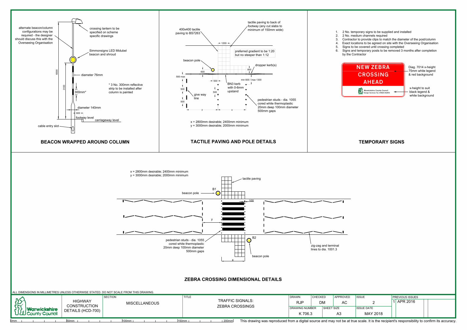
x
y
give way
line
dropper kerb(s)
BN3 kerb
with 0-6mm
upstand
min 600 / max 1300
500
500
600
400x400 tactile
paving to BS7263
preferred gradient to be 1:20
but no steeper than 1:12
tactile paving to back of
footway (any cut slabs to
minimum of 150mm wide)
TACTILE PAVING AND POLE DETAILS
1200
TEMPORARY SIGNS
1. 2 No. temporary signs to be supplied and installed
2. 2 No. medium channels required
3. Contractor to provide clips to match the diameter of the post/column
4. Exact locations to be agreed on site with the Overseeing Organisation
5. Signs to be covered until crossing completed
6. Signs and temporary posts to be removed 3 months after completion
by the Contractor
Diag. 7014 x-height
75mm white legend
& red background
x-height to suit
black legend &
white background
NEW ZEBRA
CROSSING
AHEAD
Warwickshire County Council
Design Services Tel: 01926 412810
6000
diameter 140mm
diameter 76mm
3100
cable entry slot
crossing lantern to be
specified on scheme
specific drawings
beacon pole
500
500 max
500
BEACON WRAPPED AROUND COLUMN
carriageway level
footway level
600
beacon pole
beacon pole
B1
B2
pedestrian studs - dia. 1055
cored white thermoplastic
20mm deep 100mm diameter
500mm gaps
tactile paving
ZEBRA CROSSING DIMENSIONAL DETAILS
300mm*
Simmonsigns LED Midubel
beacon and shroud
y
100
x
x = 2800mm desirable; 2400mm minimum
y = 3000mm desirable; 2000mm minimum
x = 2800mm desirable; 2400mm minimum
y = 3000mm desirable; 2000mm minimum
* 3 No. 300mm reflective
strip to be installed after
column is painted
800
alternate beacon/column
configurations may be
required - the designer
should discuss this with the
Overseeing Organisation
zig-zag and terminal
lines to dia. 1001.3
pedestrian studs - dia. 1055
cored white thermoplastic
20mm deep 100mm diameter
500mm gaps
HIGHWAY
CONSTRUCTION
DETAILS (HCD-700)
DRAWING NUMBER ISSUE DATE
DRAWN CHECKED
ALL DIMENSIONS IN MILLIMETRES UNLESS OTHERWISE STATED. DO NOT SCALE FROM THIS DRAWING.
SHEET SIZE
ISSUEPREVIOUS ISSUES
SECTION TITLE APPROVED
MISCELLANEOUS
TRAFFIC SIGNALS:
ZEBRA CROSSINGS
K 706.3
2
MAY 2018A3
RJP DM AC
1 APR 2016
This drawing was reproduced from a digital source and may not be at true scale. It is the recipient's responsibility to confirm its accuracy.
0mm 50mm 100mm 150mm 200mm


![· Caffè Latte [Hot/lce] ñ7x3yî- Café au Lait [Hot/lce] Cappuccino Espresso Hot Chocolate 650 1,000 650 700 700 700 700 700 700 700 700 700 To the guests who have some allergy](https://img.pdfslide.us/doc/110x75/5c674b4309d3f226588ba938/-caffe-latte-hotlce-n7x3yi-cafe-au-lait-hotlce-cappuccino-espresso.jpg)