Embed Size (px)
Citation preview
1
MANUAL OF CONTRACT DOCUMENTS FOR HIGHWAY WORKS VOLUME 2 NOTES FOR GUIDANCE ON THE SPECIFICATION FOR HIGHWAY WORKS
Amendment – February 2016
SERIES NG 700 ROAD PAVEMENTS – GENERALContentsClause Title Page
NG 700 (02/16) General 2
NG 701 (02/16) Pavement Construction 2
NG 702 (02/16) Horizontal Alignments, Surface Levels and Surface Regularity of Pavement Courses 2
#NG 706 (02/16) Excavation, Trimming and Reinstatement of Existing Surfaces 3
NG 710 (02/16) Testing for Constituent Materials in Recycled Aggregate and Recycled Concrete Aggregate 4
NG711 (02/16) Overbanding and Inlaid Crack Sealing Systems 4
NG 713 (02/16) Saw-cut and Seal Bituminous Overlays on Existing Jointed Concrete Pavements 5
NG 715 (02/16) Saw-cut, Crack and Seat Existing Jointed Reinforced Concrete Pavements 6
NG 716 (02/16) Cracking and Seating of Existing Jointed Unreinforced Concrete Pavements and Hydraulically Bound Mixture (HBM) Bases 7
NG 717 (02/16) Monitoring of Cracked and Seated Jointed Unreinforced Concrete Pavements and HBM Bases Using the Falling Weight Deflectometer (FWD) 8
NG 718 (02/16) Monitoring of Saw-cut, Cracked and Seated Jointed Reinforced Concrete Pavements Using the Falling Weight Deflectometer (FWD) 8
NG 719 (02/16) Back-analysis of Falling Weight Deflectometer (FWD) Measurements Made on Concrete Pavements Treated by Fractured Slab Techniques 9
#NG (02/16) Sample Contract Specific Appendices A1
NATIONAL ALTERATIONS OF THE OVERSEEING ORGANISATIONS OF SCOTLAND, WALES AND NORTHERN IRELANDContentsClause Title PageNorthern Ireland
NG 706NI (02/16) Excavation, Trimming and Reinstatement of Existing Surfaces N1F
Scotland
NG (02/16) Sample Contract Specific Appendices S1
# denotes a Clause or Sample Contract Specific Appendix which has a substitute National Clause or Sample Contract Specific Appendix for one or more of the Overseeing Organisations of Scotland, Wales or Northern Ireland.
2Amendment – February 2016
Volume 2 Series NG 700 Notes for Guidance on the Specification for Highway Works Road Pavements – General
ROAD PAVEMENTS – GENERAL
NG 700 (02/16) General
1 (02/16) Advice on the design, construction and maintenance of roads is published in The Design Manual for Roads and Bridges (DMRB) Volume 7.
NG 701 (02/16) Pavement Construction
1 (02/16) Unless otherwise agreed by the Overseeing Organisation all types of pavement construction (flexible, and rigid; as defined in Standard HD 26 Pavement Design (DMRB 7.2.3)) should be permitted as alternatives for the main carriageways on new works and reconstruction work and work to side roads on trunk road contracts. Also the alternative component layers and layer materials within these 2 types should wherever possible be permitted.
Where a restriction of pavement types and/or their component layers/materials is considered necessary on the main carriageway in new works and reconstruction work and work to side roads on trunk road contracts, details and justification are to be submitted to the Overseeing Organisation for approval.
2 (02/16) The series of schedules presented in contract specific Appendix 7/1 should be completed and referenced to the drawings.
3 (02/16) Where the subgrade CBR value is estimated to be of a value requiring capping for one type of pavement (eg. rigid) but not for others permitted for the same length of carriageway this should be clearly shown on Schedule 3 in contract specific Appendix 7/l and allowed for in contract specific Appendix 6/7.
NG 702 (02/16) Horizontal Alignments, Surface Levels and Surface Regularity of Pavement Courses
1 (02/16) All levels of pavement courses are related to the specified level of the final road surface. Tolerances and limits in levels and irregularity are given in Tables 7/1 and 7/2 respectively. These should be strictly enforced to maintain a good ride and constant thickness of material. As they are based on the capabilities of most pavers to lay to a level they do not allow for any intentional reduction of the pavement thickness. For Slurry Surfacing referred to in Clause 918, the surface irregularities should meet the appropriate requirements of Tables NG 9/4 to NG 9/7.
2 (02/16) Surface levels of different pavement courses should be measured at points on a grid described in contract specific Appendix 7/1 in order to be able to determine the thickness of each course from the successive measurement of levels at the grid points. The spacing of the grid should normally be 10 m longitudinally and 2 m transversely. Where a greater degree of level control is required, eg at junctions of the carriageway with side roads, on slip roads and roundabouts, but not joints in the carriageway, the grid points should be at some lesser spacing. Measurement of surface levels at points on a grid does not mean that the surface can be outside the permitted tolerances at other points between the grid.
3 (02/16) The tolerances on surface levels of surface courses, and concrete slabs are set in order to provide as good a ride as possible and avoid undulations of an individual or cyclic nature, which are of a wavelength outside the range detectable by the rolling straight-edge or equivalent apparatus. If, however, through a fault in the paving plant the whole surface as laid is consistently high over long lengths, it would be unnecessary to impose the limits of the true surface level tolerances, provided:
(i) Clearances under bridges are adequate, and allow for overlays.
(ii) The drainage of the carriageway is not impaired.
(iii) All tolerances except those on the final road surface design level comply with the specification.
(iv) The area affected is of such length as to provide an acceptable ride.

Amendment – February 2016 3
Volume 2 Series NG 700 Notes for Guidance on the Specification for Highway Works Road Pavements – General
4 (02/16) The limits for surface regularity of subbases under concrete pavement surface slabs is necessarily less when the slabs are laid in a single layer and only compacted by surface compacting beams. With a standard surcharge and a fixed degree of compaction with such equipment, upward variations in the subbase can be reflected in the surface when the concrete is fully compacted, whereas downward variations will result in lack of compaction locally. These tighter tolerances do not apply when internal vibration is used.
5 (02/16) Two categories of road are given in Table 7/2, and for each different section of road the category must be stated in contract specific Appendix 7/1. The Overseeing Organisation will decide the category on the quality and quantity of traffic, on the road layout and potential speeds of traffic. Category B is generally for low speed (under 50 km/h) roads. Table 7/2 does not apply to materials laid in accordance with Clause 918.
6 (02/16) The surface should be thoroughly swept to remove extraneous matter before measurements are taken. All such measurements should be taken early, and any deficiencies in the pavement should be reported as soon as possible to allow the Contractor sufficient time to complete all remedial work and to allow for concrete to cure before opening the road to traffic. The rolling straight-edge should be used at about 2 km/hour. Some coarse textures can lead to incorrect readings if the surface is traversed too quickly. Areas shown not to comply with the specification should be rectified as soon as possible and checked by a 3 m straight-edge or, for longer lengths, by the rolling straight edge or equivalent apparatus.
7 (02/16) Traces from profilometers are useful in picking out particular areas for remedial work from the whole stretch shown not to comply with the specification by the rolling straight-edge or equivalent apparatus.
8 (02/16) For rectifying concrete slabs use of a bump cutter with a long wheel base is essential to produce an even plane without local overcutting. Grinding down either side of depressions may improve the riding quality, if they are small. Deeper depressions should normally be rectified by cutting out and refilling.
#NG 706 (02/16) Excavation, Trimming and Reinstatement of Existing Surfaces
1 (02/16) Clause 706 describes a method of excavation and reinstatement of existing paved and unpaved surfaces:
(i) Where the Contractor is required to break into paved areas for the installation of utilities.
(ii) Where the Contractor unavoidably has to break into work which he has carried out as part of the works.
(iii) Where he is required to break into paved areas existing prior to the works being constructed.
(iv) Where pavements are constructed to abut or join into existing pavements.
2 (02/16) Instructions on the installation of utilities in roads designed to carry 125 msa or less are given in a Code of Practice entitled ‘Specification for the Reinstatement of Openings in Highways’ by the Highway Authorities and Utilities Committee. This Code of Practice was produced as a result of certain provisions of the New Roads and Street Works Act 1991.
3 (02/16) As much information as possible should be provided in contract specific Appendix 7/2 and on the drawings for 1(ii) and (iii) above, especially to show the areas and depth of pavement required to match levels between new and existing construction. The intention is to ensure that at least a new surface course should be provided over the minimum area of existing pavement as will avoid feathering below the minimum thickness of the layer, after preparation of the existing surface by scarifying and planing. Where existing and new concrete pavements abut or join into each other it is normal practice to use a bituminous pavement between the two sections, details of which should be given in contract specific Appendix 7/2.
4 (02/16) Paved areas already constructed as part of the permanent works should only be excavated when it is necessary to carry out the permanent works or where no other practical means of completing the permanent works can be devised.
5 (02/16) Advice and methods of reinstating pavements are given in the ‘Design Manual for Roads and Bridges. Volume 7 : Pavement Design and Maintenance : Section 4 : Pavement Maintenance Methods : Parts 1 and 2 (DMRB 7.4.1 and 7.4.2)’.

4Amendment – February 2016
Volume 2 Series NG 700 Notes for Guidance on the Specification for Highway Works Road Pavements – General
Advice and methods of reinstating concrete pavements are given in the ‘Concrete Pavement Maintenance Manual’ published by the Concrete Society.
NG 710 (02/16) Testing for Constituent Materials in Recycled Aggregate and Recycled Concrete Aggregate
1 (02/16) ‘Quality Protocol for the production of aggregates from inert waste’ and the ‘Producers’ compliance checklist’ published by Waste and Resources Action Programme are available from WRAP, The Old Academy, 21 Horse Fair, Banbury OX16 0AH. The documents are also available on the WRAP website, http://www.wrap.org.uk./construction
(02/16) Limitations of the Test Method
2 (02/16) This test method specifies a basic procedure for the examination of recycled aggregate and recycled concrete aggregate for the purpose of identifying and quantifying constituent components. The test is designed to give a reliable go/no go decision rather than to provide a low relative error estimate of constituent contents. The operating characteristics of the test should ensure that materials well within the specification have little chance of rejection whereas materials well outside the specification have little chance of acceptance.
NG711 (02/16) Overbanding and Inlaid Crack Sealing Systems
1 (02/16) A crack sealing system is defined in the BBA HAPAS ‘Guidelines Document for the Assessment and Certification of Crack Sealing Systems for Highways’ as a method of repairing cracks in non-porous (ie. not porous asphalt) bituminous highway surfaces with macrotexture depths not exceeding 2 mm (volumetric patch technique), or in concrete highway surfaces. Where practicable the colour of system specified should be similar to the adjacent surface.
2 (02/16) Crack sealing systems are categorised as:
(i) Simple Overbanding Systems for repairing crack widths up to 5 mm.
(ii) Fill and Overbanding Systems for repairing crack widths between 5 mm and 20 mm.
(iii) Inlaid Sealing Systems for repairing crack widths in excess of 20 mm, or adjacent multiple cracks.
3 (02/16) Inlaid sealing systems are installed by routing or planing out the crack to form a recess and applying the product flush with the adjacent highway surface. They may be used in conjunction with certified overbanding systems along the joints. Inlaid systems used to seal isolated cracks should not be wider than 250 mm, however when sealing multiple cracks this width may be exceeded.
4 (02/16) Inlaid crack sealing systems are classified by the BBA HAPAS scheme as either Grade F (Flexible) or Grade H (High Modulus). Grade F offers more flexibility but in consequence has a slightly reduced resistance to deformation, ie. rut resistance. Grade H is less flexible but has a high resistance to deformation. Which grade to specify is a matter of judgement. Where significant crack movement is anticipated, for example in cracks in overlays to jointed concrete carriageways, Grade F may be more appropriate. Where cracks do not penetrate through the pavement structure and significant movement is unlikely to occur, or for small patches in the wheel-tracks, then Grade H may be more appropriate.
(02/16) Expected Minimum Life
5 (02/16) Overbanding systems and Inlaid crack sealing systems are used to seal and repair cracks both longitudinally and transverse to the carriageway. Where pavements are structurally sound and cracking is confined to the surfacing layer or layers, and these remain bonded to the base, then the minimum expected life for overbanding systems predicted in BBA HAPAS Certificates will be 3 or 5 years, dependent on test results, and for inlaid systems 5 years. However, where cracks have penetrated substantially through the pavement depth due to structural failure resulting in significant movement under traffic, no expectation of life can be reliably predicted.

Amendment – February 2016 5
Volume 2 Series NG 700 Notes for Guidance on the Specification for Highway Works Road Pavements – General
6 (02/16) The most severe wear from trafficking (primarily by heavy goods vehicles) occurs within the wheeltrack zones, approximately between 0.5 m and 1.1 m, and between 2.55 m and 3.15 m from the centre of the nearside lane markings for each traffic lane. In the wheeltrack zones, the expected minimum life of crack sealing systems is unlikely to be exceeded. Conversely for cracks outside the wheeltrack zones, provided the pavement surface is otherwise sound, the expected minimum lives in terms of skidding and deformation resistance are likely to be exceeded. The most onerous conditions occur during summer months on heavily trafficked south facing carriageways with significant gradients in cuttings and on the surface of pavements carried by elevated structures, when surface temperatures can approach or exceed 50°C. Should surface temperatures exceed this figure for periods in an exceptional summer, then the expected minimum lives of products installed in the wheeltrack zones may not be attained.
(02/16) Narrow Isolated Cracks
7 (02/16) Narrow isolated cracks less than 20 mm in width, in surfacings unlikely to ravel away from the crack, may be sealed without overbanding or inlay using a hot applied joint sealant Type N2 to BS EN 14188-1 in accordance with the recommendations of DMRB (7.4.1).
NG 713 (02/16) Saw-cut and Seal Bituminous Overlays on Existing Jointed Concrete Pavements
1 (02/16) Generally, where there is an existing mid-bay crack in a reinforced concrete slab, no surface treatment is required.
2 (02/16) Where there is existing bituminous surfacing greater than 40 mm thick, it may be appropriate to only remove the surfacing in a transverse strip symmetrically about a joint and replace with bituminous inlay. This is then saw-cut and sealed to sub-Clause 713.4. Otherwise, all the existing bituminous surfacing will require to be planed off, as specified in sub-Clause 713.2.
3 (02/16) When the total thickness of bituminous overlay to the existing concrete pavement is designed to be 40 mm or less, saw-cut and seal techniques to Clause 713 should not be used. In such cases, reflection cracks should be routed out and sealed with hot-applied sealant to comply with BS EN 14188-1. Saw-cut and seal techniques to Clause 713 should not be used when the total thickness of bituminous overlay is designed to be 180 mm or greater.
4 (02/16) As part of the design assessment, and before any laying of bituminous surfacing, attention needs to be paid to the consequences of previous part-bay repairs, particularly in situations where there is lack of a continuous or co-linear transverse joint.
5 (02/16) Jointed reinforced concrete pavements with bays exceeding 6 m in length may first be prepared by ‘Saw-cut, crack and seat’ to Clause 715, prior to bituminous overlay. However, this may depend on the condition of a slab and its support.
6 (02/16) Bituminous overlays may be selected from the following Clauses:
Regulating course Binder course Surface course*907 and either 903 or 906 906 911**or 929 (DBM and HDM only) 929 942or 906 906 943or 937 937 9xx* surfacing shall also meet appropriate noise requirements** lightly trafficked roads onlyHigh modulus materials to Clause 929 should not be used.
7 (02/16) When monitoring the co-linearity of existing concrete joints and new saw-cut grooves in connection with sub-Clauses 713.7 and 713.9, it may be helpful to adopt special investigatory techniques, for example, radar. See DMRB (7.3.2). This would be in addition to the careful application of survey control methods required under the Clause.
6Amendment – February 2016
Volume 2 Series NG 700 Notes for Guidance on the Specification for Highway Works Road Pavements – General
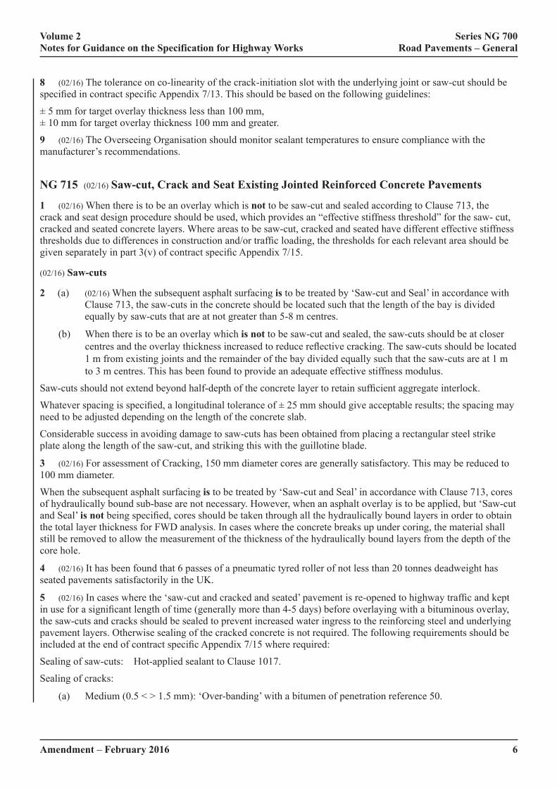
8 (02/16) The tolerance on co-linearity of the crack-initiation slot with the underlying joint or saw-cut should be specified in contract specific Appendix 7/13. This should be based on the following guidelines:
± 5 mm for target overlay thickness less than 100 mm, ± 10 mm for target overlay thickness 100 mm and greater.
9 (02/16) The Overseeing Organisation should monitor sealant temperatures to ensure compliance with the manufacturer’s recommendations.
NG 715 (02/16) Saw-cut, Crack and Seat Existing Jointed Reinforced Concrete Pavements
1 (02/16) When there is to be an overlay which is not to be saw-cut and sealed according to Clause 713, the crack and seat design procedure should be used, which provides an “effective stiffness threshold” for the saw- cut, cracked and seated concrete layers. Where areas to be saw-cut, cracked and seated have different effective stiffness thresholds due to differences in construction and/or traffic loading, the thresholds for each relevant area should be given separately in part 3(v) of contract specific Appendix 7/15.
(02/16) Saw-cuts
2 (a) (02/16) When the subsequent asphalt surfacing is to be treated by ‘Saw-cut and Seal’ in accordance with Clause 713, the saw-cuts in the concrete should be located such that the length of the bay is divided equally by saw-cuts that are at not greater than 5-8 m centres.
(b) When there is to be an overlay which is not to be saw-cut and sealed, the saw-cuts should be at closer centres and the overlay thickness increased to reduce reflective cracking. The saw-cuts should be located 1 m from existing joints and the remainder of the bay divided equally such that the saw-cuts are at 1 m to 3 m centres. This has been found to provide an adequate effective stiffness modulus.
Saw-cuts should not extend beyond half-depth of the concrete layer to retain sufficient aggregate interlock.
Whatever spacing is specified, a longitudinal tolerance of ± 25 mm should give acceptable results; the spacing may need to be adjusted depending on the length of the concrete slab.
Considerable success in avoiding damage to saw-cuts has been obtained from placing a rectangular steel strike plate along the length of the saw-cut, and striking this with the guillotine blade.
3 (02/16) For assessment of Cracking, 150 mm diameter cores are generally satisfactory. This may be reduced to 100 mm diameter.
When the subsequent asphalt surfacing is to be treated by ‘Saw-cut and Seal’ in accordance with Clause 713, cores of hydraulically bound sub-base are not necessary. However, when an asphalt overlay is to be applied, but ‘Saw-cut and Seal’ is not being specified, cores should be taken through all the hydraulically bound layers in order to obtain the total layer thickness for FWD analysis. In cases where the concrete breaks up under coring, the material shall still be removed to allow the measurement of the thickness of the hydraulically bound layers from the depth of the core hole.
4 (02/16) It has been found that 6 passes of a pneumatic tyred roller of not less than 20 tonnes deadweight has seated pavements satisfactorily in the UK.
5 (02/16) In cases where the ‘saw-cut and cracked and seated’ pavement is re-opened to highway traffic and kept in use for a significant length of time (generally more than 4-5 days) before overlaying with a bituminous overlay, the saw-cuts and cracks should be sealed to prevent increased water ingress to the reinforcing steel and underlying pavement layers. Otherwise sealing of the cracked concrete is not required. The following requirements should be included at the end of contract specific Appendix 7/15 where required:
Sealing of saw-cuts: Hot-applied sealant to Clause 1017.
Sealing of cracks:
(a) Medium (0.5 < > 1.5 mm): ‘Over-banding’ with a bitumen of penetration reference 50.

Amendment – February 2016 7
Volume 2 Series NG 700 Notes for Guidance on the Specification for Highway Works Road Pavements – General
(b) Wide (>1.5 mm): Chase out cracks and seal with 15D x 10W D3406 sealant.
6 (02/16) The location of the trial should be representative of the main body of the work under this Clause, for example, it should be neither at the thickest part of the reinforced concrete pavement layer nor at parts which are showing atypical deterioration, nor over the worst formation.
7 (02/16) If it is known that there are differing pavement constructions within the scheme, more than one trial will be required and should be specified in contract specific Appendix 7/15.
8 (02/16) In contract specific Appendix 7/15, the following section should be completed by the compiler as noted:
FWD Testing & Measurements:
(i) When the subsequent asphalt surfacing is to be treated by ‘Saw-cut and Seal’ in accordance with Clause 713, FWD testing is not necessary.
(ii) When the subsequent asphalt surfacing is not to be treated by ‘Saw-cut and Seal’ in accordance with Clause 713, FWD testing of effective stiffness only is necessary.
(iii) FWD testing of joint load transfer efficiency (LTE) may be performed for information purposes only; there are currently no criteria for acceptable levels of LTE after Saw-cut, Crack and Seat.
(02/16) Tack Coat and Bond Coat
9 (02/16) The treated concrete surface should be tack or bond coated in accordance with contract specific Appendix 7/4 prior to overlaying.
NG 716 (02/16) Cracking and Seating of Existing Jointed Unreinforced Concrete Pavements and Hydraulically Bound Mixture (HBM) Bases
1 (02/16) Within Clause 716, the term “hydraulically bound layer” refers to both jointed unreinforced concrete and HBM bases. The crack and seat design procedure provides an “effective stiffness threshold” for the cracked and seated hydraulically bound layers. Where areas to be cracked and seated have different effective stiffness thresholds due to differences in construction and/or traffic loading, the thresholds for each relevant area should be given separately in part 3(iii) of contract specific Appendix 7/16.
2 (02/16) The spacing of transverse cracks for the main trial should be specified as two or three alternatives in item (5)(i) of contract specific Appendix 7/16, all of which should be trialled in accordance with sub-Clause 716.18(iii). From previous trials, the spacing of cracks should be between 0.75 m and 2 m. For jointed pavement quality concrete, the spacing alternatives in the main trial should be chosen such that the crack spacing divides exactly into the bay length.
3 (02/16) A tolerance on the spacing of transverse cracks of ± 5% is achievable. It may need to be based on average values over a bay length or a 5 m run for HBM bases.
4 (02/16) Where the pavement construction consists of more than one layer of hydraulically bound material, the cores should be taken through all the hydraulically bound layers in order to obtain the total layer thickness for FWD analysis. In cases where the concrete breaks up under coring, the material shall still be removed in order to allow the measurement of the thickness of the hydraulically bound layers from the depth of the core hole.
5 (02/16) In cases where the cracked and seated pavement is to be re-opened to highway traffic and is intended to be kept in use for a significant length of time (generally more than 4-5 days, or if prolonged poor weather is anticipated) before overlaying with an asphalt overlay, the cracks should be sealed as follows. Otherwise sealing of the cracked concrete is not required. The following requirements should be included at the end of contract specific Appendix 7/16:
Sealing of cracks:
(a) Medium (0.5 < > 1.5 mm): ‘Over-banding’ with a bitumen of penetration reference 50.
(b) Wide(>1.5 mm): Chase out cracks and seal with 15D x 10W D3406 sealant.

8Amendment – February 2016
Volume 2 Series NG 700 Notes for Guidance on the Specification for Highway Works Road Pavements – General
6 (02/16) The location of the trial should be representative of the main body of the work under this Clause, for example, it should be neither at the thickest part of the hydraulically bound layer nor at the part which is cracked already, nor over the worst formation.
7 (02/16) If it is known that there are differing pavement constructions within the scheme, more than one trial will be required and should be specified in contract specific Appendix 7/16.
(02/16) Tack Coat and Bond Coat
8 (02/16) The treated surface should be tack or bond coated in accordance with contract specific Appendix 7/4 prior to overlaying.
NG 717 (02/16) Monitoring of Cracked and Seated Jointed Unreinforced Concrete Pavements and HBM Bases using the Falling Weight Deflectometer (FWD)
1 (02/16) In principle, the FWD generates a load pulse by dropping a mass onto a spring system. The mass and drop height can be adjusted to achieve the desired impact loading. Peak vertical deflections are measured at the centre of the loading plate and at several radial positions by a series of geophones. These deflections and the peak impact load are stored electronically. FWDs vary in detail depending on manufacturer. Ferne (1990) has reported on comparative trials of FWD systems in use in the UK and found good agreement in machine performance. Testing apparatus that is to be used on Highways England’s network is required to have a valid certificate. In order to obtain the appropriate certification Highways England, through a third party, arranges for correlation testing to undertaken.
2 (02/16) The Main Trial, as specified in Clause 716, is designed to (i) enable the Contractor to demonstrate that their proposed plant, equipment and method for the cracking and seating of the existing hydraulically bound layer or layers is capable of producing the required type and pattern of cracks, and (ii) allow the Overseeing Organisation to select the appropriate spacing of the transverse cracks for use in the main works. For cracking and seating of jointed, unreinforced, concrete pavements, the Main Trial allows the Overseeing Organisation to select the location where FWD measurements shall be made on individual bays in the monitoring of the Main Works production cracking.
3 (02/16) Stage 1 of the Main Trial permits the Contractor to set up his cracking machine. Stage 2 and subsequent Stages enable the Overseeing Organisation to evaluate the effects of different crack spacings and impact loads on the crack pattern and on the effective stiffness modulus of the cracked concrete.
NG 718 (02/16) Monitoring of Saw-cut, Cracked and Seated Jointed Reinforced Concrete Pavements using the Falling Weight Deflectometer (FWD)
1 (02/16) In principle, the FWD generates a load pulse by dropping a mass onto a spring system. The mass and drop height can be adjusted to achieve the desired impact loading. Peak vertical deflections are measured at the centre of the loading plate and at several radial positions by a series of geophones. These deflections and the peak impact load are stored electronically. FWDs vary in detail depending on manufacturer. Ferne (1990) has reported on comparative trials of FWD systems in use in the UK and found good agreement in machine performance.
2 (02/16) The Main Trial, as specified in Clause 715, is designed to (i) enable the Contractor to demonstrate that their proposed plant, equipment and method for the saw-cut, cracking and seating of the existing hydraulically bound layer or layers is capable of producing the required type and pattern of cracks, and (ii) allow the Overseeing Organisation to select the appropriate spacing of the transverse saw-cuts for use in the main works.
3 (02/16) Stage 1 of the Main Trial permits the Contractor to set up his cracking machine. Stage 2 and subsequent Stages enable the Overseeing Organisation to evaluate the effects of different saw-cut spacings and impact loads on the crack pattern and on the effective stiffness modulus of the saw-cut, cracked and seated concrete.

Amendment – February 2016 9
Volume 2 Series NG 700 Notes for Guidance on the Specification for Highway Works Road Pavements – General
NG 719 (02/16) Back-analysis of Falling Weight Deflectometer (FWD) measurements made on Concrete Pavements treated by Fractured Slab Techniques.
1 (02/16) This Clause sets out the procedure by which the Contractor shall calculate the effective stiffness moduli of the fractured concrete layer (or layers) and the underlying foundation from deflection data produced by the Falling Weight Deflectometer (FWD) on pavements treated by “Fractured Slab” techniques. “Fractured Slab” techniques refer to the following:
(i) Crack and seat of jointed unreinforced concrete pavements and HBM bases in accordance with Clause 716.
(ii) Saw-cut and crack and seat of jointed reinforced concrete pavements in accordance with Clause 715.
2 (02/16) The FWD is primarily used to validate whether the effective stiffness modulus of the fractured hydraulically bound layer or layers exceeds the threshold value determined from the structural design calculations and given in contract specific Appendix 7/16 for crack and seat and contract specific Appendix 7/15 for saw-cut, crack and seat. The method of analysis and the required input parameters are specified together with the form of the output to be provided to the Overseeing Organisation for assessment and interpretation.
3 (02/16) Fractured Slab techniques are used to inhibit reflection cracking in subsequent asphalt overlays. However, the techniques also have a weakening effect on the concrete. It is therefore highly important that the overlay thickness to be applied to the treated pavement can carry the anticipated future traffic loading. The current approved Highways England methodology for overlay design on pavements treated by Fractured Slab techniques therefore calculates a “threshold modulus value” for the fractured concrete. It is important that the effective stiffness modulus of the fractured concrete meets or exceeds this value in order for the pavement to achieve its design life. FWD testing is used to ensure that the design threshold stiffness is achieved during construction by assessing the stiffness of the fractured concrete using the technique of back-analysis.
4 (02/16) FWD deflections can be used to back-calculate a stiffness modulus with reasonable accuracy. However, back-analysis of FWD deflection measurements on fractured concrete produces an ‘effective’ stiffness modulus because the calculations assume that the deflection bowl is measured on a uniform structure. While it is appreciated that fractured concrete is not, in practice, a homogeneous layer, research findings indicate that this back-analysis model can produce consistent results provided that the cracks are fine and maintain good aggregate interlock.
The effective stiffness modulus of the fractured concrete, together with that of its underlying foundation, is calculated from the back-analysis of FWD deflection bowl measurements by means of a computer program. Highways England has produced such a suitable program, MODULUS-HA, and made it, and its accompanying User Guide, freely available. It should be noted that the use of alternative software is permitted however the output values from any alternative software used must be proven to match those from MODULUS-HA.
The latest versions of MODULUS-HA and of the MODULUS-HA User’s Guide can be obtained by contacting Highways England.
5 (02/16) Accurate measurement of layer thickness is essential for meaningful back-analysis. An under-estimate of as little as fifteen percent in thickness can result in an over estimate of over fifty percent in bound layer moduli values, enough to give the impression of good integrity of a poor layer.
6 (02/16) For pavement construction with more than one hydraulically bound layer, all the concrete layers, including an HBM sub-base if present under jointed concrete, shall be modelled as one layer with a total thickness equal to the combined thickness of the individual layers. The back-analysed results are estimates of the stiffnesses of the single or combined hydraulically bound layer and of the combined unbound sub-base and subgrade materials present.
As the back-analysis of concrete pavements treated by crack and seat utilises a simple two-layer model, only the thickness of the bound layers is required as the unbound layers are modelled as a single layer of infinite depth. Sufficient cores should be taken as part of the assessment of the cracking operation to provide a reliable record of layer thickness data for the back-analysis. The rate of coring required by Clause 716 results in samples being taken approximately every 75 m per traffic lane. Supplementary layer thicknesses derived from existing Ground Penetrating Radar surveys may also be used to supplement the core results to improve the accuracy of the thickness

Amendment – February 2016
Volume 2 Series NG 700 Notes for Guidance on the Specification for Highway Works Road Pavements – General
10F
calculations, and are particularly useful where an HBM sub-base is present due to the variability in thickness often found with this material.
7 (02/16) The basic processing methodology used to produce back-analysed effective stiffness moduli is the same for both trial area and main works monitoring. The data format used by MODULUS-HA in its back-analysis routines takes the form of an “.OUT” text file. The structure of the data within the .OUT text files is given in Appendix E of the MODULUS-HA User’s Guide.
8 (02/16) Values of RMS and AMD are required in order to enable the Overseeing Organisation to assess the “goodness of fit” of the back-analysed deflection data and are automatically produced by the MODULUS-HA back-analysis procedure. These parameters are described more fully in HD 29 within Volume 7 of the Design Manual for Roads and Bridges. At this stage the information is for information only.
9 (02/16) A Main Trial is designed to enable the Contractor to demonstrate that his proposed plant, equipment and method for the fracturing of the existing hydraulically bound layer or layers is capable of producing the required type and pattern of cracks. It also permits the Overseeing Organisation to select the appropriate spacing of the transverse cracks for use in the main works. For cracking and seating of jointed, unreinforced concrete pavements, it also permits the Overseeing Organisation to select the location where FWD measurements shall be made on individual bays in the main works.
10 (02/16) The Overseeing Organisation is responsible for interpreting the back-analysed FWD data arising from monitoring of the Main Trial and Main Production Works to validate whether the effective stiffness modulus of the fractured concrete satisfies the required structural design criteria.
11 (02/16) A Production Cracking Reassessment Trial is required when, during Main Production Works, the crack patterns and characteristics determined from the main trial are not maintained for the length of 4 bays in jointed unreinforced concrete pavements or for a distance of 20 m in HBM bases and jointed reinforced concrete pavements. The Reassessment Trial is performed in accordance with Clause 716 for crack and seat or Clause 715 for saw-cut, crack and seat.
12 (02/16) The period of time to be specified in section 11 of contract specific Appendix 7/19 to be allowed by the Contractor should be sufficient to allow the Overseeing Organisation to complete his assessment of the back-analysed results and determine the nature and extent of any required remedial actions, including, if necessary, a re-design of the structural requirements of the pavement. The back-analysed results may be submitted by the Contractor at any time of day.

Amendment – February 2016 A1
Volume 2 Series NG 700 Notes for Guidance on the Specification for Highway Works Road Pavements – General
(02/16) #NG SAMPLE CONTRACT SPECIFIC APPENDIX 7/1: PERMITTED PAVEMENT OPTIONS1 (02/16) PERMITTED PAVEMENT OPTIONS – SCHEDULE 1
[Note to compiler: Complete Schedule 1. See NG 701.2].
Schedule 1: Permitted Pavement OptionsDrawing Ref. Area General
RequirementsPermitted Pavement Option
Area A Schedule 2A A1 A2 A3 etc.Area B Schedule 2B B1 B2 B3 etc.Area C Schedule 2C C1 C2 C3 etc.etc. etc. etc. etc. etc. etc.
[Note to compiler: The above schedule should include all options for flexible, flexible composite, rigid and rigid composite construction for all areas, with each permitted pavement option given a unique reference number, for example, A1. An appropriate drawing reference should be inserted for each area.]
2 (02/16) GENERAL REQUIREMENTS – SCHEDULE 2
[Note to compiler: Complete Schedule 2. See NG 701.2 Where necessary, a separate General Requirements Schedule should be completed for each of the Areas identified in Schedule 1].
Schedule 2: General Requirements – Area [……]Grid for checking surface levels of pavement courses [702.4]: Longitudinal dimension:
Transverse dimension:Surface regularity [702.5, Table 7/2] Category of Road:Interval for measurement of longitudinal regularity [702.7]:Interval for measurement of transverse regularity [702.8]:

A2Amendment – February 2016
Volume 2 Series NG 700 Notes for Guidance on the Specification for Highway Works Road Pavements – General
3 (02/16) PERMITTED CONSTRUCTION MATERIALS – SCHEDULE 3
[Note to compiler: Complete Schedule 3. See NG 701.2. A separate Permitted Construction Materials Schedule should be completed for each of the Permitted Pavement Options identified in Schedule 1.]
Schedule 3: Permitted Construction MaterialsPavement Option [eg A1] Pavement Option [eg A2]
Pavement Layer Material Ref. Thickness (mm) Material Ref. Thickness (mm)Surface Treatment STA1**Surface Course SCA1** SCA2**Binder Course BCA1** BCA2**Base BA1**Upper base UBA2**Lower base LBA2**Subbase SBA1** SBA2**[Other – eg regulating]
RA1**
Total ThicknessCapping is not required/is required* as described in contract specific Appendix 6/7. [*Compiler to indicate as appropriate]
[** Compiler’s unique reference for insertion in Schedule 5]

Amendment – February 2016 A3
Volume 2 Series NG 700 Notes for Guidance on the Specification for Highway Works Road Pavements – General
4 (02/16) GENERAL REQUIREMENTS FOR CONSTRUCTION MATERIALS – SCHEDULE 4
[Note to compiler: Complete Schedule 4. See NG 701.2.].
Schedule 4: General Requirements for Construction MaterialsClause Requirement801.2 Limiting distance for deposition of unbound mixtures referred to in sub-Clause 801.2801.3 Limiting distance for deposition of unbound mixtures referred to in sub-Clause 801.3801.7 Whether any material shall not comply with sub-Clause 801.7.802.4 Whether unbound materials up to 225 mm compacted thickness can be spread in more than one
layer.802.14 Thickness of compacted layer.810.6 Whether the coefficient of linear expansion of the mixture is to be determined, using the test
method specified in Clause 871.818.1 Whether induced transverse cracks are required; and the specified spacing of induced transverse
cracks.818.3 Whether induced longitudinal cracks are required; and the specified location of induced
longitudinal cracks.820.2 When an existing pavement layer is used to produce HBM, whether the recycled aggregate or
recycled concrete aggregate is to be tested to confirm compliance with sub-Clause 820.1.901.6 Requirements for resistance to fragmentation (hardness) if different from the requirements of sub-
Clause 901.6.901.7 Requirements for resistance to freezing and thawing (durability) if different from the requirements
of sub-Clause 901.7.901.8 Requirements for cleanness if different from the requirements of sub-Clause 901.8.902.2 Requirements for reclaimed asphalt if different from the requirements of sub-clause 902.2.903.21 Requirements for positioning of longitudinal joints if different from the requirements of 903.21.903.22 Requirements for treating the faces of cold upstanding edges if different from the requirements of
903.22.903.23 Requirements for assessment of compaction at joints in binder courses and bases if different from
the requirements of 903.23.903.24 Whether sealant shall be applied to the top surface of all base and binder course joints.903.25 Whether sealant shall be applied to any freestanding edge of the finished pavement.903.27 Requirements for PSV of temporary running surface if different from sub-Clause 903.27. [Compiler
to list pavement materials applicable].925.2 Whether a demonstration or approval trial is required. [Compiler to list pavement materials
applicable].1001.2 Requirements for concrete conformity if different from sub-Clause 1001.2.1004.7 Testing requirements for concrete cubes.1028 Requirements for trial lengths.1033.10 Permission for butt welding.

A4Amendment – February 2016
Volume 2 Series NG 700 Notes for Guidance on the Specification for Highway Works Road Pavements – General
5 (02/16) REQUIREMENTS FOR CONSTRUCTION MATERIALS – SCHEDULE 5
[Note to compiler: Schedule 5 should be completed for every permitted construction material identified in Schedule 3.]
Schedule 5: Requirements for Construction Materials Material Ref.
Clause Description Requirement
803 Type 1 unbound mixture Mixtures containing crushed gravel coarse aggregate: – permitted [803.1]: – minimum CBR [803.8]: – trafficking trial [803.8]:
804 Type 2 unbound mixture Minimum CBR: – required [804.6]: – minimum value [804.6]:
Mixtures containing more than 50% asphalt arisings: – permitted [804.1]: – trafficking trial [804.11]
807 Type 4 (asphalt arisings) unbound mixture
Trafficking trial: – required [807.9]
820 Aggregates for HBM Rock coarse aggregates [820.2]821 Cement bound granular
mixtures A (CBGM A)Laboratory mechanical performance category: C 3/4, C 5/6, C 8/10; T1, T2, T3 [821.5 and Table NG 8/2]
822 Cement bound granular mixtures B (CBGM B)
Aggregate requirements: LA50 or LA60 [822.2, Table 8/12] Laboratory mechanical performance category: C 8/10, C 12/15, C 16/20, C 20/25; T3, T4, T5 [822.5 and Table NG 8/2]
823 Cement bound granular mixtures C (CBGM C)
Laboratory mechanical performance category: C 8/10, C12/15, C 16/20, C20/25; T3, T4, T5 [823.6 and Table NG 8/2]
830 Fly ash bound mixture 1 (FABM 1) and Hydraulic road binder bound mixture 1 (HRBBM 1)
Aggregate requirements: C90/3, or C50/30, LA50, or LA60 [830.2, Table 8/12] Laboratory mechanical performance category: C 6/8, C 9/12, C 12/16, C 15/20, C 18/24; T2, T3, T4 [830.5 and Table NG 8/2]
831 Slag bound mixture B2 (SBM B2), Fly ash bound mixture 2 (FABM 2) and Hydraulic road binder bound mixture 2 (HRBBM 2)
Aggregate requirements: C90/3, or C50/30 [831.2, Table 8/12] Laboratory mechanical performance category: C 6/8, C 9/12, C 12/16, C 15/20, C 18/24; T2, T3, T4 [831.7 and Table NG 8/2]
832 Slag bound mixture B3 (SBM B3), Fly ash bound mixture 3 (FABM 3) and Hydraulic road binder bound mixture 3 (HRBBM 3)
Laboratory mechanical performance category: C 3/4, C 6/8, C 9/12, C 12/16, T1, T2, T3 [832.5 and Table NG 8/2]
834 Fly ash bound mixture 5 (FABM 5)
Laboratory mechanical performance category: C 3/4, C 6/8; T1, T2 [834.4]

A5
Volume 2 Series NG 700 Notes for Guidance on the Specification for Highway Works Road Pavements – General
Amendment – May 2018
Schedule 5: Requirements for Construction Materials (continued)Material Ref.
Clause Description Requirement
835 Slag Bound Mixtures B1-1, B1-2, B1-3 & B1-4 (SBM B1)
Aggregate requirements: C90/3, or C50/30, [835.2, Table 8/12] Laboratory mechanical performance category: C 6/8, C 9/12, C 12/16, C 15/20, C 18/24; T2, T3, T4 [835.5 and Table NG 8/2]
840 Soil treated by cement (SC), Soil treated by slag (SS), Soil treated by fly ash (SFA) and Soil treated by hydraulic road binder (SHRB)
Laboratory mechanical performance: [840.5, Table 8/13 and Table NG 8/2]
904 Hot Rolled Asphalt Base Mixture designation [904.1]:905 Hot Rolled Asphalt Binder
Course (Recipe Mixtures)Mixture designation [905.1]:
906 Dense Base and Binder Course Asphalt Concrete (Recipe Mixtures)
Mixture designation [906.1]:
907 Regulating Course Mixture designations for permitted materials for regulating immediately below a surface course [907.2]:
909 6mm Dense Asphalt Concrete Surface Course
Mixture designation [909.1]: Required declared PSV category [909.2]: Required maximum AAV category [909.2]: Whether surface macrotexture measurement is required [921.1]: Interval and frequency of macrotexture measurements, if not 10 per 250m [921.2]: Initial texture depth, if not in accordance with Table 9/3 [921.2]:
910 Hot Rolled Asphalt Surface Course (Recipe Mixtures)
Mixture designation [910.1]: Coated chippings size, when required [910.3]: Required declared PSV category for chippings [915.2]: Required maximum AAV category for chippings [915.2]: Whether surface macrotexture measurement is required [921.1]: Interval and frequency of macrotexture measurements, if not 10 per 250m [921.2]: Initial texture depth, if not in accordance with Table 9/3 [921.2]: For unchipped mixtures, required declared PSV category for coarse aggregate [910.2]: For unchipped mixtures, required maximum AAV category for coarse aggregate [910.2]:
#911 Hot Rolled Asphalt Surface Course (Design Mixtures)
Mixture designation [911.1]: Coated chippings size, when required [911.3]: Required declared PSV category for chippings [915.2]: Required maximum AAV category for chippings [915.2]: Whether surface macrotexture measurement is required [921.1]: Interval and frequency of macrotexture measurements, if not 10 per 250m [921.2]: Initial texture depth, if not in accordance with Table 9/3 [921.2]: For unchipped mixtures, required declared PSV category for coarse aggregate [911.2]: For unchipped mixtures, required maximum AAV category for coarse aggregate [911.2]:

A6
Volume 2 Series NG 700 Notes for Guidance on the Specification for Highway Works Road Pavements – General
Amendment – May 2018
Schedule 5: Requirements for Construction Materials (continued)Material Ref.
Clause Description Requirement
912 Close Graded Asphalt Concrete Surface Course
Mixture designation [912.1]: Required declared PSV category [912.2]: Required maximum AAV category [912.2]: Whether surface macrotexture measurement is required [921.1]: Interval and frequency of macrotexture measurements, if not 10 per 250m [921.2]: Initial texture depth, if not in accordance with Table 9/3 [921.2]:
914 Fine Graded Asphalt Concrete Surface Course
Mixture designation [914.1]: Required declared PSV category [914.2]: Required maximum AAV category [914.2]: Whether surface macrotexture measurement is required [921.1]: Interval and frequency of macrotexture measurements, if not 10 per 250m [921.2]: Initial texture depth, if not in accordance with Table 9/3 [921.2]:
(05/18) 923
(05/18) Cold Applied Ultra Thin Surfacing (CAUTS)
(05/18)Traffic count in cv/l/d [923.1]: Site Category and Site Stress Level Classification [923.8 and Table 9/4]:Initial texture depth, if not in accordance with Table 9/3 [921.2]:Whether surface macrotexture measurement is required [921.1]:Interval and frequency of macrotexture measurements, if not 10 per 250m [921.2]:Required declared PSV category [923.7(i)]: Required maximum AAV category in hot paver laid thin surface course systems [923.8(ii)]: Road/Tyre noise level [923.9 and Table 9/5]If required, minimum layer thickness [923.10]:If required, maximum layer thickness [923.10]:Surface Macrotexture Performance Guarantee [923.20]:Surfacing Integrity Performance Guarantee if not in accordance with Clause 923.22
924 High Friction Surfacing Type Classification [924.3 and Table NG 9/4]: Required declared PSV category [924.4]: Required maximum AAV category [924.4]:
929 Dense Base and Binder Course Asphalt Concrete (Design Mixtures)
Mixture designation [929.1]: Whether void content at refusal is to be monitored in the permanent works [929.3]: Resistance to permanent deformation classification [929.4, Table NG 9/24 and PD 6691 Table D2]: Whether resistance to permanent deformation is to be monitored in the permanent works [929.5]:
930 EME2 Base and Binder Course Asphalt Concrete
Mixture designation [930.1]:

A7
Volume 2 Series NG 700 Notes for Guidance on the Specification for Highway Works Road Pavements – General
Amendment – May 2018
Schedule 5: Requirements for Construction Materials (continued)Material Ref.
Clause Description Requirement
937 Stone Mastic Asphalt (SMA) Binder Course and Regulating Course
Mixture designation [937.1]: Resistance to permanent deformation classification [937.4, Table NG 9/25 and PD 6691 Table D7]: Whether resistance to permanent deformation is to be monitored in the permanent works [937.5]:
938 Porous Asphalt Details to be agreed with the Overseeing Organisation#942 Thin Surface Course Systems (05/18)
Overall performance guarantee period [942.3]:Required declared PSV value [942.6 and NG 942.20]:Required maximum AAV value [942.6 and NG 942.20]:Aggregate resistance to fragmentation [942.6(i)]:Aggregate Flakiness Index [942.6(ii)]:Maximum aggregate size [Table 9/9]:Whether PMB or SMA paving grade bitumen is required [Table 9/10]:Mixture Type Classification and Minimum target design binder content [942.7 and Table 9/10]:Resistance to permanent deformation [942.8 and NG 942.39]:Water Sensitivity Category [942.9]:Traffic flow in cv/l/d [NG 942.11]:Minimum design thickness [942.13, Table 9/11 and NG 942.14]:Maximum design thickness [942.13, Table 9/11 and NG 942.14]:Whether the existing substrate surface shall be strengthened or regulated [942.14 and 942.15]:Whether bond coat or tack coat shall be applied in accordance with Clause 920 or the Installation Method Statement [942.17] :Whether surface macrotexture measurement is required [942.19]; Initial Surface Macrotexture requirements [Table 9/12 and 9/13]:Retained Surface Macrotexture Requirements if not in accordance with Clause 942.20 and Table 9/14 [NG942.51]:Road/Tyre noise level [942.34, Table 9/17, NG 942.36 and NG 942.37]:
A8
Volume 2 Series NG 700 Notes for Guidance on the Specification for Highway Works Road Pavements – General
Amendment – May 2018
Schedule 5: Requirements for Construction Materials (continued)Material Ref.
Clause Description Requirement
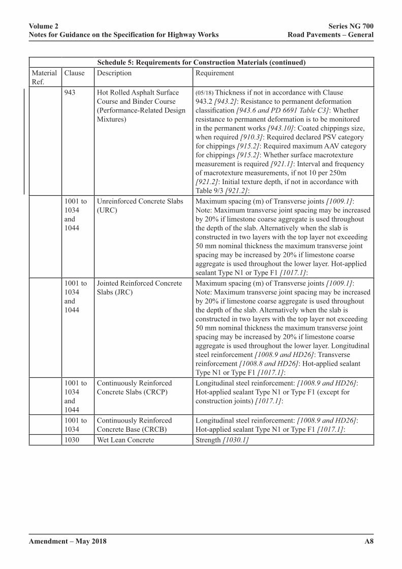
943 Hot Rolled Asphalt Surface Course and Binder Course (Performance-Related Design Mixtures)
(05/18) Thickness if not in accordance with Clause 943.2 [943.2]: Resistance to permanent deformation classification [943.6 and PD 6691 Table C3]: Whether resistance to permanent deformation is to be monitored in the permanent works [943.10]: Coated chippings size, when required [910.3]: Required declared PSV category for chippings [915.2]: Required maximum AAV category for chippings [915.2]: Whether surface macrotexture measurement is required [921.1]: Interval and frequency of macrotexture measurements, if not 10 per 250m [921.2]: Initial texture depth, if not in accordance with Table 9/3 [921.2]:
1001 to 1034 and 1044
Unreinforced Concrete Slabs (URC)
Maximum spacing (m) of Transverse joints [1009.1]: Note: Maximum transverse joint spacing may be increased by 20% if limestone coarse aggregate is used throughout the depth of the slab. Alternatively when the slab is constructed in two layers with the top layer not exceeding 50 mm nominal thickness the maximum transverse joint spacing may be increased by 20% if limestone coarse aggregate is used throughout the lower layer. Hot-applied sealant Type N1 or Type F1 [1017.1]:
1001 to 1034 and 1044
Jointed Reinforced Concrete Slabs (JRC)
Maximum spacing (m) of Transverse joints [1009.1]: Note: Maximum transverse joint spacing may be increased by 20% if limestone coarse aggregate is used throughout the depth of the slab. Alternatively when the slab is constructed in two layers with the top layer not exceeding 50 mm nominal thickness the maximum transverse joint spacing may be increased by 20% if limestone coarse aggregate is used throughout the lower layer. Longitudinal steel reinforcement [1008.9 and HD26]: Transverse reinforcement [1008.8 and HD26]: Hot-applied sealant Type N1 or Type F1 [1017.1]:
1001 to 1034 and 1044
Continuously Reinforced Concrete Slabs (CRCP)
Longitudinal steel reinforcement: [1008.9 and HD26]: Hot-applied sealant Type N1 or Type F1 (except for construction joints) [1017.1]:
1001 to 1034
Continuously Reinforced Concrete Base (CRCB)
Longitudinal steel reinforcement: [1008.9 and HD26]: Hot-applied sealant Type N1 or Type F1 [1017.1]:
1030 Wet Lean Concrete Strength [1030.1]
A9
Volume 2 Series NG 700 Notes for Guidance on the Specification for Highway Works Road Pavements – General
Amendment – May 2018
6 (02/16) THIN SURFACE COURSE SYSTEMS: INFORMATION TO BE PROVIDED BY THE CONTRACTOR – SCHEDULE 6
[Note to Contractor: Complete one sheet per system or variant of system that may be used]
(05/18) The Contractor shall provide the following information with his tender:
(i) The declaration of performance for the thin surface course system.
(ii) The declaration of performance for the aggregate(s) used in the thin surface course system.
(iii) The Installation Method Statement as required in sub-Clause 942.13.
(iv) SIPT documentation as required in sub-Clause 942.29.
(v) If regulating material is to be used, evidence of its deformation resistance either independently or in combination with the Thin Surface Course System [942.12]
7 (05/18) BINDER DATA REQUIREMENTS [937.3 and 943.4] – SCHEDULE 7
(05/18) The following data shall be provided to the Overseeing Organisation for modified binders as required in sub-Clauses 937.3 and 943.4. The data should not be more than 12 months old. A table in which the binder data may be recorded is given at the end of this section.
For work carried out for the Overseeing Organisation in England, a copy of the results should be handed to the Overseeing Organisation.
I. Binder Samples
Bituminous binders shall be sampled according to BS EN 58. For modifiers blended with the other component materials of the mixture at the mixer a simulated binder shall be prepared. Such modifiers are generally less intimately mixed with the bitumen and less well dispersed throughout the mixture than when pre-blended. Evidence that the simulated binder offers the same performance as the binder produced when the modifier is added at the mixer shall be provided.
II. Penetration
Binder penetration at 25°C (BS EN 1426), 100g 5 seconds for the binders as supplied, after hardening in the Rolling Thin Film Oven Test (RTFOT) in accordance with BS EN 12607-1, and after RTFOT and Ageing in the Pressure Ageing Vessel at 85 C (PAV85) in accordance with BS EN 14769.
III. Product Identification Test and Rheological Properties
Results for the binder(s) proposed shall comprise rheological data for each binder in the form of complex shear (stiffness) modulus (G*) and phase angle (δ delta) determined in accordance with BS EN 14770 for binder as supplied, after RTFOT and after RTFOT BS EN 12607-1 and PAV85 Ageing in accordance with BS EN 14769.
IV. Storage Stability Test
All binders shall be stored strictly in accordance with the manufacturer’s instructions. Polymer modified binders claimed to remain homogeneous in storage without agitation shall be tested for storage stability in accordance with BS EN 13399. The mean of the differences in softening point between the top and bottom samples, of not less than five pairs of such samples shall not exceed 5°C. Manufacturers of pre- blended modified binders shall state what precautions are necessary to ensure that adequate homogeneity is maintained during storage.

A10
Volume 2 Series NG 700 Notes for Guidance on the Specification for Highway Works Road Pavements – General
Amendment – May 2018
V. Photomicrograph
A typical photomicrograph of the modified binder and binder using ultra-violet or other technique to provide maximum contrast of the polymer structure to the binder before modification shall be supplied together with details of sample preparation techniques. A photomicrograph is intended only to indicate the presence of a polymer modifier in the binder and should not be used as an indicator of performance. Guidance on the interpretation of photomicrographs is given in BS EN 13632 Visualisation of polymer dispersion in polymer modified bitumen.
VI. Cohesion
Vialit Pendulum cohesion test curve of the binder, in accordance with BS EN 13588 for the binder as supplied, after RTFOT BS EN 12607-1, and after RTFOT and PAV85 Ageing in accordance with BS EN 14769.
VII. FRAASS Brittle Point
FRAASS brittle point measured using BS EN 12593 shall be provided on the binder as supplied, after RTFOT and after RTFOT and PAV85 Ageing in accordance with BS EN 14769.
(05/18) Summary of binder dataManufacturer of Binder:Product nameBatch refBinder type:Binder source:Softening point difference in storage stability testTest Supplied binder After RTFOT After RTFOT
and PAV85Penetration at 25°C 0,1 mm (100g and 5 secs)Penetration at 5°C 0,1 mm (200g and 60 secs)Vialit pendulum cohesion maximum peak value J/cm2 # # #Product identification test # # #Complex shear (stiffness) modulus (G*) and phase angle (δ) data. Fraass brittle pointOther properties the Contractor considers useful
Where indicated with # the Contractor shall attach a graphical output to this schedule.
8 (05/18) MIXTURE DATA REQUIREMENTS – SCHEDULE 8
The following data should be provided to the Overseeing Organisation for materials designed in accordance with Clause 901.17 and Clause 929 in respect of the proposed mixture.
For work carried out for Highways England, a copy of the results should be handed to the Overseeing Organisation, to be forwarded to: Pavement Engineering Team at Highways England, Woodlands, Manton Lane, Manton Industrial Estate, Bedford, MK41 7LW.

Amendment – February 2016 A11
Volume 2 Series NG 700 Notes for Guidance on the Specification for Highway Works Road Pavements – General
(02/16) NG SAMPLE CONTRACT SPECIFIC APPENDIX 7/2: EXCAVATION, TRIMMING AND REINSTATEMENT OF EXISTING SURFACES[Note to compiler: Include here:]
1 (02/16) Locations of any trenches, pits, etc, which require to be excavated in existing paved surfaces in order to carry out the Works. Reference to any drawings giving further details. [706.2]
2 (02/16) Locations and estimated areas of existing paved areas which require to be trimmed, regulated and reinstated to match levels where new and existing pavements abut or where new construction overlays existing pavement. Reference to contract specific Appendices 7/1 and 7/9, and to any drawings giving further details [706.2, 706.9]. Acceptable material for reinstating other areas [706.8].
3 (02/16) Cross-section diagram of typical trench reinstatement in bituminous and concrete pavements giving details of materials. [Examples are given in HCD Drawing Number K4.]
4 (02/16) References to drawings which show construction at junctions between the following pavement materials. [706.10]
(i) concrete/concrete,
(ii) concrete/bituminous,
(iii) concrete/porous asphalt,
(iv) bituminous/porous asphalt,
(v) bituminous/bituminous,
(vi) porous asphalt/porous asphalt
For junctions with porous asphalt see HD 37 Bituminous Surfacing Materials and Techniques (DMRB 7.5.2).
5 (02/16) Full depth repairs and reinstatements
(i) Repair criteria if different from sub-Clause 1033.4
(ii) Requirement for full bay replacement [1033.7]
(iii) (mm/yy) Reinstated subbase material [1033.9]
(iv) Stitched crack repair type [1033.12]
(v) Filling of slots [1033.13]
(vi) Longitudinal joint grooves to be re cut [1033.15]
(vii) Transverse joint grooves to be re cut [1033.16]
6 (02/16) Joint Seals
(i) Colour of the joint seal material [1017.1]
A12
Volume 2 Series NG 700 Notes for Guidance on the Specification for Highway Works Road Pavements – General
Amendment – May 2018
(02/16) NG SAMPLE CONTRACT SPECIFIC APPENDIX 7/3: SURFACE DRESSING – PERFORMANCE SPECIFICATION
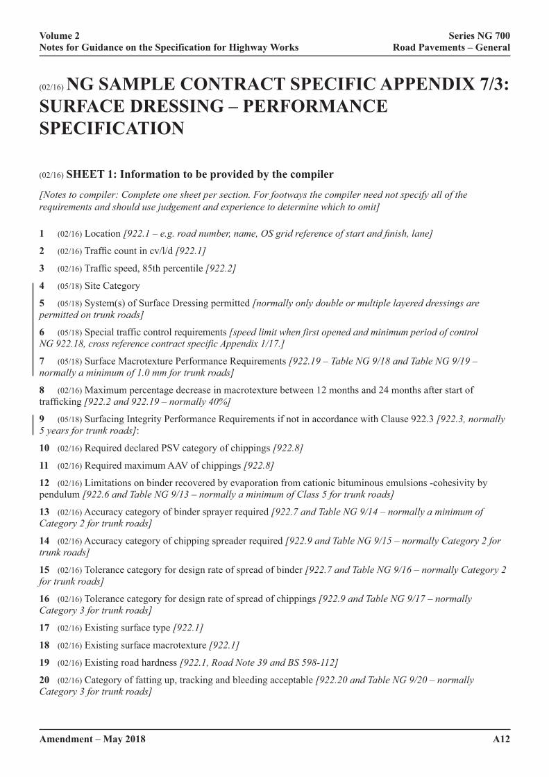
(02/16) SHEET 1: Information to be provided by the compiler
[Notes to compiler: Complete one sheet per section. For footways the compiler need not specify all of the requirements and should use judgement and experience to determine which to omit]
1 (02/16) Location [922.1 – e.g. road number, name, OS grid reference of start and finish, lane]
2 (02/16) Traffic count in cv/l/d [922.1]
3 (02/16) Traffic speed, 85th percentile [922.2]
4 (05/18) Site Category
5 (05/18) System(s) of Surface Dressing permitted [normally only double or multiple layered dressings are permitted on trunk roads]
6 (05/18) Special traffic control requirements [speed limit when first opened and minimum period of control NG 922.18, cross reference contract specific Appendix 1/17.]
7 (05/18) Surface Macrotexture Performance Requirements [922.19 – Table NG 9/18 and Table NG 9/19 – normally a minimum of 1.0 mm for trunk roads]
8 (02/16) Maximum percentage decrease in macrotexture between 12 months and 24 months after start of trafficking [922.2 and 922.19 – normally 40%]
9 (05/18) Surfacing Integrity Performance Requirements if not in accordance with Clause 922.3 [922.3, normally 5 years for trunk roads]:
10 (02/16) Required declared PSV category of chippings [922.8]
11 (02/16) Required maximum AAV of chippings [922.8]
12 (02/16) Limitations on binder recovered by evaporation from cationic bituminous emulsions -cohesivity by pendulum [922.6 and Table NG 9/13 – normally a minimum of Class 5 for trunk roads]
13 (02/16) Accuracy category of binder sprayer required [922.7 and Table NG 9/14 – normally a minimum of Category 2 for trunk roads]
14 (02/16) Accuracy category of chipping spreader required [922.9 and Table NG 9/15 – normally Category 2 for trunk roads]
15 (02/16) Tolerance category for design rate of spread of binder [922.7 and Table NG 9/16 – normally Category 2 for trunk roads]
16 (02/16) Tolerance category for design rate of spread of chippings [922.9 and Table NG 9/17 – normally Category 3 for trunk roads]
17 (02/16) Existing surface type [922.1]
18 (02/16) Existing surface macrotexture [922.1]
19 (02/16) Existing road hardness [922.1, Road Note 39 and BS 598-112]
20 (02/16) Category of fatting up, tracking and bleeding acceptable [922.20 and Table NG 9/20 – normally Category 3 for trunk roads]

A13
Volume 2 Series NG 700 Notes for Guidance on the Specification for Highway Works Road Pavements – General
Amendment – May 2018
21 (02/16) Category of scabbing and tearing acceptable [922.20 and Table NG 9/21 – normally Category 2 for trunk roads]
22 (02/16) Category of fretting [922.20 and Table NG 9/22 – normally Category 3 for trunk roads]
23 (02/16) Category of streaking [922.20 and Table NG 9/23 – normally Category 3 for trunk roads]
24 (02/16) Special restrictions [922.13, 922.15 and 922 .16 – for example: maximum road surface temperature at which working permitted is 40ºC]
(02/16) SHEET 2: Information to be provided by the Contractor
The Contractor shall provide the following information with his tender:
1 (05/18) The declaration of performance for the surface dressing in accordance with BS EN 12271. [922.2, 922.4]
2 (05/18) Proposed binders together with their declaration(s) of performance as specified. [922.5 and 922.6] [Note to compiler: A suitable Sheet for the provision of binder data is attached to this sample Appendix, other layouts are permitted but all the required data should be supplied]
3 (05/18) A method statement for each site or group of similar sites showing how it is proposed to carry out the works in conformance with the specification. [The Contractor will be expected to commit enough resources to carry out the proposed design in one single continuous pass, for example, if a double dressing is proposed on a heavily trafficked road then 2 sprayers, 2 chip spreaders, 2 rollers and 2 sweepers will be a minimum requirement. The type of plant, age and number should be detailed for example 2 computer controlled sprayers three years old].
4 (05/18) Proposals for traffic control and aftercare for each site, and reaction times for carrying out remedial measures, sweeping and site visits with the Overseeing Organisation. [922.12, 922.15, 922.16, 922.17]
5 (05/18) Contingency plans in the event of any breakdown of plant or failure of the dressing and provision for dusting. [922.16]
6 (05/18) A statement of relevant experience and expertise, naming managers supervisors and teams responsible for and allocated to the Contract. [922.4]
7 (05/18) Design proposal for Surface Dressing for each location. [922.2]
8 (05/18) Estimated design life of the Surface Dressing for each location. [922.2]
9 (05/18) For the performance specification, the results of any other tests or other data the Contractor considers would assist the Overseeing Organisation in assessing the technical merit of the design.
10 (05/18) An ‘As Built Manual’ as specified. [922.18]

A14
Volume 2 Series NG 700 Notes for Guidance on the Specification for Highway Works Road Pavements – General
Amendment – May 2018
NG SAMPLE CONTRACT SPECIFIC APPENDIX 7/4: BOND COATS, TACK COATS AND OTHER BITUMINOUS SPRAYS(02/16) SHEET 1: Information to be provided by the compiler [Note to compiler: Complete one sheet per section]
1 (02/16) Location. drawing reference number [920.1 – eg road number, name, OS grid reference of start and finish, lane, etc]
2 (05/18) Performance characteristics to be demonstrated by the declaration(s) of performance [920.2, 920.3, 920.4].
3 (05/18) Site specific limitations [Note: any access restrictions, timing constraints etc should be specified in contract specific Appendix 1/13]
4 (05/18) Type of treatment required and details of the existing surface and overlay material [920.1 and 903.4 eg bond coat: premium grade, intermediate grade, non-tack type with or without breaking control; tack coat and type permitted for the overlay; or other bituminous spray]
5 (05/18) Surface preparation required [920.6]
6 (05/18) Masking of street furniture, drop-kerbs, etc. [920.6]
7 (05/18) Rate of spread required [920.8 with appropriate adjustment for variable surface characteristics]
8 (05/18) Type of blinding material to be used [920.13]

A15
Volume 2 Series NG 700 Notes for Guidance on the Specification for Highway Works Road Pavements – General
Amendment – May 2018
(02/16) SHEET 2: Information to be provided by the Contractor
The Contractor shall provide the following information with his tender, or prior to the commencement of the work:
1 (05/18) The product or products he proposes to use together with their declaration(s) of performance, as specified. [920.2, 920.3, 920.4, 920.5]
2 (02/16) For each product, a copy of the BS EN ISO 9001 certificate showing the name of the manufacturer, the name of the certification body and the reference number and date of the certificate.
3 (02/16) The spraying equipment proposed, and a test certificate. [920.7, 920.9]
4 (02/16) The source or sources of blinding material proposed. [920.12]
5 (02/16) Contingency plans in the event of any breakdown.
A16
Volume 2 Series NG 700 Notes for Guidance on the Specification for Highway Works Road Pavements – General
Amendment – May 2018
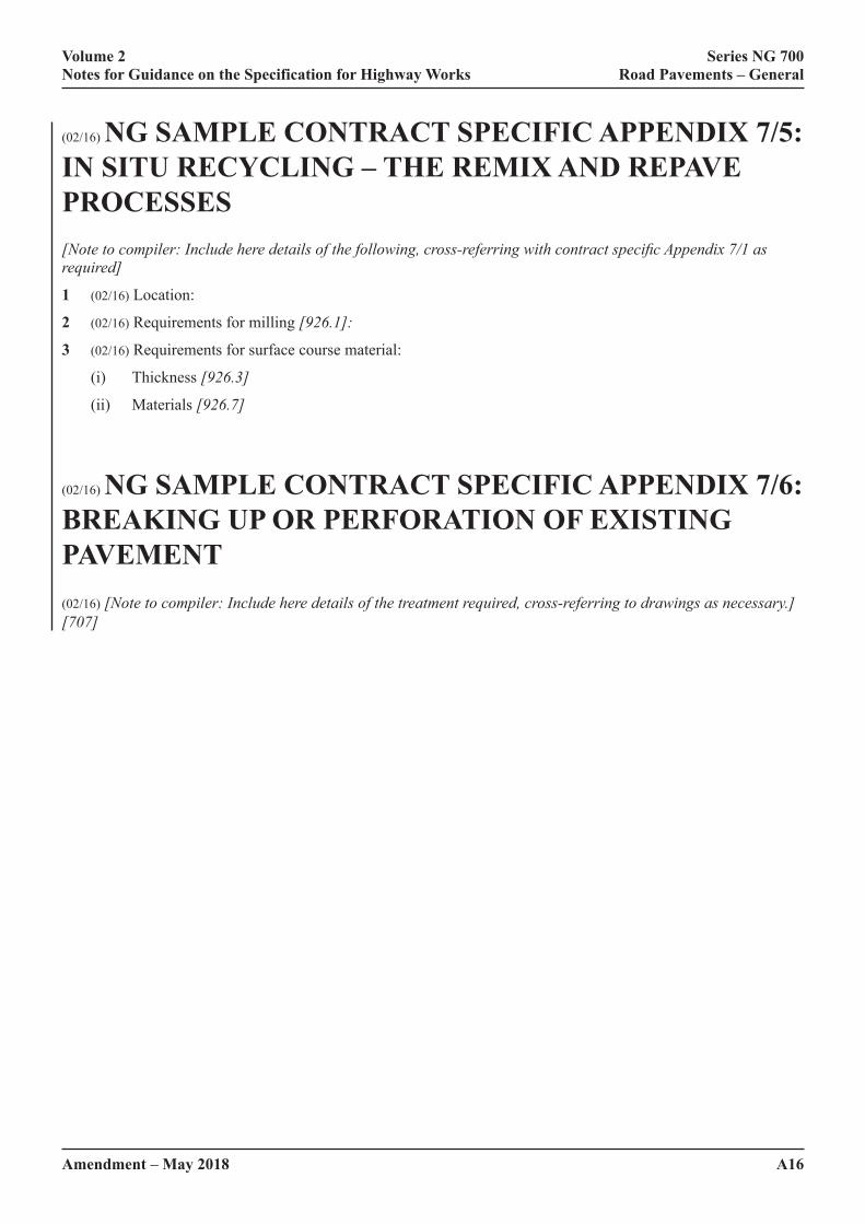
(02/16) NG SAMPLE CONTRACT SPECIFIC APPENDIX 7/5: IN SITU RECYCLING – THE REMIX AND REPAVE PROCESSES[Note to compiler: Include here details of the following, cross-referring with contract specific Appendix 7/1 as required]
1 (02/16) Location:
2 (02/16) Requirements for milling [926.1]:
3 (02/16) Requirements for surface course material:
(i) Thickness [926.3]
(ii) Materials [926.7]
(02/16) NG SAMPLE CONTRACT SPECIFIC APPENDIX 7/6: BREAKING UP OR PERFORATION OF EXISTING PAVEMENT(02/16) [Note to compiler: Include here details of the treatment required, cross-referring to drawings as necessary.][707]
A17
Volume 2 Series NG 700 Notes for Guidance on the Specification for Highway Works Road Pavements – General
Amendment – May 2018
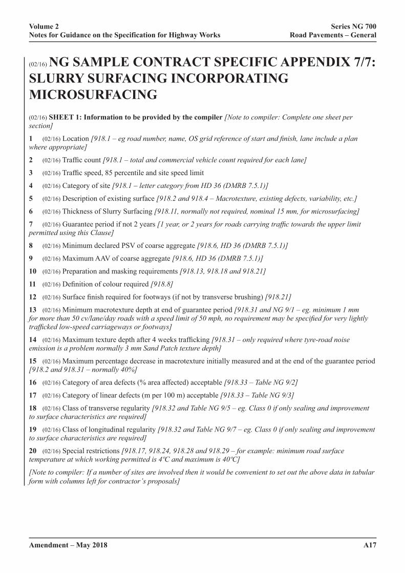
(02/16) NG SAMPLE CONTRACT SPECIFIC APPENDIX 7/7: SLURRY SURFACING INCORPORATING MICROSURFACING(02/16) SHEET 1: Information to be provided by the compiler [Note to compiler: Complete one sheet per section]
1 (02/16) Location [918.1 – eg road number, name, OS grid reference of start and finish, lane include a plan where appropriate]
2 (02/16) Traffic count [918.1 – total and commercial vehicle count required for each lane]
3 (02/16) Traffic speed, 85 percentile and site speed limit
4 (02/16) Category of site [918.1 – letter category from HD 36 (DMRB 7.5.1)]
5 (02/16) Description of existing surface [918.2 and 918.4 – Macrotexture, existing defects, variability, etc.]
6 (02/16) Thickness of Slurry Surfacing [918.11, normally not required, nominal 15 mm, for microsurfacing]
7 (02/16) Guarantee period if not 2 years [1 year, or 2 years for roads carrying traffic towards the upper limit permitted using this Clause]
8 (02/16) Minimum declared PSV of coarse aggregate [918.6, HD 36 (DMRB 7.5.1)]
9 (02/16) Maximum AAV of coarse aggregate [918.6, HD 36 (DMRB 7.5.1)]
10 (02/16) Preparation and masking requirements [918.13, 918.18 and 918.21]
11 (02/16) Definition of colour required [918.8]
12 (02/16) Surface finish required for footways (if not by transverse brushing) [918.21]
13 (02/16) Minimum macrotexture depth at end of guarantee period [918.31 and NG 9/1 – eg. minimum 1 mm for more than 50 cv/lane/day roads with a speed limit of 50 mph, no requirement may be specified for very lightly trafficked low-speed carriageways or footways]
14 (02/16) Maximum texture depth after 4 weeks trafficking [918.31 – only required where tyre-road noise emission is a problem normally 3 mm Sand Patch texture depth]
15 (02/16) Maximum percentage decrease in macrotexture initially measured and at the end of the guarantee period [918.2 and 918.31 – normally 40%]
16 (02/16) Category of area defects (% area affected) acceptable [918.33 – Table NG 9/2]
17 (02/16) Category of linear defects (m per 100 m) acceptable [918.33 – Table NG 9/3]
18 (02/16) Class of transverse regularity [918.32 and Table NG 9/5 – eg. Class 0 if only sealing and improvement to surface characteristics are required]
19 (02/16) Class of longitudinal regularity [918.32 and Table NG 9/7 – eg. Class 0 if only sealing and improvement to surface characteristics are required]
20 (02/16) Special restrictions [918.17, 918.24, 918.28 and 918.29 – for example: minimum road surface temperature at which working permitted is 4ºC and maximum is 40ºC]
[Note to compiler: If a number of sites are involved then it would be convenient to set out the above data in tabular form with columns left for contractor’s proposals]

A18Amendment – February 2016
Volume 2 Series NG 700 Notes for Guidance on the Specification for Highway Works Road Pavements – General
(02/16) SHEET 2: Information to be provided by the Contractor:
1 (05/18) The declaration of performance for the slurry surfacing in accordance with BS EN 12273. [918.2, 918.4]
2 (02/16) Design Proposal for Slurry Surfacing for each location and target binder content with tolerances. [918.2]
3 (02/16) Estimated Design Life of the Slurry Surfacing for each location. [918.2]
4 (05/18) A method statement for each site or group of similar sites showing how it is proposed to carry out the works in conformance with the specification. [Contractors will be expected to commit enough resources to carry out the proposed design; the type and age of the Slurry Surfacing Machine should be detailed].
5 (05/18) Proposed performance categories of the coarse aggregate together with statements of properties including target grading, declared PSV and AAV. [918.65]
6 (05/18) Proposed performance categories of the fine aggregate including target grading and other constituents together with statements of properties. [918.5]
7 (05/18) Proposed binder declaration of performance [918.5].
8 (05/18) Proposals for traffic control and aftercare for each site, and reaction times for: carrying out remedial measures; sweeping; and site visits with the Overseeing Organisation. [918 14, 918.17, 918.28]
9 (05/18) Contingency plans in the event of any breakdown of plant or failure of the Slurry Surfacing. [918.27]
10 (05/18) An ‘As Built Manual’ as specified. [918.29]
11 (05/18) If available any other data provided in order to assist the Overseeing Organisation to assess the technical merits of the Design Proposal:
Amendment – February 2016 A19
Volume 2 Series NG 700 Notes for Guidance on the Specification for Highway Works Road Pavements – General
(02/16) NG SAMPLE CONTRACT SPECIFIC APPENDIX 7/8: NOT USED
(02/16) NG SAMPLE CONTRACT SPECIFIC APPENDIX 7/9: COLD-MILLING (PLANING) OF BITUMINOUS BOUND FLEXIBLE PAVEMENT[Note to compiler: Include here details of:]
1 (02/16) Cross reference to contract specific Appendix 7/2 listing the drawings identifying where cold-milling is required.
2 (02/16) For each location where cold-milling is required specify whether profile planing or constant depth planing is required, giving details of the alignments or depths as appropriate [709.1] The location references should correspond with those listed in contract specific Appendix 7/1.
3 (02/16) Sweeping of areas prior to cold-milling. [709.11]
Schedule: Sweeping Areas Prior to Cold-millingDrawing No. Location
(02/16) NG SAMPLE CONTRACT SPECIFIC APPENDIX 7/10: NOT USED

A20
Volume 2 Series NG 700 Notes for Guidance on the Specification for Highway Works Road Pavements – General
Amendment – May 2018
(02/16) NG SAMPLE CONTRACT SPECIFIC APPENDIX 7/11: OVERBAND AND INLAID CRACK SEALING SYSTEMS[Note to compiler: Include here details of:]
1 (05/18) BBA/HAPAS or equivalent product acceptance scheme Grade Classification required for each location [711.4]
2 (02/16) The minimum polished stone value of the source aggregate for chippings [711.5]
(02/16) NG SAMPLE CONTRACT SPECIFIC APPENDIX 7/12: ARRESTER BEDS(02/16) [Note to compiler: List in the table below the location and area of each arrester bed to be maintained on the Network; ][712]
Reg No Location Frequency Area
Amendment – February 2016 A21
Volume 2 Series NG 700 Notes for Guidance on the Specification for Highway Works Road Pavements – General
(02/16) NG SAMPLE CONTRACT SPECIFIC APPENDIX 7/13: SAW-CUT AND SEAL BITUMINOUS OVERLAYS ON EXISTING JOINTED CONCRETE PAVEMENTS[Note to compiler: Include here details of the following]
1 (02/16) Location: The Drawing(s) to which reference is made in sub-Clause 713.1 are:[Compiler to complete]
2 (02/16) Whether the requirement of sub-Clause 713.2 shall applyBituminous overlays to be removed: Bituminous overlays are to be removed from cementitious pavements to be repaired prior to re-overlay as follows:
Location (Chainage x to y) Nominal thickness (mm)
3 (02/16) Dimensions of saw-cuts: [713.7] [Compiler see Figure 7/1]
4 (02/16) Tolerances on saw-cuts: [713.7]
(i) Plan position of the centre line of the sealant slot and of the crack-initiation slot relative to the centre line of the existing joint.
[Compiler: State whether ±5 mm or ±10 mm see NG 713.8]
(ii) Width of sealant slot. [Compiler see Figure 7/1]
(iii) Width of crack initiation slot. [Compiler see Figure 7/1]

A22
Volume 2 Series NG 700 Notes for Guidance on the Specification for Highway Works Road Pavements – General
Amendment – May 2018
(02/16) NG SAMPLE CONTRACT SPECIFIC APPENDIX 7/14: PREPARATION OF JOINTED CONCRETE PAVEMENTS PRIOR TO OVERLAYING AND SAW-CUT AND SEAL OF THE BITUMINOUS OVERLAY[Note to compiler: Items (3) and (4) below are included as a means of providing ‘as built’ data on the underlying pavement which will be saw-cut and sealed under Clause 714. Depending on where the risks lay, if it is considered that this data need not be provided to tenderers/contractors it may be deleted]
1 (02/16) Location: The drawing(s) to which reference is made in sub-Clause 714.1 are:……………………..[Compiler to complete]
2 (02/16) Existing cementitious pavement layer to be treated:
Location (Chainage x to y) Nominal thickness (mm) Strength range: (yy-zz) (MPa)
3 (02/16) Existing subbase and earthworks materials beneath the cementitious pavement layer:
Location (Chainage x to y) Subbase type and thickness
Capping type and thickness
Subgrade
See borehole and trial pit information [give name of document] listed in contract specific Appendix 0/4.
4 (02/16) Concrete Repair Processes[Note to Compiler: Based on the following repair techniques (eg.), insert below a schedule of repair work which it is certain will be needed to be carried out, giving also its location by reference to carriageway direction, chainage, bay no. etc. Include some reference on work instructions contingent on what is found during inspections made after milling off the existing bituminous overlay.
(i) Re-sealing joint grooves
(ii) Part-bay repairs
(iii) Thin bonded joint arris repair
(iv) Full depth repair procedure for jointed slabs
(v) Full depth repair procedure for continuously reinforced slabs and bases (at ends of proposed bituminous overlay)
(vi) Full depth repair to longitudinal cracks
(vii) Stitched crack repair procedure

Amendment – February 2016 A23
Volume 2 Series NG 700 Notes for Guidance on the Specification for Highway Works Road Pavements – General
(viii) Slab lifting
(ix) Pressure grouting
(x) Bay replacement repair procedure
(xi) Joint connectors (to transfer load across joints)
(xii) Sealing cracks
(xiii) Checks on load transfer between slabs may be required in order to determine what repair technique(s) is/are necessary.]
5 (02/16) Bond Coat:
(i) (02/16) The treated surface should be bond coated in accordance with contract specific Appendix 7/4 prior to overlaying.

A24Amendment – February 2016
Volume 2 Series NG 700 Notes for Guidance on the Specification for Highway Works Road Pavements – General
(02/16) NG SAMPLE CONTRACT SPECIFIC APPENDIX 7/15: SAW-CUT, CRACK AND SEAT EXISTING JOINTED REINFORCED CONCRETE PAVEMENTS[Note to compiler: Include here details of the following][715]
1 (02/16) Location: The Drawing(s) to which reference is made in sub-Clause 715.1 are:[Compiler to complete]
(i) A main trial area (or areas) of saw-cut, cracking and seating shall be carried out in accordance with sub-Clause 715.21 and shall be assessed in accordance with sub-Clause 715.22 at a location or at locations selected by the Overseeing Organisation to establish (i) the depth of saw-cutting, (ii) the depth and severity of induced cracking, (iii) the settings of the crack inducing equipment to produce the specified cracking, and (iv) the spacing of the saw-cuts for the main production work.
2 (02/16) Existing asphalt overlays are to be removed from surfaces to be treated as follows.
(i) Chainage …* to …* ...* mm nominal thickness
(ii) Chainage …* to …* …* mm nominal thickness
[Compiler to complete *]
3 (02/16) Existing concrete pavement layer to be cracked:
(i) Nominal thickness:
(a) Chainage …* to …* ...* mm
(b) Chainage …* to …* ...* mm
etc
(ii) Position of longitudinal …* mm cover below surface ± …* mm reinforcement:
(iii) Diameter of longitudinal …* mm reinforcement:
(iv) Strength range of existing concrete: * - * MPa
(v) Design effective stiffness threshold for locations:
(a) Chainage …* to …* * - * MPa
(b) Chainage …* to …* * - * MPa
[Compiler to complete *]
4 (02/16) Existing subbase and earthworks materials beneath the concrete pavement layer:
(i) Chainage …* to …* ...* mm subbase type …* ...* mm capping Subgrade – see data below

Amendment – February 2016 A25
Volume 2 Series NG 700 Notes for Guidance on the Specification for Highway Works Road Pavements – General
(ii) Chainage …* to …* ...* mm subbase type …* ...* mm capping Subgrade – see data below
[Compiler to complete/amend as appropriate *]
See borehole and trial pit information [Compiler to give name of document] listed in contract specific Appendix 0/4.
5 (02/16) FWD Testing & Measurements:
(i) Whether FWD testing of effective stiffness is required: ... Yes/No*
(ii) Whether FWD testing of joint efficiency is required: … Yes/No*
(iii) FWD measurements: For effective stiffness, carried out by the Contractor in accordance with Clause 718
(iv) FWD assessment: For effective stiffness, carried out by the Contractor in accordance with Clause 719
6 (02/16) Saw-cuts:
(i) Spacing of saw-cuts to be used: 1 metre adjacent to each joint and equally spaced at * metres c/c (not exceeding 5-8 m) to suit a bay length.
(ii) Width of saw-cut: 3 mm
(iii) Tolerance on spacing of transverse saw-cuts: ± 50 mm
(iv) Tolerance on depth of transverse +20 mm -0 mm and not greater than * % of saw-cuts below base of reinforcement: nominal pavement slab depth.
(v) Not within 500 mm of any existing transverse joint or crack in that lane.
[Compiler to complete*]
7 Cracking:
(i) Type of crack: The induced cracks shall be single, predominantly vertical from the bottom of the saw-cut to the bottom of the concrete pavement slab with no shattering or multiple cracking.
(ii) Location of the impacting head No closer than 0.5 m from any edge of the concrete of the crack-inducing equipment: slabs.

A26Amendment – February 2016
Volume 2 Series NG 700 Notes for Guidance on the Specification for Highway Works Road Pavements – General
8 (02/16) Assessment of Cracking:
(i) Core diameter: Not less than …* mm diameter.
(ii) Depth of core: Full depth of the reinforced concrete layer.
(iii) Frequency of coring 1 core every 300 m2. for main production work:
(iv) For Stage 2 of main trial 1 core every alternate transverse saw-cut. and any subsequent trials:
[Compiler to complete*]
9 (02/16) Seating:
(i) Minimum weight of roller: …* tonnes [Not less than 20 tonnes]
(ii) Number of passes on main Not less than …* passes shall be applied. production work:
[Compiler to complete*]
(iii) Number of passes on main work: Not less than 6** passes of the specified roller shall be applied at every point.
[**Compiler may increase if necessary]
10 (02/16) Ground Penetrating Radar (GPR)
(i) Data to be supplemented by GPR: … [Yes or No]

Amendment – February 2016 A27
Volume 2 Series NG 700 Notes for Guidance on the Specification for Highway Works Road Pavements – General
(02/16) NG SAMPLE CONTRACT SPECIFIC APPENDIX 7/16: CRACKING AND SEATING OF EXISTING JOINTED UNREINFORCED CONCRETE PAVEMENTS AND HYDRAULICALLY BOUND MIXTURE (HBM) BASES[Note to compiler: Include here details of the following][716]
1 (02/16) Location
The drawing(s) to which reference is made in sub-Clause 716.1 are:
Drawings Nos. …………………
[Compiler to complete]
A main trial area (or areas) of cracking and seating shall be carried out in accordance with sub-Clause 716.17 and shall be assessed in accordance with sub-Clause 716.18 at a location or at locations selected by the Overseeing Organisation to establish (i) the crack pattern, (ii) the depth and severity of cracking, (iii) the settings of the crack inducing equipment to produce the specified cracking and (iv) the spacing of the cracks for the main work. A production cracking re-assessment trial shall be carried out when necessary in accordance with sub-Clause 716.28 at a location selected by the Overseeing Organisation to re-establish (a) the crack pattern, (b) the depth and severity of cracking, (c) the settings of the crack inducing equipment to produce the specified cracking, and (d) the spacing of the transverse cracks for the main work remaining.
2 (02/16) Existing asphalt overlays are to be removed from surfaces to be treated as follows.
(i) Chainage …* to …* ...* mm nominal thickness
(ii) Chainage …* to …* ...* mm nominal thickness
[Compiler to complete *]
3 (02/16) Existing hydraulically bound pavement layer(s) to be cracked:
(i) Nominal thickness:
(a) Chainage …* to …* ...* mm
(b) Chainage …* to …* ...* mm
etc
[Compiler to complete*]
(ii) Comprehensive strength range:
(a) Chainage …* to …* ...* MPa
A28Amendment – February 2016
Volume 2 Series NG 700 Notes for Guidance on the Specification for Highway Works Road Pavements – General
(b) Chainage …* to …* ...* MPa
etc
[Compiler to complete*]
(iii) Design effective stiffness threshold for locations:
(a) Chainage …* to …* ...* MPa
(b) Chainage …* to …* ...* MPa
etc
[Compiler to complete*]
4 (02/16) Existing subbase and earthworks materials beneath the hydraulically bound pavement layer:
(i) Chainage …* to …* ...* mm subbase type …* ...* mm capping Subgrade – see data below
(ii) Chainage …* to …* ...* mm subbase type …* ...* mm capping Subgrade – see data below
[Compiler to complete/amend as appropriate*]
See borehole and trial pit information [Compiler to give name of document] listed in contract specific Appendix 0/4.
5 (02/16) Cracking:
(i) Spacing of transverse cracks for the main trial: (a)…* m (b)…* m (c)…* m
[Compiler to complete*]
(ii) Spacing of transverse cracks for the As directed by the Overseeing Organisation. production cracking re-assessment trial:
(iii) Spacing of transverse cracks for the main Determined from the main trial or from a works: production cracking re-assessment trial.
(iv) Tolerance on spacing of transverse cracks: ± 5%
(v) Category of transverse cracks (based on Fine ie < 0.5 mm wide. width observed at the surface)
(vi) Depth of cracks: Full depth of hydraulically bound pavement layer.
(vii) Type of crack: The induced cracks shall be single, predominantly vertical through the layer with no shattering or multiple cracking.
(viii) Location of impacting head of the No closer than 0.5 m from any edge of the concrete crack-inducing equipment: bays or HBM base.
(ix) Tolerance of transverse alignment ± 50 mm

Amendment – February 2016 A29
Volume 2 Series NG 700 Notes for Guidance on the Specification for Highway Works Road Pavements – General
6 (02/16) Assessment of Cracking:
(i) Core diameter: Not less than 150 mm diameter.
(ii) Depth of core: Full depth of the hydraulically bound layer or layers.
(iii) FWD measurements: Carried out by the Contractor in accordance with Clause 717.
(iv) FWD assessment: Carried out by the Contractor in accordance with Clause 719.
7 (02/16) Seating:
(i) Minimum weight of roller: … tonnes [Not less than 20 tonnes]
(ii) Number of passes on main work: …Not less than 6** passes of the specified roller shall be applied at every point.
[**Compiler may increase if necessary]
8 (02/16) Ground Penetrating Radar (GPR)
(i) Data to be supplemented by GPR: … [Yes or No]

A30Amendment – February 2016
Volume 2 Series NG 700 Notes for Guidance on the Specification for Highway Works Road Pavements – General
(02/16) NG SAMPLE CONTRACT SPECIFIC APPENDIX 7/17: CRACKING PLANT AND EQUIPMENT PROGRESS RECORDInformation to be provided by the Contractor
Sheet no......
Contract: (Road no. & name) .............................................................
Site location: .....................................................................................
Type of plant and Contractor’s plant number.......................................
Blade length .................metres Blade weight................kg
Month/year work commenced...................... Carriageway ..........bound eg E/W/N/S/
Date and time
Chainage and Lane no.
Height of Drop (mm)
Crack Spacing (m)
Notes For example: Changes in crack pattern and reasons for any adjustments made to weight, drop or other settings
Name of Contractor: ............…………………………...............[Block capitals]Signature of Contractor’s representative: ....………………..…..Date .…………...
Name and post of signatory: ...……………………….................[Block capitals]
Amendment – February 2016 A31
Volume 2 Series NG 700 Notes for Guidance on the Specification for Highway Works Road Pavements – General
(02/16) NG SAMPLE CONTRACT SPECIFIC APPENDIX 7/18: SITE SPECIFIC DETAILS AND REQUIREMENTS FOR COLD RECYCLED BITUMEN BOUND MATERIAL[Note to compiler: The following particulars should be read in conjunction with Clause 948]
1 (02/16) Site description, location details and depth of recycling:
(i) Overall location reference to plans
(ii) Section details reference to plans & sections
(iii) Location of services reference to plans & sections
(iv) Depth of recycled layer ...... mm
(v) Location and condition of drainage reference to plans & sections
(vi) Type and severity of deterioration reference to plans & sections
(vii) Subgrade bearing capacity and condition ……
(viii) Edge detail and verge condition reference to plans & sections
(ix) Future traffic loading ……
2 (02/16) Type of lime required for modification of cohesive soils ......
3 (02/16) Locations of stockpiles of excess pulverised materials awaiting re-use elsewhere …………..
4 (02/16) Rate of application of bitumen emulsion sealant spray ...... l/m2
5 (02/16) Minimum elastic modulus within 24 hours obtained using a dynamic plate or penetration test:Single point value ...... MPaMean value ...... MPaMinimum percentage increase of single point elastic modulus values ......%Minimum percentage increase of mean elastic modulus value ......%
6 (02/16) Absolute minimum added bitumen content
7 (02/16) Nominal grid pattern [947]
8 (02/16) Rolling mean of 10 FWD derived stiffness values shall not be less than………….. MPa and no individual result less than 85% of ...... MPa. [947.50]
A32Amendment – February 2016
Volume 2 Series NG 700 Notes for Guidance on the Specification for Highway Works Road Pavements – General
(02/16) NG SAMPLE CONTRACT SPECIFIC APPENDIX 7/19: BACK-ANALYSIS OF FALLING WEIGHT DEFLECTOMETER (FWD) MEASUREMENTS MADE ON CONCRETE PAVEMENTS TREATED BY FRACTURED SLAB TECHNIQUES1 (02/16) Software and documentation to be used in conjunction with this Clause:
(i) Version of MODULUS-HA to be used in back-analysis: 5.1*
(ii) Version of MODULUS-HA User’s Guide (MUG) to be 3.3* referred to in instructions for back-analysis:
(iii) The electronic format of the compiled back-analysed: Compatible with …* data to be supplied to the Overseeing Organisation for assessment:
[Compiler to amend/complete *]
2 (02/16) Back-analysis model to be used with MODULUS-HA: Two-layer only
3 (02/16) Drop number at each test position to be used in back-analysis: 3
4 (02/16) Geophone Weight Factors to be used in MODULUS-HA: Zero for all sensors
5 (02/16) Thickness of bound material (H1) to be used for the layers to be Derived from cores and modelled in MODULUS-HA: GPR measurements]*
[Compiler to amend*]
6 (02/16) Stiffness ranges to be used in MODULUS-HA for the layers to be modelled:
(i) Layer 1 (bound material): 500 – 50000* MPa
(ii) Most Probable Subgrade Modulus: 100* MPa
[Compiler to amend*]
7 (02/16) The values of Poisson’s ratio to be used for each layer to be modelled in MODULUS-HA are as follows:
(i) Hydraulically bound (including cracked and seated) 0.20
(ii) Combined granular foundation and subgrade 0.45
8 (02/16) The graphical presentation(s) of the back-analysed data arising from the Main Trial shall show the:
(i) Effective stiffness modulus of the hydraulically bound layer or layers before and after crack and seat
(ii) Stiffness modulus of the foundation layer before and after crack and seat
(iii) Crack spacing used at each FWD test position
The graphs showing the effective stiffness modulus of the hydraulically bound layer or layers shall also show the:
(iv) Effective stiffness design threshold specified in contract specific Appendix 7/17 appropriate at each test point.
(v) Location of any transverse cracks present before cracking and seating.
For jointed concrete pavements, the graphs should also give the:

Amendment – February 2016 A33
Volume 2 Series NG 700 Notes for Guidance on the Specification for Highway Works Road Pavements – General
(vi) Identification of the test point with lowest effective stiffness within each bay.
9 (02/16) The graphical presentation(s) of the back-analysed data arising from the Production Cracking shall show the:
(i) Effective stiffness modulus of the hydraulically bound layer or layers following crack and seat
(ii) Stiffness modulus of the foundation layer following crack and seat
The graphs showing the effective stiffness modulus of the hydraulically bound layers shall also show the:
(iii) Relevant effective threshold specified in contract specific Appendix 7/17 at each test point.
(iv) Location of any transverse cracks present before cracking and seating.
10 (02/16) The graphical presentation(s) of the back-analysed data arising from any Production Cracking reassessment trial shall show the:
(i) Effective stiffness modulus of the hydraulically bound layer or layers before and after crack and seat
(ii) Stiffness modulus of the foundation layer before and after crack and seat
(iii) Crack spacing used at each FWD test position
The graphs showing the effective stiffness modulus of the hydraulically bound layer or layers shall also show the:
(iv) Effective stiffness design threshold from contract specific Appendix 7/17 appropriate at each test point.
(v) Location of any transverse cracks present before cracking and seating.
For jointed concrete pavements, the graphs should give the:
(vi) Identification of the test point with lowest effective stiffness within each bay.
11 (02/16) Period of time for the Contractor to allow in his programme for 12 hours.* the Overseeing Organisation to assess and interpret submitted back-analysed results and prepare instructions:
[Compiler to amend*]

A34Amendment – February 2016
Volume 2 Series NG 700 Notes for Guidance on the Specification for Highway Works Road Pavements – General
(02/16) NG SAMPLE CONTRACT SPECIFIC APPENDIX 7/20: NOT USED

Amendment – February 2016 A35
Volume 2 Series NG 700 Notes for Guidance on the Specification for Highway Works Road Pavements – General
(02/16) NG SAMPLE CONTRACT SPECIFIC APPENDIX 7/21: SURFACE DRESSING – RECIPE SPECIFICATION
(02/16) SHEET 1: Information to be provided by the compiler
[Note to compiler: Complete one sheet per section][919]
1 (02/16) Location. [919.1 – eg road number, name, OS grid reference of start and finish, lane]
2 (02/16) System of surface dressing required. [919.1]
3 (02/16) Limitations on binder cohesivity. [918.3 – minimum peak Table NG 9/8 and HD 37 (DMRB 7.5.2)]
4 (02/16) Rate of spread of binder, stage 1 of Road Note 39. [919.2]
5 (02/16) Chipping size(s) required. [919.2 Road Note 39]
6 (02/16) Minimum declared PSV of chippings. [919.5, – HD 36 (DMRB 7.5.1) and HD 37 (DMRB 7.5.2)]
7 (02/16) Maximum AAV of chippings. [919.5 – HD 36 (DMRB 7.5.1) and HD 37 (DMRB 7.5.2)]
8 (02/16) Class of spraybar accuracy required. [919.4, – Table NG 9/9]
9 (02/16) Class of chipping spreader required. [919.6, – Table NG 9/10]
10 (02/16) Class for tolerance of designed rate of spread of binder. [919.4, – Table NG 9/11]
11 (02/16) Class for tolerance of designed rate of spread of chippings. [919.6, – Table NG 9/12]
12 (02/16) Guarantee period. [919.1, normally 1 year]
13 (02/16) Period for monitoring dressing if different from minimum of 2 hours. [919.15,]
14 (02/16) Special restrictions. [919.9;– for example: maximum road surface temperature at which working permitted is 40ºC]
[Note to compiler: If a number of sites are involved then it would be convenient to set out the above data in tabular form]

A36Amendment – February 2016
Volume 2 Series NG 700 Notes for Guidance on the Specification for Highway Works Road Pavements – General
(02/16) SHEET 2: Information to be provided by the Contractor
The Contractor shall provide the following information with his tender:
1 (02/16) A copy of BS EN ISO 9001 certificate showing at least the name of the Company, the name of the certification body and the reference number and date of the certificate. A copy of the relevant part of the company Quality Assurance (QA) document showing the appropriate scope Surface Dressing and the quality management scheme described in Appendix A and limitations of the certification. The Overseeing Organisation will wish to inspect all or any of the company’s QA documentation as part of the vendor assessment system and may wish to satisfy itself on the nature of the QA systems of the company’s material suppliers. [919.1]
2 (02/16) Proposed binders together with their data sheets, product identification data and cohesivity data as specified. For work carried out for Highways England, a copy of all the data shall be handed to the Overseeing Organisation, to be forwarded to: Pavement Engineering Team at Highways England, Bedford Office. [919.2, 919.3] [Note to compiler: A suitable Sheet for the provision of binder data is given to this sample Appendix, other layouts are permitted but all the required data should be supplied]
3 (02/16) Proposed source or sources of chippings together with statement of properties including target grading, target flakiness, PSV and AAV. [919.5]
4 (02/16) A method statement for each site or group of similar sites showing how it is proposed to carry out the works in conformance with the specification. [The Contractor will be expected to commit enough resources to carry out the proposed design in one single continuous pass, for example if a double dressing is proposed on a heavily trafficked road then 2 sprayers, 2 chip spreaders, 2 rollers and 2 sweepers will be a minimum requirement. The type of plant, age and number should be detailed for example 2 computer controlled sprayers three years old].
5 (02/16) A statement of previous use of the combinations of binders and chippings proposed for use together with any measures or tests undertaken to ensure their compatibility. [919.1; for example – the use of adhesion agents or results of Vialit adhesion tests]
6 (02/16) Proposals for traffic control and aftercare for each site, and reaction times for carrying out remedial measures, sweeping and site visits with the Overseeing Organisation. [919.9, 919.14, 919.15, 919.16, 919.17]
7 (02/16) Contingency plans in the event of any breakdown of plant or failure of the dressing and provision for dusting. [919.16]
8 (02/16) A statement of any previous applications on roads similar, in site type and road hardness, to the Contract sites. [919.1]
9 (02/16) A statement of relevant experience and expertise, naming managers, supervisors and teams responsible for and allocated to the Contract. [919.1]The Contractor shall provide the following information not more than 30 days after completion of the works:
10 (02/16) An ‘As Built Manual’ as specified. [919.18]

Amendment – February 2016 A37
Volume 2 Series NG 700 Notes for Guidance on the Specification for Highway Works Road Pavements – General
Binder Data Sheet – Contract Specific Appendix 7/21
Surface Dressing – Recipe Specification
Manufacturer of Binder: Product name:Binder type: Batch no:Binder Grade (highlight as required) Conventional IntermediateBinder Grade (highlight as required) Premium Super-premiumBinder source: Supplied Binder Age Binder Recovered
BinderTest As supplied to site Recovered in
accordance with Clause 955
Aged in accordance with Clause 955
Penetration at 25°C 0,1 mm (100g and 5 secs)Penetration at 5°C 0,1 mm (200g and 60 secs)Manufacturer’s QA viscosity test for supplied cutback binder within temperature range 100 °C to 160°C or alternatively penetration at 5°C 0,1 mm (100g and 5 secs)
†
Vialit pendulum cohesion maximum peak value J/cm2 †# # #
Product identification test sub-Clause 922.6. Complex shear (stiffness) modulus (G*) and phase angle (δ) data
#
Minimum viscosity STV 4 mm cup at 40°C or Redwood II at 85°C; (required to prevent binder flow on road – normal camber)Other properties the Contractor considers useful
Weather limits – information from binder manufacturer: road or air temperatures; humidity; wind chill adjustment; tolerance of surface dampness; etc
Temperature max: Temperature min: Humidity max: Wind chill adjustment: Other:
Where indicated with # the Contractor shall attach a graphical output to this schedule.
† Cutback binders only.
‡ Emulsions only. Shaded cells do not require data.

Amendment – February 2016
Volume 2 Series NG 700 Notes for Guidance on the Specification for Highway Works Road Pavements – General
A38F
(02/16) NG SAMPLE CONTRACT SPECIFIC APPENDIX 7/22: REPAIRS TO POTHOLES[Note to compiler: The following should be inserted in the contract specific Appendix as appropriate and extended when required; 949]
(02/16) General
1 (i) All loose material shall be removed before filling the hole.
(ii) All standing water shall be removed before filling the hole.
(iii) The filling material shall be compacted by a suitable means.
(iv) The surface of the compacted material shall be level with that of the adjacent road.
(02/16) Road Stud Holes
2 Fill road stud socket with 6 mm bituminous instant road repair material or equivalent.
(02/16) Holes in Paved Areas
3 (i) For holes less than 0.5 m2 – fill with 6 mm bituminous instant road repair material or equivalent.
(ii) For holes greater than 0.5 m2 – fill with 6 mm nominal size dense bitumen macadam surface course.
(iii) Holes shall be backfilled with materials compacted to refusal with a circular headed vibrating hammer in layers not exceeding 75 mm thick.

Amendment – February 2016
Volume 2 Series NG 700 Notes for Guidance on the Specification for Highway Works Road Pavements – General
N1F
NATIONAL ALTERATIONS OF THE OVERSEEING ORGANISATION OF NORTHERN IRELAND
NG 706NI (02/16) Excavation, Trimming and Reinstatement of Existing Surfaces
1 (02/16) Clause 706 describes a method of excavation and reinstatement of existing paved and unpaved surfaces:
(i) Where the Contractor unavoidably has to break into work which he has carried out as part of the Works.
(ii) Where he is required to break into paved areas existing prior to the Works being constructed.
(iii) Where pavements are constructed to abut or join into existing pavements.
2 (02/16) As much information as possible should be provided in contract specific Appendix 7/2 and on the drawings for 1(i) and (ii) above, especially to show the areas and depth of pavement required to match levels between new and existing construction. The intention is to ensure that at least a new surface course should be provided over the minimum area of existing pavement as will avoid feathering below 40 mm thickness, after preparation of the existing surface by scarifying and planing. Where existing and new concrete pavements abut or join into each other it is normal practice to use a bituminous pavement between the two sections, details of which should be given in contract specific Appendix 7/2.
3 (02/16) Paved areas already constructed as part of the permanent works should only be excavated when it is necessary to carry out the permanent works or where no other practical means of completing the permanent works can be devised.
4 (02/16) Advice and methods of reinstating concrete pavements are given in the ‘Concrete Pavement Maintenance Manual’ published by the Concrete Society.


Amendment – February 2016 S1
Volume 2 Series NG 700 Notes for Guidance on the Specification for Highway Works Road Pavements – General
NATIONAL ALTERATIONS OF THE OVERSEEING ORGANISATION OF SCOTLAND
(02/16) NG SAMPLE CONTRACT SPECIFIC APPENDIX 7/1TS: PERMITTED PAVEMENT OPTIONS1 (02/16) PERMITTED PAVEMENT OPTIONS – SCHEDULE 1
[Note to compiler: Complete Schedule 1. See NG 701.2].
Schedule 1: Permitted Pavement OptionsDrawing Ref.
Area General Requirements
Permitted Pavement Option
Area A Schedule 2A A1 A2 A3 etc.Area B Schedule 2B B1 B2 B3 etc.Area C Schedule 2C C1 C2 C3 etc.etc. etc. etc. etc. etc. etc.
[Note to compiler: The above schedule should include all options for flexible, flexible composite, rigid and rigid composite construction for all areas, with each permitted pavement option given a unique reference number, for example, A1. An appropriate drawing reference should be inserted for each area.]
2 (02/16) GENERAL REQUIREMENTS – SCHEDULE 2
[Note to compiler: Complete Schedule 2. See NG 701.2 Where necessary, a separate General Requirements Schedule should be completed for each of the Areas identified in Schedule 1].
Schedule 2: General Requirements – Area [……]Grid for checking surface levels of pavement courses [702.4]: Longitudinal dimension:
Transverse dimension:Surface regularity [702.5, Table 7/2] Category of Road:Interval for measurement of longitudinal regularity [702.7]:Interval for measurement of transverse regularity [702.8]:

S2Amendment – February 2016
Volume 2 Series NG 700 Notes for Guidance on the Specification for Highway Works Road Pavements – General
3 (02/16) PERMITTED CONSTRUCTION MATERIALS – SCHEDULE 3
[Note to compiler: Complete Schedule 3. See NG 701.2. A separate Permitted Construction Materials Schedule should be completed for each of the Permitted Pavement Options identified in Schedule 1.]
Schedule 3: Permitted Construction MaterialsPavement Option [ eg A1] Pavement Option [eg A2]
Pavement Layer Material Ref. Thickness (mm) Material Ref. Thickness (mm)Surface Treatment STA1**Surface Course SCA1** SCA2**Binder Course BCA1** BCA2**Base BA1**Upper base UBA2**Lower base LBA2**Subbase SBA1** SBA2**[Other – eg regulating] RA1**Total ThicknessCapping is not required/is required* as described in contract specific Appendix 6/7. [*Compiler to indicate as appropriate]
[** Compiler’s unique reference for insertion in Schedule 5]

Amendment – February 2016 S3
Volume 2 Series NG 700 Notes for Guidance on the Specification for Highway Works Road Pavements – General
4 (02/16) GENERAL REQUIREMENTS FOR CONSTRUCTION MATERIALS – SCHEDULE 4
[Note to compiler: Complete Schedule 4. See NG 701.2.].
Schedule 4: General Requirements for Construction MaterialsClause Requirement801.2 Limiting distance for deposition of unbound mixtures referred to in sub-Clause 801.2801.3 Limiting distance for deposition of unbound mixtures referred to in sub-Clause 801.3801.7 Whether any material shall not comply with sub-Clause 801.7.802.4 Whether unbound materials up to 225 mm compacted thickness can be spread in more than one
layer.802.14 Thickness of compacted layer810.6 Whether the coefficient of linear expansion of the mixture is to be determined, using the test
method specified in Clause 871.818.1 Whether induced transverse cracks are required; and the specified spacing of induced transverse
cracks.818.3 Whether induced longitudinal cracks are required; and the specified location of induced
longitudinal cracks.820.2 When an existing pavement layer is used to produce HBM, whether the recycled aggregate or
recycled concrete aggregate is to be tested to confirm compliance with sub-Clause 820.1.901.6 Requirements for resistance to fragmentation (hardness) if different from the requirements of sub-
Clause 901.6.901.7 Requirements for resistance to freezing and thawing (durability) if different from the requirements
of sub-Clause 901.7.901.8 Requirements for cleanness if different from the requirements of sub-Clause 901.8.902.2 Requirements for reclaimed asphalt if different from the requirements of sub-clause 902.2.903.21 Requirements for positioning of longitudinal joints if different from the requirements of 903.21.903.22 Requirements for treating the faces of cold upstanding edges if different from the requirements of
903.22.903.23 Requirements for assessment of compaction at joints in binder courses and bases if different from
the requirements of 903.23.903.24 Whether sealant shall be applied to the top surface of all base and binder course joints.903.25 Whether sealant shall be applied to any freestanding edge of the finished pavement.903.27 Requirements for PSV of temporary running surface if different from sub-Clause 903.27. [Compiler
to list pavement materials applicable].925.2 Whether a demonstration or approval trial is required. [Compiler to list pavement materials
applicable].1001.2 Requirements for concrete conformity if different from sub-Clause 1001.2.1004.7 Testing requirements for concrete cubes.1028 Requirements for trial lengths.1033.10 Permission for butt welding.

S4Amendment – February 2016
Volume 2 Series NG 700 Notes for Guidance on the Specification for Highway Works Road Pavements – General
5 (0
2/16
) REQ
UIR
EMEN
TS F
OR
CO
NST
RU
CTI
ON
MAT
ERIA
LS –
SC
HED
ULE
5
[Not
e to
com
pile
r: S
ched
ule
5 sh
ould
be
com
plet
ed fo
r eve
ry p
erm
itted
con
stru
ctio
n m
ater
ial i
dent
ified
in S
ched
ule
3.]
Sche
dule
5: R
equi
rem
ents
for
Con
stru
ctio
n M
ater
ials
Mat
eria
l R
ef.
Cla
use
Des
crip
tion
Req
uire
men
t
803
Type
1 u
nbou
nd m
ixtu
reM
ixtu
res c
onta
inin
g cr
ushe
d gr
avel
coa
rse
aggr
egat
e: –
per
mitt
ed [8
03.1
]: –
min
imum
C
BR
[803
.8]:
– tr
affic
king
tria
l [80
3.8]
:80
4Ty
pe 2
unb
ound
mix
ture
Min
imum
CB
R: –
requ
ired
[804
.6]:
– m
inim
um v
alue
[804
.6]:
Mix
ture
s con
tain
ing
mor
e th
an 5
0% a
spha
lt ar
isin
gs: –
per
mitt
ed [8
04.1
]: –
traf
ficki
ng
trial
[804
.11]
807
Type
4 (a
spha
lt ar
isin
gs) u
nbou
nd
mix
ture
Traf
ficki
ng tr
ial:
– re
quire
d [8
07.9
]
820
Agg
rega
tes f
or H
BM
Roc
k co
arse
agg
rega
tes [
820.
2]82
1C
emen
t bou
nd g
ranu
lar m
ixtu
res A
(C
BG
M A
)La
bora
tory
mec
hani
cal p
erfo
rman
ce c
ateg
ory:
C 3
/4, C
5/6
, C 8
/10;
T1,
T2,
T3
[821
.5
and
Tabl
e N
G 8
/2]
822
Cem
ent b
ound
gra
nula
r mix
ture
s B
(CB
GM
B)
Agg
rega
te re
quire
men
ts: L
A 50 o
r LA 6
0 [82
2.2,
Tab
le 8
/12]
Lab
orat
ory
mec
hani
cal
perf
orm
ance
cat
egor
y:
C 8
/10,
C 1
2/15
, C 1
6/20
, C 2
0/25
; T3,
T4,
T5
[822
.5 a
nd T
able
NG
8/2
]82
3C
emen
t bou
nd g
ranu
lar m
ixtu
res C
(C
BG
M C
)La
bora
tory
mec
hani
cal p
erfo
rman
ce c
ateg
ory:
C 8
/10,
C 1
2/15
, C 1
6/20
, C20
/25;
T3,
T4,
T5
[823
.6 a
nd T
able
NG
8/2
]83
0Fl
y as
h bo
und
mix
ture
1 (F
AB
M 1
) and
H
ydra
ulic
road
bin
der b
ound
mix
ture
1
(HR
BB
M 1
)
Agg
rega
te re
quire
men
ts: C
90/3
, or C
50/3
0, LA
50, o
r LA 6
0 [8
30.2
, Tab
le 8
/12]
Lab
orat
ory
mec
hani
cal p
erfo
rman
ce c
ateg
ory:
C 6
/8, C
9/1
2, C
12/
16, C
15/
20, C
18/
24; T
2, T
3, T
4 [8
30.5
and
Tab
le N
G 8
/2]
831
Slag
bou
nd m
ixtu
re B
2 (S
BM
B2)
, Fly
as
h bo
und
mix
ture
2 (F
AB
M 2
) and
H
ydra
ulic
road
bin
der b
ound
mix
ture
2
(HR
BB
M 2
)
Agg
rega
te re
quire
men
ts: C
90/3
, or C
50/3
0 [83
1.2,
Tab
le 8
/12]
Lab
orat
ory
mec
hani
cal
perf
orm
ance
cat
egor
y:
C 6
/8, C
9/1
2, C
12/
16, C
15/
20, C
18/
24; T
2, T
3, T
4 [8
31.7
and
Tab
le N
G 8
/2]
832
Slag
bou
nd m
ixtu
re B
3 (S
BM
B3)
, Fly
as
h bo
und
mix
ture
3 (F
AB
M 3
) and
H
ydra
ulic
road
bin
der b
ound
mix
ture
3
(HR
BB
M 3
)
Labo
rato
ry m
echa
nica
l per
form
ance
cat
egor
y: C
3/4
, C 6
/8, C
9/1
2, C
12/
16, T
1, T
2, T
3 [8
32.5
and
Tab
le N
G 8
/2]
834
Fly
ash
boun
d m
ixtu
re 5
(FA
BM
5)
Labo
rato
ry m
echa
nica
l per
form
ance
cat
egor
y: C
3/4
, C 6
/8; T
1, T
2 [8
34.4
]83
5Sl
ag B
ound
Mix
ture
s B1-
1, B
1-2,
B1-
3 &
B1-
4 (S
BM
B1)
Agg
rega
te re
quire
men
ts: C
90/3
, or C
50/3
0, [8
35.2
, Tab
le 8
/12]
Lab
orat
ory
mec
hani
cal
perf
orm
ance
cat
egor
y:
C 6
/8, C
9/1
2, C
12/
16, C
15/
20, C
18/
24; T
2, T
3, T
4 [8
35.5
and
Tab
le N
G 8
/2]

Amendment – February 2016 S5
Volume 2 Series NG 700 Notes for Guidance on the Specification for Highway Works Road Pavements – General
Sche
dule
5: R
equi
rem
ents
for
Con
stru
ctio
n M
ater
ials
(con
tinue
d)M
ater
ial
Ref
.C
laus
eD
escr
iptio
nR
equi
rem
ent
840
Soil
treat
ed b
y ce
men
t (SC
), So
il tre
ated
by
slag
(SS)
, Soi
l tre
ated
by
fly a
sh (S
FA) S
oil t
reat
ed b
y hy
drau
lic
road
bin
der (
SHR
B)
Labo
rato
ry m
echa
nica
l per
form
ance
: [84
0.5,
Tab
le 8
/13
and
Tabl
e N
G 8
/2]
904
Hot
Rol
led
Asp
halt
Bas
eM
ixtu
re d
esig
natio
n [9
04.1
]:90
5H
ot R
olle
d A
spha
lt B
inde
r Cou
rse
(Rec
ipe
Mix
ture
s)M
ixtu
re d
esig
natio
n [9
05.1
]:
906
Den
se B
ase
and
Bin
der C
ours
e Asp
halt
Con
cret
e (R
ecip
e M
ixtu
res)
Mix
ture
des
igna
tion
[906
.1]:
907
Reg
ulat
ing
Cou
rse
Mix
ture
des
igna
tions
for p
erm
itted
mat
eria
ls fo
r reg
ulat
ing
imm
edia
tely
bel
ow a
surf
ace
cour
se [9
07.2
]:90
96m
m D
ense
Asp
halt
Con
cret
e Su
rfac
e C
ours
eM
ixtu
re d
esig
natio
n [9
09.1
]: R
equi
red
decl
ared
PSV
cat
egor
y [9
09.2
]: R
equi
red
max
imum
AAV
cat
egor
y [9
09.2
]: W
heth
er su
rfac
e m
acro
text
ure
mea
sure
men
t is r
equi
red
[921
.1]:
Inte
rval
and
freq
uenc
y of
mac
rote
xtur
e m
easu
rem
ents
, if n
ot 1
0 pe
r 250
m
[921
.2]:
Initi
al te
xtur
e de
pth,
if n
ot in
acc
orda
nce
with
Tab
le 9
/3 [9
21.2
]:91
0H
ot R
olle
d A
spha
lt Su
rfac
e C
ours
e (R
ecip
e M
ixtu
res)
Mix
ture
des
igna
tion
[910
.1]:
Coa
ted
chip
ping
s siz
e, w
hen
requ
ired
[910
.3]:
Req
uire
d de
clar
ed P
SV c
ateg
ory
for c
hipp
ings
[915
.2]:
Req
uire
d m
axim
um A
AV c
ateg
ory
for
chip
ping
s [91
5.2]
: Whe
ther
surf
ace
mac
rote
xtur
e m
easu
rem
ent i
s req
uire
d [9
21.1
]:
Inte
rval
and
freq
uenc
y of
mac
rote
xtur
e m
easu
rem
ents
, if n
ot 1
0 pe
r 250
m [9
21.2
]: In
itial
te
xtur
e de
pth,
if n
ot in
acc
orda
nce
with
Tab
le 9
/3 [9
21.2
]: F
or u
nchi
pped
mix
ture
s, re
quire
d de
clar
ed P
SV c
ateg
ory
for c
oars
e ag
greg
ate
[910
.2]:
For
unc
hipp
ed m
ixtu
res,
requ
ired
max
imum
AAV
cat
egor
y fo
r coa
rse
aggr
egat
e [9
10.2
]:91
1TS
Hot
Rol
led
Asp
halt
Surf
ace
Cou
rse
(Des
ign
Mix
ture
s)M
ixtu
re d
esig
natio
n [9
11.1
TS]:
Coa
ted
chip
ping
s siz
e, w
hen
requ
ired
[911
.3 T
S]:
Req
uire
d de
clar
ed P
SV c
ateg
ory
for c
hipp
ings
[915
.2]:
Req
uire
d m
axim
um A
AV
cate
gory
for c
hipp
ings
[915
.2]:
Whe
ther
surf
ace
mac
rote
xtur
e m
easu
rem
ent i
s req
uire
d [9
21.1
]: In
terv
al a
nd fr
eque
ncy
of m
acro
text
ure
mea
sure
men
ts, i
f not
10
per 2
50m
[9
21.2
]: In
itial
text
ure
dept
h, if
not
in a
ccor
danc
e w
ith T
able
9/3
[921
.2]:
For
unc
hipp
ed
mix
ture
s, re
quire
d de
clar
ed P
SV c
ateg
ory
for c
oars
e ag
greg
ate
[911
.2 T
S]: F
or u
nchi
pped
m
ixtu
res,
requ
ired
max
imum
AAV
cat
egor
y fo
r coa
rse
aggr
egat
e [9
11.2
TS]
: Sta
bilit
y ra
nge,
at t
arge
t bin
der c
onte
nt [9
11.4
TS]
: Max
imum
flow
, at t
arge
t bin
der c
onte
nt [9
11.4
TS
]

S6
Volume 2 Series NG 700 Notes for Guidance on the Specification for Highway Works Road Pavements – General
Amendment – May 2018
Sche
dule
5: R
equi
rem
ents
for
Con
stru
ctio
n M
ater
ials
(con
tinue
d)M
ater
ial
Ref
.C
laus
eD
escr
iptio
nR
equi
rem
ent
912
Clo
se G
rade
d A
spha
lt C
oncr
ete
Surf
ace
Cou
rse
Mix
ture
des
igna
tion
[912
.1]:
Req
uire
d de
clar
ed P
SV c
ateg
ory
[912
.2]:
Req
uire
d m
axim
um A
AV c
ateg
ory
[912
.2]:
Whe
ther
surf
ace
mac
rote
xtur
e m
easu
rem
ent i
s req
uire
d [9
21.1
]: In
terv
al a
nd fr
eque
ncy
of m
acro
text
ure
mea
sure
men
ts, i
f not
10
per 2
50m
[9
21.2
]: In
itial
text
ure
dept
h, if
not
in a
ccor
danc
e w
ith T
able
9/3
[921
.2]:
914
Fine
Gra
ded
Asp
halt
Con
cret
e Su
rfac
e C
ours
eM
ixtu
re d
esig
natio
n [9
14.1
]: R
equi
red
decl
ared
PSV
cat
egor
y [9
14.2
]: R
equi
red
max
imum
AAV
cat
egor
y [9
14.2
]: W
heth
er su
rfac
e m
acro
text
ure
mea
sure
men
t is r
equi
red
[921
.1]:
Inte
rval
and
freq
uenc
y of
mac
rote
xtur
e m
easu
rem
ents
, if n
ot 1
0 pe
r 250
m
[921
.2]:
Initi
al te
xtur
e de
pth,
if n
ot in
acc
orda
nce
with
Tab
le 9
/3 [9
21.2
]:(0
5/18
) 92
3(0
5/18
) Col
d A
pplie
d U
ltra
Thin
Su
rfac
ing
(CA
UTS
)(0
5/18
)Tr
affic
cou
nt in
cv/
l/d [9
23.1
]: S
ite C
ateg
ory
and
Site
Stre
ss L
evel
Cla
ssifi
catio
n [9
23.8
an
d Ta
ble
9/4
]: In
itial
text
ure
dept
h, if
not
in a
ccor
danc
e w
ith T
able
9/3
[921
.2]:
Whe
ther
su
rfac
e m
acro
text
ure
mea
sure
men
t is r
equi
red
[921
.1]:
Inte
rval
and
freq
uenc
y of
mac
rote
xtur
e m
easu
rem
ents
, if n
ot 1
0 pe
r 250
m [9
21.2
]:
Req
uire
d de
clar
ed P
SV c
ateg
ory
[923
.7(i)
]: R
equi
red
max
imum
AAV
cat
egor
y in
hot
pa
ver l
aid
thin
surf
ace
cour
se sy
stem
s [92
3.8(
ii)]:
Roa
d/Ty
re n
oise
leve
l [92
3.9
and
Tabl
e 9/
5]: I
f req
uire
d, m
inim
um la
yer t
hick
ness
[923
.10]
: If r
equi
red,
max
imum
laye
r th
ickn
ess [
923.
10]:
Sur
face
Mac
rote
xtur
e Pe
rfor
man
ce G
uara
ntee
[923
.20]
: Sur
faci
ng
Inte
grity
Per
form
ance
Gua
rant
ee if
not
in a
ccor
danc
e w
ith C
laus
e 92
3.22
92
4H
igh
Fric
tion
Surf
acin
gTy
pe C
lass
ifica
tion
[924
.3 a
nd T
able
NG
9/4
]: R
equi
red
decl
ared
PSV
cat
egor
y [9
24.4
]:
Req
uire
d m
axim
um A
AV c
ateg
ory
[924
.4]:
929
Den
se B
ase
and
Bin
der C
ours
e Asp
halt
Con
cret
e (D
esig
n M
ixtu
res)
Mix
ture
des
igna
tion
[929
.1]:
Whe
ther
voi
d co
nten
t at r
efus
al is
to b
e m
onito
red
in th
e pe
rman
ent w
orks
[929
.3]:
Res
ista
nce
to p
erm
anen
t def
orm
atio
n cl
assi
ficat
ion
[929
.4,
Tabl
e N
G 9
/24
and
PD 6
691
Tabl
e D
2]: W
heth
er re
sist
ance
to p
erm
anen
t def
orm
atio
n is
to
be
mon
itore
d in
the
perm
anen
t wor
ks [9
29.5
]:93
0EM
E2 B
ase
and
Bin
der C
ours
e Asp
halt
Con
cret
eM
ixtu
re d
esig
natio
n [9
30.1
]:
937
Ston
e M
astic
Asp
halt
(SM
A) B
inde
r C
ours
e an
d R
egul
atin
g C
ours
eM
ixtu
re d
esig
natio
n [9
37.1
]: R
esis
tanc
e to
per
man
ent d
efor
mat
ion
clas
sific
atio
n [9
37.4
, Ta
ble
NG
9/2
5 an
d PD
669
1 Ta
ble
D7]
: Whe
ther
resi
stan
ce to
per
man
ent d
efor
mat
ion
is
to b
e m
onito
red
in th
e pe
rman
ent w
orks
[937
.5]:
938
Poro
us A
spha
ltD
etai
ls to
be
agre
ed w
ith th
e O
vers
eein
g O
rgan
isat
ion
942T
SSt
one
Mas
tic A
spha
lt Su
rfac
e C
ours
e (T
S201
0)(0
5/18
) Tra
ffic
coun
t in
cv/l/
d Si
te C
lass
for s
kid
resi
stan
ce: M
ixtu
re D
escr
iptio
n.

S7
Volume 2 Series NG 700 Notes for Guidance on the Specification for Highway Works Road Pavements – General
Amendment – May 2018
Sche
dule
5: R
equi
rem
ents
for
Con
stru
ctio
n M
ater
ials
(con
tinue
d)M
ater
ial
Ref
.C
laus
eD
escr
iptio
nR
equi
rem
ent
943
Hot
Rol
led
Asp
halt
Surf
ace
Cou
rse
and
Bin
der C
ours
e (P
erfo
rman
ce-R
elat
ed
Des
ign
Mix
ture
s)
Thic
knes
s if n
ot in
acc
orda
nce
with
Cla
use
943.
2 [9
43.2
]: R
esis
tanc
e to
per
man
ent
defo
rmat
ion
clas
sific
atio
n [9
43.6
and
PD
669
1 Ta
ble
C3]
: Whe
ther
resi
stan
ce to
pe
rman
ent d
efor
mat
ion
is to
be
mon
itore
d in
the
perm
anen
t wor
ks [9
43.1
0]: C
oate
d ch
ippi
ngs s
ize,
whe
n re
quire
d [9
10.3
]: R
equi
red
decl
ared
PSV
cat
egor
y fo
r chi
ppin
gs
[915
.2]:
Req
uire
d m
axim
um A
AV c
ateg
ory
for c
hipp
ings
[915
.2]:
Whe
ther
surf
ace
mac
rote
xtur
e m
easu
rem
ent i
s req
uire
d [9
21.1
]: In
terv
al a
nd fr
eque
ncy
of m
acro
text
ure
mea
sure
men
ts, i
f not
10
per 2
50m
[921
.2]:
Initi
al te
xtur
e de
pth,
if n
ot in
acc
orda
nce
with
Ta
ble
9/3
[921
.2]:
1001
to
1034
an
d 10
44
Unr
einf
orce
d C
oncr
ete
Slab
s (U
RC
)M
axim
um sp
acin
g (m
) of T
rans
vers
e jo
ints
[100
9.1]
: Not
e: M
axim
um tr
ansv
erse
join
t sp
acin
g m
ay b
e in
crea
sed
by 2
0% if
lim
esto
ne c
oars
e ag
greg
ate
is u
sed
thro
ugho
ut th
e de
pth
of th
e sl
ab. A
ltern
ativ
ely
whe
n th
e sl
ab is
con
stru
cted
in tw
o la
yers
with
the
top
laye
r not
exc
eedi
ng 5
0 m
m n
omin
al th
ickn
ess t
he m
axim
um tr
ansv
erse
join
t spa
cing
may
be
incr
ease
d by
20%
if li
mes
tone
coa
rse
aggr
egat
e is
use
d th
roug
hout
the
low
er la
yer.
Hot
-app
lied
seal
ant T
ype
N1
or T
ype
F1 [1
017.
1]:
1001
to
1034
an
d 10
44
Join
ted
Rei
nfor
ced
Con
cret
e Sl
abs
(JR
C)
Max
imum
spac
ing
(m) o
f Tra
nsve
rse
join
ts [1
009.
1]: N
ote:
Max
imum
tran
sver
se jo
int
spac
ing
may
be
incr
ease
d by
20%
if li
mes
tone
coa
rse
aggr
egat
e is
use
d th
roug
hout
the
dept
h of
the
slab
. Alte
rnat
ivel
y w
hen
the
slab
is c
onst
ruct
ed in
two
laye
rs w
ith th
e to
p la
yer n
ot e
xcee
ding
50
mm
nom
inal
thic
knes
s the
max
imum
tran
sver
se jo
int s
paci
ng m
ay
be in
crea
sed
by 2
0% if
lim
esto
ne c
oars
e ag
greg
ate
is u
sed
thro
ugho
ut th
e lo
wer
laye
r. Lo
ngitu
dina
l ste
el re
info
rcem
ent [
1008
.9 a
nd H
D26
]: T
rans
vers
e re
info
rcem
ent [
1008
.8
and
HD
26]:
Hot
-app
lied
seal
ant T
ype
N1
or T
ype
F1 [1
017.
1]:
1001
to
1034
an
d 10
44
Con
tinuo
usly
Rei
nfor
ced
Con
cret
e Sl
abs (
CR
CP)
Long
itudi
nal s
teel
rein
forc
emen
t: [1
008.
9 an
d H
D26
]: H
ot-a
pplie
d se
alan
t Typ
e N
1 or
Ty
pe F
1 (e
xcep
t for
con
stru
ctio
n jo
ints
) [10
17.1
]:
1001
to
1034
Con
tinuo
usly
Rei
nfor
ced
Con
cret
e B
ase
(CR
CB
)Lo
ngitu
dina
l ste
el re
info
rcem
ent:
[100
8.9
and
HD
26]:
Hot
-app
lied
seal
ant T
ype
N1
or
Type
F1
[101
7.1]
:10
30W
et L
ean
Con
cret
eSt
reng
th [1
030.
1]
S8
Volume 2 Series NG 700 Notes for Guidance on the Specification for Highway Works Road Pavements – General
Amendment – May 2018
6 (05/18) STONE MASTIC ASPHALT SURFACE COURSE: INFORMATION TO BE PROVIDED BY THE CONTRACTOR – SCHEDULE 6
[Note to Contractor: Complete one sheet per system or variant of system that may be used]The Contractor shall provide the following information with his tender:
(i) The declaration of performance for the stone mastic asphalt surface course.
(ii) The declaration of performance for the aggregate(s) used in the stone mastic asphalt surface course.
(iii) If regulating material is to be used, evidence of its deformation resistance either independently or in combination with the stone mastic asphalt surface course.
7 (02/16) BINDER DATA REQUIREMENTS [937.4 and 943.4] – SCHEDULE 7
The following data shall be provided to the Overseeing Organisation for modified binders as required in sub- Clauses 937.3 and 943.4. The data should not be more than 12 months old. A table in which the binder data may be recorded is given at the end of this section.
I. Binder Samples
Bituminous binders shall be sampled according to BS EN 58. For modifiers blended with the other component materials of the mixture at the mixer a simulated binder shall be prepared. Such modifiers are generally less intimately mixed with the bitumen and less well dispersed throughout the mixture than when pre-blended. Evidence that the simulated binder offers the same performance as the binder produced when the modifier is added at the mixer shall be provided.
II. Penetration
Binder penetration at 25°C (BS EN 1426), 100g 5 seconds for the binders as supplied, after hardening in the Rolling Thin Film Oven Test (RTFOT) in accordance with BS EN 12607-1, and after RTFOT and Ageing in the Pressure Ageing Vessel at 85 C (PAV85) in accordance with BS EN 14769.
III. Product Identification Test and Rheological Properties
Results for the binder(s) proposed shall comprise rheological data for each binder in the form of complex shear (stiffness) modulus (G*) and phase angle (δ delta) determined in accordance with BS EN 14770 for binder as supplied, after RTFOT and after RTFOT BS EN 12607-1 and PAV85 Ageing in accordance with BS EN 14769.
IV. Storage Stability Test
All binders shall be stored strictly in accordance with the manufacturer’s instructions. Polymer modified binders claimed to remain homogeneous in storage without agitation shall be tested for storage stability in accordance with BS EN 13399. The mean of the differences in softening point between the top and bottom samples, of not less than five pairs of such samples shall not exceed 5°C. Manufacturers of pre-blended modified binders shall state what precautions are necessary to ensure that adequate homogeneity is maintained during storage.
V. Photomicrograph
A typical photomicrograph of the modified binder and binder using ultra-violet or other technique to provide maximum contrast of the polymer structure to the binder before modification shall be supplied together with details of sample preparation techniques.

Volume 2 Series NG 700 Notes for Guidance on the Specification for Highway Works Road Pavements – General
Amendment – May 2018 S9F
VI. Cohesion
Vialit Pendulum cohesion test curve of the binder, in accordance with BS EN 13588 for the binder as supplied, after RTFOT BS EN 12607-1, and after RTFOT and PAV85 Ageing in accordance with BS EN 14769.
VII. FRAASS Brittle Point
FRAASS brittle point measured using BS EN 12593 shall be provided on the binder as supplied, after RTFOT and after RTFOT and PAV85 Ageing in accordance with BS EN 14769.
Summary of binder data
Manufacturer of Binder:Product nameBatch refBinder type:Binder source:Softening point difference in storage stability testTest Supplied
binderAfter RTFOT After Ageing
Penetration at 25°C 0,1 mm (100g and 5 secs)Penetration at 5°C 0,1 mm (200g and 60 secs)Vialit pendulum cohesion see Clause 939 maximum peak value J/cm2
# # #
Product identification test # # #Complex shear (stiffness) modulus (G*) and phase angle (•) data. See Clause 928Fraass brittle pointOther properties the Contractor considers usefulManufacturer of Binder:
Where indicated with # the Contractor shall attach a graphical output to this schedule.
8 (02/16) MIXTURE DATA REQUIREMENTS – SCHEDULE 8The following data should be provided to the Overseeing Organisation for materials designed in accordance with Clause 901.17 and Clause 929 in respect of the proposed mixture.