Embed Size (px)
Citation preview
Power Engineering II
High Voltage Testing
High Voltage Testing 2
Power Engineering II
HV Test Laboratories
• Voltage levels of transmission systems increase with the rise of transmitted power.
• Long-distance transmissions are often arranged by HVDC systems. However, a vast majority of transmission systems is still ensured by AC links.
• The purpose of HV test labs is to verify whether the insulation system can withstand the prescribed stresses.
High Voltage Testing 3
Power Engineering II
HV Test Laboratories
• The insulation system is subjected to different types of electrical stress during the tests. These tests are:– Power frequency voltage withstand test
– Lightning impulse voltage withstand test
– Switching impulse voltage withstand test
• The amplitude of voltage and the form of voltage stress depend on both type and rated voltage of a tested machine.
High Voltage Testing 4
Power Engineering II
HV Test Laboratories
• HV laboratories need to be equipped with relevant high voltage sources:
– High voltage DC power source
– High voltage AC power source
– High voltage impulse power source
High Voltage Testing 5
Power Engineering II
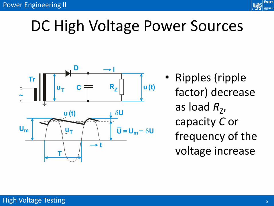
DC High Voltage Power Sources
• Ripples (ripple factor) decrease as load RZ, capacity C or frequency of the voltage increase
High Voltage Testing 6
Power Engineering II
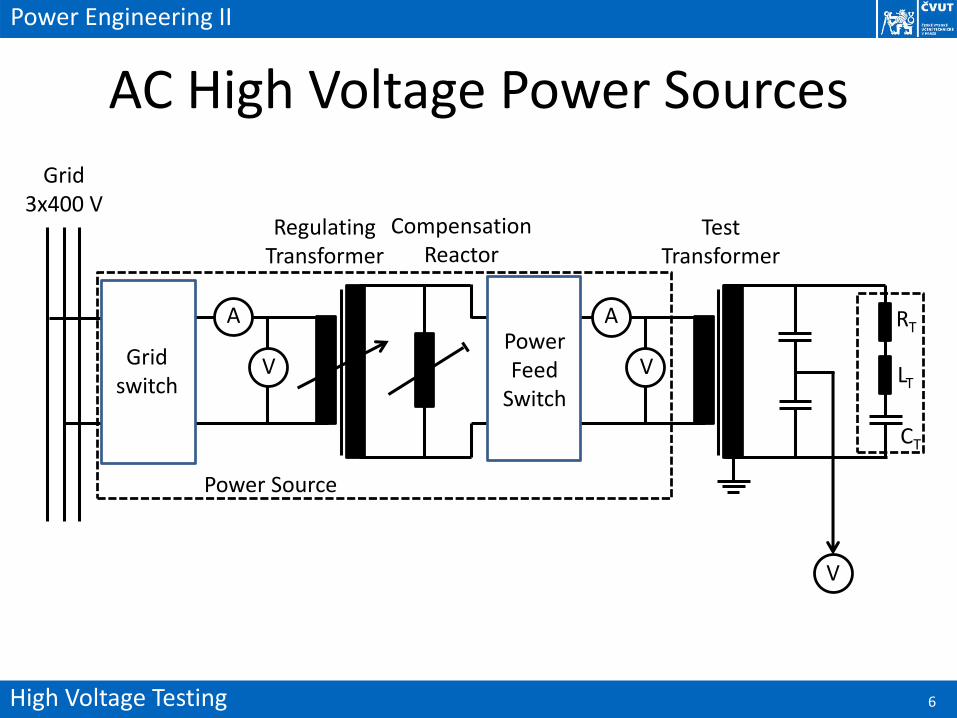
AC High Voltage Power Sources
Grid switch
A
VPower Feed
Switch
A
V
RT
LT
CT
Grid 3x400 V
Test Transformer
Regulating Transformer
Compensation Reactor
Power Source
V
High Voltage Testing 7
Power Engineering II
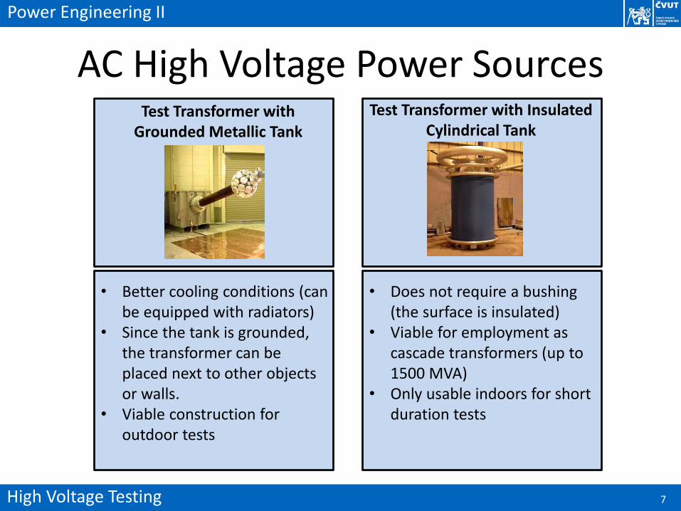
AC High Voltage Power Sources
• Better cooling conditions (can be equipped with radiators)
• Since the tank is grounded, the transformer can be placed next to other objects or walls.
• Viable construction for outdoor tests
• Does not require a bushing (the surface is insulated)
• Viable for employment as cascade transformers (up to 1500 MVA)
• Only usable indoors for short duration tests
Test Transformer with Insulated Cylindrical Tank
Test Transformer with Grounded Metallic Tank
High Voltage Testing 8
Power Engineering II
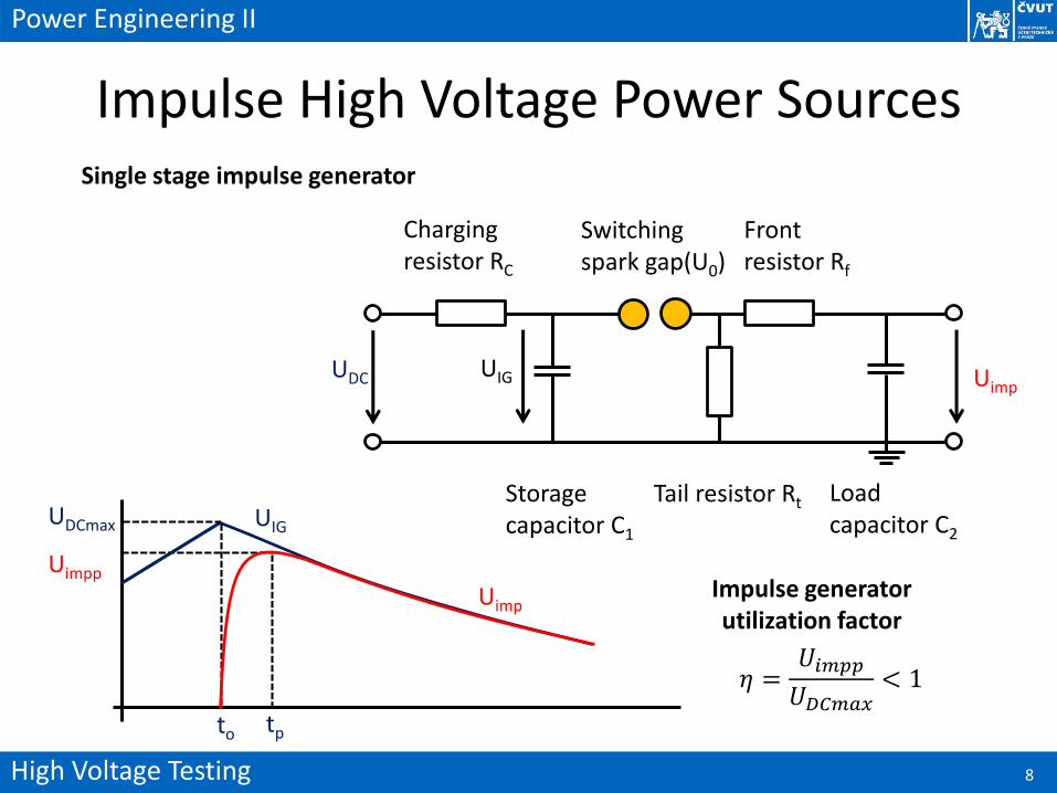
Impulse High Voltage Power SourcesSingle stage impulse generator
UDC UIG Uimp
Charging resistor RC
Switching spark gap(U0)
Front resistor Rf
Tail resistor RtStorage capacitor C1
Load capacitor C2
UDCmax
Uimpp
Uimp
UIG
to tp
Impulse generator utilization factor
𝜂 =𝑈𝑖𝑚𝑝𝑝
𝑈𝐷𝐶𝑚𝑎𝑥< 1
High Voltage Testing 9
Power Engineering II
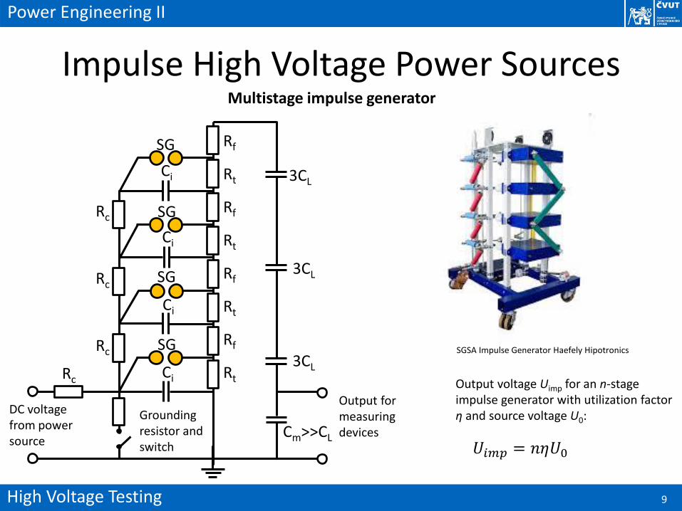
Impulse High Voltage Power SourcesMultistage impulse generator
SG
SG
SG
SG
Ci
Ci
Ci
CiRc
Rf
Rt
Rf
Rt
Rf
Rt
Rf
Rt
Rc
Rc
Rc
3CL
3CL
3CL
Cm>>CL
Output for measuring devices
Grounding resistor and switch
DC voltage from power source
SGSA Impulse Generator Haefely Hipotronics
𝑈𝑖𝑚𝑝 = 𝑛𝜂𝑈0
Output voltage Uimp for an n-stage impulse generator with utilization factor η and source voltage U0:
High Voltage Testing 10
Power Engineering II
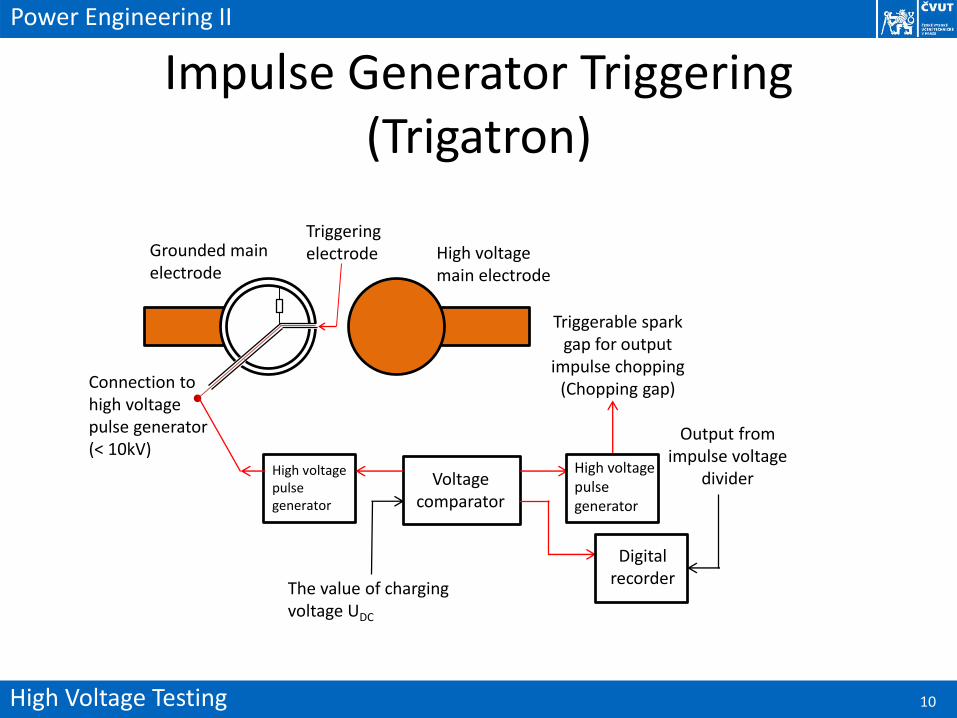
Impulse Generator Triggering (Trigatron)
High voltage main electrode
Grounded main electrode
Triggering electrode
Connection to high voltage pulse generator (< 10kV)
High voltage pulse generator
Voltage comparator
The value of charging voltage UDC
Triggerable spark gap for output
impulse chopping (Chopping gap)
High voltage pulse generator
Digital recorder
Output from impulse voltage
divider
High Voltage Testing 11
Power Engineering II
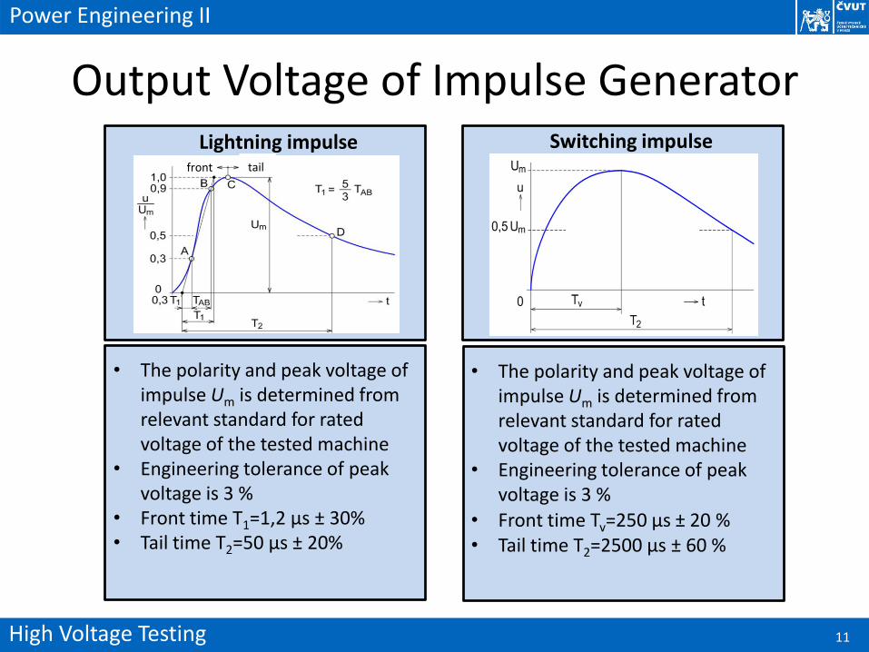
Output Voltage of Impulse Generator
• The polarity and peak voltage of impulse Um is determined from relevant standard for rated voltage of the tested machine
• Engineering tolerance of peak voltage is 3 %
• Front time T1=1,2 µs ± 30%• Tail time T2=50 µs ± 20%
• The polarity and peak voltage of impulse Um is determined from relevant standard for rated voltage of the tested machine
• Engineering tolerance of peak voltage is 3 %
• Front time Tv=250 µs ± 20 %• Tail time T2=2500 µs ± 60 %
Switching impulseLightning impulsefront tail
High Voltage Testing 12
Power Engineering II
High Voltage Dividers
• Resistive, capacitive, inductive and combined high voltage dividers are used for high voltage measurements.
• Inductive dividers are primarily employed for calibration purposes as they are far too expensive for very high voltage measurements.
• The upper electrode of a divider is equipped with toroidal rings, which prevent generation of partial discharges.
• The current passing through the divider should be lower than 10 mA (from Ohm's law we can determine minimal resistance: 1 MΩ/10 kV)
High Voltage Testing 13
Power Engineering II
Capacitive High Voltage Dividers
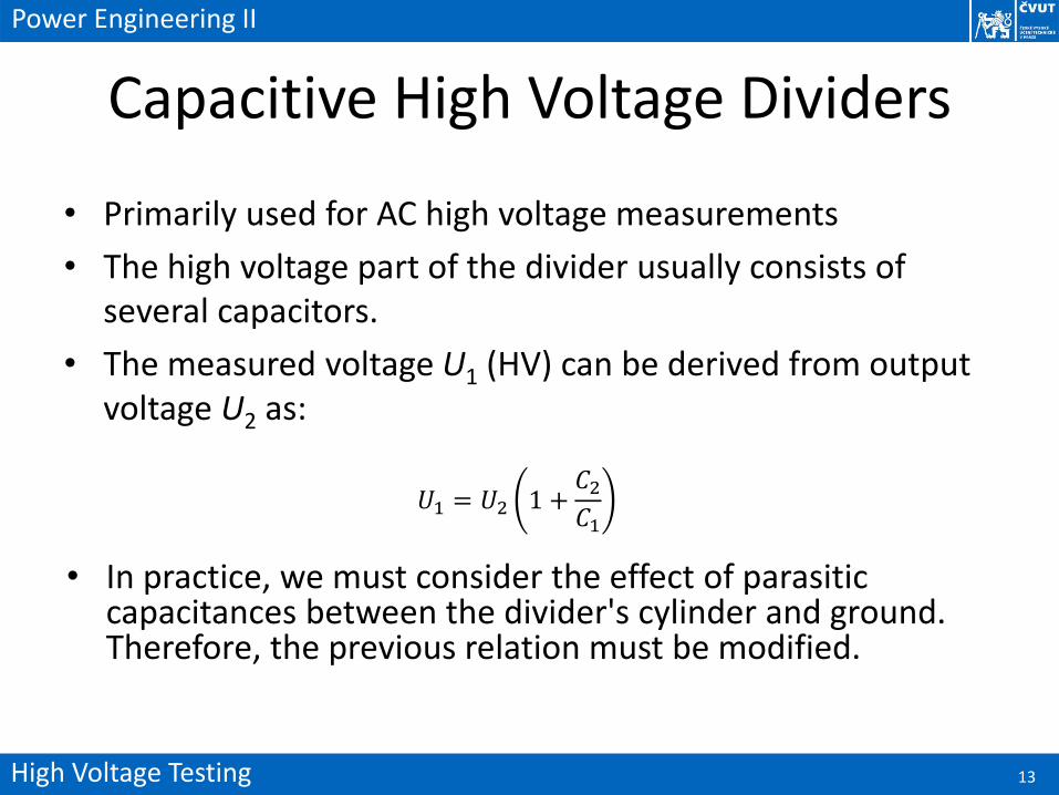
• Primarily used for AC high voltage measurements
• The high voltage part of the divider usually consists of several capacitors.
• The measured voltage U1 (HV) can be derived from output voltage U2 as:
𝑈1 = 𝑈2 1 +𝐶2𝐶1
• In practice, we must consider the effect of parasitic capacitances between the divider's cylinder and ground. Therefore, the previous relation must be modified.
C12
High Voltage Testing 14
Power Engineering II
Capacitive High Voltage Dividers
C11
C2Ce
d
Ie
I1
I2
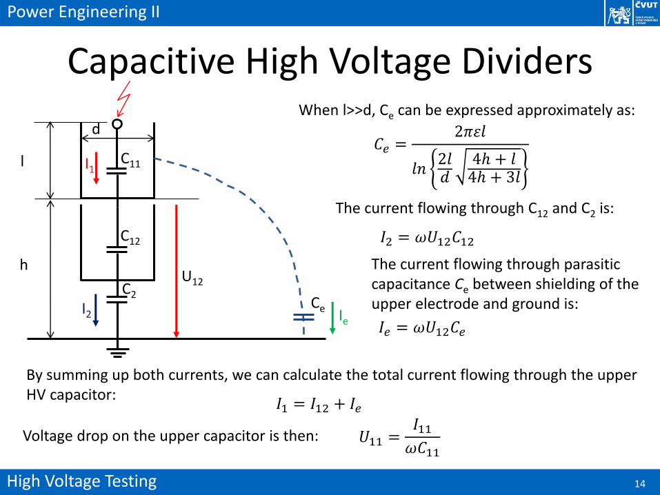
𝐶𝑒 =2𝜋휀𝑙
𝑙𝑛2𝑙𝑑
4ℎ + 𝑙4ℎ + 3𝑙
l
h
When l>>d, Ce can be expressed approximately as:
U12
𝐼2 = 𝜔𝑈12𝐶12
𝐼𝑒 = 𝜔𝑈12𝐶𝑒
𝐼1 = 𝐼12 + 𝐼𝑒
The current flowing through C12 and C2 is:
The current flowing through parasitic capacitance Ce between shielding of the upper electrode and ground is:
By summing up both currents, we can calculate the total current flowing through the upper HV capacitor:
Voltage drop on the upper capacitor is then: 𝑈11 =𝐼11𝜔𝐶11
High Voltage Testing 15
Power Engineering II
Capacitive High Voltage Dividers
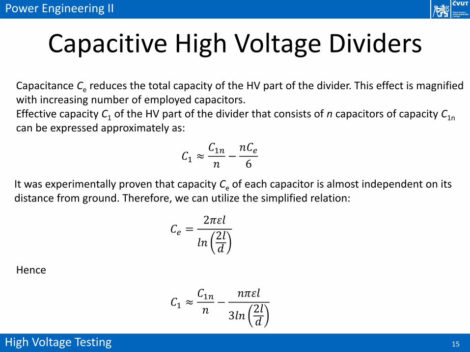
Capacitance Ce reduces the total capacity of the HV part of the divider. This effect is magnified with increasing number of employed capacitors.Effective capacity C1 of the HV part of the divider that consists of n capacitors of capacity C1n
can be expressed approximately as:
𝐶1 ≈𝐶1𝑛𝑛
−𝑛𝐶𝑒6
It was experimentally proven that capacity Ce of each capacitor is almost independent on its distance from ground. Therefore, we can utilize the simplified relation:
𝐶𝑒 =2𝜋휀𝑙
𝑙𝑛2𝑙𝑑
Hence
𝐶1 ≈𝐶1𝑛𝑛
−𝑛𝜋휀𝑙
3𝑙𝑛2𝑙𝑑
High Voltage Testing 16
Power Engineering II
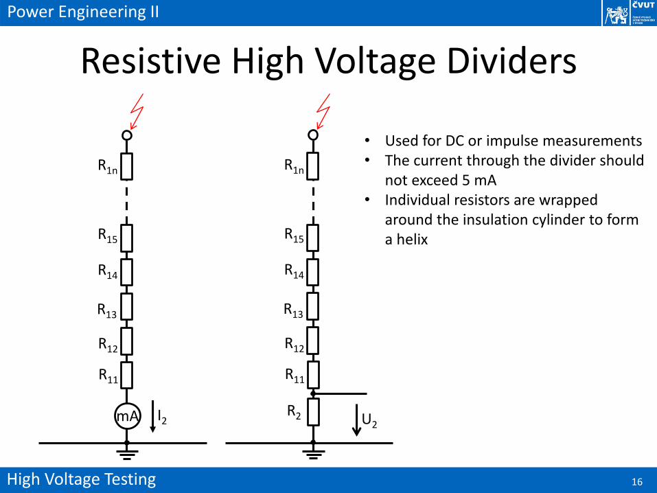
Resistive High Voltage Dividers
R12
R15
R1n
R14
R13
R11
mA
R12
R15
R1n
R14
R13
R11
I2 U2R2
• Used for DC or impulse measurements • The current through the divider should
not exceed 5 mA• Individual resistors are wrapped
around the insulation cylinder to form a helix
High Voltage Testing 17
Power Engineering II
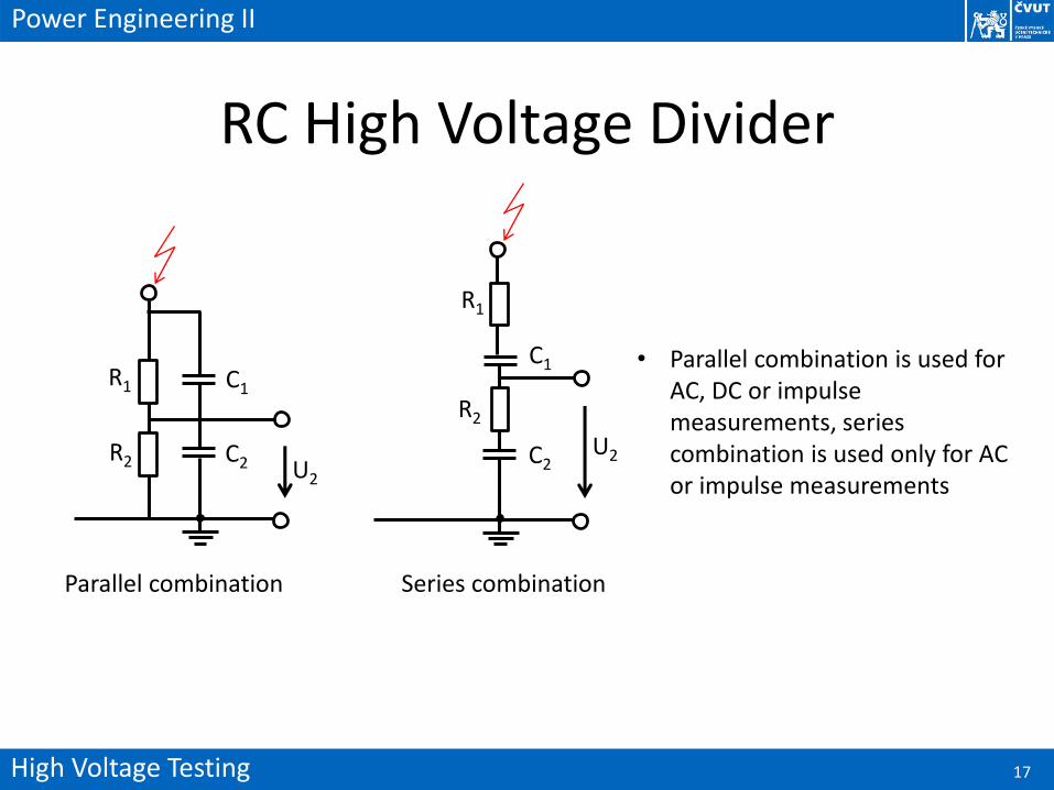
RC High Voltage Divider
U2
R1
R2
C1
C2U2
R1
R2
C1
C2
Parallel combination Series combination
• Parallel combination is used for AC, DC or impulse measurements, series combination is used only for AC or impulse measurements
High Voltage Testing 18
Power Engineering II
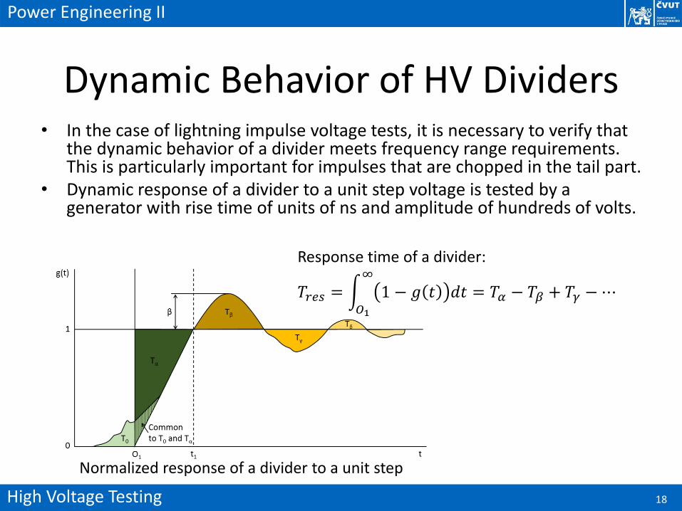
Dynamic Behavior of HV Dividers• In the case of lightning impulse voltage tests, it is necessary to verify that
the dynamic behavior of a divider meets frequency range requirements. This is particularly important for impulses that are chopped in the tail part.
• Dynamic response of a divider to a unit step voltage is tested by a generator with rise time of units of ns and amplitude of hundreds of volts.
Normalized response of a divider to a unit step
𝑇𝑟𝑒𝑠 = න𝑂1
∞
1 − 𝑔 𝑡 𝑑𝑡 = 𝑇𝛼 − 𝑇𝛽 + 𝑇𝛾 −⋯
Response time of a divider:
High Voltage Testing 19
Power Engineering II
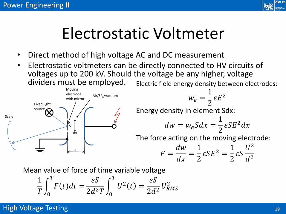
Electrostatic Voltmeter• Direct method of high voltage AC and DC measurement• Electrostatic voltmeters can be directly connected to HV circuits of
voltages up to 200 kV. Should the voltage be any higher, voltage dividers must be employed.
Air/SF6/vacuum
Moving electrode with mirror
Fixed light source
Scale
Electric field energy density between electrodes:
𝑤𝑒 =1
2휀𝐸2
Energy density in element Sdx:
𝑑𝑤 = 𝑤𝑒𝑆𝑑𝑥 =1
2휀𝑆𝐸2𝑑𝑥
The force acting on the moving electrode:
𝐹 =𝑑𝑤
𝑑𝑥=1
2휀𝑆𝐸2 =
1
2휀𝑆𝑈2
𝑑2
Mean value of force of time variable voltage
1
𝑇න0
𝑇
𝐹 𝑡 𝑑𝑡 =휀𝑆
2𝑑2𝑇න0
𝑇
𝑈2 𝑡 =휀𝑆
2𝑑2𝑈𝑅𝑀𝑆2
d
dx
S
High Voltage Testing 20
Power Engineering II
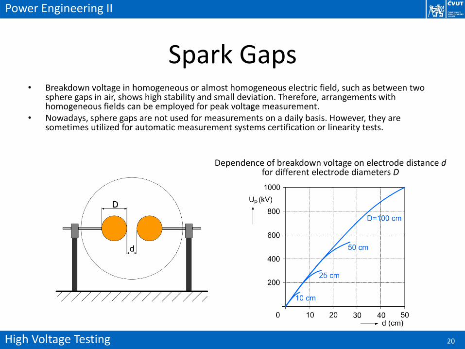
Spark Gaps• Breakdown voltage in homogeneous or almost homogeneous electric field, such as between two
sphere gaps in air, shows high stability and small deviation. Therefore, arrangements with homogeneous fields can be employed for peak voltage measurement.
• Nowadays, sphere gaps are not used for measurements on a daily basis. However, they are sometimes utilized for automatic measurement systems certification or linearity tests.
Dependence of breakdown voltage on electrode distance dfor different electrode diameters D
High Voltage Testing 21
Power Engineering II
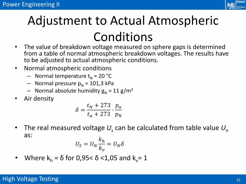
Adjustment to Actual Atmospheric Conditions
• The value of breakdown voltage measured on sphere gaps is determined from a table of normal atmospheric breakdown voltages. The results have to be adjusted to actual atmospheric conditions.
• Normal atmospheric conditions– Normal temperature tN = 20 °C– Normal pressure pN = 101,3 kPa– Normal absolute humidity gN = 11 g/m3
• Air density
𝛿 =𝑡𝑁 + 273
𝑡𝑎 + 273∙𝑝𝑎𝑝𝑁
• The real measured voltage Us can be calculated from table value Unas:
𝑈𝑆 = 𝑈𝑁𝑘ℎ𝑘𝑣
= 𝑈𝑁𝛿
• Where kh = δ for 0,95< δ <1,05 and kv= 1
High Voltage Testing 22
Power Engineering II
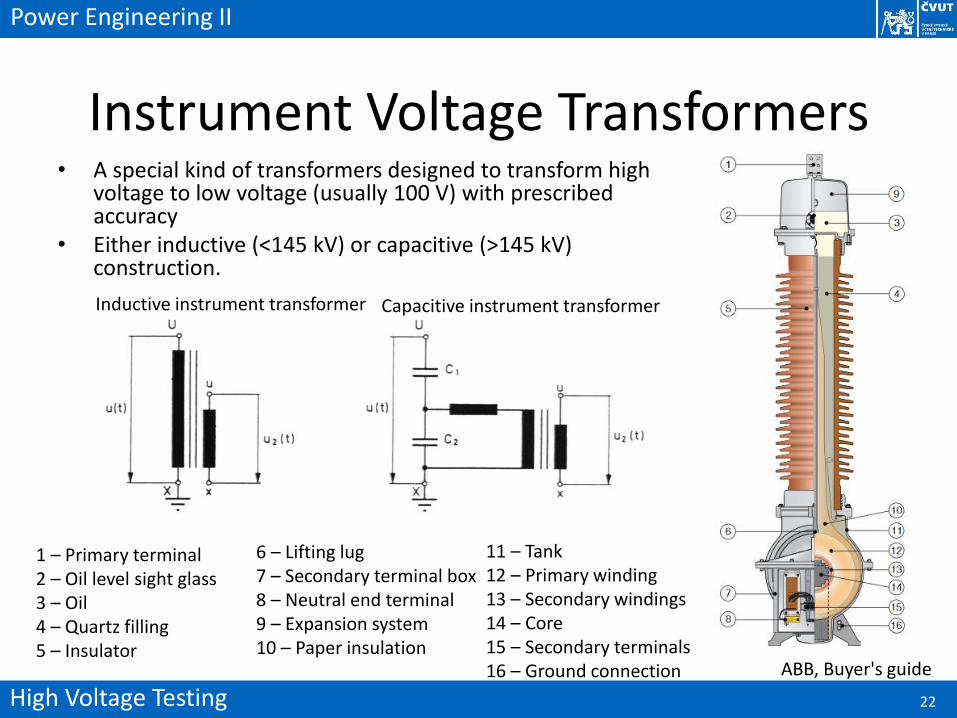
Instrument Voltage Transformers• A special kind of transformers designed to transform high
voltage to low voltage (usually 100 V) with prescribedaccuracy
• Either inductive (<145 kV) or capacitive (>145 kV) construction.
Inductive instrument transformer Capacitive instrument transformer
ABB, Buyer's guide
1 – Primary terminal2 – Oil level sight glass3 – Oil4 – Quartz filling5 – Insulator
11 – Tank12 – Primary winding13 – Secondary windings14 – Core15 – Secondary terminals16 – Ground connection
6 – Lifting lug7 – Secondary terminal box8 – Neutral end terminal9 – Expansion system10 – Paper insulation


![Code No: HIGH VOLTAGE ENGINEERING - padhle.com · impulse generator circuits. [7] 5 a) ... Explain about tripping and control of impulse generators. [7] 5 a) With neat sketch,](https://img.pdfslide.us/doc/110x75/5b55ff9d7f8b9ad9688c03ab/code-no-high-voltage-engineering-impulse-generator-circuits-7-5-a-.jpg)


![Micropower Impulse Radio [MIR] (U) - Defense Advanced ...archive.darpa.mil/sensit/PI_Briefs/Rosenbury_LLNL.pdf · Micropower Impulse Radio [MIR] (U) Tom Rosenbury, J. Hernandez, F](https://img.pdfslide.us/doc/110x75/5abbfe0a7f8b9a441d8d84b7/micropower-impulse-radio-mir-u-defense-advanced-impulse-radio-mir-u.jpg)