Embed Size (px)
Citation preview
High Tension Cable Barrier (HTCB): The Next Generation of Highway Safety
Author:
Nusrat Ahmad, P. Eng., Transportation Engineer
Morrison Hershfield
Co-Author:
Bruce Biglow, P. Eng., Director of Transportation/Roads and Highways West
Morrison Hershfield
Paper prepared for presentation
at the General Issues in Road Safety Session
of the 2019 TAC-ITS Canada Joint Conference, Halifax, NS
High Tension Cable Barrier (HTCB): The Next Generation of Highway Safety
1
Table of Contents
1. Abstract ................................................................................................................................................. 3
2. What is High Tension Cable Barrier (HTCB) and How Does it Work? ................................................... 3
2.1 Alberta Transportation Approved HTCB Products ........................................................................ 5
2.2 Advantages of HTCB over Traditional Guardrail ........................................................................... 6
2.2.1 Operational and Maintenance Considerations ..................................................................... 6
2.2.2 Safety .................................................................................................................................... 6
2.2.3 Cost ....................................................................................................................................... 6
2.1 When Not to Use HTCB ................................................................................................................. 6
2.2 Factors in Determining How to Implement HTCB ......................................................................... 7
2.2.1 Length of HTCB ...................................................................................................................... 7
2.2.2 Horizontal and Vertical Geometry ........................................................................................ 7
2.2.3 Cross-Section ......................................................................................................................... 7
2.2.4 Connections to Strong Post W-Beam Guardrail .................................................................. 12
2.2.5 Connections to Bridgerail .................................................................................................... 14
3. The Project .......................................................................................................................................... 14
3.1 Traffic and Safety ........................................................................................................................ 14
4. The Design Process ............................................................................................................................. 17
4.1 Existing Horizontal Alignment ..................................................................................................... 17
4.2 Existing Vertical Alignment ......................................................................................................... 17
4.3 Existing Cross-Section ................................................................................................................. 17
4.4 Strong Post W-beam Guardrail ................................................................................................... 18
4.4.1 Highway 60 Interchange ..................................................................................................... 18
4.4.2 CNR Overpass ...................................................................................................................... 18
4.4.3 Range Road 261 .................................................................................................................. 18
5. Challenges ........................................................................................................................................... 18
5.1 Challenges during Design ............................................................................................................ 18
5.1.1 Design Using Proprietary Systems ...................................................................................... 18
5.1.2 Guardrail and Bridgerail Connections ................................................................................. 19
5.1.3 Deflection Distance ............................................................................................................. 19
5.2 Challenges during Construction .................................................................................................. 19
5.2.1 Traffic Constraints ............................................................................................................... 19
High Tension Cable Barrier (HTCB): The Next Generation of Highway Safety
2
5.2.2 New Contractor ................................................................................................................... 20
5.2.3 Product Differences between Design and Construction ..................................................... 20
5.2.4 Issues during Installation .................................................................................................... 20
6. Conclusion ........................................................................................................................................... 20
7. References .......................................................................................................................................... 21
High Tension Cable Barrier (HTCB): The Next Generation of Highway Safety
3
1. Abstract
As more jurisdictions look for innovative ways and products to enhance median and roadside safety, High Tension Cable Barrier (HTCB) stands out as the latest product that delivers on safety, cost, and ease of maintenance. HTCB is unique in that it can accommodate hits from either side, making it an attractive choice for transportation agencies in order to reduce cross-median collisions and collision severity. Highway agencies and designers are tasked with the challenges of learning how to implement HTCB appropriately, both alone and in conjunction with traditional guardrail. This paper examines the particular case of Highway 16A in the Province of Alberta and how HTCB was implemented in a 10 km section to not only reduce collision frequencies and severity, but also how a relatively new and proprietary product was implemented. The paper discusses how horizontal and vertical geometry, cross-section, connections to existing bridgerail, and length of need all played their respective roles in determining the length and location of HTCB.
Highway 16A is a busy commuter highway, a remnant of the previous Trans-Canada Highway between Edmonton and Jasper. It now serves the cities of Spruce Grove and Edmonton and carries over 30,000 vehicles a day. The highway is 4-lane divided with a very narrow depressed median and no existing barriers of any kind. As a result, Highway 16A experienced a large number of cross-median collisions. Alberta Transportation (AT) sought to install HTCB as a way to reduce these collisions while allowing for ease of maintenance operations within the narrow median. Designers at Morrison Hershfield (MH), while familiar with traditional roadside barrier systems, conducted research on how to implement HTCB using AT’s Design Bulletin #75/2012 and HTCB (and Rumble Strips) Practices & Guidelines presentation.
The design had to consider many factors, such as horizontal and vertical geometry of each carriageway, superelevation, grade differences across the median, accommodating left-turn storage lanes, median openings and connections to existing bridgerail and strong-post W-beam. Construction had its own unique challenges, working with a contractor who was relatively new to HTCB, and AT’s requirements for working on a very busy highway, as well as the learning curve associated with installing a proprietary product.
Overall, the HTCB installation went smoothly as AT’s Project Manager, the designers, and contractor all worked together to complete the project. The finished project is a 10 km section of highway with new HTCB that is aesthetically compatible and provides a higher level of safety than before.
2. What is High Tension Cable Barrier (HTCB) and How Does it Work?
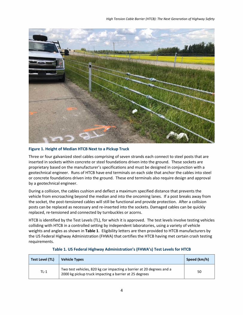
Prior to the implementation of HTCB, cable barrier systems typically had nominal tension to keep the cables in place and not sag along the run. They had a lower mounting height than HTCB with tighter spacing of cables resulting in a greater chance of the system not properly engaging an errant vehicle. They also had no option to add a fourth cable to further expand the ability to engage a broader range of vehicle size and orientation. These cable barrier systems required many anchor blocks compared to HTCB, especially along horizontal curves. They used wooden posts and offered protection only one one side of the system. HTCB on the other hand, uses pre-stretched, post tensioned cables mounted at a standardized height, closer to the height of a passenger vehicle and can be engaged on either side (refer to Figure 1).
High Tension Cable Barrier (HTCB): The Next Generation of Highway Safety
4
Figure 1. Height of Median HTCB Next to a Pickup Truck
Three or four galvanized steel cables comprising of seven strands each connect to steel posts that are inserted in sockets within concrete or steel foundations driven into the ground. These sockets are proprietary based on the manufacturer’s specifications and must be designed in conjunction with a geotechnical engineer. Runs of HTCB have end terminals on each side that anchor the cables into steel or concrete foundations driven into the ground. These end terminals also require design and approval by a geotechnical engineer.
During a collision, the cables cushion and deflect a maximum specified distance that prevents the vehicle from encroaching beyond the median and into the oncoming lanes. If a post breaks away from the socket, the post-tensioned cables will still be functional and provide protection. After a collision posts can be replaced as necessary and re-inserted into the sockets. Damaged cables can be quickly replaced, re-tensioned and connected by turnbuckles or acorns.
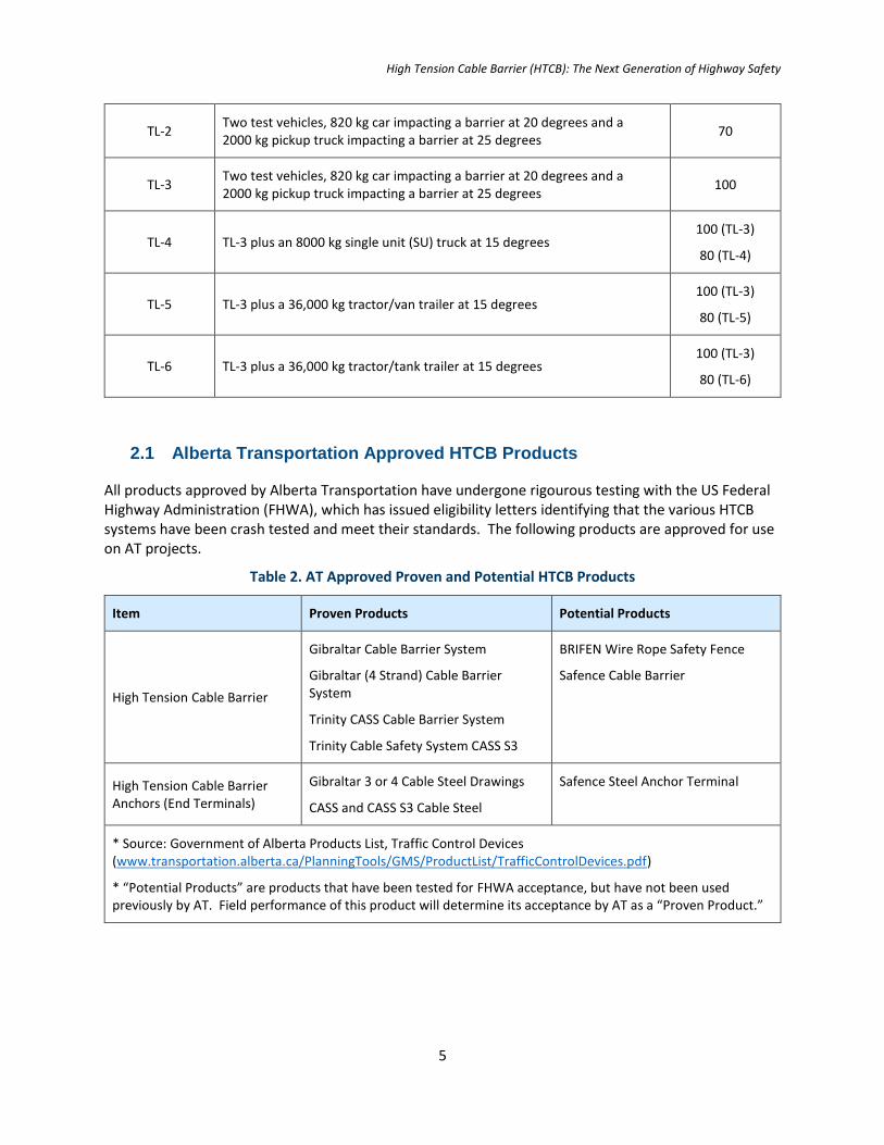
HTCB is identified by the Test Levels (TL), for which it is approved. The test levels involve testing vehicles colliding with HTCB in a controlled setting by independent laboratories, using a variety of vehicle weights and angles as shown in Table 1. Eligibility letters are then provided to HTCB manufacturers by the US Federal Highway Administration (FHWA) that certifies the HTCB having met certain crash testing requirements.
Table 1. US Federal Highway Administration’s (FHWA’s) Test Levels for HTCB
Test Level (TL) Vehicle Types Speed (km/h)
TL-1 Two test vehicles, 820 kg car impacting a barrier at 20 degrees and a 2000 kg pickup truck impacting a barrier at 25 degrees
50
High Tension Cable Barrier (HTCB): The Next Generation of Highway Safety
5
TL-2 Two test vehicles, 820 kg car impacting a barrier at 20 degrees and a 2000 kg pickup truck impacting a barrier at 25 degrees
70
TL-3 Two test vehicles, 820 kg car impacting a barrier at 20 degrees and a 2000 kg pickup truck impacting a barrier at 25 degrees
100
TL-4 TL-3 plus an 8000 kg single unit (SU) truck at 15 degrees 100 (TL-3)
80 (TL-4)
TL-5 TL-3 plus a 36,000 kg tractor/van trailer at 15 degrees 100 (TL-3)
80 (TL-5)
TL-6 TL-3 plus a 36,000 kg tractor/tank trailer at 15 degrees 100 (TL-3)
80 (TL-6)
2.1 Alberta Transportation Approved HTCB Products
All products approved by Alberta Transportation have undergone rigourous testing with the US Federal Highway Administration (FHWA), which has issued eligibility letters identifying that the various HTCB systems have been crash tested and meet their standards. The following products are approved for use on AT projects.
Table 2. AT Approved Proven and Potential HTCB Products
Item Proven Products Potential Products
High Tension Cable Barrier
Gibraltar Cable Barrier System
Gibraltar (4 Strand) Cable Barrier System
Trinity CASS Cable Barrier System
Trinity Cable Safety System CASS S3
BRIFEN Wire Rope Safety Fence
Safence Cable Barrier
High Tension Cable Barrier Anchors (End Terminals)
Gibraltar 3 or 4 Cable Steel Drawings
CASS and CASS S3 Cable Steel
Safence Steel Anchor Terminal
* Source: Government of Alberta Products List, Traffic Control Devices (www.transportation.alberta.ca/PlanningTools/GMS/ProductList/TrafficControlDevices.pdf)
* “Potential Products” are products that have been tested for FHWA acceptance, but have not been used previously by AT. Field performance of this product will determine its acceptance by AT as a “Proven Product.”
High Tension Cable Barrier (HTCB): The Next Generation of Highway Safety
6
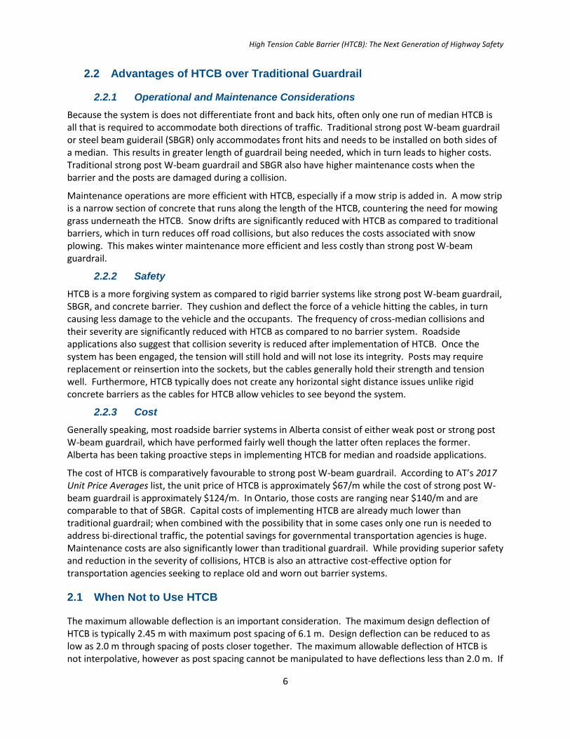
2.2 Advantages of HTCB over Traditional Guardrail
2.2.1 Operational and Maintenance Considerations
Because the system is does not differentiate front and back hits, often only one run of median HTCB is all that is required to accommodate both directions of traffic. Traditional strong post W-beam guardrail or steel beam guiderail (SBGR) only accommodates front hits and needs to be installed on both sides of a median. This results in greater length of guardrail being needed, which in turn leads to higher costs. Traditional strong post W-beam guardrail and SBGR also have higher maintenance costs when the barrier and the posts are damaged during a collision.
Maintenance operations are more efficient with HTCB, especially if a mow strip is added in. A mow strip is a narrow section of concrete that runs along the length of the HTCB, countering the need for mowing grass underneath the HTCB. Snow drifts are significantly reduced with HTCB as compared to traditional barriers, which in turn reduces off road collisions, but also reduces the costs associated with snow plowing. This makes winter maintenance more efficient and less costly than strong post W-beam guardrail.
2.2.2 Safety
HTCB is a more forgiving system as compared to rigid barrier systems like strong post W-beam guardrail, SBGR, and concrete barrier. They cushion and deflect the force of a vehicle hitting the cables, in turn causing less damage to the vehicle and the occupants. The frequency of cross-median collisions and their severity are significantly reduced with HTCB as compared to no barrier system. Roadside applications also suggest that collision severity is reduced after implementation of HTCB. Once the system has been engaged, the tension will still hold and will not lose its integrity. Posts may require replacement or reinsertion into the sockets, but the cables generally hold their strength and tension well. Furthermore, HTCB typically does not create any horizontal sight distance issues unlike rigid concrete barriers as the cables for HTCB allow vehicles to see beyond the system.
2.2.3 Cost
Generally speaking, most roadside barrier systems in Alberta consist of either weak post or strong post W-beam guardrail, which have performed fairly well though the latter often replaces the former. Alberta has been taking proactive steps in implementing HTCB for median and roadside applications.
The cost of HTCB is comparatively favourable to strong post W-beam guardrail. According to AT’s 2017 Unit Price Averages list, the unit price of HTCB is approximately $67/m while the cost of strong post W-beam guardrail is approximately $124/m. In Ontario, those costs are ranging near $140/m and are comparable to that of SBGR. Capital costs of implementing HTCB are already much lower than traditional guardrail; when combined with the possibility that in some cases only one run is needed to address bi-directional traffic, the potential savings for governmental transportation agencies is huge. Maintenance costs are also significantly lower than traditional guardrail. While providing superior safety and reduction in the severity of collisions, HTCB is also an attractive cost-effective option for transportation agencies seeking to replace old and worn out barrier systems.
2.1 When Not to Use HTCB
The maximum allowable deflection is an important consideration. The maximum design deflection of HTCB is typically 2.45 m with maximum post spacing of 6.1 m. Design deflection can be reduced to as low as 2.0 m through spacing of posts closer together. The maximum allowable deflection of HTCB is not interpolative, however as post spacing cannot be manipulated to have deflections less than 2.0 m. If
High Tension Cable Barrier (HTCB): The Next Generation of Highway Safety
7
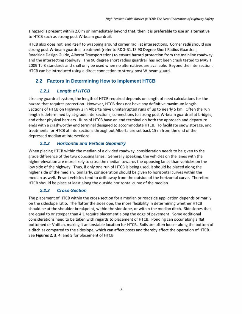
a hazard is present within 2.0 m or immediately beyond that, then it is preferable to use an alternative to HTCB such as strong post W-beam guardrail.
HTCB also does not lend itself to wrapping around corner radii at intersections. Corner radii should use strong post W-beam guardrail treatment (refer to RDG-B1.13 90 Degree Short Radius Guardrail, Roadside Design Guide, Alberta Transportation) to ensure hazard protection from the mainline roadway and the intersecting roadway. The 90 degree short radius guardrail has not been crash tested to MASH 2009 TL-3 standards and shall only be used when no alternatives are available. Beyond the intersection, HTCB can be introduced using a direct connection to strong post W-beam guard.
2.2 Factors in Determining How to Implement HTCB
2.2.1 Length of HTCB
Like any guardrail system, the length of HTCB required depends on length of need calculations for the hazard that requires protection. However, HTCB does not have any definitive maximum length. Sections of HTCB on Highway 2 in Alberta have uninterrupted runs of up to nearly 5 km. Often the run length is determined by at-grade intersections, connections to strong post W-beam guardrail at bridges, and other physical barriers. Runs of HTCB have an end terminal on both the approach and departure ends with a crashworthy end terminal designed to accommodate HTCB. To facilitate snow storage, end treatments for HTCB at intersections throughout Alberta are set back 15 m from the end of the depressed median at intersections.
2.2.2 Horizontal and Vertical Geometry
When placing HTCB within the median of a divided roadway, consideration needs to be given to the grade difference of the two opposing lanes. Generally speaking, the vehicles on the lanes with the higher elevation are more likely to cross the median towards the opposing lanes than vehicles on the low side of the highway. Thus, if only one run of HTCB is being used, it should be placed along the higher side of the median. Similarly, consideration should be given to horizontal curves within the median as well. Errant vehicles tend to drift away from the outside of the horizontal curve. Therefore HTCB should be place at least along the outside horizontal curve of the median.
2.2.3 Cross-Section
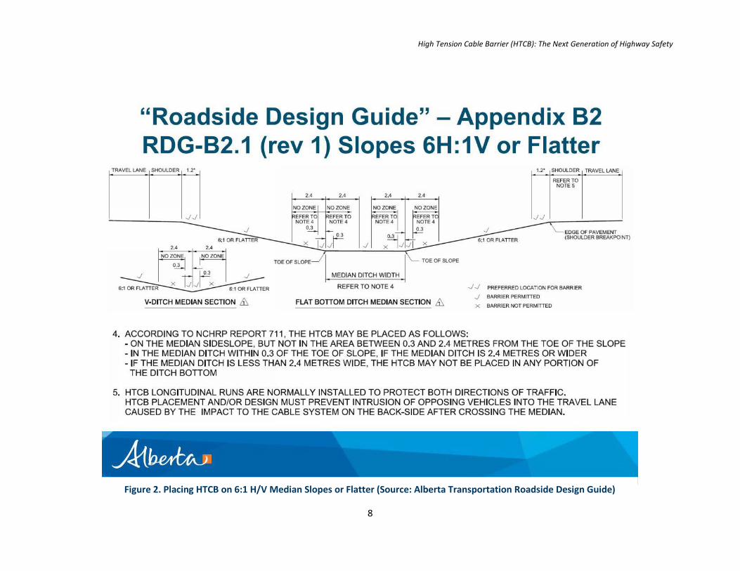
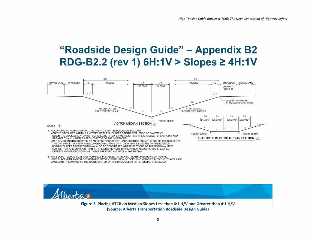
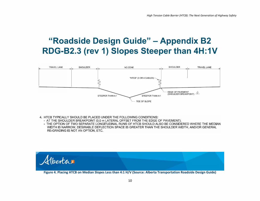
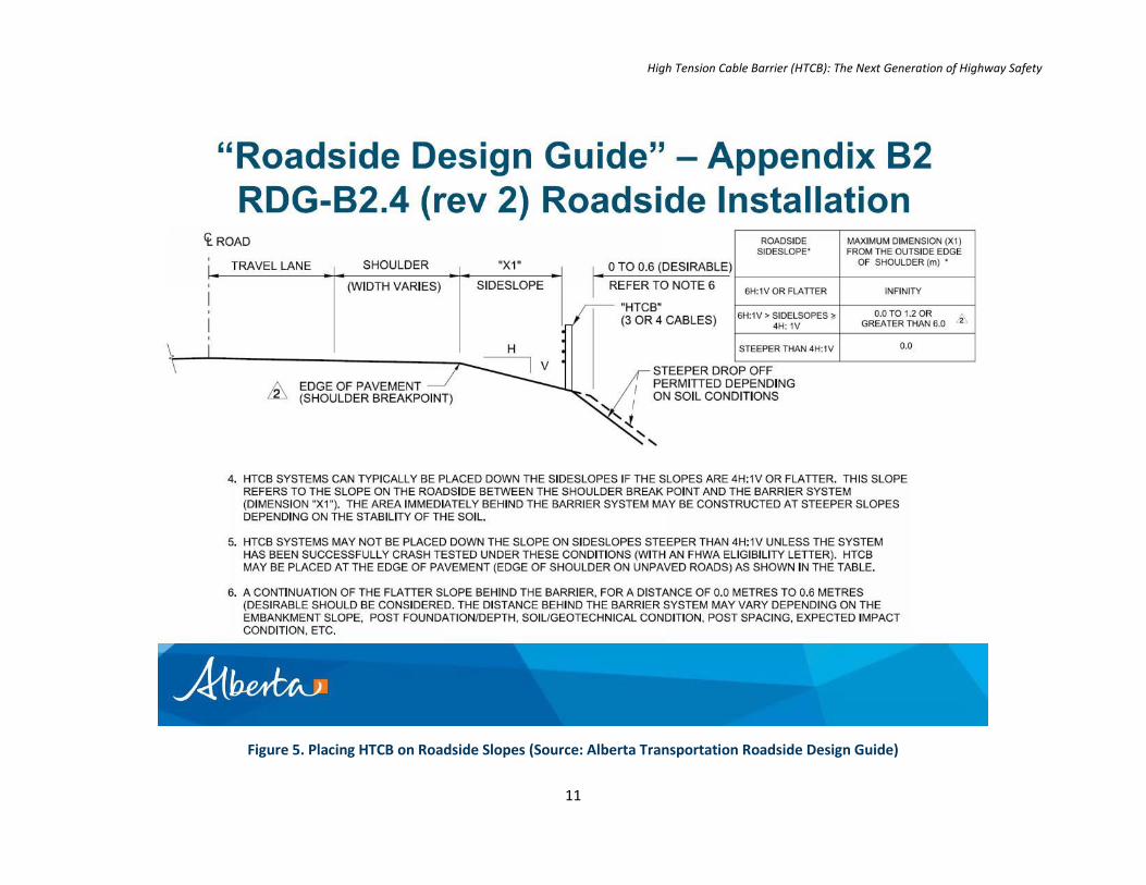
The placement of HTCB within the cross-section for a median or roadside application depends primarily on the sideslope ratio. The flatter the sideslope, the more flexibility in determining whether HTCB should be at the shoulder breakpoint, within the sideslope, or within the median ditch. Sideslopes that are equal to or steeper than 4:1 require placement along the edge of pavement. Some additional considerations need to be taken with regards to placement of HTCB. Ponding can occur along a flat bottomed or V-ditch, making it an unstable location for HTCB. Soils are often looser along the bottom of a ditch as compared to the sideslope, which can affect posts and thereby affect the operation of HTCB. See Figures 2, 3, 4, and 5 for placement of HTCB.
High Tension Cable Barrier (HTCB): The Next Generation of Highway Safety
8
Figure 2. Placing HTCB on 6:1 H/V Median Slopes or Flatter (Source: Alberta Transportation Roadside Design Guide)
High Tension Cable Barrier (HTCB): The Next Generation of Highway Safety
9
Figure 3. Placing HTCB on Median Slopes Less than 6:1 H/V and Greater than 4:1 H/V (Source: Alberta Transportation Roadside Design Guide)
High Tension Cable Barrier (HTCB): The Next Generation of Highway Safety
10
Figure 4. Placing HTCB on Median Slopes Less than 4:1 H/V (Source: Alberta Transportation Roadside Design Guide)
High Tension Cable Barrier (HTCB): The Next Generation of Highway Safety
11
Figure 5. Placing HTCB on Roadside Slopes (Source: Alberta Transportation Roadside Design Guide)
High Tension Cable Barrier (HTCB): The Next Generation of Highway Safety
12
2.2.4 Connections to Strong Post W-Beam Guardrail
Connections between HTCB and strong post W-beam guardrail can be achieved through either a direct or indirect connection. A direct connection involves joining the HTCB and strong post W-beam guardrail and then immediately transitioning the guardrail to a flared end treatment. The flared end treatment is proprietary and usually not specified in AT contract documents.
Indirect connections involve running HTCB with strong post W-beam guardrail completely independent of each other, with either a full or partial overlap between the two systems. A full overlap involves existing guardrail running in parallel behind HTCB. The existing guardrail may be providing protection for a bridge pier or some other hazard that addresses only its length of need. Rather than providing a break in HTCB, the HTCB is run continuously before and after the hazard and adds a second layer of safety.
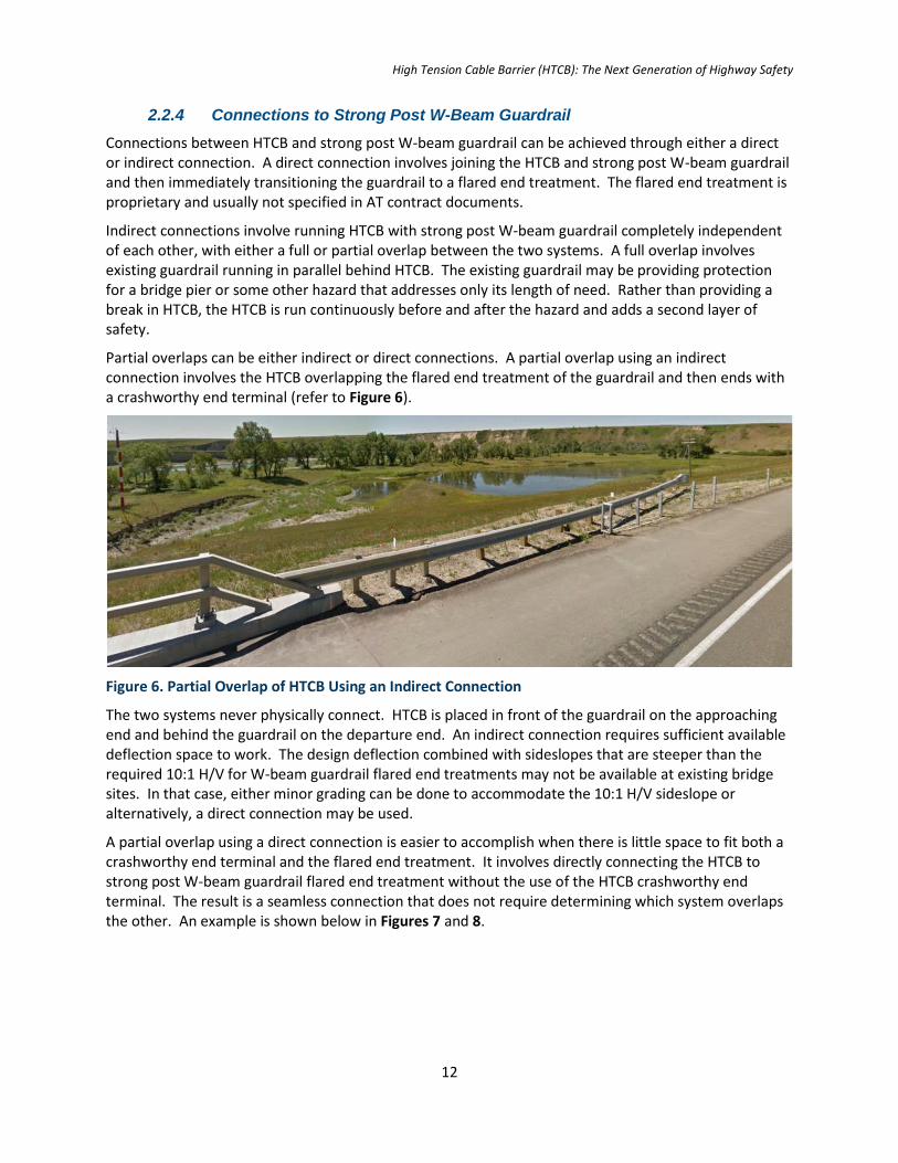
Partial overlaps can be either indirect or direct connections. A partial overlap using an indirect connection involves the HTCB overlapping the flared end treatment of the guardrail and then ends with a crashworthy end terminal (refer to Figure 6).
Figure 6. Partial Overlap of HTCB Using an Indirect Connection
The two systems never physically connect. HTCB is placed in front of the guardrail on the approaching end and behind the guardrail on the departure end. An indirect connection requires sufficient available deflection space to work. The design deflection combined with sideslopes that are steeper than the required 10:1 H/V for W-beam guardrail flared end treatments may not be available at existing bridge sites. In that case, either minor grading can be done to accommodate the 10:1 H/V sideslope or alternatively, a direct connection may be used.
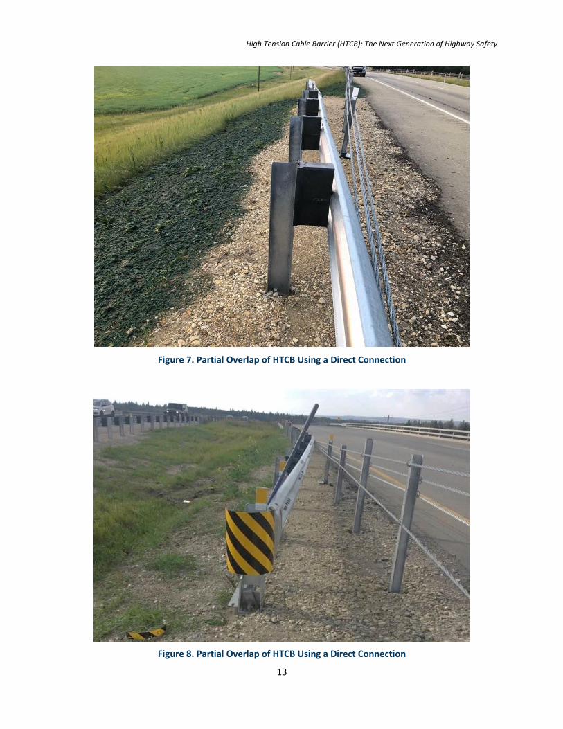
A partial overlap using a direct connection is easier to accomplish when there is little space to fit both a crashworthy end terminal and the flared end treatment. It involves directly connecting the HTCB to strong post W-beam guardrail flared end treatment without the use of the HTCB crashworthy end terminal. The result is a seamless connection that does not require determining which system overlaps the other. An example is shown below in Figures 7 and 8.
High Tension Cable Barrier (HTCB): The Next Generation of Highway Safety
13
Figure 7. Partial Overlap of HTCB Using a Direct Connection
Figure 8. Partial Overlap of HTCB Using a Direct Connection
High Tension Cable Barrier (HTCB): The Next Generation of Highway Safety
14
2.2.5 Connections to Bridgerail
Connections to bridgerail cannot be facilitated through a direct connection with HTCB. Instead, this is achieved with a connection of bridgerail to thrie beam, then from thrie beam to strong post W-beam, which then connects to HTCB either through a direct or indirect connection.
3. The Project
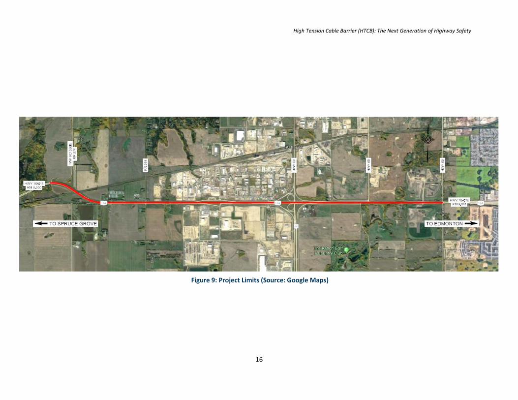
Morrison Hershfield was retained by Alberta Transportation to design HTCB along Highway 16A:16 from km 0.000 to 9.081 in order to improve safety and reduce the number of cross-median collisions. Roadside locations for HTCB were also examined at the following locations along Highway 16A:16:
The outside right shoulder from km 0.738 to km 1.179 at the Canadian National Railway (CNR) overpass
The outside left shoulder from km 0.630 to km 1.185 at the CNR overpass
The outside right shoulder from km 5.760 to km 5.843 at Highway 60 interchange
The outside left shoulder from km 5.808 to km 5.898 at Highway 60 interchange
The outside right shoulder from km 7.804 to km 7.952 and km 8.423 to km 8.541 between Range Road 262 and Edmonton city limits
The outside left shoulder from km 8.063 to km 8.229 and km 8.902 to 9.070 between Range Road 262 and Edmonton city limits
Highway 16A is a commuter highway, formerly part of the old Trans-Canada Highway 16, which serves the City of Edmonton and the City of Spruce Grove. The highway is an arterial roadway with a rural four lane cross-section with at-grade intersections dispersed throughout. It has a design speed of 110 km/h (posted speed of 100 km/h) with substandard vertical curvature as well as substandard shoulder and median widths, compared to current-day design guidelines. The median is a V-ditch that varies from 0.97 m to 3.45 m width. Median side shoulder widths range from 0.33 m to 3.54 m. Existing sideslopes range from 2.87:1 H/V to 19.44:1 H/V with many localized cross-sections having sideslopes steeper than 4:1 H/V.
At the east end of Highway 16A:16 is a Canadian National Railway (CNR) overpass that required a connection to existing bridgerail. The Highway 60 interchange is located approximately in the middle of the project limits and has existing weak post W-beam guardrail that needed to be upgraded.
Roadside barriers were needed at the CNR overpass, the Highway 60 bridge piers, and at spot locations to the west end of the project limits where roadside hazards were identified by AT, as noted previously.
3.1 Traffic and Safety
Highway 16A:16 has a weighted Annual Average Daily Traffic (WAADT) of over 31,000 vehicles a day with a growth rate of 1.5% and an existing level of service of ‘C.’ The five year total collision rate from 2010 to 2014 is 59.31 collisions per 100 million vehicle km per day, which is greater than the provincial average of 50.43 collisions per 100 million vehicle km per day.. Non-animal collision rate for the five year period between 2010 and 2014 is 49.56 collisions per 100 million vehicle km per day. For this approximately 9 km stretch of highway, the three most predominant collision types are rear end, off road left, and off road right collisions. The frequency and severity of off road collisions would be alleviated with the implementation of HTCB in both the median and roadside applications.
High Tension Cable Barrier (HTCB): The Next Generation of Highway Safety
15
Installation of HTCB would need to consider the high traffic volume of Highway 16A. One lane in each direction would need to be maintained during construction to prevent excessive disruption to traffic operations.
High Tension Cable Barrier (HTCB): The Next Generation of Highway Safety
16
Figure 9: Project Limits (Source: Google Maps)
High Tension Cable Barrier (HTCB): The Next Generation of Highway Safety
17
4. The Design Process
4.1 Existing Horizontal Alignment
Highway 16A:16 starts at west of Township Road 530B/Range Road 270 and heads east ending at Range Road 261. The majority of this section consists of a tangent alignment with R700 m and R865 m centerline radii at km 0.078 and km 1.67 respectively. These horizontal curves correspond with a 110 km/h design speed.
4.2 Existing Vertical Alignment
Most of the vertical curves along Highway 16A:16 meet the 110 km/h design speed except for two. Existing sag curves of K = 30 and K = 22 can be found at km 7.869 and km 8.892. These curves are below that of new construction standards of K sag 60 and also AT’s 3R/4R standards of K sag 31. Vertical curve reconstruction was not a part of the scope for the project and was therefore not considered.
The existing westbound lanes of Highway 16A:16 are generally at a higher elevation as compared to the existing eastbound lanes. The higher elevation of the westbound lanes indicate that HTCB will need to be installed along the westbound median sideslope at a minimum.
4.3 Existing Cross-Section
As part of the preliminary design process, MH identified the existing sideslopes along the median and selected roadside locations to determine where to place the HTCB within the sideslope. Existing sideslopes ranged from 2.87:1 H/V to 19.44:1 H/V, which were then categorized as the following:
Sideslopes that are 6:1 H/V or flatter;
Sideslopes ranging between 4:1 H/V and 6:1 H/V;
Sideslopes steeper than 4:1 H/V.
An overview plan was created to show the categorization of these sideslopes. It clearly showed steeper median sideslopes for the westbound lanes compared to the eastbound lanes. The overview plan shown on the next pages was developed during preliminary design.
One concern was the existing inside shoulder width of Highway 16A. Because the shoulder width was substandard, a back hit from the median into the proposed HTCB would deflect into the existing shoulder of the oncoming lane, possibly resulting in another collision. This could be alleviated by introducing two runs of HTCB (one in each direction) along the median.
However, MH did need to consider that despite having two runs of HTCB, the width of the existing median of Highway 16A, which is quite narrow along most of the project, as low as approximately 5 m at some locations. If one HTCB system is engaged from one direction, and a second simultaneous collision occurs at the same location and at the same time but from the opposite direction, the narrow median would not be able to accommodate the deflections of both systems. Through consultation with AT, MH reached the conclusion that while engaging HTCB from both sides at the same location and at the same time is possible, it is not probable. MH’s design for two runs for the westbound and eastbound sides of the median is conservative and the most reasonable engineering solution.
High Tension Cable Barrier (HTCB): The Next Generation of Highway Safety
18
4.4 Strong Post W-beam Guardrail
HTCB could not be used throughout the project as some locations and they are noted in the next few sections.
4.4.1 Highway 60 Interchange
The available deflection space was determined for both the roadside and median barrier systems. It was determined that the available deflection space between the edge of pavement (shoulder breakpoint) and the existing piers of the Highway 60 interchange was approximately 1.5 m, which is less than the 2.0 m minimum deflection required for HTCB to be operational. Strong post W-beam guardrail was used along the eastbound and westbound median sides with direct connections to HTCB beyond the length of need for the pier hazards.
4.4.2 CNR Overpass
As discussed in previous sections, HTCB cannot connect directly to bridgerail. The CNR overpass required a transition from HTCB to the existing bridgerail. MH designed a direct connection between HTCB and strong post W-beam guardrail, which then transitioned to thrie beam before connecting to the existing bridgerail. Designers opted to replace the old thrie beam with new, to provide a cohesive direct connection, but also an aesthetically pleasing one. Some minor re-grading of the sideslopes was needed to accommodate the flared end treatment of the W-beam guardrail.
4.4.3 Range Road 261
Roadside HTCB was to terminate at the east end of the project limits at the intersection of Highway 16A and Range Road 261 along its westerly corner radii. HTCB cannot accommodate small radii, therefore a decision was made to use strong post W-beam guardrail along the entire length of need for the roadside hazard over using a transition to HTCB. This provided consistent guardrail along the length of need for an otherwise short length of need of 192 m and produced a cost savings of not having to use connections to HTCB.
5. Challenges
5.1 Challenges during Design
5.1.1 Design Using Proprietary Systems
Several challenges were encountered during design. Designers at MH had designed HTCB in Ontario, however this was somewhat different to how it was to be implemented on Highway 16A. Designers used AT’s Design Bulletin 75/2012 and the Tri-Party Conference presentation to familiarize themselves with HTCB implementation in Alberta. Designers had to understand how the design deflection works using an example HTCB system. Drawings illustrating the Gibraltar system were used as reference to arrive at the final design. However, AT contract documents are not to identify which HTCB product to use. Rather, the contractor is free to decide which of the approved products to use and each product is proprietary. Minimum and maximum design deflections, post spacing, and the type of cables among other things are completely proprietary. Even though designers had used the Gibraltar system as a reference to develop the design, the Trinity product was selected by the contractor and installed on the project.
Traditional guardrail products are easier to design and do not change with proprietary systems as HTCB does. Also, because guardrail has been around for a long time, most designers are very familiar with
High Tension Cable Barrier (HTCB): The Next Generation of Highway Safety
19
how to apply it. HTCB, however, is a relatively new product in Canada that is unfamiliar for most engineers.
5.1.2 Guardrail and Bridgerail Connections
MH also had to learn how to connect HTCB to bridgerails and guardrails as part of the Highway 16A:16 assignment. Indirect connections require more space to accommodate both strong post W-beam guardrail and HTCB as well as their crashworthy end treatments. This is in contrast to direct connections where the HTCB directly connects to the functional crash tested portion of the strong post W-beam guardrail with the flared end treatment located immediately behind the HTCB. The overlap itself was challenging to determine, whether HTCB overlaps strong post W-beam guardrail or vice versa depending on the direction of traffic.
On Highway 16A, there was insufficient lateral space for the indirect connections, particularly at the CNR bridge which had steep roadway sideslopes. Those sideslopes would have required significant re-grading to fit the two systems.
5.1.3 Deflection Distance
One of the biggest misconceptions during design was that the design deflection was interpolative, that it could be reduced to below 2.0 m by merely spacing the posts closer together. However this assumption is not valid. HTCB is not appropriate for locations where less than 2.0 m of deflection space is available behind the system.
5.2 Challenges during Construction
5.2.1 Traffic Constraints
The biggest challenge during construction was accommodating the high traffic volume and the required lane closures to safely install the HTCB along the median and roadside edge of pavement (shoulder breakpoint) of Highway 16A:16. The contract documents stipulated that the contractor was not permitted to close any lanes on holiday weekends or the day preceding a holiday weekend. Furthermore, eastbound lane closures were not allowed:
From Monday through Friday from 6:00 am to 8:00 am,
From Monday through Thursday from 2:00 pm to 6:00 pm,
On Friday from 1:00 pm to 6:00 pm, and
On Saturday and Sunday from 11:00 am to 6:00 pm.
Westbound lane closures were not permitted:
From Monday through Thursday 3:00 pm to 7:00 pm,
On Friday 12:00 pm to 7:00 pm, and
On Saturday and Sunday from 12:00 pm to 5:00 pm.
The restrictions noted above impacted the number of working days and made estimation and adherence to contractual occupancy days a formidable task.
Moreover, two other projects were taking place during the same time along Highway 16A including one for the City of Edmonton that conflicted with the HTCB design by MH at the east end of the project. Some design changes needed to be made in the field to fit with the HTCB and guardrail design for the intersection reconstruction. The construction zones became concurrent, leading to a very long construction zone.
High Tension Cable Barrier (HTCB): The Next Generation of Highway Safety
20
5.2.2 New Contractor
Just as designers were new to HTCB, the lowest bid contractor was new to both AT highways work and HTCB. The contractor teamed up with their staff from Ontario who had worked with HTCB on Ontario projects to quickly enhance their knowledge of installing such a complex product. Their collaboration was successful as they were the only contractor in Alberta to install the connections between HTCB and strong post W-beam guardrail correctly the first time.
5.2.3 Product Differences between Design and Construction
Because HTCB is proprietary, it is difficult to design in any particular way. Designers need to make assumptions as to what possible product will be used and then incorporate that into the design. MH designers based their design on an HTCB product by Gibraltar. However, the contractor opted to use the Trinity product, which has different length end terminals. This affected the quantity of HTCB cable as the Trinity end terminals are longer than that of Gibraltar. Furthermore, the Trinity end terminals cost more than designers originally assumed for tender. This discrepancy affected the overall contract price. Future contracts will need to consider the exact type of HTCB being used in coming up with a bid price.
5.2.4 Issues during Installation
Installing HTCB had its challenges as it is not conducive to kinks or sharp curves in either the horizontal or vertical alignment. Horizontal curve radii for the edge of pavement differs slightly from that of the centerline of the highway. On this project in one location the edge of pavement radii on Highway 16A:16 were at the minimum specified radius for the Trinity HTCB, making posts staying in their proper location a difficult task when the cables were tensioned. In particular, the 700 m radius curve along the centerline of Highway 16A:16 has a smaller, tighter radius along the eastbound edge of pavement as construction crews struggled to install HTCB.
Along some sharp vertical curves, some of the posts would rise up from the sockets upon tensioning of the cables. The manufacturer recommended installing end terminals at the centre of the vertical curve to alleviate this situation.
The contractor developed and fabricated a custom post sleeve pounder attachment for his excavator. This post pounder attachment kept the sleeves and posts in alignment during pounding.
Turnbuckles shifting during installation was also a major problem. They were installed prior to tensioning of the cables. Upon tensioning of the cables, the turnbuckles would often shift and conflict with the posts. Turnbuckles needed to be adjusted and specialized posts from the supplier were needed to allow the turnbuckles to rest on them.
6. Conclusion
HTCB provides a high level of safety and is an effective option to use for median and roadside applications when used in the appropriate situation. Combined with strong post W-beam guardrail, HTCB provides superior protection for errant vehicles against roadside hazards and cross median collisions while reducing their severity. The challenges to install HTCB are outweighed by the benefits to personal and vehicular safety.
As Canadian designers, engineers, and contractors become familiar with HTCB, its implementation is becoming the new standard throughout Alberta. HTCB has been installed along Highway 2 between Edmonton and Calgary, Anthony Henday Drive in Edmonton, and Stoney Trail in Calgary. HTCB is now being introduced in other provinces as well, including Ontario where it has even been applied on certain
High Tension Cable Barrier (HTCB): The Next Generation of Highway Safety
21
sections of Highway 401, and the HTCB has performed very well in comparison to traditional barrier systems. HTCB allows transportation agencies to reduce the frequency of collisions and their severity while keeping maintenance and operations costs relatively low. It is the next generation of roadside safety as our roads and highways evolve to make driving safer.
7. References
Alberta Transportation. Alberta Roadside Design Guide, Design Bulletin #75/2012. Rewritten October 2016.
Cook, Hal. 2017. “High Tension Cable Barrier (and Rumble Strips) Practices & Guidelines” in 2017 Tri-Party Transportation Conference, Red Deer, Alberta: Alberta Transportation.