Embed Size (px)
Citation preview
Issue Date: 8.10.16
Manual P/N 0513886 rev. AFor machines beginning with S/N W160458678 and above
Model:383HT Hot water sanitizing with 4kW built-in stainless steel electric booster
Option:
6kW built-in electric stainless steel booster
2674 N. Service Road, Jordan Station Ontario, Canada L0R 1S0(905) 562-4195 Fax: (905) 562-4618 Toll-free: 1( 800) 263-5798
3765 Champion Boulevard Winston-Salem, NC 27105(336) 661-1992 Fax: (336) 661-1660 Toll-free: 1 (800) 858-4477
Printed in the USA
Installation, Operation, Cleaning and Maintenance Manual
High Temperature Undercounter Dishwasher
COPYRIGHT © 2016 All rights reserved Printed in the USA
ATTENTION
The model no., serial no., voltage, Hz and phase are needed to identify your
machine and to answer questions.
The machine data plate is located on the right front corner
of the lower panel
Please have this information ready if you call for service assistance.
National Service Department
In Canada: In the USA: Toll-free: (800) 263-5798 Toll-free: (800) 858-4477Tel: (905) 562-4195 Tel: (336) 661-1556 Fax: (905) 562-4618 Fax: (336) 661-1660 email: [email protected] email: [email protected]
REGISTER YOUR PRODUCT to ACTIVATE YOUR WARRANTY.
• Use your mobile device to scan the QR code located on the front panel of your machine or enter our URL http://www.moyerdw.us/383HT.
• Visit our website at: http://www.moyerdiebel.com/service/ for the USA http://www.championindustries.com/warranty-registration for Canada
• Use the FAX FORM on the next page.
Product Registration
4:34 PM 44%
Three ways to register:

PRODUCT REGISTRATION
BY FAX
IMPORTANT IMPORTANT
Model Serial #
Date of Installation:
Company Name:
Telephone #: ( ) ---Contact:
Address:
Address:
Telephone #:
Contact:
Installation Company:
(Street) Province Postal Code
FAILURE TO REGISTER YOUR PRODUCT MAY VOID YOUR WARRANTY
PRODUCT REGISTRATION CARD
(336) 661-1660 in the USA
1-(800) 204-0109 in Canada
COMPLETE THIS FORM AND FAX TO:
Product Registration

Revision History
Revision History
Revision Revised Serial Number Revision Date Pages Effectivity Description
4.19.16 All W160458678 Released first edition8.10.16 9-11 W160458678 Added chemical adjustment procedure
We reserve the right to make changes to this manual without notice and without incurring any liability by those changes. Equipment owners may request a revised manual, at no charge, by calling 1 (800) 858-4477 in the USA or by calling 1 (800) 263-5798 in Canada.
i

Limited Warranty
LIMITED WARRANTYMoyer Diebel. (herein referred to as The Company), 3765 Champion Blvd., Winston-Salem, North Carolina 27105, and 2674 N. Service Road, Jordan Station, Canada, L0R 1S0, warrants machines, and parts, as set out below. Warranty of Machines: The Company warrants all new machines of its manufacture bearing the name "Moyer Diebel" and installed within the United States and Canada to be free from defects in material and workmanship for a period of one (1) year after the date of installation or fifteen (15) months after the date of shipment by The Company, whichever occurs first. [See below for special provisions relating to glasswashers.] Warranty registration must be submitted to Moyer Diebel within ten (10) days after installation either online on the Moyer Diebel website (http://www.moyerdiebel.com/service/) for the USA or http://www.championindustries.com/warranty-registration for Canada or by fax on the form provided in the front of this manual. If warranty registration is not returned to The Company within such period, the warranty will expire after one year from the date of shipment. The Company will not assume any responsibility for extra costs for installation in any area where there are jurisdictional problems with local trades or unions. If a defect in workmanship or material is found to exist within the warranty period, The Company, at its election, will either repair or replace the defective machine or accept return of the machine for full credit; provided; however, as to glasswashers, The Company's obligation with respect to labor associated with any repairs shall end (a) 120 days after shipment, or (b) 90 days after installation, whichever occurs first. In the event that Moyer Diebel elects to repair, the labor and work to be performed in connection with the warranty shall be done during regular working hours by The Company's authorized service technician. Defective parts become the property of The Company. Use of replacement parts not authorized by The Company will relieve The Company of all further liability in connection with its warranty. In no event will The Company's warranty obligation exceed The Company's charge for the machine. The following are not covered by The Company's warranty: a. Lighting of gas pilots or burners. b. Cleaning of gas lines. c. Replacement of fuses or resetting of overload breakers. d. Adjustment of thermostats. e. Adjustment of clutches. f. Opening or closing of utility supply valves or switching of electrical supply current. g. Cleaning of valves, strainers, screens, nozzles, or spray pipes. h. Performance of regular maintenance and cleaning as outlined in operator’s guide. i. Damages resulting from water conditions, accidents, alterations, improper use, abuse, tampering, improper installation, or failure to follow maintenance and operation procedures. j. Wear on Pulper cutter blocks, pulse vanes, and auger brush.
Examples of the defects not covered by warranty include, but are not limited to: (1) Damage to the exterior or interior finish as a result of the above, (2) Use with utility service other than that designated on the rating plate, (3) Improper connection to utility service, (4) Inadequate or excessive water pressure, (5) Corrosion from chemicals dispensed in excess of recommended concentrations, (6) Failure of electrical components due to connection of chemical dispensing equipment installed by others, (7) Leaks or damage resulting from such leaks caused by the installer, including those at machine table connections or by connection of chemical dispensing equipment installed by others, (8) Failure to comply with local building codes, (9) Damage caused by labor dispute.
Warranty of Parts: The Company warrants all new machine parts produced or authorized by The Company to be free from defects in material and workmanship for a period of 90 days from date of invoice. If any defect in material and workmanship is found to exist within the warranty period The Company will replace the defective part without charge.
DISCLAIMER OF WARRANTIES AND LIMITATIONS OF LIABILITY. THE COMPANY'S WARRANTY IS ONLY TO THE EXTENT REFLECTED ABOVE. THE COMPANY MAKES NO OTHER WARRANTIES, EXPRESS OR IMPLIED, INCLUDING, BUT NOT LIMITED, TO ANY WARRANTY OF MERCHANTABILITY, OR FITNESS OF PURPOSE. MOYER DIEBEL SHALL NOT BE LIABLE FOR INCIDENTAL OR CONSE-QUENTIAL DAMAGES. THE REMEDIES SET OUT ABOVE ARE THE EXCLUSIVE REMEDIES FOR ANY DEFECTS FOUND TO EXIST IN THE COMPANY'S DISHWASHING MACHINES AND THE COMPANY'S PARTS, AND ALL OTHER REMEDIES ARE EXCLUDED, INCLUDING ANY LIABILITY FOR INCIDENTALS OR CONSEQUENTIAL DAMAGES.
Moyer Diebel does not authorize any other person, including persons who deal in Moyer Diebel dishwashing machines to change this warranty or create any other obligation in connection with Moyer Diebel Dishwashing Machines.
ii
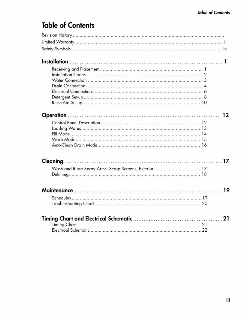
Revision History ................................................................................................................ iLimited Warranty ............................................................................................................. iiSafety Symbols ................................................................................................................ iv
Table of Contents
Table of Contents
Installation ......................................................................................... 1 Receiving and Placement ............................................................................ 1 Installation Codes ...................................................................................... 2 Water Connection ..................................................................................... 3 Drain Connection ...................................................................................... 4 Electrical Connection .................................................................................. 6 Detergent Set-up ........................................................................................ 8 Rinse-Aid Set-up ....................................................................................... 10
Operation ......................................................................................... 12 Control Panel Description.......................................................................... 12 Loading Wares ........................................................................................ 13 Fill Mode ................................................................................................ 14 Wash Mode ............................................................................................ 15 Auto-Clean Drain Mode ............................................................................ 16
Cleaning ............................................................................................17 Wash and Rinse Spray Arms, Scrap Screens, Exterior .................................. 17 Deliming ................................................................................................. 18
Maintenance .......................................................................................19 Schedules ................................................................................................19 Troubleshooting Chart ...............................................................................20
Timing Chart and Electrical Schematic ....................................................21 Timing Chart ............................................................................................21 Electrical Schematic ..................................................................................22
iii
Safety Symbols
Safety Symbols
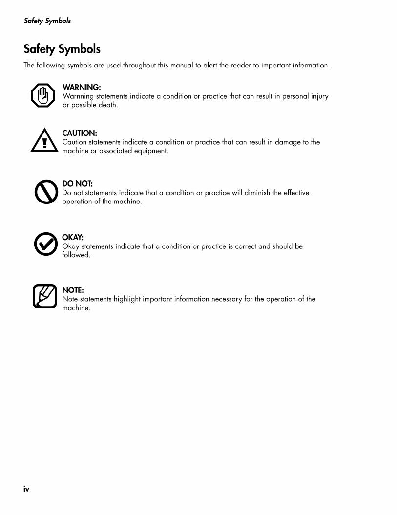
WARNING: Warnning statements indicate a condition or practice that can result in personal injury or possible death.
CAUTION: Caution statements indicate a condition or practice that can result in damage to the machine or associated equipment.
DO NOT: Do not statements indicate that a condition or practice will diminish the effective operation of the machine.
OKAY: Okay statements indicate that a condition or practice is correct and should be followed.
NOTE: Note statements highlight important information necessary for the operation of the machine.
The following symbols are used throughout this manual to alert the reader to important information.
iv
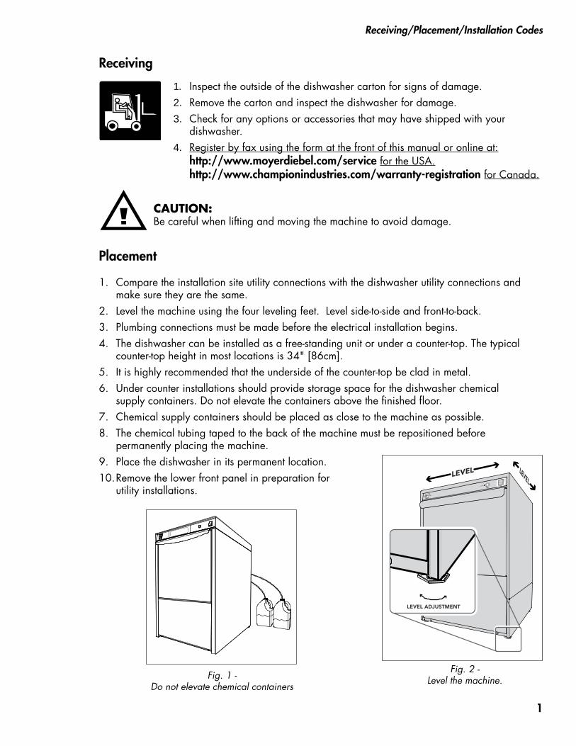
Receiving
1. Compare the installation site utility connections with the dishwasher utility connections and make sure they are the same.
2. Level the machine using the four leveling feet. Level side-to-side and front-to-back.3. Plumbing connections must be made before the electrical installation begins.4. The dishwasher can be installed as a free-standing unit or under a counter-top. The typical
counter-top height in most locations is 34" [86cm].5. It is highly recommended that the underside of the counter-top be clad in metal.6. Under counter installations should provide storage space for the dishwasher chemical
supply containers. Do not elevate the containers above the finished floor.7. Chemical supply containers should be placed as close to the machine as possible.8. The chemical tubing taped to the back of the machine must be repositioned before
permanently placing the machine.9. Place the dishwasher in its permanent location.10. Remove the lower front panel in preparation for
utility installations.
Receiving/Placement/Installation Codes
1. Inspect the outside of the dishwasher carton for signs of damage.2. Remove the carton and inspect the dishwasher for damage.3. Check for any options or accessories that may have shipped with your
dishwasher.4. Register by fax using the form at the front of this manual or online at:
http://www.moyerdiebel.com/service for the USA. http://www.championindustries.com/warranty-registration for Canada.
CAUTION:Be careful when lifting and moving the machine to avoid damage.
Placement
Fig. 2 - Level the machine.
0 60
10
20 4030
50
psi
LEVELLEVEL
LEVEL ADJUSTMENT
Fig. 1 - Do not elevate chemical containers
1
Installation
The installation of the dishwasher must comply with all local electrical, plumbing, health, and safety codes or in the absence of local codes, installed in accordance with the applicable require-ments in the National Electrical Code, NFPA 70, Canadian Electrical Code (CEC), Part 1, CSA C22.1; and the Standard for Ventilation Control and Fire Protection of Commercial Cooking Operations, NFPA 96.
Installation Codes
NOTE:The installation of your dishwasher must be performed by qualified service personnel familiar with food service equipment and must comply with all local health codes. Problems due to improper installation are not covered by the Limited Warranty.
STOP STOP
ALL PLUMBING CONNECTIONS MUST BE MADE BEFORE THE ELECTRICAL INSTALLATION. DAMAGE TO THE WATER HEATERS WILL OCCUR IF POWER IS TURNED ON WITHOUT AN
ADEQUATE WATER SUPPLY.
DAMAGE DUE TO IMPROPER INSTALLATION IS NOT COVERED BY THE LIMITED WARRANTY.
2
Installation
Water Connection
Continued on the next page.
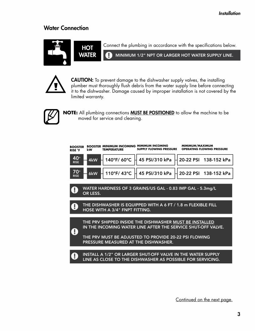
CAUTION: To prevent damage to the dishwasher supply valves, the installing plumber must thoroughly flush debris from the water supply line before connecting it to the dishwasher. Damage caused by improper installation is not covered by the limited warranty.
HOT WATER
Connect the plumbing in accordance with the specifications below.
NOTE: All plumbing connections MUST BE POSITIONED to allow the machine to be moved for service and cleaning.
INSTALL A 1/2" OR LARGER SHUT-OFF VALVE IN THE WATER SUPPLY LINE AS CLOSE TO THE DISHWASHER AS POSSIBLE FOR SERVICING.
THE PRV SHIPPED INSIDE THE DISHWASHER MUST BE INSTALLED IN THE INCOMING WATER LINE AFTER THE SERVICE SHUT-OFF VALVE. THE PRV MUST BE ADJUSTED TO PROVIDE 20-22 PSI FLOWING PRESSURE MEASURED AT THE DISHWASHER.
THE DISHWASHER IS EQUIPPED WITH A 6 FT / 1.8 m FLEXIBLE FILL HOSE WITH A 3/4" FNPT FITTING.
WATER HARDNESS OF 3 GRAINS/US GAL - 0.83 IMP GAL - 5.3mg/L OR LESS.
BOOSTER RISE °F
BOOSTER kW
MINIMUM INCOMING TEMPERATURE
MIMIMUM INCOMING SUPPLY FLOWING PRESSURE
MIMIMUM/MAXIMUM OPERATING FLOWING PRESSURE
MINIMUM 1/2" NPT OR LARGER HOT WATER SUPPLY LINE.
20-22 PSI 138-152 kPa
45 PSI/310 kPa
45 PSI/310 kPa
110°F/ 43°C 70° RISE
6kW
40° RISE 4kW 140°F/ 60°C
20-22 PSI 138-152 kPa
3
Installation
Drain Connection
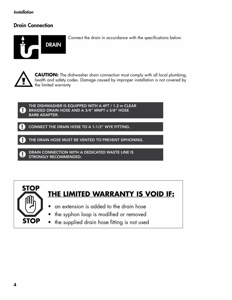
DRAINConnect the drain in accordance with the specifications below.
CAUTION: The dishwasher drain connection must comply with all local plumbing, health and safety codes. Damage caused by improper installation is not covered by the limited warranty
THE LIMITED WARRANTY IS VOID IF:
• an extension is added to the drain hose• the syphon loop is modified or removed• the supplied drain hose fitting is not usedSTOP
STOP
DRAIN CONNECTION WITH A DEDICATED WASTE LINE IS STRONGLY RECOMMENDED.
CONNECT THE DRAIN HOSE TO A 1-1/2" WYE FITTING.
THE DISHWASHER IS EQUIPPED WITH A 4FT / 1.2 m CLEAR BRAIDED DRAIN HOSE AND A 3/4" MNPT x 5/8" HOSE BARB ADAPTER.
THE DRAIN HOSE MUST BE VENTED TO PREVENT SIPHONING.
4
Installation
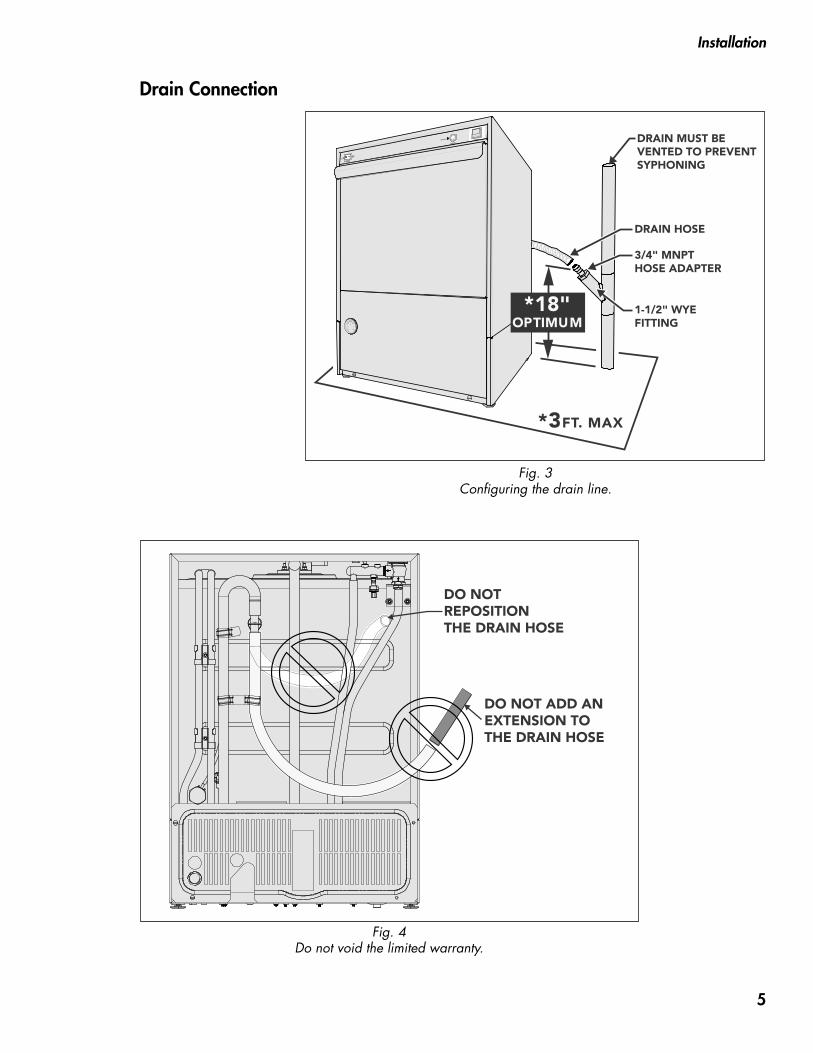
DO NOTREPOSITIONTHE DRAIN HOSE
DO NOT ADD AN EXTENSION TO THE DRAIN HOSE
0 60
10
20 4030
50
psi
3/4" MNPT HOSE ADAPTER
DRAIN HOSE
DRAIN MUST BEVENTED TO PREVENTSYPHONING
1-1/2" WYEFITTING
*18"OPTIMUM
*3FT. MAX
Fig. 3 Configuring the drain line.
Drain Connection
Fig. 4 Do not void the limited warranty.
5

0 60
10
20 4030
50
psi
DATA PLATE
FRONT PANELSCREW LOCATION
Installation
Electrical Connection
WARNING: Electrocution may occur when working on ener-gized circuits. Disconnect power at the main breaker or service disconnect switch, then lock out and tag it to indicate that work is being performed on the circuit.
CAUTION: Electrical connections must be made AFTER the plumbing installation. Damage to the water heaters will occur if the power is turned on without an adequate water supply.
Follow the instructions below and on the next page to connect power to the machine.
1
Elec. SpecsRated Amps
Minimum Supply Circuit
Ampacity
Maximum Overcurrent Overcurrent
Protective Device
208/60/1 29 40 40
240/60/1 31 40 40
Elec. SpecsRated Amps
Minimum Supply Circuit
Ampacity
Maximum
(Breaker Size) (Breaker Size)
Protective Device
208/60/1 22 30 30
240/60/1 24 30 30
383HT 40˚F/22˚C Rise Electric Booster (4kW) 383HT 70˚F/39˚C Rise Electric Booster (6kW)
Table - 1 Breaker (Service Disconnect Switch) Size
Fig. 5
CHECK THE ELECTRICAL SPECIFICA- TIONS ON MACHINE DATA PLATE. REFER TO THE BREAKER SIZE TABLE BELOW AND ENSURE THE BUILDING BREAKER SIZE MATCHES. REMOVE DISHWASHER LOWER FRONT PANEL TO ACCESS INTERNAL COMPONENTS FOR INSTALLATION.
6

Installation
Electrical Connection (continued)
A
BTERMINALENCLOSURE
2
Fig. 6
GROUND LUGSTRAIN-RELIEFKNOCKOUT
B
A3
Fig. 7
L1 L2 N
L1 L2NEUTRAL
208/240V
115V
115V
G
Fig. 8
4
REMOVE THE LEFT SCREW ON THE FRONT LIP OF THE TERMINAL BOX. LIFT AND REMOVE THE COVER TO ACCESS THE TERMINAL BLOCK.
A
B
A 30" / 76 cm SERVICE LOOP MUST BE PROVIDED BEHIND THE UNIT FOR SERVICING.
STOP
STOP
THREAD THE POWER CABLE THROUGH THE MIDDLE SLOT IN THE REAR PANEL. SECURE THE CABLE TO THE TERMINAL BOX USING THE PROPER STRAIN RELIEF.
A
B
208-240V / 60Hz / 1 Ø 115V SPLIT CONNECTION SINGLE PHASE - THREE WIRE PLUS GROUND WHICH INCLUDES A CURRENT CARRYING NEUTRAL WIRE RATED MIN 190°F (88°C).
CONNECT THE INCOMING POWER AS SHOWN IN FIG. 8.
7
Installation
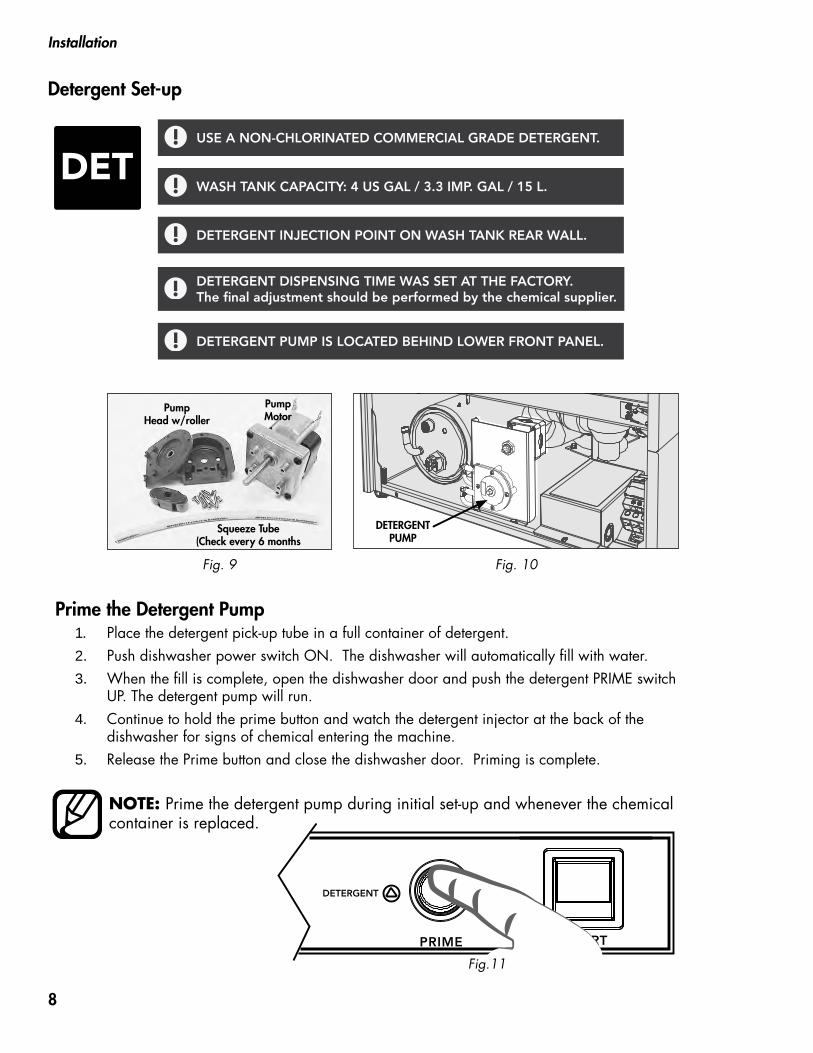
Detergent Set-up
DET
DETERGENT PUMP
Fig. 10
Fig.11
Pump Motor
Pump Head w/roller
Squeeze Tube (Check every 6 months
Fig. 9
1. Place the detergent pick-up tube in a full container of detergent.2. Push dishwasher power switch ON. The dishwasher will automatically fill with water.3. When the fill is complete, open the dishwasher door and push the detergent PRIME switch
UP. The detergent pump will run.4. Continue to hold the prime button and watch the detergent injector at the back of the
dishwasher for signs of chemical entering the machine.5. Release the Prime button and close the dishwasher door. Priming is complete.
Prime the Detergent Pump
NOTE: Prime the detergent pump during initial set-up and whenever the chemical container is replaced.
USE A NON-CHLORINATED COMMERCIAL GRADE DETERGENT.
WASH TANK CAPACITY: 4 US GAL / 3.3 IMP. GAL / 15 L.
DETERGENT INJECTION POINT ON WASH TANK REAR WALL.
DETERGENT DISPENSING TIME WAS SET AT THE FACTORY. The final adjustment should be performed by the chemical supplier.
DETERGENT PUMP IS LOCATED BEHIND LOWER FRONT PANEL.
8
VIEW FROM REAR OF UNIT
POWER SWITCH START SWITCH
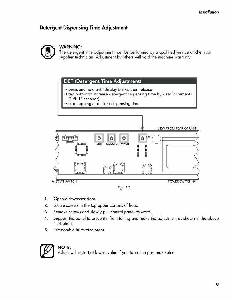
DET (Detergent Time Adjustment)
press and hold until display blinks, then releasetap button to increase detergent dispensing time by 2 sec increments (1 12 seconds)stop tapping at desired dispensing time
••
•
Skip BOOSTER WASH
DET
Detergent Dispensing Time Adjustment
1. Open dishwasher door.2. Locate screws in the top upper corners of hood.3. Remove screws and slowly pull control panel forward.4. Support the panel to prevent it from falling and make the adjustment as shown in the above
illustration.5. Reassemble in reverse order.
WARNING: The detergent time adjustment must be performed by a qualified service or chemical supplier technician. Adjustment by others will void the machine warranty.
Installation
NOTE:Values will restart at lowest value if you tap once past max value.
Fig. 12
9
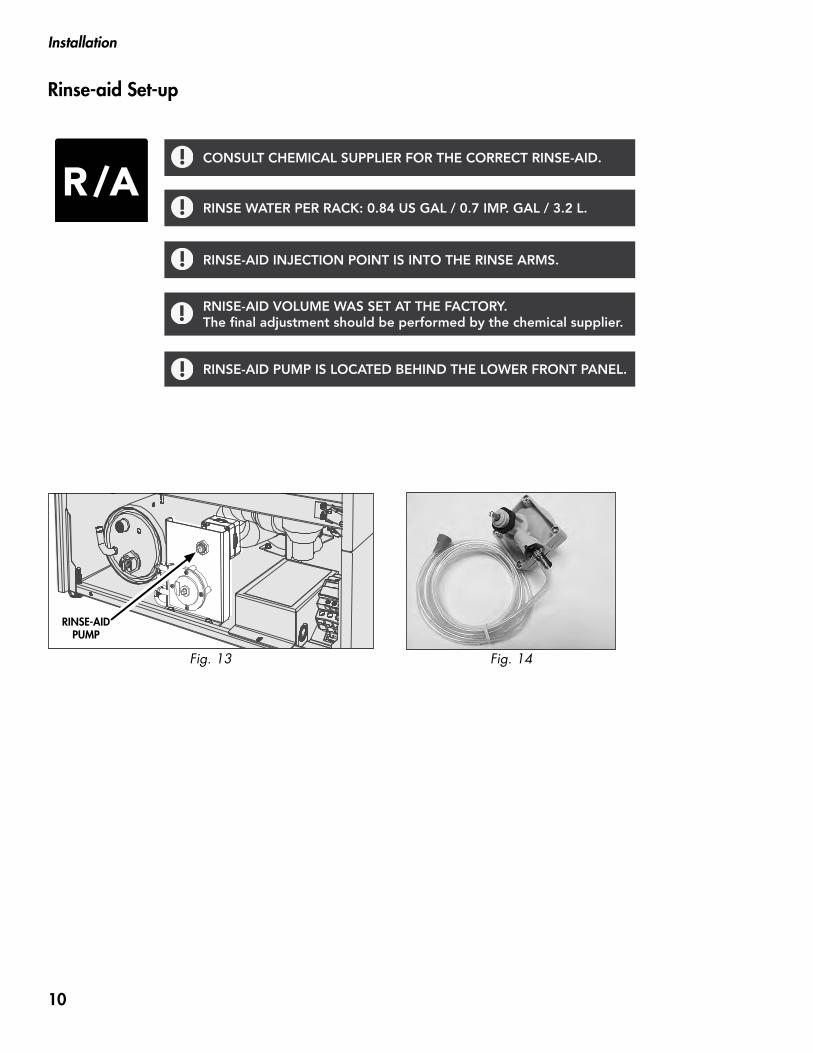
Rinse-aid Set-up
R/A
Fig. 13
RINSE-AID PUMP
Fig. 14
CONSULT CHEMICAL SUPPLIER FOR THE CORRECT RINSE-AID.
RNISE-AID VOLUME WAS SET AT THE FACTORY. The final adjustment should be performed by the chemical supplier.
RINSE-AID INJECTION POINT IS INTO THE RINSE ARMS.
RINSE WATER PER RACK: 0.84 US GAL / 0.7 IMP. GAL / 3.2 L.
RINSE-AID PUMP IS LOCATED BEHIND THE LOWER FRONT PANEL.
Installation
10
Installation
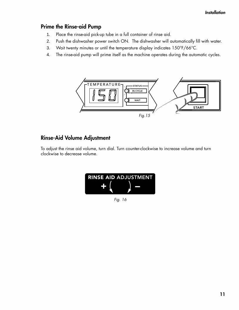
Fig.15
1. Place the rinse-aid pick-up tube in a full container of rinse aid.2. Push the dishwasher power switch ON. The dishwasher will automatically fill with water.3. Wait twenty minutes or until the temperature display indicates 150°F/66°C.4. The rinse-aid pump will prime itself as the machine operates during the automatic cycles.
Prime the Rinse-aid Pump
Rinse-Aid Volume Adjustment
To adjust the rinse aid volume, turn dial. Turn counter-clockwise to increase volume and turn clockwise to decrease volume.
Fig. 16
11

Operation
Control Panel Description
A B C D E F GFig. 17
H
A - ON-OFF/Drain power switch turns power on and off. It initiates the automatic fill cycle when turned on and the automatic drain cycle when turned off.
B- WASH INDICATOR light illuminates whenever the temperature display indicates the water temperature in the wash tank.
C- RINSE INDICATOR light illuminates whenever the temperature display indicates the final rinse water temperature.
D- TEMPERATURE DISPLAY indicates water temperature and displays operation codes for the operator. The minimum wash water temperature is 150°F/66°C. The minimum/maximum final rinse temperature is 180-195°F/ 82-91°C.
E - IN CYCLE INDICATOR light illuminates during the initial fill, the automatic timed cycle, and during the automatic drain cycle.
F- WAIT INDICATOR light illuminates during the initial fill and as the booster heats to the minimum 180°F/82°C. The indicator light goes out when 180°F/82°C is achieved.
G- DETERGENT PRIME SWITCH when pressed, runs the detergent dispensing pump to prime the pick-up hose during initial set-up and whenever the detergent supply container is changed.
H- START PUSH BUTTON Pressing the START button initiates an automatic timed cycle and illuminates the IN CYCLE light. I- PRESSURE GAUGE indicates the final rinse water flowing pressure during the initial fill and the automatic final rinse cycle. The proper pressure reading is 20-22 PSI. The pressure gauge is located on the left side of the lower front panel.
10
0
3020
PSI
60
50
40
PRESSURE20-22 PSI
I
Fig. 18
12
Operation
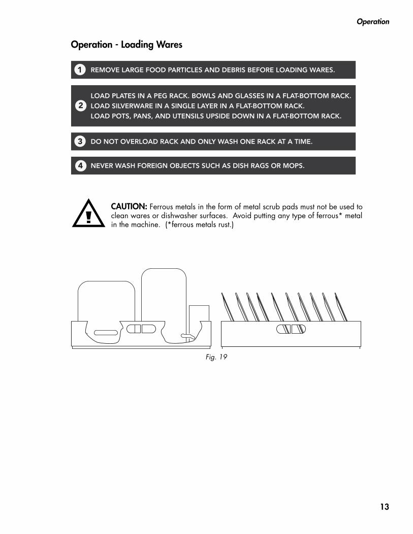
Operation - Loading Wares
CAUTION: Ferrous metals in the form of metal scrub pads must not be used to clean wares or dishwasher surfaces. Avoid putting any type of ferrous* metal in the machine. (*ferrous metals rust.)
Fig. 19
REMOVE LARGE FOOD PARTICLES AND DEBRIS BEFORE LOADING WARES.1
LOAD PLATES IN A PEG RACK. BOWLS AND GLASSES IN A FLAT-BOTTOM RACK.
LOAD SILVERWARE IN A SINGLE LAYER IN A FLAT-BOTTOM RACK.
LOAD POTS, PANS, AND UTENSILS UPSIDE DOWN IN A FLAT-BOTTOM RACK.
2
DO NOT OVERLOAD RACK AND ONLY WASH ONE RACK AT A TIME.3
NEVER WASH FOREIGN OBJECTS SUCH AS DISH RAGS OR MOPS.4
13

Operation
Operation - Fill Mode
1 Check chemical levels in containers
Containers must be at floor level.
0 60
10
20 4030
50
psi
2 Push the lighted ON-OFF/DRAIN switch to the ON position. The switch illuminates.
!
Wait 20 minutes for temperaturedisplay to read 150°F/66°C.
WAIT light goes out and the WASH light comes onwhen temperature is achieved.
20MINUTES
4
!
Display indicates "FIL".Machine fills with water.
The IN CYCLE and WAIT lights illuminate.
3
Flashing "LP" display indicates aproblem with the water supply.
FILL SENTRY FEATURE FILL SENTRY - LP ( Low Pressure )
The Fill Sentry monitors the water supply and extends the initial fill time if needed. The dishwasher will stop and drain if the proper initial fill is not achieved. Inspect the water supply for kinked lines, partially closed valves, or low incoming water pressure. Push the dishwasher power switch off and on to reset the flashing "LP" display. The dish- washer will refill.
14
Operation
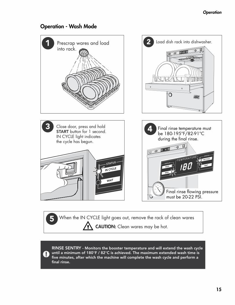
1 Prescrap wares and loadinto rack.
Operation - Wash Mode
3 Close door, press and hold START button for 1 second.IN CYCLE light indicatesthe cycle has begun.
2 Load dish rack into dishwasher.
0 60
10
20 4030
50
psi
Final rinse temperature mustbe 180-195°F/82-91°Cduring the final rinse.
0 60
10
20 4030
50
psi
Final rinse flowing pressuremust be 20-22 PSI.
4
0 60
10
20 4030
50
psi
5 When the IN CYCLE light goes out, remove the rack of clean wares
CAUTION: Clean wares may be hot.
RINSE SENTRY - Monitors the booster temperature and will extend the wash cycle until a minimum of 180°F / 82°C is achieved. The maximum extended wash time is five minutes, after which the machine will complete the wash cycle and perform a final rinse.
15
Operation
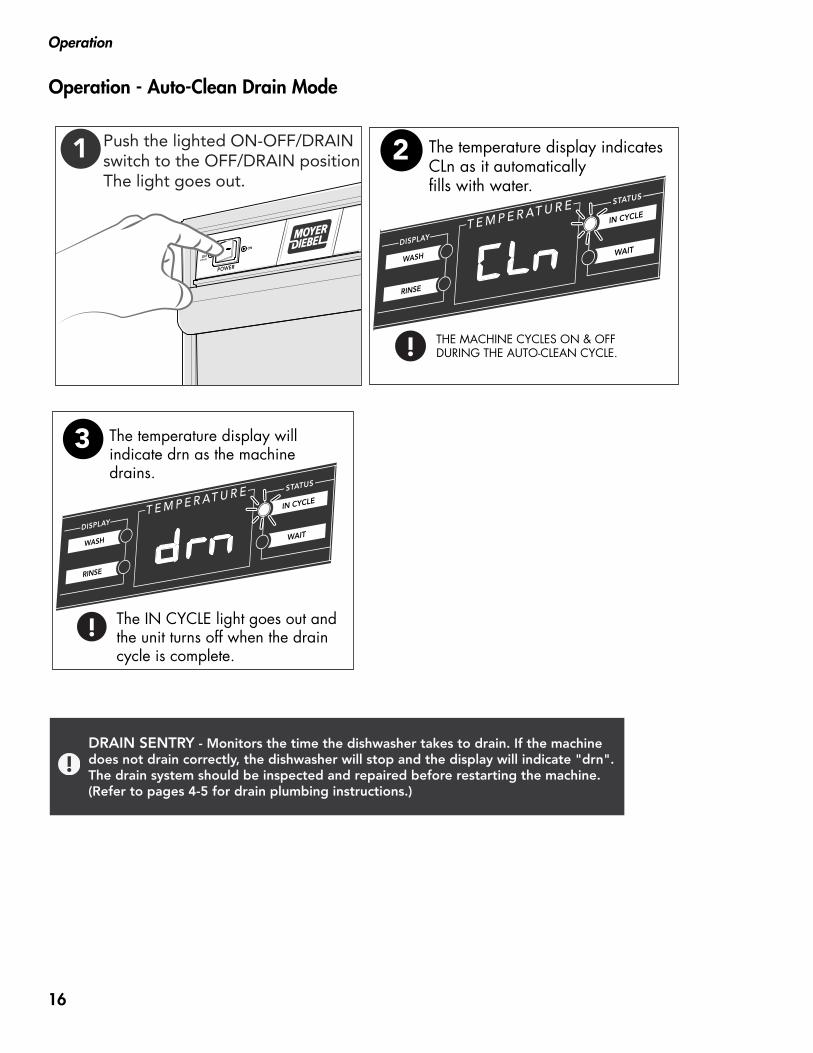
Operation - Auto-Clean Drain Mode
!
The temperature display indicatesCLn as it automaticallyfills with water.
THE MACHINE CYCLES ON & OFFDURING THE AUTO-CLEAN CYCLE.
2
!
The temperature display willindicate drn as the machinedrains.
The IN CYCLE light goes out and the unit turns off when the draincycle is complete.
3
1 Push the lighted ON-OFF/DRAIN switch to the OFF/DRAIN position. The light goes out.
DRAIN SENTRY - Monitors the time the dishwasher takes to drain. If the machine does not drain correctly, the dishwasher will stop and the display will indicate "drn". The drain system should be inspected and repaired before restarting the machine. (Refer to pages 4-5 for drain plumbing instructions.)
16
Cleaning
Cleaning
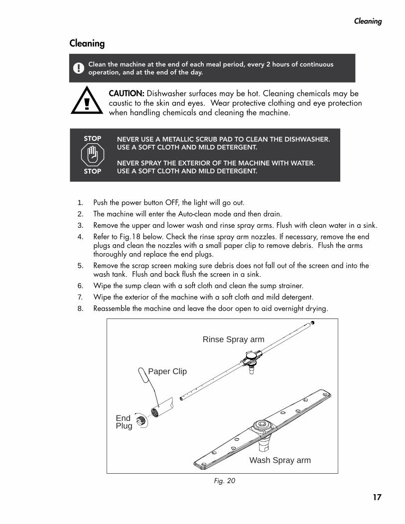
1. Push the power button OFF, the light will go out.2. The machine will enter the Auto-clean mode and then drain. 3. Remove the upper and lower wash and rinse spray arms. Flush with clean water in a sink. 4. Refer to Fig.18 below. Check the rinse spray arm nozzles. If necessary, remove the end
plugs and clean the nozzles with a small paper clip to remove debris. Flush the arms thoroughly and replace the end plugs.
5. Remove the scrap screen making sure debris does not fall out of the screen and into the wash tank. Flush and back flush the screen in a sink.
6. Wipe the sump clean with a soft cloth and clean the sump strainer.7. Wipe the exterior of the machine with a soft cloth and mild detergent.8. Reassemble the machine and leave the door open to aid overnight drying.
Fig. 20
CAUTION: Dishwasher surfaces may be hot. Cleaning chemicals may be caustic to the skin and eyes. Wear protective clothing and eye protection when handling chemicals and cleaning the machine.
Wash Spray arm
Paper Clip
EndPlug
Rinse Spray arm
Clean the machine at the end of each meal period, every 2 hours of continuous operation, and at the end of the day.
NEVER USE A METALLIC SCRUB PAD TO CLEAN THE DISHWASHER. USE A SOFT CLOTH AND MILD DETERGENT. NEVER SPRAY THE EXTERIOR OF THE MACHINE WITH WATER. USE A SOFT CLOTH AND MILD DETERGENT.
STOP
STOP
17

Cleaning
Cleaning - Deliming
WARNING: Death or serious injury may result when deliming solution is mixed with sodium hypochlorite (chlorine bleach) sanitizing agent. Mixing may cause hazardous gases to form. Deliming solution and other acids must never be mixed with chlorine, iodine, bromine, or fluorine. Deliming solutions can cause severe irritation and possible chemical burns. Always wear protective clothing and goggles when handling chemicals.
Follow the steps below to delime the dishwasher.
1. Open the dishwasher door and remove the dish rack.
2. Remove the detergent and rinse-aid chemical supply tubing from their chemical supply containers.
3. Place the pick-up tubes in a container of hot water.
4. Push the dishwasher power switch to the ON position. The dishwasher will fill with water.
5. Press and hold the detergent prime switch UP to flush the detergent from the supply tubing. Release the switch.
6. Turn the dishwasher power switch to OFF/DRAIN to drain the wash tank. The WASH indicator light will go out in about 2 minutes.
7. Always wear eye protection, rubber gloves and protective clothing when handling chemicals.
8. Open the door and carefully add the deliming chemical to the wash tank in accordance with your chemical supplier's instructions. Be careful to avoid splashing.
9. Close the door.
10. Press the power switch to the ON position. The machine will fill with water.
11. Press and hold the Start button for one second to initiate an automatic cycle.
12. When the cycle has ended, open the door and check the deliming results. Repeat steps 6-11 if necessary. Push the power switch to OFF/Drain to drain the machine.
13. Push the power switch ON to refill the machine. Place an empty dish rack in the machine.
14. Run 4 empty cycles to ensure all deliming chemicals are flushed from the machine.
15. Return chemical supply tubing to their containers and prime the chemical lines.
16. Deliming is complete.
18
Maintenance
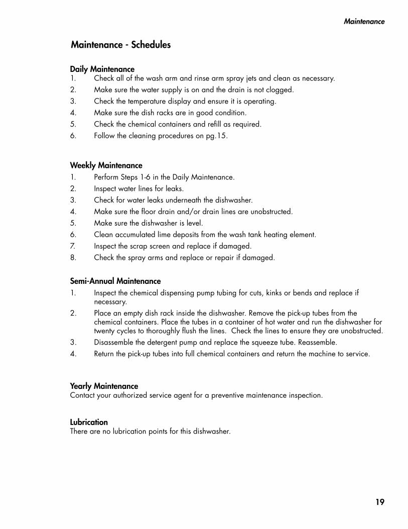
Daily Maintenance1. Check all of the wash arm and rinse arm spray jets and clean as necessary.2. Make sure the water supply is on and the drain is not clogged.3. Check the temperature display and ensure it is operating.4. Make sure the dish racks are in good condition.5. Check the chemical containers and refill as required.6. Follow the cleaning procedures on pg.15.
Weekly Maintenance1. Perform Steps 1-6 in the Daily Maintenance.2. Inspect water lines for leaks.3. Check for water leaks underneath the dishwasher.4. Make sure the floor drain and/or drain lines are unobstructed.5. Make sure the dishwasher is level.6. Clean accumulated lime deposits from the wash tank heating element.7. Inspect the scrap screen and replace if damaged.8. Check the spray arms and replace or repair if damaged.
Semi-Annual Maintenance1. Inspect the chemical dispensing pump tubing for cuts, kinks or bends and replace if necessary. 2. Place an empty dish rack inside the dishwasher. Remove the pick-up tubes from the chemical containers. Place the tubes in a container of hot water and run the dishwasher for twenty cycles to thoroughly flush the lines. Check the lines to ensure they are unobstructed.3. Disassemble the detergent pump and replace the squeeze tube. Reassemble.4. Return the pick-up tubes into full chemical containers and return the machine to service.
Yearly MaintenanceContact your authorized service agent for a preventive maintenance inspection.
LubricationThere are no lubrication points for this dishwasher.
Maintenance - Schedules
19
Maintenance
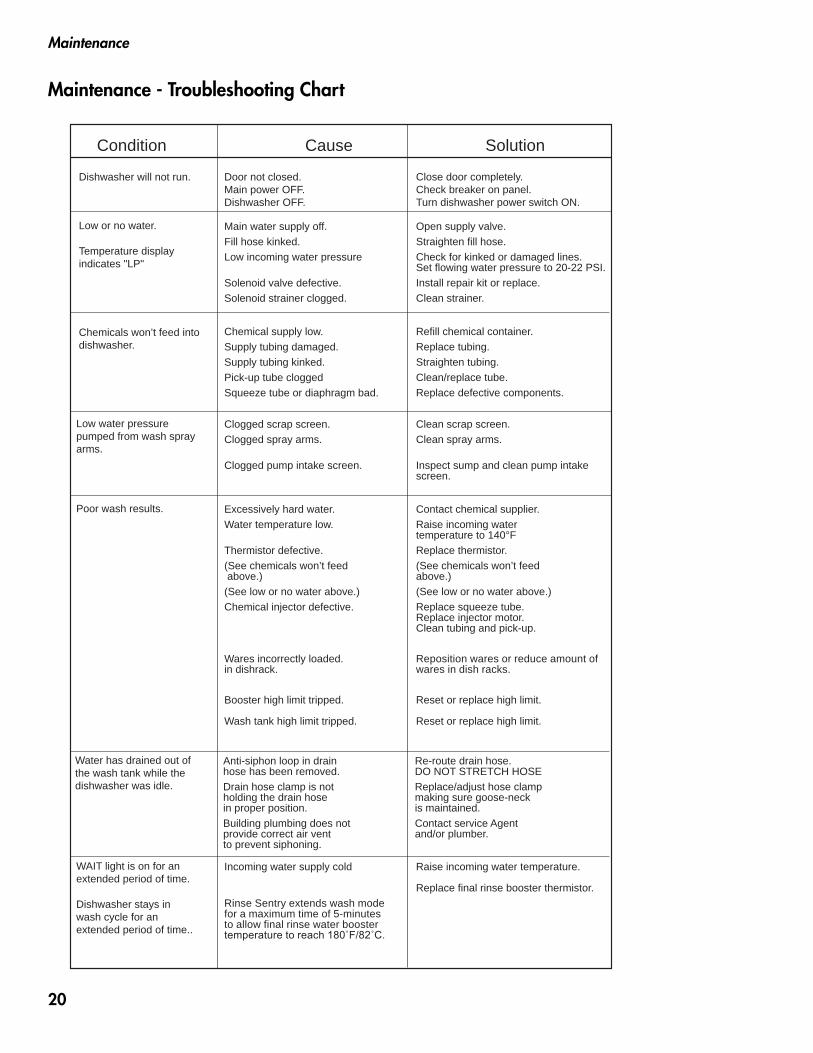
Condition Cause Solution
Dishwasher will not run.
Low or no water.
Temperature display indicates "LP"
Chemicals won’t feed intodishwasher.
Door not closed.Main power OFF.Dishwasher OFF.
Main water supply off.Fill hose kinked.Low incoming water pressure
Solenoid valve defective.Solenoid strainer clogged.
Chemical supply low.Supply tubing damaged.Supply tubing kinked.Pick-up tube cloggedSqueeze tube or diaphragm bad.
Close door completely.Check breaker on panel.Turn dishwasher power switch ON.
Open supply valve.Straighten fill hose.Check for kinked or damaged lines.Set flowing water pressure to 20-22 PSI.Install repair kit or replace.Clean strainer.
Refill chemical container.Replace tubing.Straighten tubing.Clean/replace tube.Replace defective components.
Low water pressurepumped from wash spray arms.
Clogged scrap screen.Clogged spray arms.
Clogged pump intake screen.
Clean scrap screen.Clean spray arms.
Inspect sump and clean pump intake screen.
WAIT light is on for anextended period of time.
Dishwasher stays inwash cycle for an extended period of time..
Incoming water supply cold
Rinse Sentry extends wash mode for a maximum time of 5-minutes to allow final rinse water booster temperature to reach 180˚F/82˚C.
Raise incoming water temperature.
Replace final rinse booster thermistor.
Poor wash results. Excessively hard water.Water temperature low.
Thermistor defective.(See chemicals won’t feed above.)(See low or no water above.)Chemical injector defective.
Wares incorrectly loaded. in dishrack.
Booster high limit tripped.
Wash tank high limit tripped.
Contact chemical supplier.Raise incoming watertemperature to 140°FReplace thermistor.(See chemicals won’t feedabove.)(See low or no water above.)Replace squeeze tube.Replace injector motor.Clean tubing and pick-up.
Reposition wares or reduce amount of wares in dish racks.
Reset or replace high limit.
Reset or replace high limit.
Water has drained out of the wash tank while the dishwasher was idle.
Anti-siphon loop in drainhose has been removed.Drain hose clamp is notholding the drain hose in proper position.Building plumbing does notprovide correct air ventto prevent siphoning.
Re-route drain hose.DO NOT STRETCH HOSEReplace/adjust hose clampmaking sure goose-neckis maintained.Contact service Agentand/or plumber.
Maintenance - Troubleshooting Chart
20
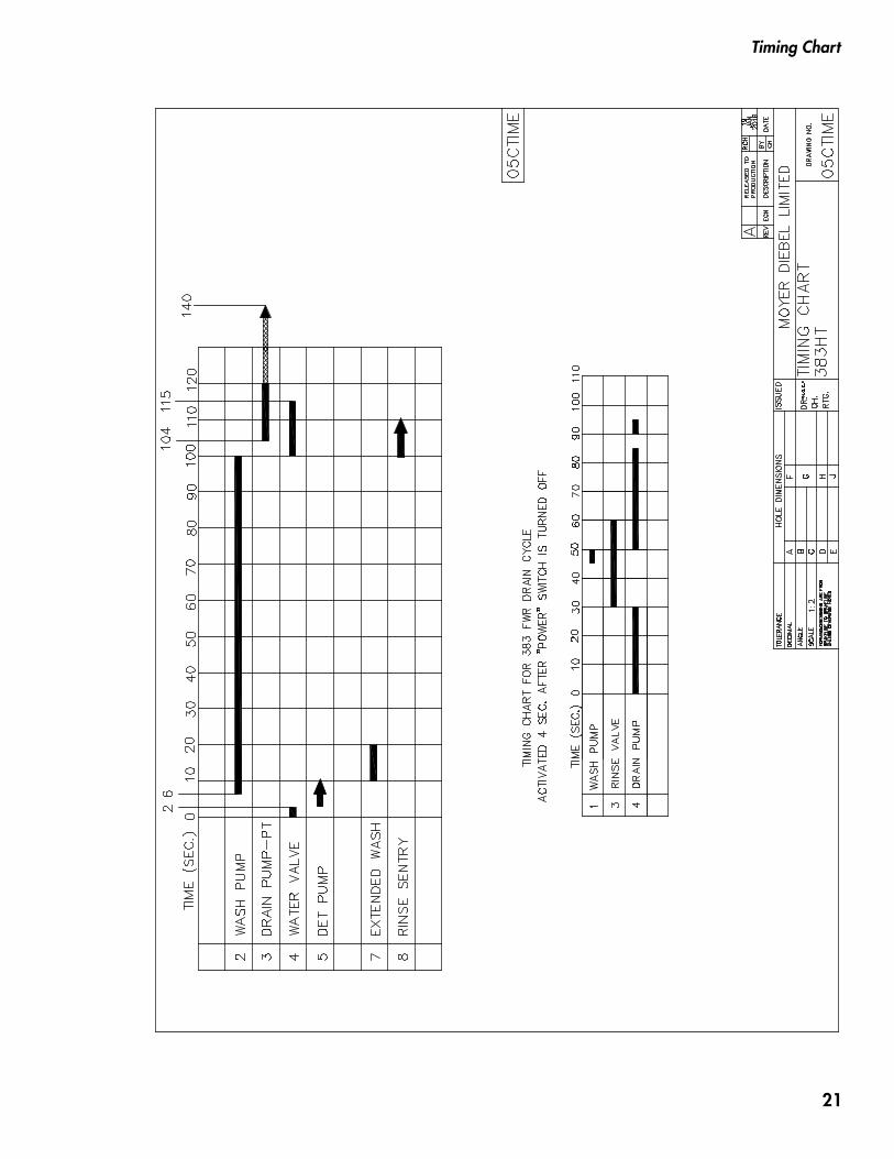
Timing Chart
21
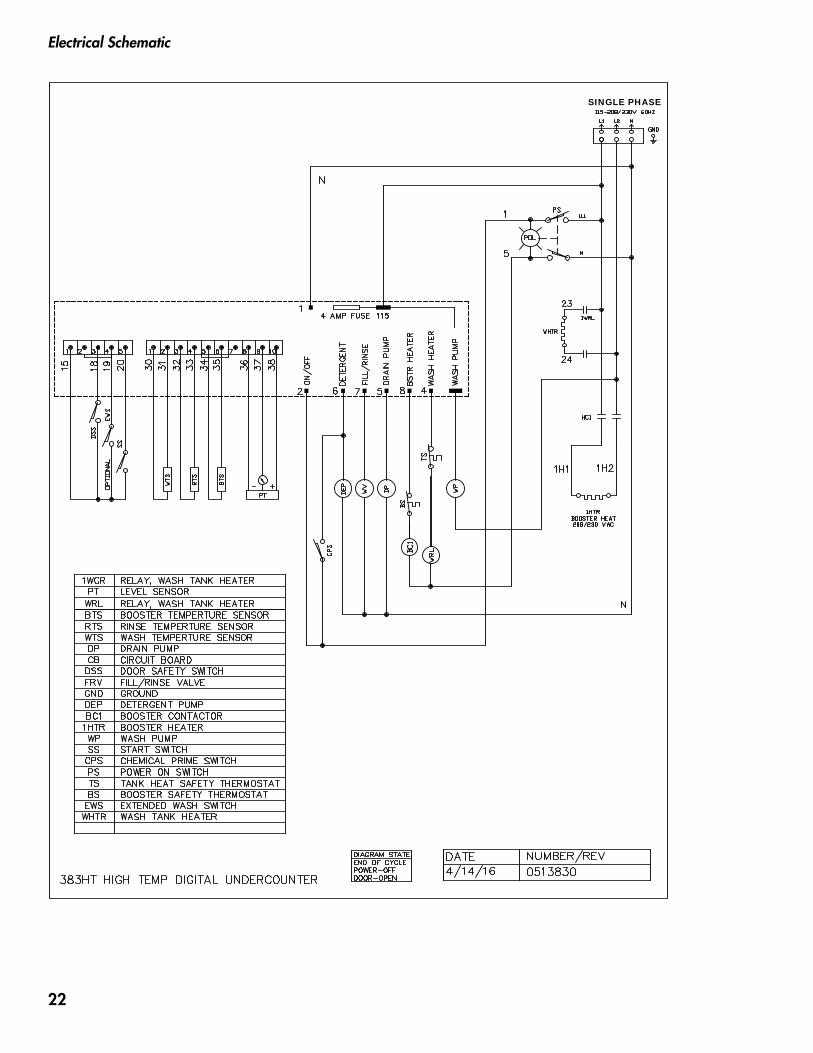
Electrical Schematic
SINGLE PHASE
22

23

24