Embed Size (px)
Citation preview
Composites: Part A 100 (2017) 161–169
Contents lists available at ScienceDirect
Composites: Part A
journal homepage: www.elsevier .com/locate /composi tesa
High strain-rate dynamic mechanical properties of Kevlar fabricsimpregnated with shear thickening fluid
http://dx.doi.org/10.1016/j.compositesa.2017.04.0151359-835X/� 2017 Published by Elsevier Ltd.
⇑ Corresponding author.E-mail addresses: [email protected] (S. Xuan), [email protected] (X. Gong).
Saisai Cao a, Qian Chen a, Yunpeng Wang a, Shouhu Xuan a,⇑, Wanquan Jiang b, Xinglong Gong a,⇑aCAS Key Laboratory of Mechanical Behavior and Design of Materials, Department of Modern Mechanics, University of Science and Technology of China (USTC), Hefei 230027, PR ChinabDepartment of Chemistry, USTC, Hefei 230026, PR China
a r t i c l e i n f o
Article history:Received 18 January 2017Received in revised form 27 March 2017Accepted 20 April 2017Available online 22 April 2017
Keywords:A. Fabrics/textilesA. NanoparticlesB. Impact behaviorD. Mechanical testingShear thickening fluid
a b s t r a c t
To investigate the anti-impact mechanism, the mechanical property and energy absorption of the STFimpregnated Kevlar (STF/Kevlar) fabric at high strain rate were conducted using a split Hopkinson pres-sure bar (SHPB) system. The volume fraction of STF, number of fabric specimens, and impact velocityhighly affected the dynamic mechanical performance of the STF/Kevlar composite. The energy transferrate decreased from 0.85 to 0.01 once the number of fabric specimens increased from 2 layers to 8 layers.The strain rate stiffening mechanism of the STF/Kevlar was analyzed. The Kevlar fabrics underwent foursections during the impact process. The STF was mainly worked in the slip and deformation section byenhancing the friction between fabric yarns and preventing the fabric yarns from slipping. Overall, thiswork demonstrated that the multilayer Kevlar fabrics impregnated with high volume fraction of STF werethe optimal choice for soft body armor.
� 2017 Published by Elsevier Ltd.
1. Introduction
Body armors are designed to protect soldiers from the damagecaused by bullets and other weapons. The traditional body armorsare made of ceramics and metal, which makes the body armorsbulky. To improve the flexibility and reduce the weight of the bodyarmors, high strength and energy absorption fabrics such as Kevlar,Twaron and Spectra have been developed for the soft body armors[1–3]. Usually, almost 20–50 layers of fabrics are required to satisfythe bulletproof requirements. As a result, the comfort of the bodyarmors sharply decreases. Therefore, besides the ballistic require-ment, the low weight and high flexibility become the critical pointsfor body armors. Recent years, shear thickening fluid (STF) has gotmore and more attention due to its unique shear thickening prop-erty. As a type of non-newton fluid, the viscosity of STF increasesdramatically when the shear rate exceeds a critical value. After eas-ing the applied shear rate, the STF can recover from solid like stateto the initial fluid state [4–8]. The shear thickening property isexpected to enhance the ballistic performance of fabrics. Therefore,the STF incorporated Kevlar has been proven to be an ideal bodyarmor because of its low density [9–15].
In the early days, a lot of researches were conducted on the stabresistance of STF impregnated (STF-treated) fabric composite [9–
20]. Decker et al. [9] investigated the stab resistance of STF-treated Kevlar and nylon fabrics. It was found that the STF-treated fabric exhibited significant improvements in punctureresistance while a slight enhancement in cut protection. Fenget al. [15] prepared different STFs based on the fumed silica andsubmicron silica particles. After incorporating these STFs into theKevlar fabrics, the quasi-static stab resistance properties werestudied. The force-displacement curve and the microstructure dia-gram demonstrated that the properties of particles influenced thestab resistance properties of fabrics. Moreover, it was reportedthe STFs also highly affected the friction between fabric yarns[17,21–24]. Gong et al. [17] found that the pull-out force of theKevlar/STF fabrics was much larger than the neat fabric. Typically,the pull-out force of the Kevlar/STF fabrics increased with the pull-out speed, which was consistent with the shear thickening prop-erty of STFs. Meanwhile, lots of investigations on the ballistic prop-erties of the composite have been reported [18,25–29]. Park et al.[28] focused on the energy absorption of STF-treated fabric com-posite under high speed (>700 m/s) impact and studied the changeof energy absorption value with the impact velocity by changingthe number of Kevlar layers and area density.
The mechanical properties of the STF/fabric composite have gotmore and more attention since their importance for application[15,30,31]. Lu et al. [30] studied the quasi-static and low-velocityimpact compressive behavior of the warp-knitted spacer fabrics(WKSF) impregnated with STF. The compressive behavior of the
162 S. Cao et al. / Composites: Part A 100 (2017) 161–169
STF/WKSF had a significant strain rate effect. In comparison to theneat WKSF, the STF/WKSF showed a higher energy absorption anda lower peak load. Haris et al. [31] studied the STF/Twaron fabricswith a shock tube device and ballistic tests. The results showedthat the STF-treated fabrics could be applied in both ballistic pro-tection and shock wave mitigation. By using uniaxial tensile,bias-extension, and picture-frame tests, Na et al. [32] investigatedthe rate-dependent behavior of an STF-im-AR fabric. Although theSTF effect was not evident in the tensile properties, the shear resis-tance of the fabric was enhanced significantly. To further investi-gate the enhancing mechanism, Lu et al. [33] and Park et al. [34]also established a numerical simulation model to explain theenergy absorption of the composite at the viewpoint of friction.Lee and Kim [35] performed a computational analysis to considerthe effect of STF impregnation on the ballistic performance of STFimpregnated fabrics. The results showed that the increased frictioninduced by STF impregnation encouraged a greater interactionbetween yarns that allowed the fabric to maintain its woven struc-ture longer than neat fabric during the impact process.
The split Hopkinson pressure bar (SHPB) system is widely usedto test the mechanical properties of materials at high strain ratesvarying from 102 s�1 to 104 s�1 [36–43]. A stress pulse is generatedwhile the striker bar hits the incident bar. Then the specimen isdeformed by the stress pulse. Finally, the stress-strain curve ofthe specimen can be obtained from the waveforms before and afterthe specimen. Up to now, the researches on the bullet-proof fabricsimpregnated with STF are mainly in the stab resistance and ballis-tic resistance aspects. However, the high strain rate dynamic prop-erty of the STF strengthened fabrics has not been reported till now.The body armor was originally used to prevent the bullet throughthe body. However, the liver, heart, spleen, and spinal cord werestill vulnerable to injury despite of the use of soft body armor[44–46]. As we know, stress waves are generated while the high-speed bullet hits body armor, where the energy of the stress pulseis quite considerable and even deadly. Stress waves in tissue mayresult in very high local forces, producing small but very rapid dis-tortions of tissue (strain), which causes non penetrating trauma(NPT) [45]. Therefore, it is essential to investigate the dissipationof strain energy and dynamic mechanical properties of thebullet-proof fabrics impregnated with STF under impact.
In this work, the high strain-rate mechanical property of theSTF/Kevlar was studied by using SHPB system. Firstly, as a compar-ison, the stab resistance performance of the STF/Kevlar compositeswas tested by a drop tower. A knife impactor and a spike impactorwere chosen according to the National Institute of Justice (NIJ)standard for stab testing of protective armors (NIJ 0115.00,2000). Then, an SHPB systemwas used to test the mechanical prop-erties and energy absorption of the STF/Kevlar composites at highstrain rate. Finally, the mechanism for the deformation of the STF/Kevlar composites under impact was carefully discussed.
2. Materials and methods
2.1. Preparation of STFs and STF/Kevlar composites
The PSt-EA nanospheres were prepared by soap free emulsionpolymerization. The STFs were obtained by dispersing the PSt-EAnanospheres into ethylene glycol (EG). The suspension was mixedin a ball mill grinding up to about 24 h in order to obtain a uniformdistribution. In this research, different concentrations of STFs(54 vol.%, 56 vol.% and 59 vol.% for PSt-EA) were prepared.
The fabric used in the experiment was the plain-woven aramidhigh performance Kevlar fabrics with an areal density of around200 g/m2. To fabricate the STF/Kevlar composites, the STF sampleswere firstly diluted 1:2 with water and then mixed for 30 min in
ultrasonic dispersion method to ensure the solution was well-distributed. The Kevlar fabrics were cut and soaked in the solutionindividually for 5 min. After the impregnation, the fabrics weredried at 40 �C to evaporate the water. The weight of Kevlar fabricswas recorded before and after the impregnation. The detail datawas summarized in Table 1.
2.2. Methods
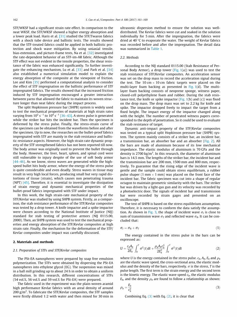
According to the NIJ standard 0115.00 (Stab Resistance of Per-sonal Body Armor), a drop tower (Fig. 1(a)) was used to test thestab resistance of STF/Kevlar composites. An acceleration sensorwas set on the drop mass to record the acceleration signal duringthe test. The 10 cm � 10 cm fabric targets were placed on themulti-layer foam backing as presented in Fig. 1(d). The multi-layer foam backing consists of neoprene sponge, witness paper,closed-cell polyethylene foam and rubber. During the stab resis-tance test, the knife or spike impactor (Fig. 1(b) and (c)) was fixedon the drop mass. The drop mass was set to 2.2 kg for knife andspike. The impactor dropped freely to impact the target from afixed height. The impact energy of the impactor changed alongwith the height. The number of penetrated witness papers corre-sponded to the depth of penetration. So it could be used to evaluatethe stab resistance of target.
Dynamic anti-impact property of the STF/Kevlar compositeswas tested on a typical split Hopkinson pressure bar (SHPB) sys-tem. The system mainly consists of a striker bar, an incident bar,a transmission bar, an absorber bar and an absorber (Fig. 2). Allthe bars are made of aluminum because of its low mechanicalimpedance. The elastic modulus of aluminum is 70 GPa and thedensity is 2700 kg/m3. In this research, the diameter of aluminumbars is 14.5 mm. The lengths of the striker bar, the incident bar andthe transmission bar are 200 mm, 1500 mm and 800 mm, respec-tively. To guarantee that the rising edge of the incident wave isgentle and the sample could obtain stress equilibrium, a rubberpulse shaper (1 mm � 1 mm) was placed on the front face of theincident bar. The fabric specimen was cut into a shape of regularoctagon to maintain geometric similarity with the bars. The strikerbar was driven by a light-gas gun and its velocity was recorded bya photoelectric door. The signals of incident bar and transmissionbar were recorded by strain gages and presented on anoscilloscope.
The test of SHPB is based on the stress equilibrium assumption.Therefore, it is necessary to conform the data satisfy the assump-tion. As shown in Fig. 3, the shape of incident wave rI is close tosum of transmission wave rT and reflected wave rR. It can be con-cluded that:
rI ¼ rR þ rT ð1Þ
The energy contained in the stress pulse in the bars can beexpressed as:
U ¼ cbAb
2Eb
Z T
0r2ðtÞdt þ qbAbc3b
2E2b
Z T
0r2ðtÞdt ð2Þ
where U is the energy contained in the stress pulse. cb, Ab, Eb and qb
are the elastic wave speed, the cross-sectional area, the elastic mod-ulus and the density of the bars, respectively. r is the stress, T is thepulse length. The first term is the strain energy and the second termis the kinetic energy. The elastic wave speed cb, the elastic modulusEb, and the density qb are found to follow a relationship as shown:
qb ¼Eb
c2bð3Þ
Combining Eq. (3) with Eq. (2), it is clear that
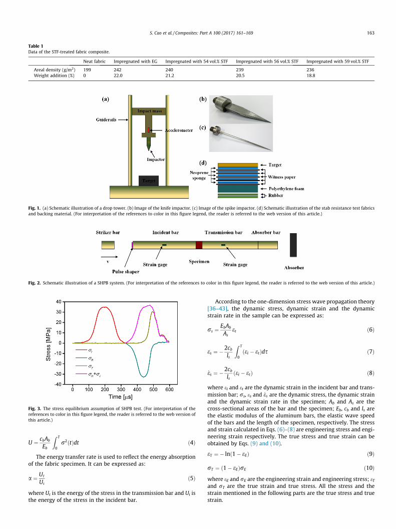
Table 1Data of the STF-treated fabric composite.
Neat fabric Impregnated with EG Impregnated with 54 vol.% STF Impregnated with 56 vol.% STF Impregnated with 59 vol.% STF
Areal density (g/m2) 199 242 240 239 236Weight addition (%) 0 22.0 21.2 20.5 18.8
Fig. 1. (a) Schematic illustration of a drop tower. (b) Image of the knife impactor. (c) Image of the spike impactor. (d) Schematic illustration of the stab resistance test fabricsand backing material. (For interpretation of the references to color in this figure legend, the reader is referred to the web version of this article.)
Fig. 2. Schematic illustration of a SHPB system. (For interpretation of the references to color in this figure legend, the reader is referred to the web version of this article.)
Fig. 3. The stress equilibrium assumption of SHPB test. (For interpretation of thereferences to color in this figure legend, the reader is referred to the web version ofthis article.)
S. Cao et al. / Composites: Part A 100 (2017) 161–169 163
U ¼ cbAb
Eb
Z T
0r2ðtÞdt ð4Þ
The energy transfer rate is used to reflect the energy absorptionof the fabric specimen. It can be expressed as:
a ¼ Ut
Uið5Þ
where Ut is the energy of the stress in the transmission bar and Ui isthe energy of the stress in the incident bar.
According to the one-dimension stress wave propagation theory[36–43], the dynamic stress, dynamic strain and the dynamicstrain rate in the sample can be expressed as:
rs ¼ EbAb
Aset ð6Þ
es ¼ �2cbls
Z T
0ðei � etÞds ð7Þ
_es ¼ �2cbls
ðei � etÞ ð8Þ
where ei and et are the dynamic strain in the incident bar and trans-mission bar; rs, es and _es are the dynamic stress, the dynamic strainand the dynamic strain rate in the specimen; Ab and As are thecross-sectional areas of the bar and the specimen; Eb, cb and ls arethe elastic modulus of the aluminum bars, the elastic wave speedof the bars and the length of the specimen, respectively. The stressand strain calculated in Eqs. (6)–(8) are engineering stress and engi-neering strain respectively. The true stress and true strain can beobtained by Eqs. (9) and (10).
eT ¼ � lnð1� eEÞ ð9Þ
rT ¼ ð1� eEÞrE ð10Þwhere eE and rE are the engineering strain and engineering stress; eTand rT are the true strain and true stress. All the stress and thestrain mentioned in the following parts are the true stress and truestrain.
164 S. Cao et al. / Composites: Part A 100 (2017) 161–169
3. Results and discussions
3.1. Characterization of STFs and the STF/Kevlar composites
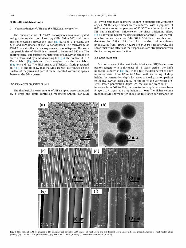
The microstructure of PSt-EA nanospheres was investigatedusing scanning electron microscopy (SEM, Sirion 200) and trans-mission electron microscopy (TEM). Fig. 4(a) and (b) presents theSEM and TEM images of PSt-EA nanospheres. The microscopy ofPSt-EA indicates that the nanospheres are monodisperse. The aver-age particle size of PSt-EA is estimated to be around 340 nm. Themorphological and surface characteristics of STF/Kevlar compositewere determined by SEM. According to Fig. 4, the surface of STF/Kevlar fabric (Fig. 4(d) and (f)) is rougher than the neat fabric(Fig. 4(c) and (e)). The SEM images of STF/Kevlar fabric presentedin Fig. 4(d) and (f) show that the STFs are well distributed on thesurface of the yarns and part of them is located within the spacesbetween the fabric yarns.
3.2. Rheological properties of STFs
The rheological measurements of STF samples were conductedby a stress and strain controlled rheometer (Anton-Paar MCR
Fig. 4. SEM (a) and TEM (b) images of PSt-EA spherical particles. SEM images of neat(400�), (d) STF/Kevlar composite (400�), (e) neat Kevlar fabric (2000�), (f) STF/Kevlar c
301) with cone-plate geometry (25 mm in diameter and 2� in coneangle). All the experiments were conducted with a gap size of0.05 mm at a room temperature of 25 �C. The volume fraction ofSTF has a significant influence on the shear thickening effect.Fig. 5 shows the typical rheological behavior of the STF. As the vol-ume fraction increases from 54%, 56% to 59%, the critical shear ratedecreases from 289 s�1, 63 s�1 to 19 s�1 and the maximum viscos-ity increases from 139 Pa s, 462 Pa s to 1496 Pa s, respectively. Theshear thickening effects of the suspensions are strengthened withthe increasing volume fraction.
3.3. Drop tower test
Stab resistance of the neat Kevlar fabrics and STF/Kevlar com-posites targets with a thickness of 15 layers against the knifeimpactor is shown in Fig. 6(a). In this test, the drop height of knifeimpactor varies from 0.2 m to 1.0 m. With increasing of dropheight, the penetration depth increases gradually. In comparisonto the neat Kevlar fabric and EG/Kevlar fabric, the STF/Kevlar pre-sents lower penetration depth. As the volume fraction of STFincreases from 54% to 59%, the penetration depth decreases from5 layers to 4 layers at a drop height of 1.0 m. The higher volumefraction of STF shows better knife stab resistance performance for
fabric and STF-treated fabric under different magnifications: (c) neat Kevlar fabricomposite (2000�).
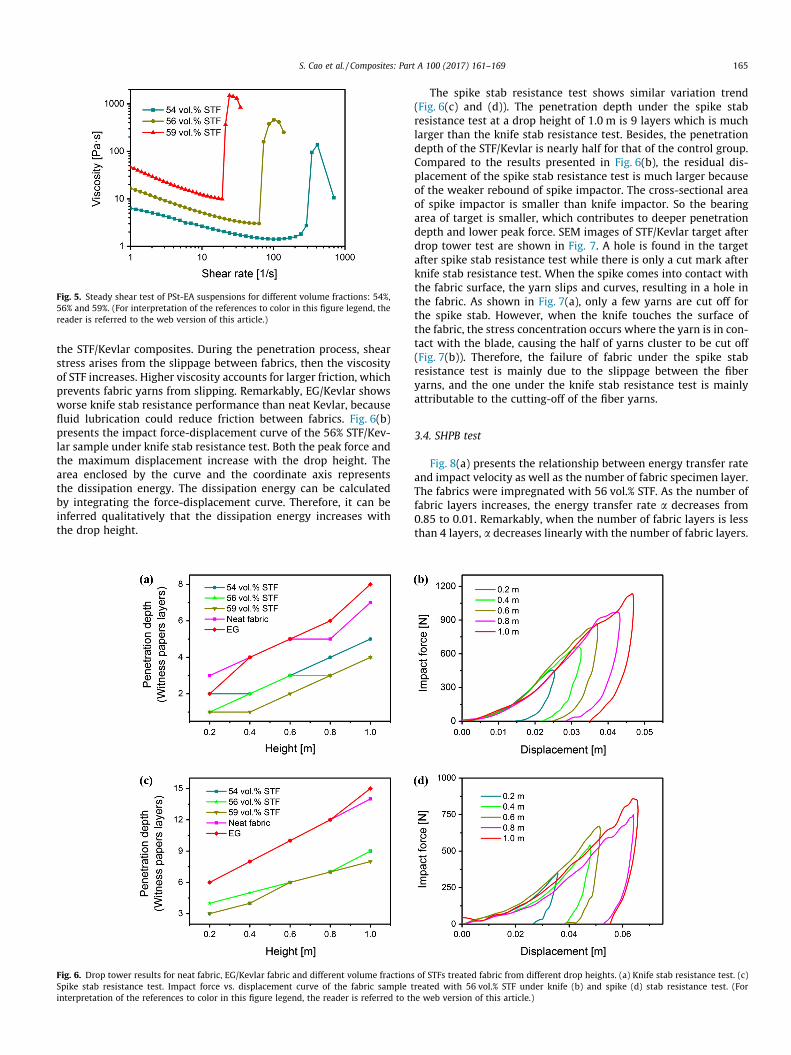
Fig. 5. Steady shear test of PSt-EA suspensions for different volume fractions: 54%,56% and 59%. (For interpretation of the references to color in this figure legend, thereader is referred to the web version of this article.)
S. Cao et al. / Composites: Part A 100 (2017) 161–169 165
the STF/Kevlar composites. During the penetration process, shearstress arises from the slippage between fabrics, then the viscosityof STF increases. Higher viscosity accounts for larger friction, whichprevents fabric yarns from slipping. Remarkably, EG/Kevlar showsworse knife stab resistance performance than neat Kevlar, becausefluid lubrication could reduce friction between fabrics. Fig. 6(b)presents the impact force-displacement curve of the 56% STF/Kev-lar sample under knife stab resistance test. Both the peak force andthe maximum displacement increase with the drop height. Thearea enclosed by the curve and the coordinate axis representsthe dissipation energy. The dissipation energy can be calculatedby integrating the force-displacement curve. Therefore, it can beinferred qualitatively that the dissipation energy increases withthe drop height.
Fig. 6. Drop tower results for neat fabric, EG/Kevlar fabric and different volume fractionsSpike stab resistance test. Impact force vs. displacement curve of the fabric sample tinterpretation of the references to color in this figure legend, the reader is referred to th
The spike stab resistance test shows similar variation trend(Fig. 6(c) and (d)). The penetration depth under the spike stabresistance test at a drop height of 1.0 m is 9 layers which is muchlarger than the knife stab resistance test. Besides, the penetrationdepth of the STF/Kevlar is nearly half for that of the control group.Compared to the results presented in Fig. 6(b), the residual dis-placement of the spike stab resistance test is much larger becauseof the weaker rebound of spike impactor. The cross-sectional areaof spike impactor is smaller than knife impactor. So the bearingarea of target is smaller, which contributes to deeper penetrationdepth and lower peak force. SEM images of STF/Kevlar target afterdrop tower test are shown in Fig. 7. A hole is found in the targetafter spike stab resistance test while there is only a cut mark afterknife stab resistance test. When the spike comes into contact withthe fabric surface, the yarn slips and curves, resulting in a hole inthe fabric. As shown in Fig. 7(a), only a few yarns are cut off forthe spike stab. However, when the knife touches the surface ofthe fabric, the stress concentration occurs where the yarn is in con-tact with the blade, causing the half of yarns cluster to be cut off(Fig. 7(b)). Therefore, the failure of fabric under the spike stabresistance test is mainly due to the slippage between the fiberyarns, and the one under the knife stab resistance test is mainlyattributable to the cutting-off of the fiber yarns.
3.4. SHPB test
Fig. 8(a) presents the relationship between energy transfer rateand impact velocity as well as the number of fabric specimen layer.The fabrics were impregnated with 56 vol.% STF. As the number offabric layers increases, the energy transfer rate a decreases from0.85 to 0.01. Remarkably, when the number of fabric layers is lessthan 4 layers, a decreases linearly with the number of fabric layers.
of STFs treated fabric from different drop heights. (a) Knife stab resistance test. (c)reated with 56 vol.% STF under knife (b) and spike (d) stab resistance test. (Fore web version of this article.)
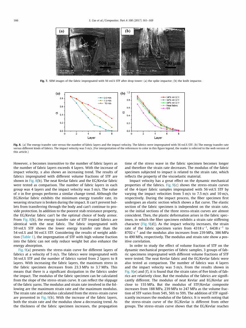
Fig. 7. SEM images of the fabric impregnated with 56 vol.% STF after drop tower: (a) the spike impactor; (b) the knife impactor.
Fig. 8. (a) The energy transfer rate versus the number of fabric layers and the impact velocity. The fabrics were impregnated with 56 vol.% STF. (b) The energy transfer rateversus different kinds of fabrics. The impact velocity was 5 m/s. (For interpretation of the references to color in this figure legend, the reader is referred to the web version ofthis article.)
166 S. Cao et al. / Composites: Part A 100 (2017) 161–169
However, a becomes insensitive to the number of fabric layers asthe number of fabric layers exceeds 4 layers. With the increase ofimpact velocity, a also shows an increasing trend. The results offabrics impregnated with different volume fractions of STF areshown in Fig. 8(b). The neat Kevlar fabric and the EG/Kevlar fabricwere tested as comparison. The number of fabric layers in eachgroup was 4 layers and the impact velocity was 5 m/s. The valueof a in five groups performs a similar change trend. Although theEG/Kevlar fabric exhibits the minimum energy transfer rate, itsweaving structure is broken during the impact. It can’t prevent bul-lets from transferring through the body and can’t continue to pro-vide protection. In addition to the poorest stab resistance property,the EG/Kevlar fabric can’t be the optimal choice of body armor.From Fig. 8(b), the energy transfer rate of STF treated fabrics areidentical with the neat fabric. The fabric impregnated with59 vol.% STF shows the lower energy transfer rate than the54 vol.% and 56 vol.% STF. Considering the results of weight addi-tion (Table 1), the impregnation of STF with high volume fractioninto the fabric can not only reduce weight but also enhance theenergy absorption.
Fig. 9(a) presents the stress-stain curve for different layers offabrics at a velocity of 5 m/s. The fabrics were impregnated with56 vol.% STF and the number of fabrics varied from 2 layers to 8layers. With increasing the fabric layers, the maximum stress inthe fabric specimen decreases from 23.3 MPa to 3.7 MPa. Thismeans that there is a significant dissipation in the fabrics underthe impact. The modulus of the fabric specimen can be calculatedfrom the slope of the stress-strain curve. It can reflect the slippageof the fabric yarns. The modulus and strain rate involved in the fol-lowing are the maximum strain rate and the maximum modulus.The strain rate and modulus calculated from the stress-strain curveare presented in Fig. 9(b). With the increase of the fabric layers,both the strain rate and the modulus show a decreasing trend. Asthe thickness of the fabric specimen increases, the propagation
time of the stress wave in the fabric specimen becomes longerand therefore the strain rate decreases. The modulus of the fabricspecimen subjected to impact is related to the strain rate, whichreflects the property of the viscoelastic material.
Impact velocity has a great effect on the dynamic mechanicalproperties of the fabrics. Fig. 9(c) shows the stress-strain curvesof the 4-layer fabric samples impregnated with 56 vol.% STF byvarying the impact velocities from 5 m/s to 7.5 m/s and 10 m/s,respectively. During the impact process, the fiber specimen firstundergoes an elastic section which shows a flat curve. The elasticsection of the fabric specimen is independent on the strain rate,so the initial sections of the three stress-strain curves are almostcoincident. Then, the plastic deformation arises in the fabric spec-imen, in which the fiber specimen exhibits a strain rate stiffeningcharacter (Fig. 9(d)). As the impact velocity increases, the strainrate of the fabric specimen varies from 4318 s�1, 6438 s�1 to8702 s�1 and the modulus also increases from 239 MPa, 386 MPato 490 MPa, respectively. The modulus and strain rate show a pos-itive correlation.
In order to study the effect of volume fraction of STF on thedynamic mechanical properties of fabric samples, 3 groups of fab-ric specimens impregnated with different volume fractions of STFwere tested. The neat Kevlar fabric and the EG/Kevlar fabric werealso tested as comparison. The number of fabrics was 4 layersand the impact velocity was 5 m/s. From the results shown inFig. 9(e) and (f), it is found that the strain rates of five kinds of fab-rics are relatively close. But the modulus of the fabrics are signifi-cantly different. The modulus of neat Kevlar and EG/Kevlar areclose to 155 MPa. But the modulus of STF/Kevlar compositeincreases from 188 MPa, 239 MPa to 247 MPa as the volume frac-tion of STF varies from 54%, 56% to 59%. The addition of STF signif-icantly increases the modulus of the fabrics. It is worth noting thatthe stress-strain curve of the EG/Kevlar is different from othergroups. The stress-strain curve shows that the EG/Kevlar reaches
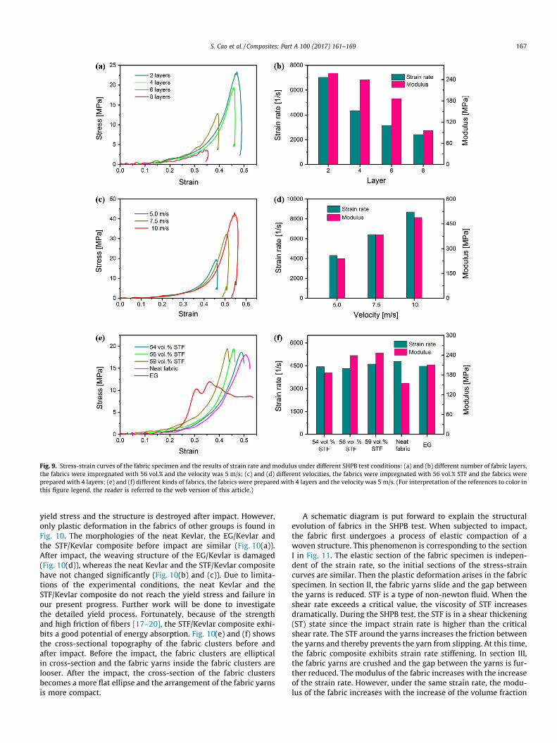
Fig. 9. Stress-strain curves of the fabric specimen and the results of strain rate and modulus under different SHPB test conditions: (a) and (b) different number of fabric layers,the fabrics were impregnated with 56 vol.% and the velocity was 5 m/s; (c) and (d) different velocities, the fabrics were impregnated with 56 vol.% STF and the fabrics wereprepared with 4 layers; (e) and (f) different kinds of fabrics, the fabrics were prepared with 4 layers and the velocity was 5 m/s. (For interpretation of the references to color inthis figure legend, the reader is referred to the web version of this article.)
S. Cao et al. / Composites: Part A 100 (2017) 161–169 167
yield stress and the structure is destroyed after impact. However,only plastic deformation in the fabrics of other groups is found inFig. 10. The morphologies of the neat Kevlar, the EG/Kevlar andthe STF/Kevlar composite before impact are similar (Fig. 10(a)).After impact, the weaving structure of the EG/Kevlar is damaged(Fig. 10(d)), whereas the neat Kevlar and the STF/Kevlar compositehave not changed significantly (Fig. 10(b) and (c)). Due to limita-tions of the experimental conditions, the neat Kevlar and theSTF/Kevlar composite do not reach the yield stress and failure inour present progress. Further work will be done to investigatethe detailed yield process. Fortunately, because of the strengthand high friction of fibers [17–20], the STF/Kevlar composite exhi-bits a good potential of energy absorption. Fig. 10(e) and (f) showsthe cross-sectional topography of the fabric clusters before andafter impact. Before the impact, the fabric clusters are ellipticalin cross-section and the fabric yarns inside the fabric clusters arelooser. After the impact, the cross-section of the fabric clustersbecomes a more flat ellipse and the arrangement of the fabric yarnsis more compact.
A schematic diagram is put forward to explain the structuralevolution of fabrics in the SHPB test. When subjected to impact,the fabric first undergoes a process of elastic compaction of awoven structure. This phenomenon is corresponding to the sectionI in Fig. 11. The elastic section of the fabric specimen is indepen-dent of the strain rate, so the initial sections of the stress-straincurves are similar. Then the plastic deformation arises in the fabricspecimen. In section II, the fabric yarns slide and the gap betweenthe yarns is reduced. STF is a type of non-newton fluid. When theshear rate exceeds a critical value, the viscosity of STF increasesdramatically. During the SHPB test, the STF is in a shear thickening(ST) state since the impact strain rate is higher than the criticalshear rate. The STF around the yarns increases the friction betweenthe yarns and thereby prevents the yarn from slipping. At this time,the fabric composite exhibits strain rate stiffening. In section III,the fabric yarns are crushed and the gap between the yarns is fur-ther reduced. The modulus of the fabric increases with the increaseof the strain rate. However, under the same strain rate, the modu-lus of the fabric increases with the increase of the volume fraction
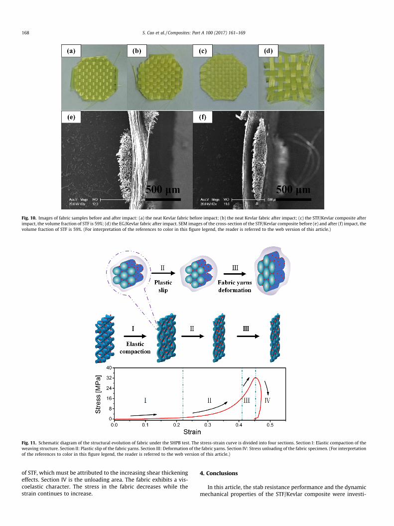
Fig. 10. Images of fabric samples before and after impact: (a) the neat Kevlar fabric before impact; (b) the neat Kevlar fabric after impact; (c) the STF/Kevlar composite afterimpact, the volume fraction of STF is 59%; (d) the EG/Kevlar fabric after impact. SEM images of the cross-section of the STF/Kevlar composite before (e) and after (f) impact, thevolume fraction of STF is 59%. (For interpretation of the references to color in this figure legend, the reader is referred to the web version of this article.)
Fig. 11. Schematic diagram of the structural evolution of fabric under the SHPB test. The stress-strain curve is divided into four sections. Section I: Elastic compaction of theweaving structure. Section II: Plastic slip of the fabric yarns. Section III: Deformation of the fabric yarns. Section IV: Stress unloading of the fabric specimen. (For interpretationof the references to color in this figure legend, the reader is referred to the web version of this article.)
168 S. Cao et al. / Composites: Part A 100 (2017) 161–169
of STF, which must be attributed to the increasing shear thickeningeffects. Section IV is the unloading area. The fabric exhibits a vis-coelastic character. The stress in the fabric decreases while thestrain continues to increase.
4. Conclusions
In this article, the stab resistance performance and the dynamicmechanical properties of the STF/Kevlar composite were investi-
S. Cao et al. / Composites: Part A 100 (2017) 161–169 169
gated. The STF enhanced the friction between fabric yarns due toits high viscosity under shear. The slippage of fabric yarns wasreduced and the stab resistance of fabric got significant enhance-ment. During the SHPB test, both the strain rate and the modulusof the STF/Kevlar composite showed an increasing trend with theincrease of impact velocity. Besides, the modulus of compositeincreased with the increasing of the volume fraction of STF. Theaddition of the STF and the increase of the fabric number reducedthe energy transfer rate. The energy absorption of the STF/Kevlarincreased with the volume fraction of the STF. It could be specu-lated that multilayer fabrics impregnated with high volume frac-tion of STF was the optimal choice for energy absorption.
Acknowledgements
Financial supports from the National Natural Science Founda-tion of China (Grant No. 11372301), the Fundamental ResearchFunds for the Central Universities (WK2480000002), and theStrategic Priority Research Program of the Chinese Academy ofSciences (Grant No. XDB22040502) are gratefully acknowledged.This work was also supported by Collaborative Innovation Centerof Suzhou Nano Science and Technology.
References
[1] Jacobs MJN, Van Dingenen JLJ. Ballistic protection mechanisms in personalarmour. J Mater Sci 2001;36(13):3137–42.
[2] Zhang GM, Batra RC, Zheng J. Effect of frame size, frame type, and clampingpressure on the ballistic performance of soft body armor. Compos B – Eng2008;39(3):476–89.
[3] Dong Z, Sun CT. Testing and modeling of yarn pull-out in plain woven Kevlarfabrics. Compos A – Appl Sci Manuf 2009;40(12):1863–9.
[4] Barnes HA. Shear-thickening (Dilatancy) in suspensions of nonaggregatingsolid particles dispersed in newtonian liquids. J Rheol 1989;33(2):329–66.
[5] Laun HM, Bung R, Schmidt F. Rheology of extremely shear thickening polymerdispersions (passively viscosity switching fluids). J Rheol 1991;35(6):999–1034.
[6] Zhang XZ, Li WH, Gong XL. Study on magnetorheological shear thickeningfluid. Smart Mater Struct 2008;17(1):015051.
[7] Ye F, Zhu W, Jiang WQ, Wang ZY, Chen Q, Gong XL, et al. Influence ofsurfactants on shear-thickening behavior in concentrated polymer dispersions.J Nanopart Res 2013;15(12):2122.
[8] Tan ZH, Zuo L, Li WH, Liu LS, Zhai PC. Dynamic response of symmetrical andasymmetrical sandwich plates with shear thickening fluid core subjected topenetration loading. Mater Des 2016;94:105–10.
[9] Decker MJ, Halbach CJ, Nam CH, Wagner NJ, Wetzel ED. Stab resistance of shearthickening fluid (STF)-treated fabrics. Compos Sci Technol 2007;67(3–4):565–78.
[10] Hassan TA, Rangari VK, Jeelani S. Synthesis, processing and characterization ofshear thickening fluid (STF) impregnated fabric composites. Mater Sci Eng A-Struct 2010;527(12):2892–9.
[11] Kang TJ, Hong KH, Yoo MR. Preparation and properties of fumed silica/Kevlarcomposite fabrics for application of stab resistant material. Fiber Polym2010;11(5):719–24.
[12] Yu KJ, Cao HJ, Qian K, Jiang LL, Li HS. Synthesis and stab resistance of shearthickening fluid (STF) impregnated glass fabric composites. Fibres Text EastEur 2012;20(6A):126–8.
[13] Majumdar A, Butola BS, Srivastava A. An analysis of deformation and energyabsorption modes of shear thickening fluid treated Kevlar fabrics as soft bodyarmour materials. Mater Des 2013;51:148–53.
[14] Sun LL, Xiong DS, Xu CY. Application of shear thickening fluid in ultra highmolecular weight polyethylene fabric. J Appl Polym Sci 2013;129(4):1922–8.
[15] Feng XY, Li SK, Wang Y, Wang YC, Liu JX. Effects of different silica particles onquasi-static stab resistant properties of fabrics impregnated with shearthickening fluids. Mater Des 2014;64:456–61.
[16] Firouzi D, Foucher DA, Bougherara H. Nylon-coated ultra high molecularweight polyethylene fabric for enhanced penetration resistance. J Appl PolymSci 2014;131(11):169–72.
[17] Gong XL, Xu YL, Zhu W, Xuan SH, Jiang WF, Jiang WQ. Study of the knife staband puncture-resistant performance for shear thickening fluid enhancedfabric. J Compos Mater 2014;48(6):641–57.
[18] Hasanzadeh M, Mottaghitalab V. The role of shear-thickening fluids (STFs) inballistic and stab-resistance improvement of flexible armor. J Mater EngPerform 2014;23(4):1182–96.
[19] Li W, Xiong DS, Zhao XD, Sun LL, Liu J. Dynamic stab resistance of ultra-highmolecular weight polyethylene fabric impregnated with shear thickeningfluid. Mater Des 2016;102:162–7.
[20] Gürgen S, Kus�han MC. The stab resistance of fabrics impregnated with shearthickening fluids including various particle size of additives. Compos A – ApplSci Manuf 2017;94:50–60.
[21] Kalman DP, Merrill RL, Wagner NJ, Wetzel ED. Effect of particle hardness onthe penetration behavior of fabrics intercalated with dry particles andconcentrated particle-fluid suspensions. ACS Appl Mater Interfaces 2009;1(11):2602–12.
[22] Bilisik K. Properties of yarn pull-out in para-aramid fabric structure andanalysis by statistical model. Compos A – Appl Sci Manuf 2011;42(12):1930–42.
[23] Zhu D, Soranakom C, Mobasher B, Rajan SD. Experimental study and modelingof single yarn pull-out behavior of kevlar� 49 fabric. Compos A – Appl SciManuf 2011;42(7):868–79.
[24] Hasanzadeh M, Mottaghitalab V, Babaei H, Rezaei M. The influence of carbonnanotubes on quasi-static puncture resistance and yarn pull-out behavior ofshear-thickening fluids (STFs) impregnated woven fabrics. Compos A – ApplSci Manuf 2016;88:263–71.
[25] Lee YS, Wetzel ED, Wagner NJ. The ballistic impact characteristics of Kevlar (R)woven fabrics impregnated with a colloidal shear thickening fluid. J Mater Sci2003;38(13):2825–33.
[26] Kang TJ, Kim CY, Hong KH. Rheological behavior of concentrated silicasuspension and its application to soft armor. J Appl Polym Sci 2012;124(2):1534–41.
[27] Kordani N, Vanini AS. Optimizing the ethanol content of shear thickeningfluid/fabric composites under impact loading. J Mech Sci Technol 2014;28(2):663–7.
[28] Park Y, Kim Y, Baluch AH, Kim CG. Empirical study of the high velocity impactenergy absorption characteristics of shear thickening fluid (STF) impregnatedKevlar fabric. Int J Impact Eng 2014;72:67–74.
[29] Haro EE, Szpunar JA, Odeshi AG. Ballistic impact response of laminated hybridmaterials made of 5086-H32 aluminum alloy, epoxy and Kevlar (R) fabricsimpregnated with shear thickening fluid. Compos A – Appl Sci Manuf2016;87:54–65.
[30] Lu ZQ, Jing XY, Sun BZ, Gu BH. Compressive behaviors of warp-knitted spacerfabrics impregnated with shear thickening fluid. Compos Sci Technol2013;88:184–9.
[31] Haris A, Lee HP, Tay TE, Tan VBC. Shear thickening fluid impregnated ballisticfabric composites for shock wave mitigation. Int J Impact Eng2015;80:143–51.
[32] NaW, Ahn H, Han S, Harrison P, Park JK, Jeong E, et al. Shear behavior of a shearthickening fluid-impregnated aramid fabrics at high shear rate. Compos B –Eng 2016;97:162–75.
[33] Lu ZQ, Wu LW, Gu BH, Sun BZ. Numerical simulation of the impact behaviors ofshear thickening fluid impregnated warp-knitted spacer fabric. Compos B –Eng 2015;69:191–200.
[34] Park Y, Kim Y, Baluch AH, Kim CG. Numerical simulation and empiricalcomparison of the high velocity impact of STF impregnated Kevlar fabric usingfriction effects. Compos Struct 2015;125:520–9.
[35] Lee BW, Kim CG. Computational analysis of shear thickening fluid impregnatedfabrics subjected to ballistic impacts. Adv Compos Mater 2012;21(2):177–92.
[36] Wu XF, Ghoshal G, Kartashov M, Aslan Z, Turner JA, Dzenis YA. Experimentalcharacterization of the impact-damage tolerance of a cross-ply graphite-fiber/epoxy laminate. Polym Compos 2008;29(5):534–43.
[37] Lim AS, Lopatnikov SL, Wagner NJ, Gillespie JW. Investigating the transientresponse of a shear thickening fluid using the split Hopkinson pressure bartechnique. Rheol Acta 2010;49(8):879–90.
[38] Lim AS, Lopatnikov SL, Wagner NJ, Gillespie JW. An experimental investigationinto the kinematics of a concentrated hard-sphere colloidal suspension duringHopkinson bar evaluation at high stresses. J Non-Newton Fluid 2010;165(19–20):1342–50.
[39] Lomakin EV, Mossakovsky PA, Bragov AM, Lomunov AK, Konstantinov AY,Kolotnikov ME, et al. Investigation of impact resistance of multilayered wovencomposite barrier impregnated with the shear thickening fluid. Arch ApplMech 2011;81(12):2007–20.
[40] Jiang WF, Gong XL, Xuan SH, Jiang WQ, Ye F, Li XF, et al. Stress pulseattenuation in shear thickening fluid. Appl Phys Lett 2013;102(10):101901.
[41] Liao GJ, Gong XL, Xuan SH. Magnetic field-induced compressive property ofmagnetorheological elastomer under high strain rate. Ind Eng Chem Res2013;52(25):8445–53.
[42] Woo SC, Kim TW. High-strain-rate impact in Kevlar-woven composites andfracture analysis using acoustic emission. Compos B – Eng 2014;60:125–36.
[43] Wang YP, Wang S, Xu CH, Xuan SH, Jiang WQ, Gong XL. Dynamic behavior ofmagnetically responsive shear-stiffening gel under high strain rate. ComposSci Technol 2016;127:169–76.
[44] Parmley LF, Manion WC, Mattingly TW. Nonpenetrating traumatic injury ofthe heart. Circulation 1958;18(3):371–96.
[45] Roberts JC, Merkle AC, Biermann PJ, Ward EE, Carkhuff BG, Cain RP, et al.Computational and experimental models of the human torso for non-penetrating ballistic impact. J Biomech 2007;40(1):125–36.
[46] Roberts JC, O’connor JV, Ward EE. Modeling the effect of nonpenetratingballistic impact as a means of detecting behind-armor blunt trauma. J TraumaAcute Care Surg 2005;58(6):1241–51.