Embed Size (px)
Citation preview
41-759.3C
2
AR Auxiliary Relay High Speed, High Threshold
the magnetic core upon energizing of the switch.When the switch closes, the moving contacts bridgetwo stationary contacts, completing the trip circuit.Also during this operation two fingers on the arma-ture deflect a spring located on the front of theswitch, allowing the operation indicator target todrop. The target is reset from the outside of the caseby a push-rod located at the bottom of the case.
The front spring, in addition to holding the target, pro-vides restraint for the armature and thus controls thepickup value of the switch.
The ICS unit is commonly used to provide a seal inaround the main protective relay contacts relievingthem of carrying heavy duty trip currents.
When ac current is necessary in a control trip circuit,some chattering can be observed and the ICS unitcan be replaced by an ACS unit.
Operating speed of the ICS unit at two times pickupis 10 to 16 ms.
3.0 CHARACTERISTICS
The relay operates in 4 milliseconds for an energy in-put of 10 watts. The reset time is typically 16 millisec-onds.
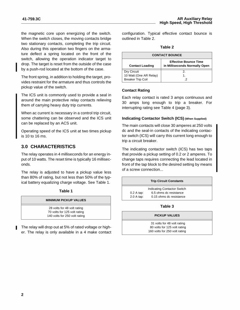
The relay is adjusted to have a pickup value lessthan 80% of rating, but not less than 50% of the typ-ical battery equalizing charge voltage. See Table 1.
The relay will drop out at 5% of rated voltage or high-er. The relay is only available in a 4 make contact
configuration. Typical effective contact bounce isoutlined in Table 2.
Contact Rating
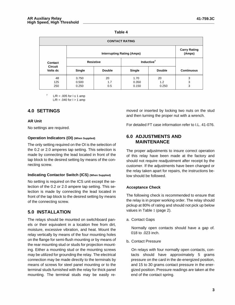
Each relay contact is rated 3 amps continuous and30 amps long enough to trip a breaker. Forinterrupting rating see Table 4 (page 3).
Indicating Contactor Switch (ICS) (When Supplied)
The main contacts will close 30 amperes at 250 voltsdc and the seal-in contacts of the indicating contac-tor switch (ICS) will carry this current long enough totrip a circuit breaker.
The indicating contactor switch (ICS) has two tapsthat provide a pickup setting of 0.2 or 2 amperes. Tochange taps requires connecting the lead located infront of the tap block to the desired setting by meansof a screw connection...
Table 1
MINIMUM PICKUP VALUES
28 volts for 48 volt rating 70 volts for 125 volt rating 140 volts for 250 volt rating
Table 2
CONTACT BOUNCE
Contact LoadingEffective Bounce Time
in Milliseconds Normally Open
Dry Circuit 10 Watt (One AR Relay) Breaker Trip Coil
2.1.
.2
Trip Circuit Constants
Indicating Contactor Switch0.2 A tap: 6.5 ohms dc resistance2.0 A tap: 0.15 ohms dc resistance
Table 3
PICKUP VALUES
31 volts for 48 volt rating80 volts for 125 volt rating
160 volts for 250 volt rating
41-759.3C
3
AR Auxiliary RelayHigh Speed, High Threshold
Table 4
CONTACT RATING
ContactCircuit
Volts dc
Interrupting Rating (Amps)Carry Rating
(Amps)
Resistive Inductive†
ContinuousSingle Double Single Double
48125250
3.7500.5000.250
201.70.5
1.700.3500.150
201.20.250
333
† L/R = .005 for I ≤ 1 ampL/R = .040 for I > 1 amp
4.0 SETTINGS
AR Unit
No settings are required.
Operation Indicators (OI) (When Supplied)
The only setting required on the OI is the selection ofthe 0.2 or 2.0 amperes tap setting. This selection ismade by connecting the lead located in front of thetap block to the desired setting by means of the con-necting screw.
Indicating Contactor Switch (ICS) (When Supplied)
No setting is required on the ICS unit except the se-lection of the 0.2 or 2.0 ampere tap setting. This se-lection is made by connecting the lead located infront of the tap block to the desired setting by meansof the connecting screw.
5.0 INSTALLATION
The relays should be mounted on switchboard pan-els or their equivalent in a location free from dirt,moisture, excessive vibration, and heat. Mount therelay vertically by means of the four mounting holeson the flange for semi-flush mounting or by means ofthe rear mounting stud or studs for projection mount-ing. Either a mounting stud or the mounting screwsmay be utilized for grounding the relay. The electricalconnection may be made directly to the terminals bymeans of screws for steel panel mounting or to theterminal studs furnished with the relay for thick panelmounting. The terminal studs may be easily re-
moved or inserted by locking two nuts on the studand then turning the proper nut with a wrench.
For detailed FT case information refer to I.L. 41-076.
6.0 ADJUSTMENTS AND MAINTENANCE
The proper adjustments to insure correct operationof this relay have been made at the factory andshould not require readjustment after receipt by thecustomer. If the adjustments have been changed orthe relay taken apart for repairs, the instructions be-low should be followed.
Acceptance Check
The following check is recommended to ensure thatthe relay is in proper working order. The relay shouldpickup at 80% of rating and should not pick up belowvalues in Table 1 (page 2).
a. Contact Gaps
Normally open contacts should have a gap of.018 to .023 inch.
b. Contact Pressure
On relays with four normally open contacts, con-tacts should have approximately 5 gramspressure on the card in the de-energized position,and 15 to 30 grams contact pressure in the ener-gized position. Pressure readings are taken at theend of the contact spring.
41-759.3C
4
AR Auxiliary Relay High Speed, High Threshold
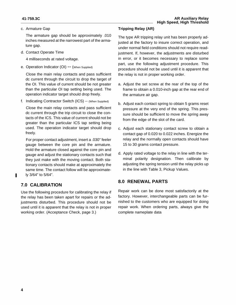
c. Armature Gap
The armature gap should be approximately .010inches measured at the narrowest part of the arma-ture gap.
d. Contact Operate Time
4 milliseconds at rated voltage.
e. Operation Indicator (OI) -- (When Supplied)
Close the main relay contacts and pass sufficientdc current through the circuit to drop the target ofthe OI. This value of current should be not greaterthan the particular OI tap setting being used. Theoperation indicator target should drop freely.
f. Indicating Contractor Switch (ICS) -- (When Supplied)
Close the main relay contacts and pass sufficientdc current through the trip circuit to close the con-tacts of the ICS. This value of current should not begreater than the particular ICS tap setting beingused. The operation indicator target should dropfreely.
For proper contact adjustment, insert a .030" feelergauge between the core pin and the armature.Hold the armature closed against the core pin andgauge and adjust the stationary contacts such thatthey just make with the moving contact. Both sta-tionary contacts should make at approximately thesame time. The contact follow will be approximate-ly 3/64” to 5/64”.
7.0 CALIBRATION
Use the following procedure for calibrating the relay ifthe relay has been taken apart for repairs or the ad-justments disturbed. This procedure should not beused until it is apparent that the relay is not in properworking order. (Acceptance Check, page 3.)
Tripping Relay (AR)
The type AR tripping relay unit has been properly ad-justed at the factory to insure correct operation, andunder normal field conditions should not require read-justment. If, however, the adjustments are disturbedin error, or it becomes necessary to replace somepart, use the following adjustment procedure. Thisprocedure should not be used until it is apparent thatthe relay is not in proper working order.
a. Adjust the set screw at the rear of the top of theframe to obtain a 0.010-inch gap at the rear end ofthe armature air gap.
b. Adjust each contact spring to obtain 5 grams resetpressure at the very end of the spring. This pres-sure should be sufficient to move the spring awayfrom the edge of the slot of the card.
c. Adjust each stationary contact screw to obtain acontact gap of 0.020 to 0.022 inches. Energize therelay and the normally open contacts should have15 to 30 grams contact pressure.
d. Apply rated voltage to the relay in line with the ter-minal polarity designation. Then calibrate byadjusting the spring tension until the relay picks upin the line with Table 3, Pickup Values.
8.0 RENEWAL PARTS
Repair work can be done most satisfactorily at thefactory. However, interchangeable parts can be fur-nished to the customers who are equipped for doingrepair work. When ordering parts, always give thecomplete nameplate data

41-759.3C
5
AR Auxiliary RelayHigh Speed, High Threshold
NOTES
41-759.3C
6
AR Auxiliary Relay High Speed, High Threshold
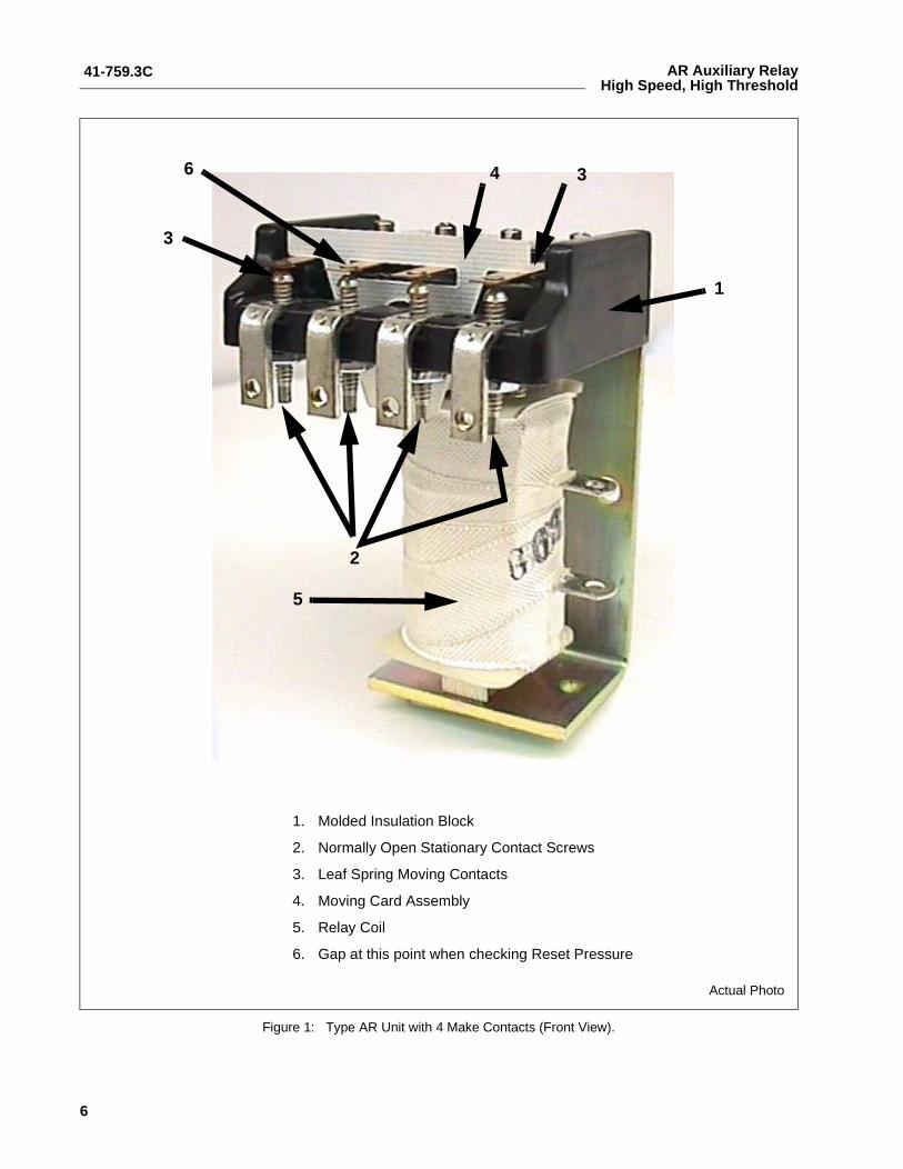
Figure 1: Type AR Unit with 4 Make Contacts (Front View).
1. Molded Insulation Block
2. Normally Open Stationary Contact Screws
3. Leaf Spring Moving Contacts
4. Moving Card Assembly
5. Relay Coil
6. Gap at this point when checking Reset Pressure
1
346
3
5
2
Actual Photo
41-759.3C
7
AR Auxiliary RelayHigh Speed, High Threshold
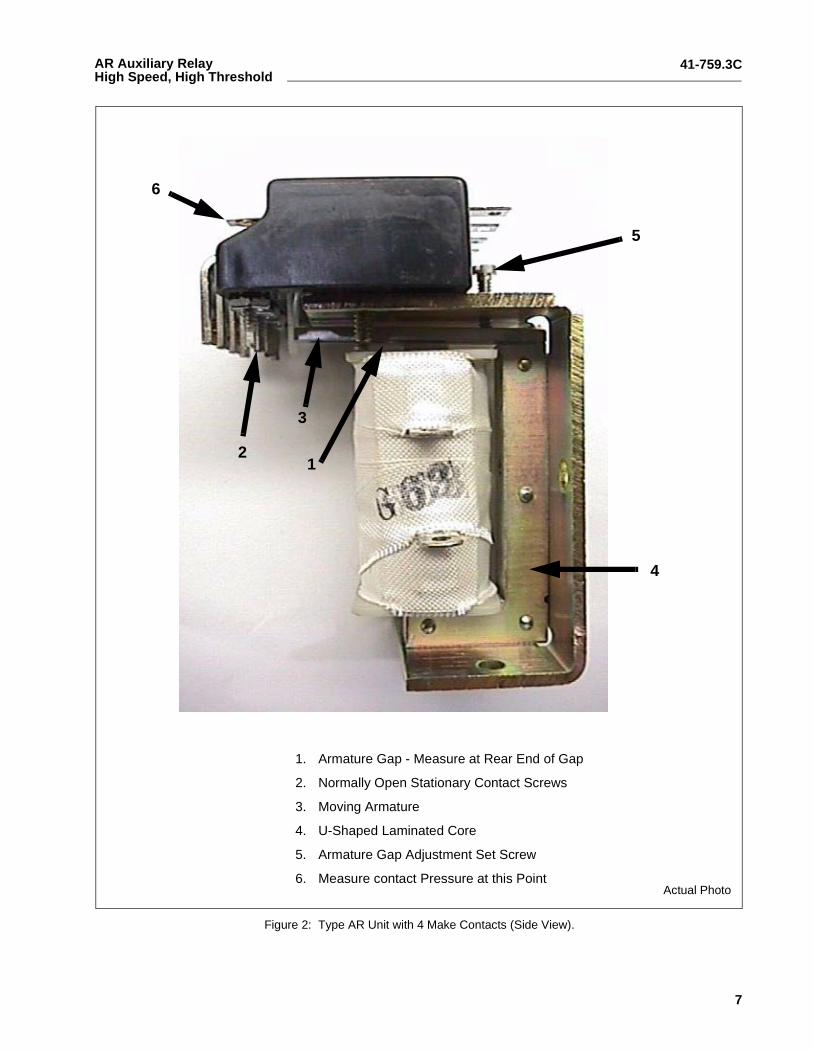
Figure 2: Type AR Unit with 4 Make Contacts (Side View).
1. Armature Gap - Measure at Rear End of Gap
2. Normally Open Stationary Contact Screws
3. Moving Armature
4. U-Shaped Laminated Core
5. Armature Gap Adjustment Set Screw
6. Measure contact Pressure at this Point
12
3
4
5
6
Actual Photo
41-759.3C
8
AR Auxiliary Relay High Speed, High Threshold
3500
A85
3512
A30
Fig
ure
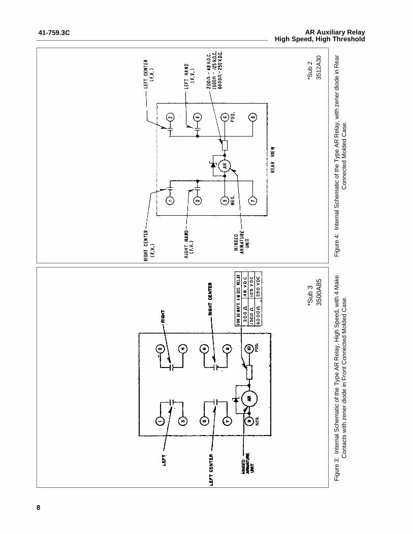
3:In
tern
al S
chem
atic
of t
he T
ype
AR
Rel
ay, H
igh
Spe
ed, w
ith 4
Mak
e C
onta
cts
with
zen
er d
iode
in F
ront
Con
nect
ed M
olde
d C
ase.
Fig
ure
4:In
tern
al S
chem
atic
of t
he T
ype
AR
Rel
ay, w
ith z
ener
dio
de in
Rea
r C
onne
cted
Mol
ded
Cas
e.
*Sub
3*S
ub 2
41-759.3C
9
AR Auxiliary RelayHigh Speed, High Threshold
Fig
ure
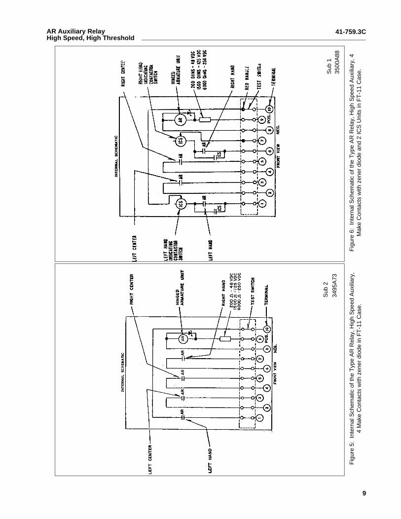
5:In
tern
al S
chem
atic
of t
he T
ype
AR
Rel
ay, H
igh
Spe
ed A
uxili
ary,
4
Mak
e C
onta
cts
with
zen
er d
iode
in F
T-1
1 C
ase.
Fig
ure
6:In
tern
al S
chem
atic
of t
he T
ype
AR
Rel
ay, H
igh
Spe
ed A
uxili
ary,
4
Mak
e C
onta
cts
with
zen
er d
iode
and
2 IC
S U
nits
in F
T-1
1 C
ase.
3495
A73
3500
A88
Sub
2S
ub 1
41-759.3C
10
AR Auxiliary Relay High Speed, High Threshold
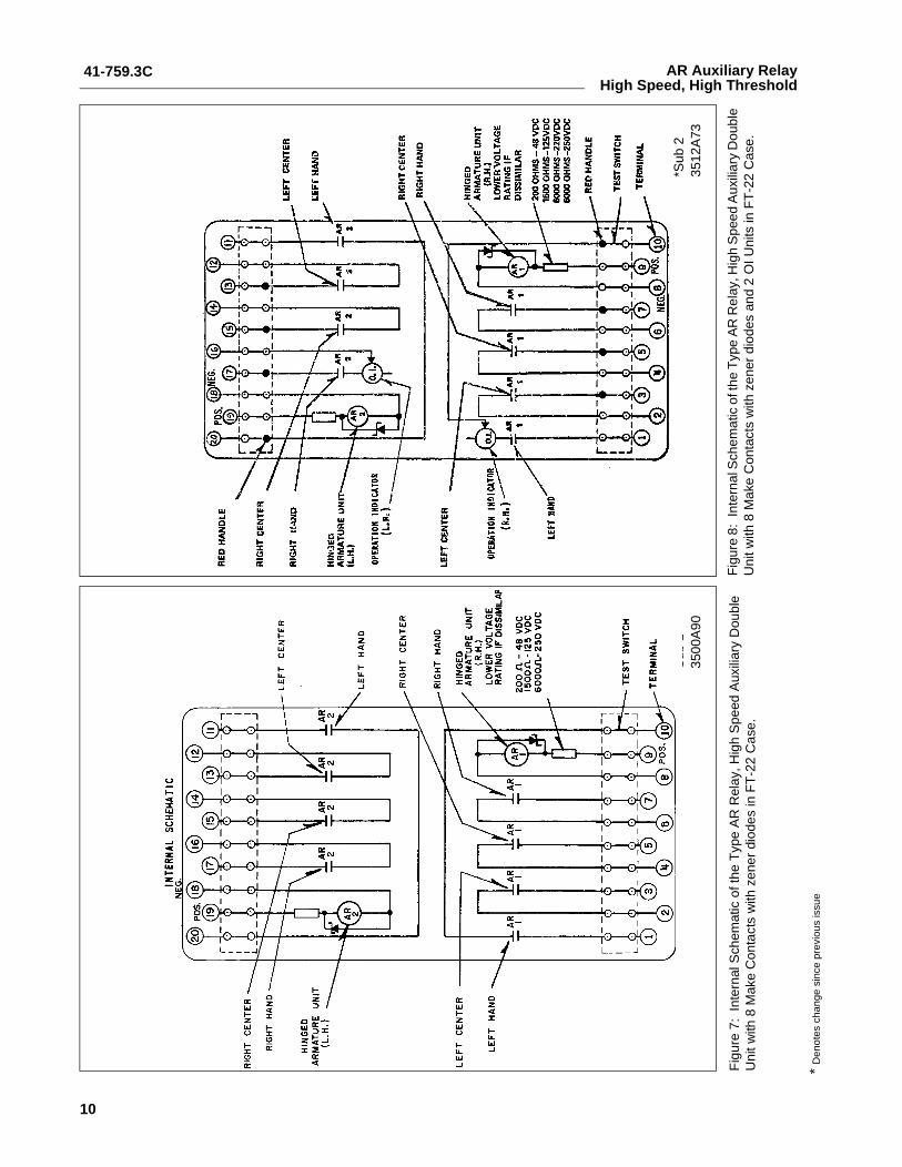
Fig
ure
7:In
tern
al S
chem
atic
of t
he T
ype
AR
Rel
ay, H
igh
Spe
ed A
uxili
ary
Dou
ble
Uni
t with
8 M
ake
Con
tact
s w
ith z
ener
dio
des
in F
T-2
2 C
ase.
Fig
ure
8:In
tern
al S
chem
atic
of t
he T
ype
AR
Rel
ay, H
igh
Spe
ed A
uxili
ary
Dou
ble
Uni
t with
8 M
ake
Con
tact
s w
ith z
ener
dio
des
and
2 O
I Uni
ts in
FT
-22
Cas
e.
3500
A90
3512
A73
Sub
1*S
ub 2
*D
enot
es c
hang
e si
nce
prev
ious
issu
e
41-759.3C
11
AR Auxiliary RelayHigh Speed, High Threshold
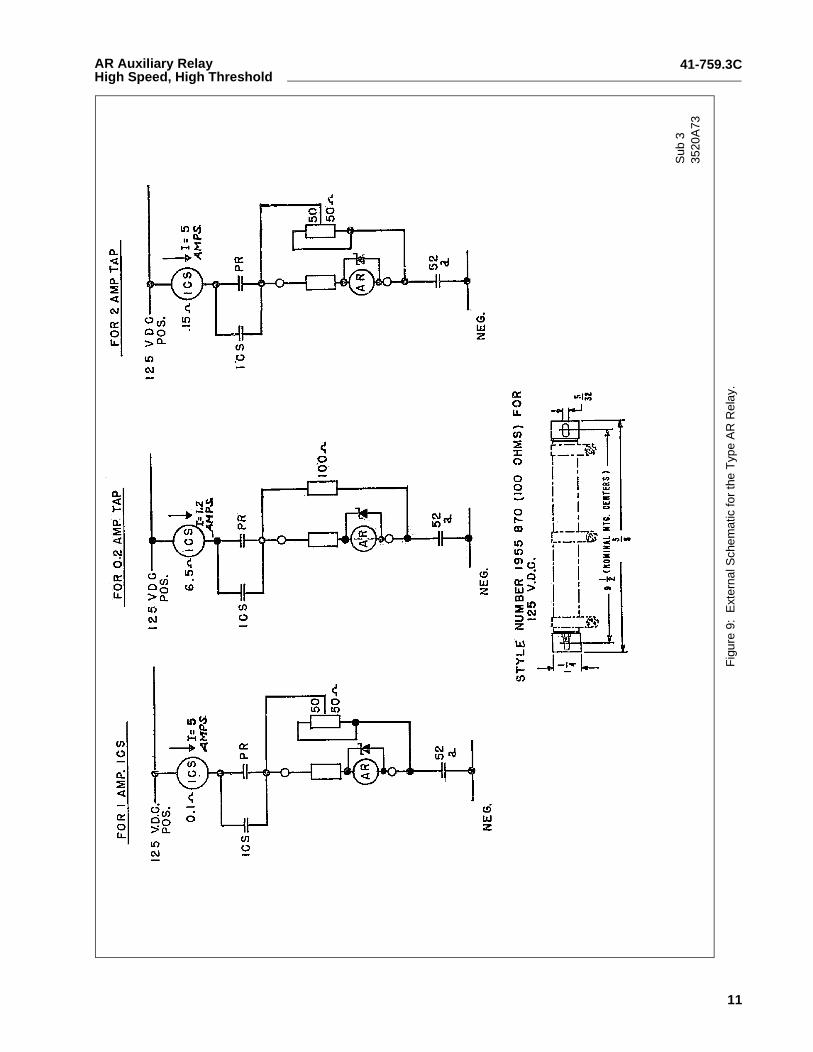
Fig
ure
9:E
xter
nal S
chem
atic
for
the
Typ
e A
R R
elay
.
3520
A73
Sub
3
41-759.3C
12
AR Auxiliary Relay High Speed, High Threshold
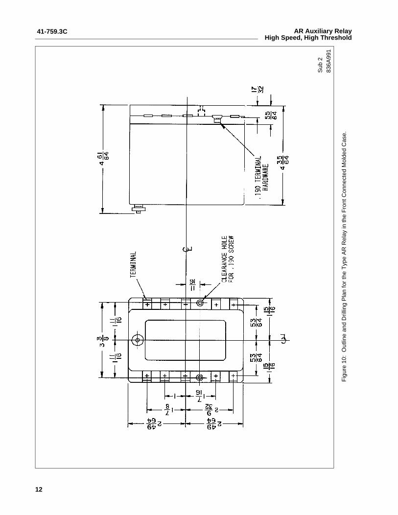
Fig
ure
10:
Out
line
and
Dril
ling
Pla
n fo
r th
e T
ype
AR
Rel
ay in
the
Fro
nt C
onne
cted
Mol
ded
Cas
e.
836A
991
Sub
2
41-759.3C
13
AR Auxiliary RelayHigh Speed, High Threshold
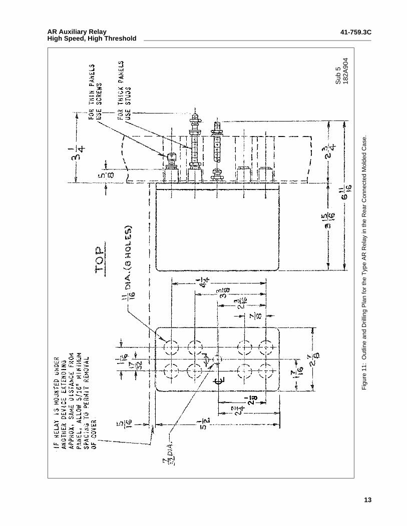
Fig
ure
11:
Out
line
and
Dril
ling
Pla
n fo
r th
e T
ype
AR
Rel
ay in
the
Rea
r C
onne
cted
Mol
ded
Cas
e.
Sub
518
2A90
4
41-759.3C
14
AR Auxiliary Relay High Speed, High Threshold
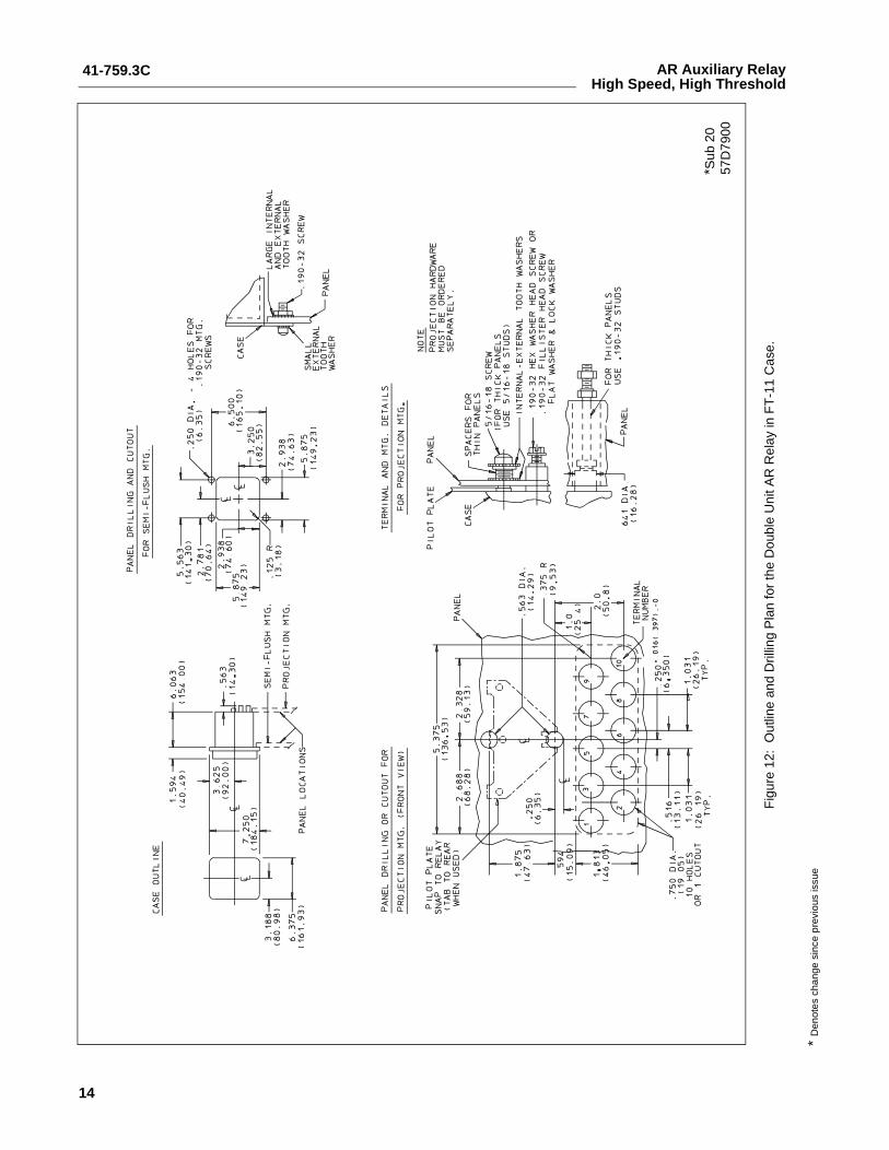
Fig
ure
12:
Out
line
and
Dril
ling
Pla
n fo
r th
e D
oubl
e U
nit A
R R
elay
in F
T-1
1 C
ase.
*Sub
20
57D
7900
*D
enot
es c
hang
e si
nce
prev
ious
issu
e
41-759.3C
15
AR Auxiliary RelayHigh Speed, High Threshold
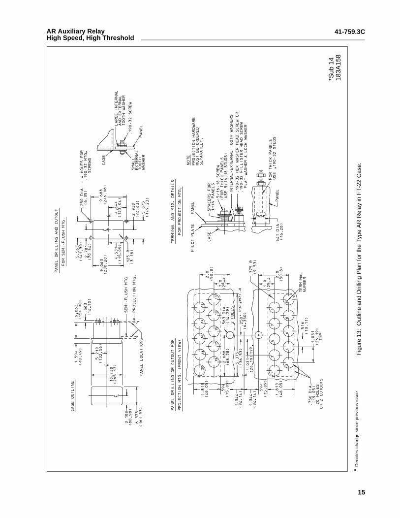
Fig
ure
13:
Out
line
and
Dril
ling
Pla
n fo
r th
e T
ype
AR
Rel
ay in
FT
-22
Cas
e.
*Sub
14
183A
158
*D
enot
es c
hang
e si
nce
prev
ious
issu
e
ABB Inc.4300 Coral Ridge DriveCoral Springs, Florida 33065Telephone: +1 954-752-6700Fax: +1 954-345-5329www.abb.com/substation automation
IL 4
1-75
9.3
- Rev
isio
n C
ABB