Embed Size (px)
Citation preview
170 Philips tech. Rev. 34, 170-179, 1974, No. 7
High-speed solid-rotor induction motors
H. G. Lakerveld
Introduetion
A two-pole induction motor that runs from the a.c.mains has a speed of slightly less than 50 revolutionsper second (i.e. 3000 revolutions per minute) [11. Thespeed of motors with four, six or more poles is lower bya corresponding factor. Some applications, however,require much higher speeds; filament-coiling machinesrequire speeds up to 30000 rev/min, ultracentrifugesfor uranium enrichment spin at 60000 rev/ruin, andnylon-thread spinning machines require speeds as highas 100 000 rev/min. Speeds as high as this are best ob-tained with a direct drive from high-speed motorssupplied by a 'high-frequency' a.c. supply. Otherexamples are high-speed hand tools (grinding machines,25000 to 60 000 rev/min) and machines for processingdiamond dies (80000 rev/ruin). In vacuum cleaners,which require speeds of up to 20 000 rev/min, the driveis provided by an a.c. commutator motor.
Apart from the technical requirements of the appli-cation, there is another argument for using high-speedmotors as the drive, and this is the improvement in thepower-to-weight ratio of the motor. The torque thatcan be delivered is limited by the dimensions of themotor and by the scope for dissipating the heat gen-erated; the delivered power, however, is determined bythe product of torque and speed, and the power limitis only reached when the mechanical construction ofthe motor does not allow a higher speed. Increasingthe power-to-weight ratio by raising the speed isof particular advantage when weight is an impor-tant consideration, as it is in aeronautics and spacetechnology and also in some electrical automo-biles, as yet in prototype; in many cases the advan-tages of a high-speed motor are not cancelled out byhaving to use a reduction gear.
High-speed electric motors can be of either the syn-chronous or the asynchronous type. In applicationswhere a synchronous motor is required a hysteresis mo-tor or a reluctance motor (with starting cage) is usuallysuitable; a motor with a permanent-magnet rotor is notso suitable because many magnetic materials cannotwithstand very high centrifugal forces. If some varia-tion of speed with load is permissible, the obvious solu-tion is an induction motor. This is the type we shall beconcerned with in this article, which describes an in-
Ir H. G. Lakerveld is with Philips Research Laboratories, Eind-hoven.
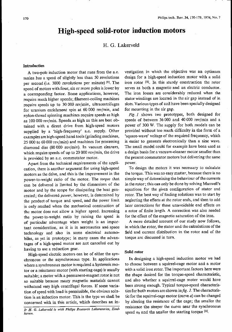
vestigation in which the objective was an optimumdesign for a high-speed induction motor with a solidiron rotor [21. In this sturdy construction the rotorserves as both a magnetic and an electric conductor.The iron losses are considerably reduced when thestator windings are located in the air gap instead of inslots. Various types of coil have been specially designedfor mounting in the air gap.Fig. 1 .shows two prototypes, both designed for
speeds of between 36000 and 40000 rev/ruin and apower of 300 W. The supply for both models can beprovided without too much difficulty in the form of a'square-wave' voltage of the required frequency, whichis easier to generate electronically than a sine wave.The small model could for example have been used asa design basis for a vacuum-cleaner motor smaller thanthe present commutator motors but delivering the samepower.
To design the motors it was necessary to calculatethe torque. This was no easy matter, because there is nosimple way of determining the behaviour ofthe currentsin the rotor; this can only be done by solving Maxwell'sequations for the given configuration of stator androtor. The best way offinding solutions was to start byneglecting the effects at the rotor ends, and then to addlater corrections for these unavoidable end effects ona rotor of finite length. A correction was also neededfor the effect of the magnetic saturation of the iron.
A more detailed account of our study now follows,in which the rotor, the stator and the calculations ofthefield and current distribution in the rotor and of thetorque are discussed in turn.
Solid rotor
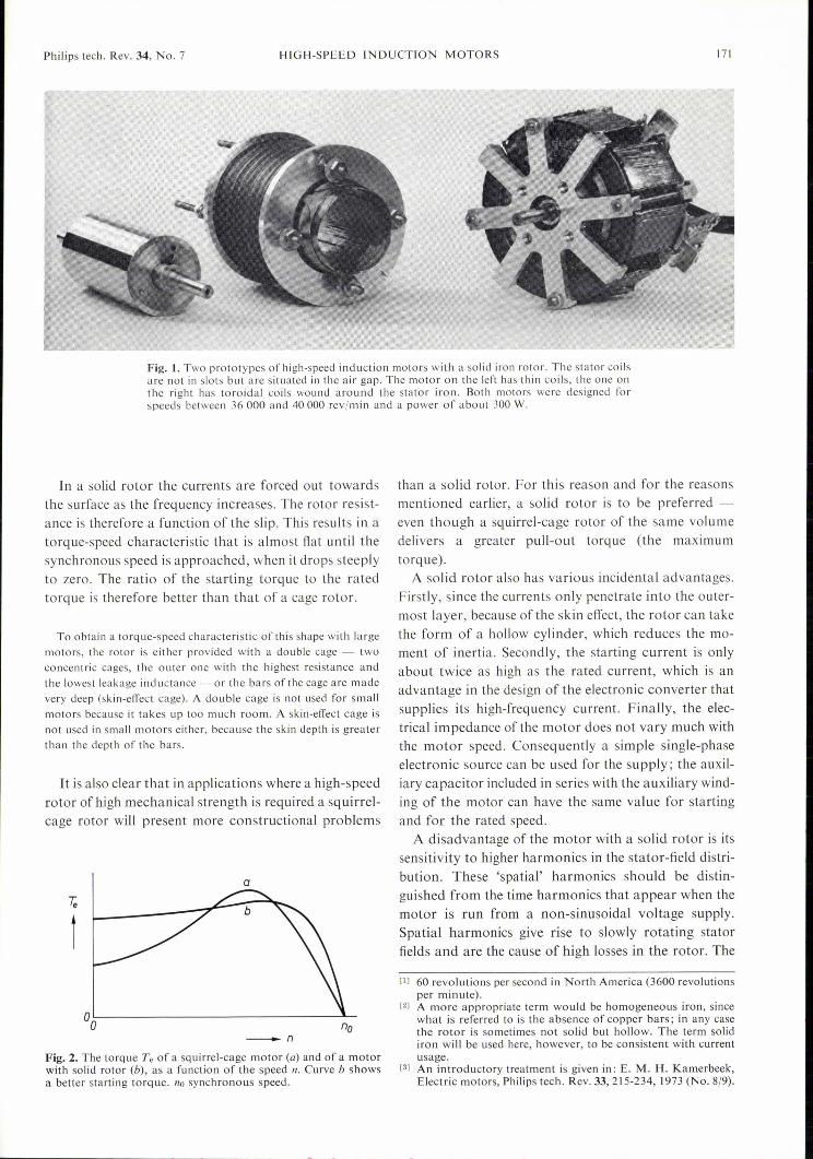
In designing a high-speed induction motor we hadto choose between a squirrel-cage motor and a motorwith a solid iron rotor. The important factors here werethe shape desired for the torque-speed characteristic,and also whether a squirrel-cage motor would havebeen strong enough. Typical torque-speed characteris-tics for both motors are shown infig. 2. The characteris-tic for the squirrel-cage motor (curve a) can be changedby altering the resistance of the cage; the smaller theresistance the steeper the curve near the synchronousspeed no and the smaller the starting torque [31.
Philips tech. Rev. 34, No. 7 HIGH-SPEED INDUCTION MOTORS 171
Fig. 1. Two prototypes of high-speed induction motors with a solid iron rotor. The stator coilsare not in slots but are situated in the air gap. The motor on the left has thin coils, the one onthe right has toroidal coils wound around the stator iron. Both motors were designed forspeeds between 36000 and 40000 rev/ruin and a power of about 300 W.
In a solid rotor the currents are forced out towardsthe surface as the frequency increases. The rotor resist-ance is therefore a function of the slip. This results in atorque-speed characteristic that is almost flat until thesynchronous speed is approached, when it drops steeplyto zero. The ratio of the starting torque to the ratedtorque is therefore better than that of a cage rotor.
To obtain a torque-speed characteristic ofthis shape with largemotors, the rotor is either provided with a double cage - twoconcentric cages, the outer one with the highest resistance andthe lowest leakage inductance - or the bars of the cage are madevery deep (skin-effect cage). A double cage is not used for smallmotors because it takes up too much room. A skin-effect cage isnot used in small motors either, because the skin depth is greaterthan the depth of the bars.
It is also clear that in applications where a high-speedrotor of high mechanical strength is required a sq uirrel-cage rotor will present more constructional problems
a
t
_nFig. 2. The torque Te of a squirrel-cage motor (a) and of a motorwith solid rotor (b), as a function of the speed 11. Curve b showsa better starting torque. 110 synchronous speed.
than a solid rotor. For this reason and for the reasonsmentioned earlier, a solid rotor is to be preferred -even though a squirrel-cage rotor of the same volumedelivers a greater pull-out torque (the maximumtorque).
A solid rotor also has various incidental advantages.Firstly, since the currents only penetrate into the outer-most layer, because of the skin effect, the rotor can takethe form of a hollow cylinder, which reduces the mo-ment of inertia. Secondly, the starting current is onlyabout twice as high as the rated current, which is anadvantage in the design of the electronic converter thatsupplies its high-frequency current. Finally, the elec-trical impedance of the motor does not vary much withthe motor speed. Consequently a simple single-phaseelectronic source can be used for the su pply; the auxil-iary capacitor included in series with the auxiliary wind-ing of the motor can have the same value for startingand for the rated speed.
A disadvantage of the motor with a solid rotor is itssensitivity to higher harmonics in the stator-field distri-bution. These 'spatial' harmonics should be distin-guished from the time harmonics that appear when themotor is run from a non-sinusoidal voltage supply.Spatial harmonics give rise to slowly rotating statorfields and are the cause of high losses in the rotor. The
[1] 60 revolutions per second in North America (3600 revolutionsper minute).
[2] A more appropriate term would be homogeneous iron, sincewhat is referred to is the absence of copper bars; in any casethe rotor is sometimes not solid but hollow. The term solidiron will be used here, however, to be consistent with currentusage.
[3] An introductory treatment is given in: E. M. H. Kamerbeek,Electric motors, Philips tech. Rev. 33, 215-234,1973 (No. 8/9).

172 H.G.LAKERVELD Philips tech. Rev. 34, No. 7
method for 'filtering out' the most undesirable higherharmonics in a squirrel-cage rotor by choosing the ap-propriate number of rotor bars cannot be used in asolid-rotor motor. This means that when a solid rotoris used it is of paramount importance to have a statorfield that is as purely sinusoidal as possible.
Stator without slots
The windings that generate the stator field are usuallyaccommodated in slots in the inside wall of the statorand parallel to the axis. The stator consists of a stackof laminations that can take the form illustrated injig. 3a. The turns are distributed among the slots insuch a way as to approximate as closely as possible tothe required sinusoidal copper distribution around thecircumference, but the approximation is necessarilyrather poor. Furthermore, because of the slots the airgap is not completely uniform, but varies periodicallyaround the circumference. When a solid rotor is usedthis circumferential variation introduces even largerdeviations from a sinusoidal stator field than those dueto putting the coils in slots. All these variations have aconsiderable effect (see fig. 70).
A solution to this difficulty can be found by makingthe bore of the stator smooth instead of slotting it(fig. 3b). The stator windings then have to be intro-duced into the air gap and distributed in the best pos-sible way. Even though they are made as thin as pos-sible, this still inevitably means a considerable widen-ing ofthe air gap, resulting in a smaller flux density andhence a smaller pull-out torque for the same rotor ra-dius; at the sarne time the pull-out slip becomes greater.For the sarne outside diameter of the stator, however,the rotor can be given a larger diameter (fig. 3), whichin turn increases the torque.
Apart from this, there are other reasons why a motorwith a solid rotor and stator coils in the air gap shouldhave characteristics at least as good as those for a mo-tor with the stator coils in slots - even when the rotorvolume is the same. First of all, the effective air gapwith a slotted stator is greater than the geometrical airgap, since the flux is concentrated at the stator teeth,where it saturates the iron, making the permeabilityappreciably lower. The difference in magnitude of theair gap for the two arrangements is therefore not asgreat as it might seem. Secondly, air-gap coils can takegreater current densities since their shape gives a largesurface of contact with the air and hence better coolingthan for coils in slots. Thirdly, in the case of a motorwith a conventional stator some 20 % of the calculatedfundamental torque must be subtracted for the torqueproduced by the higher harmonics of the field distri-bution, which is negative near the nominal speed. There
are hardly any higher harmonics in a motor with goodair-gap coils. Finally, a stator with a smooth bore haslower iron losses. The flux concentrations at the teethof a slotted stator contribute substantially to the ironlosses because both the eddy-current losses and thehysteresis losses are approximately proportional to the
Fig. 3. a) A stator with slots for the windings. b) A stator with asmooth bore. The windings now have to be accommodated in theair gap.
_-_.... -......
-,-,
Fig.4. Air-gap coils that produce an approximately sinusoidalfield distribution and at the same time make the maximum use ofthe space in the air gap. The stator is wound for a two-phasesupply. Cl) Cross-section of the (developed) stator coils. The uppercoil is for one phase, the lower coil for the other one. b) The fieldpattern for the two phases (solid and dashed curves). c) Planview and cross-section of a coil.
Philips tech. Rev. 34, No. 7 HIGH-SPEED INDUCTION MOTORS 173
square of the magnetic flux density. In a cylindricalstator stack such flux concentrations are not encoun- SJ.tered; furthermore the iron volume is smaller, whichalso helps to reduce iron losses. This is especially im-portant in high-speed motors, since the iron losses in-crease approximately as the 1.5th power of the fre-quency and can reach considerable values at high fre-quencies. If an upper limit is set for the dissipation froma given stator volume, any reduction in the iron lossesallows more heat to be generated in the coils, so thatthe air-gap coils can carry a higher current, which willproduce a higher torque.
Air-gap coils
If it is desired to keep the gap as small as possiblewhen using air-gap coils, and to make the maximumuse of the space available for the windings, the coilscannot be arranged to give a purely sinusoidal copperdistribution [4]. An approximation must then be made.It appears, however, that a reasonably good sinusoidalfield distribution can be obtained with a very simplecopper distribution. A distribution of this type isillustrated infig. 4a, which shows a cross-section of thestator coils, developed along a straight line. The motoris assumed to be a two-phase machine (an obviouschoice with electronic supply). The solid symbols in-dicate the sense of the current in the coils of one of thephases, and the dashed symbols indicate the sense ofthe current in the other. The resultant field distributioncan be seen in fig. 4b, and fig. 4e shows a shape of coilthat will give the current distribution illustrated. Thethickness of this coil is stepped; if coils of the samethickness everywhere are required, the same currentdistribution can be obtained with a combination of thetwo coil shapes illustrated infig. 5.The large overhang of the coils in figs. 4 and 5 is a
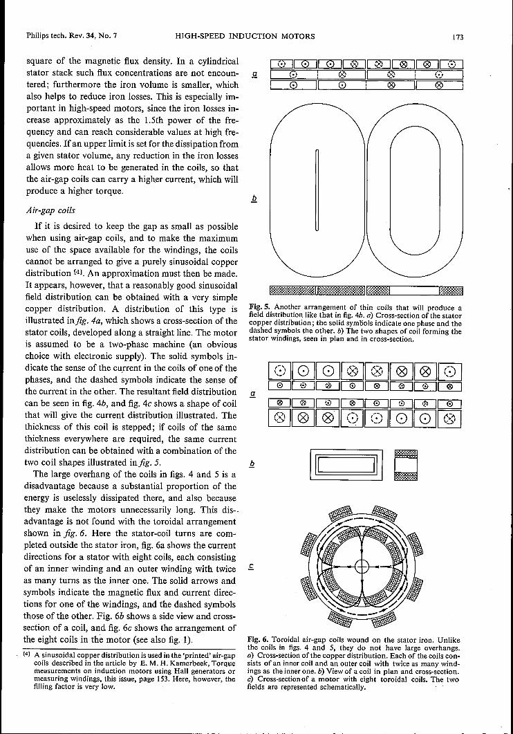
disadvantage because a substantial proportion of theenergy is uselessly dissipated there, and also becausethey make the motors unnecessarily long. This dis-.advantage is not found with the toroidal arrangementshown in fig. 6. Here the stator-coil turns are com-pleted outside the stator iron, fig. 6a shows the currentdirections for a stator with eight coils, each consistingof an inner winding and an outer winding with twiceas many turns as the inner one. The solid arrows andsymbols indicate the magnetic flux and current direc-tions for one of the windings, and the dashed symbolsthose of the other. Fig. 6b shows a side view and cross-section of a coil, and fig. 6e shows the arrangement ofthe eight coils in the motor (see also fig. I).[4] A sinusoidal copper distribution is used in the 'printed' air-gap
coils described in the article by E. M. H. Kamerbeek, Torquemeasurements on induction motors using Hall generators ormeasuring windings, this issue, page 153. Here, however, thefilling factor is very Iow.
Fig. 5. Another arrangement of thin coils that will produce afield distribution like that in fig. 4b. a) Cross-section of the statorcopper distribution; the solid symbols indicate one phase and thedashed symbols the other. b) The two shapes of coil forming thestator windings, seen in plan and in cross-section.
SJ.
[QJ[QJ[Q]~~~~[Q]~[I][I]~~~I ~) I~
ITJCIJI ~I IITJ~[B~~~~~[Q][Q][QJ[QJ~
Fig. 6. Toroidal air-gap coils wound on the stator iron. Unlikethe coils in figs. 4 and 5, they do not have large overhangs.a) Cross-section of the copper distribution. Each of the coils con-sists of an inner coil and an outer coil with twice as many wind-ings as the inner one. b) View of a coil in plan and cross-section.c) Cross-sectionof a motor with eight toroidal coils. The twofields are represented schematicaIly.

174 H.G.LAKERVELD Philips tech. Rev. 34, No. 7
The superiority ofthe field distribution obtained withair-gap coils, even with the simple copper distributiondiscussed here, can be seen from fig. 7. Fig. 7a showsthe result of a field-distribution measurement in a statorwith 12 slots, and fig. 7b shows the field distributionwhen air-gap coils like those in fig. 6 are used. Theapproximation to a sine curve here is a remarkablygood one.
Calculation of the torque
The torque of an electric motor can be calculated ifthe radial and tangential components of the magneticfield are known at every point of a surface situated inthe air gap and enclosing the rotor [5]. In our case thecalculation of these components requires the directsolution of Maxwell's equations for the air gap and forthe iron of the rotor and the stator. This is possible ifwe introduce a number of simplifying assumptions.The principal ones are that the stator iron has infinitelyhigh permeability so that the magnetic field-strength init is zero, and also has zero electrical conductivity.Another assumption is that the solution is independentof the coordinate along the motor shaft, which impliesthat there are no perturbing effects from the end facesof the rotor (we treat the problem as if these end faceswere infinitely far away, so that all the currents in therotor run parallel to the shaft). Furthermore the per-meability of the rotor iron is assumed to be constant,magnetic saturation does not therefore enter the argu-ment. In the next subsection the expressions thus foundwill be corrected for the end effects of the rotor and formagnetic saturation.
The magnetic fields calculated for this simplifiedmodel depend on the slip because the skin depth is dif-ferent at different speeds. These fields are used for cal-culating the torque; theexpression found iscomplicated,and will not be given here. A simplification is possible,however, if the values of the slip are not too small. Thisbecomes apparent when we derive the elements of theequivalent circuit of the motor from our knowledge ofthe magnetic field. This equivalent circuit [3] is shownin fig. 8; the form in fig. Sb can be derived from fig. Sa,and the accented quantities are known as referredquantities. We shall use them several times in the fol-lowing calculations. In our case the rotor resistance RI'and the leakage inductance of the rotor Lru, unlikethose of the squirrel-cage motor, are functions of themotor speed and hence ofthe slip s. Ifthe slip is greaterthan a minimum value Smin, it is found that both RI'and Le; are simply related to s. This can be seen infig. 9, where it is shown that RI' is proportional and Lruinversely proportional to Vs. The proportionality con-stant RrlVs will be referred to as rr and Rrf/Vs as r-'.
a
b
Fig.7. Results of measurements of the stator-field distribution(a) for a slotted stator, (b) for a stator with air-gap coils as infig. 6. The approxirnat io n to a sinusoid is far better in the secondcase. The measurement was made by exciting one stator phasewith d.c. and rotating a search coil with the rotor.
Q
Rs Lser L~er R;
b = fM' ~(t-I)R;
Fig. 8. Equivalent circuit for the induction motor. a) Non-referredform. R; and R,· are the resistances, Lsa and Lea the leakage in-ductances of stator and rotor. The values of RI' and Lru with thesolid rotor depend on the slip s. M is the mutual inductance be-tween stator and rotor. The resistance (lis - I)R!' represents themecha nical load; the total resistance in the rotor circuit is Ri}«.b) Referred form. The values assigned to the referred quantities(accented) are such that the sarne characteristics are measured atthe input terminals as in (a).

Philips tech. Rev. 34, No. 7 HIGH-SPEED INDUCTION MOTORS 175
The complicated expressions that we derive for Rr'and Lr,,' can then be simplified, as can also the expres-sion for the torque.To derive the rotor resistance Rr' and the various
inductances we use another model of the infinitely longrotor. We assume in this new model that the currentsflow in a thin sinusoidal copper layer applied to thesurface of the rotor; the rotor iron is assumed to benon-conducting and to have the same permeability asin the previous model. In this way we can obtain asimple definition for one value of the rotor resistance.This modification must not cause any change in therotor dissipation, the magnetic field in the air gap or thetotal magnetic field energy of the system. The currentsin the hypothetical copper layer can be derived fromthe calculated magnetic field. Since for a given torqueTe and an angular frequency w of the stator currentsthe total dissipation Pr in the rotor is known from therelation
P; = swTe,
we can now calculate the rotor resistance.The distributed inductance of this rotor model with
its copper layer is very low. The reason is that the si-nusoidal stator and rotor windings in this model areboth assumed to be in the air gap, so that the couplingis virtually ideal. To allow for the magnetic field energypresent in the real motor we must include a hypothet-
o VS;;;; -VsFig.9. The quantities Lr" and R, show a simple dependence onthe slip values S > Smin; in such cases Lr" ex; INs and R, ex; Vs.
J.l=OO0'=0S
Fig. 10. Model of a rotor R and a stator S used for calculating therotor end effects. The rotor has a length I and moves in thex-direction relative to the stator.
ical leakage inductance Lr" in the rotor circuit, com-pared with which the leakage inductance of the modelrotor is negligible. The Lr" plotted in fig. 9 is this hy-pothetical value. Calculation shows that Rr' = swLra'for s > Smln.
The forms which the referred values Rr' and Lru' take whenS> Smin are:
Rr' = nalis2 Vswp,f2a,Lra' = nalis2 Vp,/2swa.
Here a is the radius, I the length, p, the permeability and a theconductivity of the rotor; is is the peak value of the copper-distribution function for the stator.
The mutual inductance between stator and rotor (Min the equivalent circuit) can be calculated in the usualway from the dimensions and other characteristics ofthe model. At a given amplitude Îs of the a.c. currentsin the stator the torque is now given by:
Te = îs2Mj(Vsjsmax + VSmaxjs + V2) V2,
and the pull-out torque by:
Tmax = is2Mj(2 + V2) V2 = Îs2Mj4.83,
while
smax = 2rr'2j(wM)2
is the slip at which the motor develops the pull-outtorque.
Effect of finite rotor length
As mentioned earlier, the results found need to becorrected because in a real rotor the currents are notaxial everywhere but flow along closed paths, so thatparticularly near the end faces there are tangential andradial current components, which affect the operationof the motor [61.
To establish the magnitude of the correction thesecurrent components and the magnetic fields associatedwith them must be known. We are able to determinethese approximately on the basis of a model differentfrom those used previously. From the currents andfields we are then able to calculate the equivalentresistance and leakage inductance of the rotor as shownin the equivalent circuit in fig. 8. By comparing thesequantities with the corresponding ones for a rotor withno end effects we arrive at a correction factor.
The model used here is shown infig. 10. The statoris assumed to be infinitely long, whereas the rotor has
[5] See E. M. H. Kamerbeek, Torque measurements on inductionmotors using Hall generators or measuring windings, thisissue, page 153.
[6] H. Yee, Effects of finite length in solid-rotor induction ma-chines, Proc. lEE 118, 1025-1033, 1971.H. Yee and T. Wilson, Saturation and finite-length effects insolid-rotor induction machines, Proc. lEE 119, 877-882, 1972.
176 H. G. LAKERVELD Philips tech. Rev. 34, No. 7
a finite length I along the z-axis. The air gap is neglect-ed [7]. The rotor moves along the x-axis at a velocity vwith respect to the stator field. In this configuration asolution for Maxwell's equations can be found thatgives the magnitude and direction of the magnetic fluxdensity and the current density at every point of therotor.
z=Omm 20.14
40mm
the end faces than in the middle of the rotor, where thevalues found are about the same as those for an infini-tely long rotor. Consequently at the ends of the rotorthe product of By and the local tangential field-strengthHq, produced by the stator is greater than in the in-finitely long rotor, and this product ByHq, (the Max-well stress 15]) is a measure of the torque acting on the
3 4 5 la
0.02
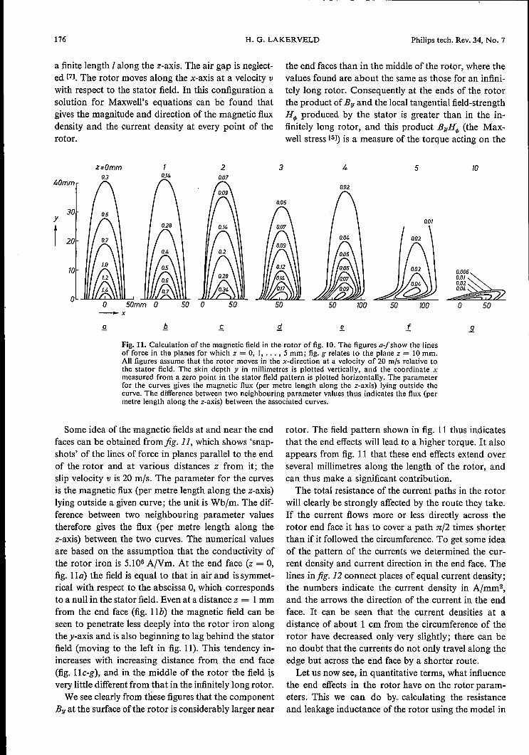
Fig. 11. Calculation of the magnetic field in the rotor of fig. 10. The figures a.Jshow the linesof force in the planes for which z = 0, I, ... , 5 mm; fig. g relates to the plane z = 10 mm.All figures assume that the rotor moves in the x-direction at a velocity of 20 mIs relative tothe stator field. The skin depth y in millimetres is plotted vertically, and the coordinate xmeasured from a zero point in the stator field pattern is plotted horizontally. The parameterfor the curves gives the magnetic flux (per metre length along the z-axis) lying outside thecurve. The difference between two neighbouring parameter values thus indicates the flux (permetre length along the z-axis) between the associated curves.
30y
t 20
la
-x
.£
Some idea of the magnetic fields at and near the endfaces can be obtained from fig. 11, which shows 'snap-shots' of the lines of force in planes parallel to the endof the rotor and at various distances z from it; theslip velocity v is 20 mis. The parameter for the curvesis the magnetic flux (per metre length along the z-axis)lying outside a given curve; the unit is Wb/m. The dif-ference between two neighbouring parameter valuestherefore gives the flux (per metre length along thez-axis) between the two curves. The numerical valuesare based on the assumption that the conductivity ofthe rotor iron is 5.106 A/Vm. At the end face (z = 0,fig. IIa) the field is equal to that in air and is symmet-rical with respect to the abscissa 0, which correspondsto a null in the stator field. Even at a distance z = 1mmfrom the end face (fig. lIb) the magnetic field can beseen to penetrate less deeply into the rotor iron alongthe y-axis and is also beginning to lag behind the statorfield (moving to the left in fig. 11). This tendency in-increases with increasing distance from the end face(fig. lIe-g), and in the middle of the rotor the field isvery little different from that in the infinitely long rotor.We see clearly from these figures that the component
By at the surface ofthe rotor is considerably larger near
0.01
s. 1
rotor. The field pattern shown in fig. 11 thus indicatesthat the end effects williead to a higher torque. It alsoappears from fig. 11 that these end effects extend overseveral millimetres along the length of the rotor, andcan thus make a significant contribution.The total resistance of the current paths in the rotor
will clearly be strongly affected by the route they take.If the current flows more or less directly across therotor end face it has to cover a path n/2 times shorterthan if it followed the circumference. To get some ideaof the pattern of the currents we determined the cur-rent density and current direction in the end face. Thelines in fig. 12 connect places of equal current density;the numbers indicate the current density in A/mm2,and the arrows the direction of the current in the endface. It can be seen that the current densities at adistance of about 1 cm from the circumference of therotor have decreased only very slightly; there can beno doubt that the currents do not only travel along theedge but across the end face by a shorter route.Let us now see, in quantitative terms, what influence
the end effects in the rotor have on the rotor param-eters. This we can do by, calculating the resistanceand leakage inductance of the rotor using the model in

Philips tech. Rev. 34, No. 7 HIGH-SPEED INDUCTION MOTORS 177
y
t
\ \ t f f I
-xFig. 12. Calculated currents in the end face of a rotor like the one in fig. 10. The curves connectthe points of equal current density; the numbers beside the curves give the current density inA/mm2. The arrows indicate the sense of the current component in the x,y-plane; the currentcomponent along the z-axis is not shown. It can be seen that the currents do not only flow atthe edge of the rotor but extend well over the end face.
1.0 d]! =5
'1t 0.6
0.4
0.2
0.8 5/12
2 5 10 20 30 40 50 60 70mls_V
-0.4
-0.6Fig. 13. The quantity 1) as a function of the slip velocity v for twovalues of the ratio of the diameter d to the length lof the rotor.Owing to the effects at the end faces ofthe rotor the values foundfor the the rotor resistance and leakage inductance have to bemultiplied by a correction factor (1 + 1)d/I). At greater slipvelocities 1) ~ 0.9.
-0.8
fig. 10. When we compare these with the values foundfor a piece of length I of an infinitely long rotor, wefind that both' quantities are greater by a factor of(1 + 'YJd/l) for a rotor of finite length I and diameter d.Here n is a function of the slip velocity and also of dil;the value of'YJ is given infig. 13 for two values of dll.We see that, except for very low slip velocities, 'YJ ispositive and is equal to about 0.9 at higher slip veloci-
ties. The pull-out slip Smax, which is proportional to thesquare of the rotor resistance, is greater by a factor of(1 + 'YJdjl)2 for a finite rotor length; this implies thatthe torque-speed characteristic near the synchronousspeed is less steep the shorter and thicker the rotor.
[7] The air gap is included in the calculations made by W. P. A.Joosen, Finite-length effect in a solid-rotor motor, Philips Res.Repts. 28, 485-495,,1973 (No. 5). .

178 H. G. LAKERVELD Philips tech. Rev. 34, No. 7
Magnetic saturation
It now only remains to correct our results for themagnetic saturation in the rotor iron, which until nowhas been assumed to be of uniform permeability. Whenwe determine the paths of the magnetic lines of forcein a cross-section of the rotor in our original model (inwhich the end effects were neglected) we obtain resultslike those shown in fig. 14. It can be seen from thisfigure that the lines of force become denser at the sur-face of the rotor, and that the density increases as theslip with respect to the stator field increases. This even-tually leads to magnetic saturation in the outer layerof the rotor.If the existing nonlinear relation between permeabil-
ity and field-strength is introduced into the equations,the calculations become impossibly complicated. Hereagain we have to make use of a simplified model. It is
o
Applying the corrections both for the end effects and for themagnetic saturation we find the following expressions for thereferred values of the rotor resistance and leakage inductance:
Rr,corr' = lSO alis2 Vswp,/2u (I + 1]d/l),Lra,corr' = i alis2 Vp,/2swu (1 + 1]d/l).
This yields a different value for the calculated torque:
Te = fs2M/(Vs/smax + VSmax/S + 1!V1.25) V1.25.
The pull-out torque is now greater:
Tmax = îs2 M/3.24,
a value which agrees very well with measurements.Unfortunately this is not the case with the pull-out slip,
Smax = 1.25 rr,corr'2/(wM)2,
which follows from the same assumption (rr,corr' is the
Wr
Fig. 14. Lines of force in a cross-section ofthe rotor for different frequencies ofthe a.c. currentin the rotor. The higher the frequency the more the lines of force concentrate at the surface ofthe rotor; the outer layer of the rotor finally becomes magnetically saturated, which affectsthe performance of the motor.
known that an exact calculation of magnetic fields andcurrent densities can be made for the case of an infinitehalf-space of ferromagnetic material characterized bya 'rectangular' B-H curve as shown infig. 15, at whosesurface there is a sinusoidally alternating tangentialmagnetic field [8l. This model shows some resemblancewith the solid rotor in which also, as can be seen infig. 14, the lines of force soon begin to bend over paral-lel to the surface.As in the case of the rotor, we can again define an
equivalent resistance and a leakage inductance for themodel. The impedances of both are identical in mod-ulus if we assume constant permeability, as we alsofound in the case of the solid rotor. If we use the B-Hcurve in fig. 15, however, we find that the equivalentresistance is twice as large as the modulus of the impe-dance of the leakage inductance. If we can now assumethat the occurrence of magnetic saturation in the solidrotor leads to the same change, then for the rotor withmagnetic saturation, we have Rr' = 2swLra'.[8] W. MacLean, Theory of strong electromagnetic waves in Fig. 15. The 'rectangular' B-H curve used for an approximate
massive iron, J. appI. Phys. 25, 1267-1270, 1954. calculation of the effects of magnetic saturation in the rotor.
corrected value of the proportionality constant r/mentioned earlier to allow for the end effects and themagnetic saturation). The reason for this is that rr,corr'is proportional to V#", and hence Smax to ft; now, how-ever, the permeability of the unsaturated rotor iron canno longer be taken into account, and instead an averagepermeability must be used for the whole rotor. At thesurface the rotor iron is saturated; the permeabilitythere (the saturation induction divided by the tangentialfield-strength at the surface) is therefore smaller thanin the bulk of the rotor. It appears empirically that a
B
to -H

Philips tech. Rev. 34, No. 7 HIGH-SPEED INDUCTION MOTORS 179
0.04NmF--==_=_== __
7;,
t0.03
0.02
4x704r/min
0.07
2 3_n
Fig. 16. Measured and calculated torque-speed characteristic ofa high-speed induction motor with a solid rotor; the dashedcurve is the calculated characteristic. The approximate descrip-tion of the end effects in the rotor and the magnetic saturation ofthe rotor iron is accurate enough-to bring the calculated charac-teristic close to the measured curve.
value of twice this surface permeability gives a satis-factory average value. When this is used in calculatingthe pull-out slip a theoretical torque-speed charac-teristic is obtained that agrees well with the results ofthe measurements (fig. 16).
Summary. Several prototype induction motors have been devel-oped for speeds of up to 40000 rev/min. Square-wave voltagesat frequencies up to 700 Hz are used for the supply. The iron los-ses have been reduced and the stator-field pattern improved bymaking the stator windings in the form ofthin coils in the air gaprather than putting them in slots. The motors have a 'solid iron'rotor without copper bars; the rotor currents give an increasingskin effect with increasing slip, which increases the starting torquein relation to the pull-out torque. The torque-speed characteristicis calculated with the aid of simplified models; it is necessary togo back to Maxwell's equations and to solve these for the models.This is done in steps; an infinitely long rotor of homogeneouspermeability is first assumed, and corrections are then made toallow for rotor end effects and for the magnetic saturation at thesurface.