Embed Size (px)
Citation preview

http://www.iaeme.com/IJMET/index.asp 635 [email protected]
International Journal of Mechanical Engineering and Technology (IJMET)
Volume 9, Issue 7, July 2018, pp. 635–646, Article ID: IJMET_09_07_066
Available online at http://www.iaeme.com/IJMET/issues.asp?JType=IJMET&VType=9&IType=7
ISSN Print: 0976-6340 and ISSN Online: 0976-6359
© IAEME Publication Scopus Indexed
DESIGN OF FLYWHEEL ROTOR AND MOTOR
FOR HIGH SPEED AUTOMOBILE
APPLICATIONS
Bharathi Thangaraj
Assistant Professor, Department of Electrical and Electronics Engineering,
Veltech Rangarajan & Dr.Sagunthala R&D Institute of Science and Technology, Avadi, India
S. Suchithra
Assistant Professor, Department of Electrical and Electronics Engineering,
Veltech Rangarajan & Dr.Sagunthala R&D Institute of Science and Technology, Avadi, India
P. Chandrasekar
Assosiate Professor, Department of Electrical and Electronics Engineering,
Veltech Rangarajan & Dr.Sagunthala R&D Institute of Science and Technology, Avadi, India
ABSTRACT
To provide continuous and constant power supply to the load side in the
automobile applications flywheel is proposing in this article, Flywheel not only stores
energy and also it can maintain stability of the system indirectly, this article deals
with design of different shapes of flywheel and electrical motor suitable for high speed
automobile applications, initially theoretical calculation, simulation of the flywheel
rotor is simulated using Powerful FEA packages, finally simulated flywheel, electrical
motor is tested with experimental setup.
Key words: Flywheel; Electric Motor; FEA packages; Experimental setup.
Cite this Article: Bharathi Thangaraj, S. Suchithra and P. Chandrasekar, Design of
Flywheel Rotor and Motor for High Speed Automobile Applications, International
Journal of Mechanical Engineering and Technology 9(7), 2018, pp. 635–646.
http://www.iaeme.com/IJMET/issues.asp?JType=IJMET&VType=9&IType=7
1. INTRODUCTION
Flywheel concept is ancient technique developed from potter wheels and spindle wheel,
Egyptians in the year 2400 BC rotating wheels used for handcraft pottery, after 1985 flywheel
concept is widely used in water pumps and also in power generation stations, flywheel can be
used for multiple things, some of the advantages of flywheel is storing mechanical energy in
the form of rotation, smoothening the output load side by providing constant and
uninterrupted output for certain period of time, electric automobiles commonly required
battery, electric motor, power electronic components ,generator and gearbox, in addition to

Bharathi Thangaraj, S. Suchithra and P. Chandrasekar
http://www.iaeme.com/IJMET/index.asp 636 [email protected]
this flywheel is placed inside the automobiles means stability , output continuity can also
increased. Figure 1, shows the block diagram of Flywheel placed in automobile.
Figure 1 Block diagram of Electric vehicle with flywheel
basically flywheel is depends on mechanical system, it is most commonly used along with
the motor or generator for maintaining smooth output ,evacuated containment is preferred for
high speed rotor spinning flywheel, windage losses is minimum once entire setup is placed
inside the evacuated containment [1], hybrid electric power can be fed from the battery, fuel
cell or super capacitors are most commonly used in low speed applications, hybridization like
diesel- electric vehicles can be useful for heavy duty as well as high speed vehicle
applications [2], for flywheel rotor highly reliable ,high starting torque motor is proffered for
good performance [3], motors like induction motor, permanent magnet synchronous motor,
brushless DC motor, brushed DC motor, Switched Reluctance motor, Synchronous reluctance
motor can also use for flywheel rotor, new flywheel energy storage system is proposed with
multiple motors coupled together to make efficient input to flywheel, this prototype is
proposed with typical three stages[4],
Figure 2 Flowchart for flywheel and motor analysis

Design of Flywheel Rotor and Motor for High Speed Automobile Applications
http://www.iaeme.com/IJMET/index.asp 637 [email protected]
During power generation station side also flywheel is preferred, in wind power generation
station also flywheel can be placed in another side, so that power from the wind generator as
well as flywheel power together coupled together for higher efficiency [5]. so in this article
mainly focused on optimized design of flywheel for high speed applications followed by
stress analysis of flywheel at last thermal analysis of flywheel is simulated using FEA
software's, simulated design is tested with experimental setups
2. DESIGN OF FLYWHEEL
FEA carried out based on some steps ,first preprocessing of the flywheel design, followed by
solution of the flywheel, finally post processing of the flywheel is carried out. Design of
different types of flywheel is drawn using FEA packages, Mesh and nodal analysis for
different types of flywheel is simulated, stress and thermal analysis of flywheel is important
for performance improvement in the electric vehicles, best simulated design of flywheel is
proposed for practical testing for electric vehicles. Design specifications of flywheel is shown
in table 1,based on this design specifications different types of flywheel is constructed using
FEA software packages.
Table 1 Design specifications of flywheel
Parameters Unit Value
Mass of the flywheel Kg 8
Outer diameter of flywheel mm 110
Inner diameter of flywheel mm 90
Speed of rotation of flywheel RPM 1400
Material of flywheel _ Steel
Thickness of the flywheel mm 20
For a flywheel angular velocity (ω) is the moment of inertia about its own axis of
symmetry.It is the measure of resistance to the torque applied on a spinning object.
For moment of inertia
(1)
Stored energy= sum of kinetic energy of individual mass elements that comprise the
flywheel
Kinetic energy in a rotating system is
(2)
=
(
) (3)
Speed fluctuations in flywheel
F= (4)
Coefficient of the speed fluctuation
(5)
Stress calculation:

Bharathi Thangaraj, S. Suchithra and P. Chandrasekar
http://www.iaeme.com/IJMET/index.asp 638 [email protected]
A physical quantity that expresses the internal forces that neighbouring particles of a
continuous material exert on each other. It is represented by sigma.
(6)
3. SIMULATION OF DIFFERENT TYPES OF FLYWHEELS
Based on the above formulas design of three different types of flywheel is proceeded,
dimensions are fixed ,inner and outer diameter of flywheel is drawn using FEA packages,
based on the air gap ducts space allocation is defined in the core of the flywheel rotor,
dimension is constant for all Rim, Disc and Spoke type flywheel, once wire frame model is
developed, material selection, mass of the flywheel and thickness of flywheel is applied for all
three types, figure 3.a, 3.b, 3.c. shown the solid model of flywheel, steel material is used for
core of the flywheel, thickness of in the post processing the simulation is run by giving fixed
values
`
Figure 3 (a) Solid model of Rim type flywheel Figure 3 (b) Solid model of Disc type flywheel
Figure 3 (c) Solid model of Spoke type flywheel
3.1. Stress Analysis
By using FEA software packages simulation for stress and thermal analysis is carried out for
Rim type, disc type and spoke type flywheel, once solid model is finished, stress analysis is
carried out, Fixing the speed of the flywheel rotation and mass of the flywheel is fixed,
dynamic stress analysis simulation is simulated by using Ansys software, from the stress
analysis simulation, stress occurred in the rim type flywheel is predominantly low compared

Design of Flywheel Rotor and Motor for High Speed Automobile Applications
http://www.iaeme.com/IJMET/index.asp 639 [email protected]
to other two types disc and spoke type flywheels. In Rim type flywheel more stress occurred
in the thin area supporting joints area of the rotor, less stress only occurred in the place of
outer core and shaft region indicated in the blue colour, red colour places indicated high value
of stress, in disc type flywheel stress occurrence is spread uniformly in the region of core
places of flywheel rotor, it indicates that lifespan and stress in more places is not healthy for
running flywheel for long time and also stress occurrence in the more leads to increase of
temperature, in spoke type flywheel because of excess of spokes presence near to the shaft
material withstand capability reduces and also stress occurred in the spokes leads to broken
level.
Figure 4 (a) Stress analysis of Rim type flywheel Figure 4 (b) Stress analysis of Disc type flywheel
Figure 4 (c) Stress analysis of Spoke type flywheel
3.2. Thermal Analysis
Thermal analysis of flywheel is important to analysis ,once thermal perfoemance of rotor is
poor meanas, agning factor of flywheel occurs, it heatup the core of the motor, performance
of rotor gets affected, heating of the rotor can be avoided by changing the matrial of the rotor ,
changing the physical appearance of the rotor,by changing the physical apperance also stress
ability should not goes to worst case,it has to satisfy all the limitation of stress and thermal
analysis of flywheel, In the Rim type structure thermal occured in the area of exterior core of
the flywheel, it can be cooled by external atmosphere air itself, so need for external cooling
device to cool down surface of flywheel,in disc type flywheel produces more heat near to the
center of the core areas, once time increases thermal level increases and satrted to spread all
over the area of rotor, core gets heated up means shaft everything gets heated up,it leads to
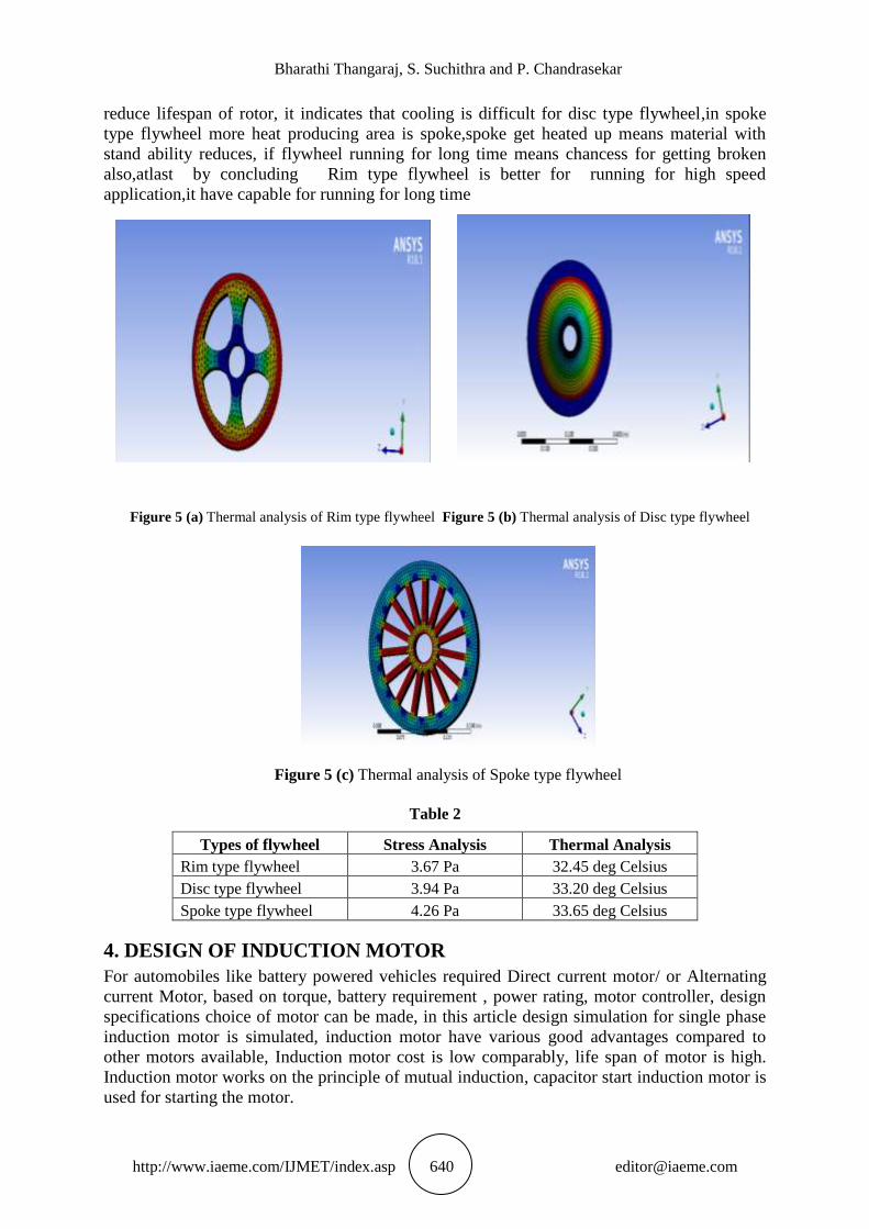
Bharathi Thangaraj, S. Suchithra and P. Chandrasekar
http://www.iaeme.com/IJMET/index.asp 640 [email protected]
reduce lifespan of rotor, it indicates that cooling is difficult for disc type flywheel,in spoke
type flywheel more heat producing area is spoke,spoke get heated up means material with
stand ability reduces, if flywheel running for long time means chancess for getting broken
also,atlast by concluding Rim type flywheel is better for running for high speed
application,it have capable for running for long time
Figure 5 (a) Thermal analysis of Rim type flywheel Figure 5 (b) Thermal analysis of Disc type flywheel
Figure 5 (c) Thermal analysis of Spoke type flywheel
Table 2
Types of flywheel Stress Analysis Thermal Analysis
Rim type flywheel 3.67 Pa 32.45 deg Celsius
Disc type flywheel 3.94 Pa 33.20 deg Celsius
Spoke type flywheel 4.26 Pa 33.65 deg Celsius
4. DESIGN OF INDUCTION MOTOR
For automobiles like battery powered vehicles required Direct current motor/ or Alternating
current Motor, based on torque, battery requirement , power rating, motor controller, design
specifications choice of motor can be made, in this article design simulation for single phase
induction motor is simulated, induction motor have various good advantages compared to
other motors available, Induction motor cost is low comparably, life span of motor is high.
Induction motor works on the principle of mutual induction, capacitor start induction motor is
used for starting the motor.

Design of Flywheel Rotor and Motor for High Speed Automobile Applications
http://www.iaeme.com/IJMET/index.asp 641 [email protected]
Table 3
Specification Value units
Inner diameter 26.03746 mm
Outer diameter 49 mm
Thickness 16.15753092 mm
Rated Speed 1400 Rpm
Shaft diameter 20 mm
No of stator slots 12 --
No of rotor poles 8 --
Material used for stator core Cold rolled steel --
Material used for rotor core Cold rolled steel --
Material used for coil Copper --
Number of turns 43 --
Type of coil Concentrated double
layer winding
--
4.1. FEA Analysis of Induction Motor
Single phase Induction motor of squirrel cage type rotor is designed for high speed electric
powered automobile applications, once Electric energy is given to the motor means motor
started to produce mechanical energy, this mechanical energy is given to the flywheel
,flywheel stores rotational energy and also it resist change in speed, at last flywheel is
connected to the wheels of the vehicle, some basic design details of flywheel is shown in table
3, twelve stator slots, eight rotor poles are used in this induction motor, solid model of single
phase induction motor is shown in figure 6, it shows that stator core and rotor core has cold
rolled steel material, rotor has made up of bars and end rings, end rings shorted by the copper
material ,once solid model of induction motor is designed, mesh analysis for designed
Induction motor is carried out, reduction of mesh size increases the output accuracy, mesh of
2mm dimension is used ,nodal values of 2547 is obtained in simulation, mesh analysis is
simulated only when there is no leakage in the design, if there is any leakage in the design
means mesh analysis is aborted during simulation, during preprocessing flux linkage ,current
distribution of Induction Motor is shown in figure 7 and figure 8, from that diagram it shows
clearly maximum flux density occurs in the motor is 0.855 Wb/m2
indicates in the red colour,
figure 8 shows maximum current density occurs in the stator slots of 5.05 A/m2. Input voltage
of 72 volts is given to the stator of Induction Motor, input voltage waveform is shown in
figure 9, Motor attain maximum speed of 1400 rpm. it slips with the percentage of 6.67 with
the synchronous speed. slip speed is shown in figure 10.torque value of the motor is shown in
the figure 11, maximum of 0.25 N-m value is obtained during simulation of Induction Motor.
Figure 6 Solid model of Induction Motor

Bharathi Thangaraj, S. Suchithra and P. Chandrasekar
http://www.iaeme.com/IJMET/index.asp 642 [email protected]
Figure 7 Flux linkage of Induction Motor
Figure 8 Current density of Induction Motor
Figure 9 Input Voltage waveform

Design of Flywheel Rotor and Motor for High Speed Automobile Applications
http://www.iaeme.com/IJMET/index.asp 643 [email protected]
Figure 10 Efficiency of Induction Motor
Figure 11 Torque value of Induction motor
From the table 4 designed IM simulation values are shown, from the figure 7 shows there
is no flux linkage in the machine, current density is also higher value, overall simulation of
IM is suitable to operate for automobile application
Table 4 Simulation results of IM
S.No FEA analysis of IM Values
1 Flux linkage 0.855 Wb/m2
2 Current density 5.05 A/m2
3 Maximum Torque 0.25 N-m
4 Slip percentage 6.667%
5 Efficiency 69%
4.2. Thermal Analysis of Induction Motor
Thermal analysis of Induction Motor is simulated using powerful FEA software, from this
thermal analysis thermal performance of machine at various conditions can be simulated,
Thermal

Bharathi Thangaraj, S. Suchithra and P. Chandrasekar
http://www.iaeme.com/IJMET/index.asp 644 [email protected]
Figure 12 Thermal graph of Induction Motor
analysis plays a vital role to improve the performance of machine, heat occurs in the
machine is low means efficiency of the machine also good, once heat producing in the coils or
core of the machine increases means efficiency of the machine also reduces, from the thermal
simulation indicates that more heat occurs the place of stator coils, initially room temperature
of the machine kept at 30 degree Celsius, simulation of the machine carried out up to 57
minutes, Thermal simulation of the machine is shown in figure 12, from the table 5 shows that
thermal value of the machine not exceeds 50 degree Celsius ,so designed Induction Motor is
suitable to operation
Table 5 Thermal results of Induction Motor
S.No Components of Induction
Motor
Maximum Temperature (Deg
Celsius)
1 Stator coil side 40.4
2 Stator tooth 39.5
3 Rotor tooth 37.9
4 Rotor bar 37.9
5 Shaft 36.5
5. HARDWARE DEVELOPMENT
Based on the simulation results of designed different types flywheel, effective flywheel is
chosen for prototype modeling, Rim type flywheel have good stress and thermal withstand
ability compared to other two types, similarly simulation results of IM is chosen because of its
good performance of torque power and speed values.
Prototype model of flywheel and IM is coupled by using belt conveyors with the V-Belt
ratio of 1:4 range, one end of IM is coupled with the Flywheel connected common shaft, so
from this setup one rotation of IM gives 4 rotation of flywheel, speed produced by the
flywheel 4 times higher than speed coming from the motor, figure 13, shows the setup
designed flywheel and IM ,this multiplied speed can be given to the transmission drive shaft
of the vehicle, but in prototype model another end also coupled with the IM to make the
flywheel rotate faster than normal speed to make more effective performance.

Design of Flywheel Rotor and Motor for High Speed Automobile Applications
http://www.iaeme.com/IJMET/index.asp 645 [email protected]
Figure 13 Prototype model of flywheel and Induction motor
Practical testing is tested for two minutes, from this testing machine with and without
flywheel is tested by turned off after reaching sixty seconds, machine without flywheel
reaches zero speed once it reaches 80 seconds, machine with flywheel can run maximum
speed of 1404 RPM, it takes extra 24 seconds to reach zero speed, machine with flywheel can
be suitable to operate at all conditions.
Figure 14 Time Vs speed curves with and without flywheel
6. CONCLUSIONS
This work focus on the design and analysis of flywheel and Induction motor for automobile
applications, usually instead of depending on gear system for multiplying speed of the vehicle
flywheel can be use, flywheel not only increase the speed, it can also helps to maintain
stability of the vehicle and also it stores mechanical energy in the form rotation energy, this
article deals with design of three different types of flywheel by following design algorithm
method for optimization and improve performance of the flywheel, some of the main
simulation testing like stress, thermal analysis is carried out for all three types of flywheel,
among three types, Rim type flywheel have better performance characteristics, simulation is
tested with powerful FEA software's. Electrical Motor plays a vital role for Electric Vehicles,
Compared to other Electric Motors ,Induction Motor have some good features, so design of
IM is designed using flowchart, designed IM is simulated using FEA software, once

Bharathi Thangaraj, S. Suchithra and P. Chandrasekar
http://www.iaeme.com/IJMET/index.asp 646 [email protected]
simulation results of IM and flywheel is good means taken for prototype developing,
Prototype model is tested in the experimental testing laboratory, prototype model is suitable to
operate for automobile applications, future scope of the research is carried out with BLDC
motor, different materials for flywheel, stress and thermal analysis for flywheel in prototype.
REFERENCES
[1] Paul P. Acarnley et al., "Design Principles For a Flywheel Energy Store for Road
Vehicles", in IEEE Transactions On Industry Applications, VOL. 32, NO. 6,
November/December 1996.
[2] Briat o. et al., "Principle, Design and Experimental Validation of a Flywheel-Battery
Hybrid Source For Heavy-Duty Electric Vehicles", IET Electr. Power Appl., Vol. 1, No.
5, September 2007.
[3] Ye Yuan et al., "Design and Analysis of Bearingless Flywheel Motor Specially For
Flywheel Energy Storage", Electronics Letters 8th January 2016 Vol. 52 No. 1 pp. 66–
68.
[4] Jian-guo Bu et al., "Optimization for Airgap Flux Density Waveform of Flywheel Motor
using NSGA-2 and Kriging Model Based on MaxPro Design", 2016 IEEE, pp. 1-7.
[5] Ehsan Ghaemi and Mojtaba Mirsalim ,"Design and prototyping of a new flywheel energy
storage system", IET Electric Power Applications, pp. 1-10.
[6] Dishang D. Trivedi, Urmil B. Bhatt and Santosh C. Vora, Application of EKF Based
Dynamic State Estimation For DFIG Rotor Power Control Under Faulty Current Sensor
Measurements. International Journal of Advanced Research in Engineering and
Technology, 8(4), 2017, pp 95–110
[7] Kuldeep R. Sanap, S.R. Paraskar and S.S. Jadhao . Broken Rotor Bar Fault Diagnosis of
Induction Motor by Signal Processing Techniques. International Journal of Electrical
Engineering & Technology , 8(1), 2017, pp 57-67