Embed Size (px)
Citation preview
JLMN-Journal of Laser Micro/Nanoengineering Vol. 9, No. 1, 2014
5
High-Speed Laser Printing of Silver Nanoparticles Ink
Ludovic RAPP*1, Emeric BIVER*1, Anne Patricia ALLONCLE*1 and Philippe DELAPORTE*1
*1 Aix-Marseille University, CNRS, LP3 - Lasers, Plasmas and Photonic Processes Laboratory, UMR 7341, 13288 Marseille cedex 9, France
We use the laser-induced forward transfer technique to print at high-speed long lines of metallic nanoparticle ink. A picosecond laser emitting at 343 nm with a repetition rate of 500 kHz is used to realize series of droplets and continuous lines by varying the distance between successive laser pulses. We find this latter parameter to be critical to obtain droplets of good quality, and use a time-resolved imaging technique to study its effects on the ink ejection. Single pass, two-pass and three-pass laser printing have been investigated. We have printed millimeter-long continuous silver lines of 20 µm width and thinner than 500 nm, at velocities up to 4 m/s. This work demonstrates the feasibility of using high repetition rate laser for the fast and reliable printing of conductive lines.
Keywords: Laser-induced forward transfer, LIFT, silver nanoparticles ink, time-resolved shadowgraphy, high speed, laser printing, laser direct-write.
Introduction
The field of microelectronics, especially organic and flexible electronics, is still looking for an efficient digital printing technique, which can deposit small amounts of material with micrometer precision at high speed. Laser-induced forward transfer (LIFT) is a very promising digital printing technique that is easily computer controlled and can successfully deposit a wide range of materials such as metals [1–5], polymers [6-10], nanoparticles inks [11-13] and pastes [14], and other complex materials [15]. It is very efficient to fabricate devices such as organic light emitting diodes [6,16,17], organic thin film transistors [18,19], sensors [20-23] and capacitors [24,25]. LIFT of liquids has also been intensively studied in the last decade to understand the ejection mechanisms [26-31] and to develop applications like bioprinting. In this study, we investigated the LIFT technique for the fabrication of fine conductive lines based on the printing of metallic nanoparticle ink for the implementation in microelectronics applications. A transparent substrate is coated with a thin layer of metallic nanoparticles ink. A laser pulse is then focused through it on the ink layer, and generates a cavitation bubble. Its expansion pushes the liquid away from the substrate and generates a high-speed jet, which forms a droplet on a receiver substrate placed nearby. Conductive lines have already been done using this technique [11,13] by printing overlapping droplets. In order to increase the speed of the process, we investigate the printing of several droplets at a high repetition rate with the goal of forming well-defined continuous lines.
Experimental details
The high frequency pulsed-laser used for the study was a frequency-tripled Yb:YAG fiber laser (Hegoa, EOLITE Systems) emitting at a wavelength of 343 nm with a pulse duration of 30 ps. Its repetition rate ranged from 0.2 to 2 MHz and an acousto-optic system allowed working in burst mode. For this study the repetition rate was set to 500 kHz.
A rotating wave plate and a polarizing beam-splitter cube controlled the beam energy. The laser beam was Gaussian and the focal spot size was ~20 µm. It irradiated the donor substrate from the top and the jet expanded downwards. The beam was moved in two directions by a scanner system (Scanlab Intelliscan 14) with galvanometric mirrors and focused by an F-theta telecentric objective. The positions of the donor and receiver substrates were independently controlled by motorized stages (X, Y and Z for the donor substrate, X and Y for the receiver). They were used for the initial positioning of the substrates which, then, stay immobile during the printing steps. A NANOLITE KL-M flash lamp (High-Speed Photo-System) delivering sparks of 16 ns is used to illuminate the jet expanding from the donor film during the shadowgraphy experiments. Two quartz lenses are used to image the region of interest, where the jet expands, on a fast QICAM 12-bits camera equipped with a 12X zoom lens system. The optical axis of this visualization setup was perpendicular to the laser beam and jet expansion axis. A digital delay generator (DG535, Stanford Research Systems) was used to tune the delay between the emission of the laser pulses and the triggering of the flash lamp. The shadowgraphy experiments were performed without receiver substrate.
The silver nanoparticles ink used for the study was purchased from SunChemical. It contained 20 % of silver nanoparticles (size: 80-100 nm), had a density of 1.22 g/mL and a viscosity of 10 to 13 mPa.s. The main solvents were ethanediol, ethanol, glycerine, 2-isopropoxyethanol. The ink was spin-coated for 30s at 2900 rpm (acceleration 1660 rpm/s) on quartz Suprasil® (transparent at the laser wavelength) donor substrates (2x2cm²). The average weight of the ink layer was 1.87 mg and its average thickness was 3.8 µm. Receiver substrates were silicon wafers. Samples with ink deposits were analyzed with a Leica DMC 3D confocal microscope. Then, to evaporate the solvents and bond the nanoparticles together , the printed lines were cured in an oven at 150°C for 30 min.
DOI: 10.2961/jlmn.2014.01.0002
JLMN-Journal of Laser Micro/Nanoengineering Vol. 9, No. 1, 2014
6
Results and discussion
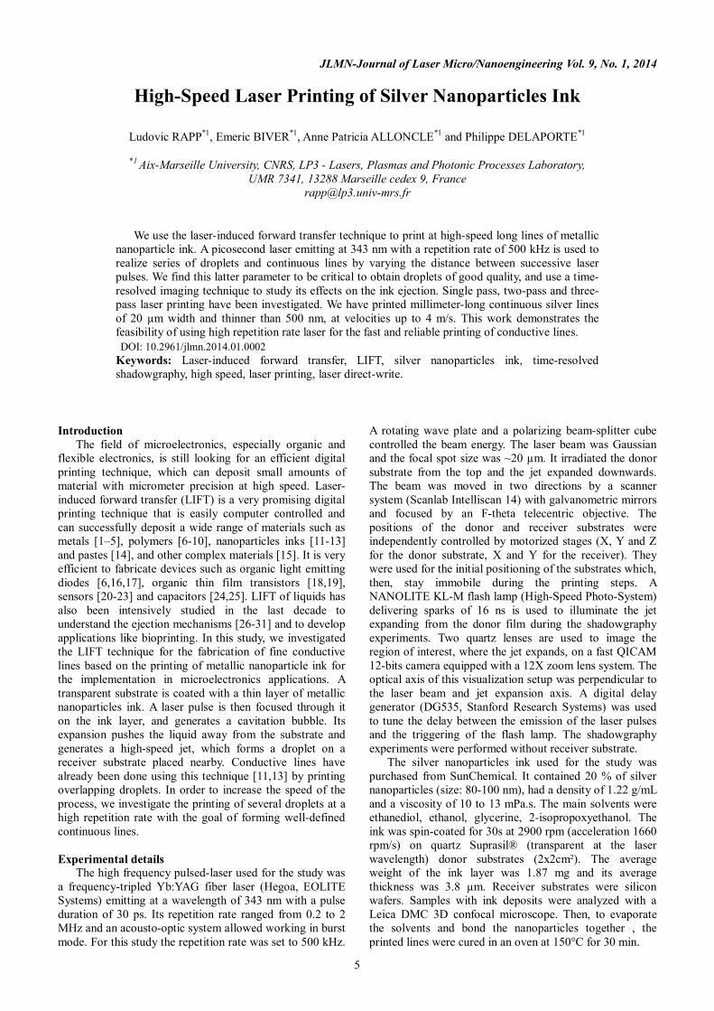
Laser printing of ink The laser printing of the silver nanoparticles ink
performed at pulse repetition rate of 500kHz has been investigated by varying the laser spots spacing with the goal of forming continuous lines. Figure 1 presents the printed structures for different spacing. The donor-receiver distance was 100 µm and the laser fluence was 30 mJ/cm2. The transfer was first studied for a laser spot spacing of 26 µm (figure 1a). A discussion on the choice of this distance can be found on [32]. Doted lines of well-resolved 16-µm diameter droplets were obtained. Their height before curing was ~1.9 µm and the volume of the droplets was ~260 µm3. All the droplets are similar, showing a reproducible process without any splashes or satellites. The spacing between the droplets was 9.93 µm +/- 0.35 µm and the percentage of single droplets on the lines is 100 %.
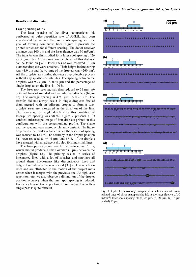
The laser spot spacing was then reduced to 21 µm. We obtained lines of rounded and well-defined droplets (figure 1b). The average spacing is 4.90 µm +/- 0.26 µm. The transfer did not always result in single droplets: few of them merged with an adjacent droplet to form a two-droplets structure, elongated in the direction of the line. The percentage of single droplets for this condition of laser-pulses spacing was 98 %. Figure 2 presents a 3D confocal microscope image of four droplets printed in this configuration with the corresponding profile. The shape and the spacing were reproducible and constant. The figure 1c presents the results obtained when the laser spot spacing was reduced to 18 µm. The accuracy in the droplet position has been reduced to +/- 4 µm, and 66 % of the droplets have merged with an adjacent droplet, forming small lines.
The laser pulse spacing was further reduced to 15 µm, which should produce a small overlap (1 µm) between the droplets (figure 1d). The printing results in series of interrupted lines with a lot of splashes and satellites all around them. Phenomena like discontinuous lines and bulges have already been observed [33] at low repetition rates and are attributed to the motion of the droplet mass center when it merges with the previous one. At high laser repetition rate, we also observe a diminution of the droplet position accuracy when the laser spot spacing is reduced. Under such conditions, printing a continuous line with a single pass is quite difficult.
Fig. 1 Optical microscopy images with schematics of laser-printed lines of silver nanoparticles ink at the laser fluence of 30 mJ/cm2; laser-spots spacing of: (a) 26 µm, (b) 21 µm, (c) 18 µm and (d) 15 µm.
JLMN-Journal of Laser Micro/Nanoengineering Vol. 9, No. 1, 2014
7
Fig. 2 3D confocal microscopy image of four printed droplets with the associated profile. The laser fluence was 30 mJ/cm2.
Time-resolved shadowgraphy experiments To investigate the loss of printing accuracy, we
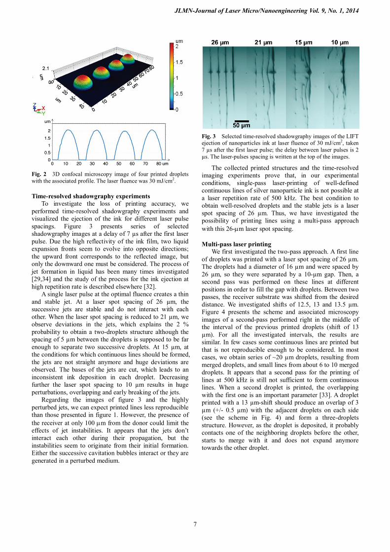
performed time-resolved shadowgraphy experiments and visualized the ejection of the ink for different laser pulse spacings. Figure 3 presents series of selected shadowgraphy images at a delay of 7 µs after the first laser pulse. Due the high reflectivity of the ink film, two liquid expansion fronts seem to evolve into opposite directions; the upward front corresponds to the reflected image, but only the downward one must be considered. The process of jet formation in liquid has been many times investigated [29,34] and the study of the process for the ink ejection at high repetition rate is described elsewhere [32].
A single laser pulse at the optimal fluence creates a thin and stable jet. At a laser spot spacing of 26 µm, the successive jets are stable and do not interact with each other. When the laser spot spacing is reduced to 21 µm, we observe deviations in the jets, which explains the 2 % probability to obtain a two-droplets structure although the spacing of 5 µm between the droplets is supposed to be far enough to separate two successive droplets. At 15 µm, at the conditions for which continuous lines should be formed, the jets are not straight anymore and huge deviations are observed. The bases of the jets are cut, which leads to an inconsistent ink deposition in each droplet. Decreasing further the laser spot spacing to 10 µm results in huge perturbations, overlapping and early breaking of the jets.
Regarding the images of figure 3 and the highly perturbed jets, we can expect printed lines less reproducible than those presented in figure 1. However, the presence of the receiver at only 100 µm from the donor could limit the effects of jet instabilities. It appears that the jets don’t interact each other during their propagation, but the instabilities seem to originate from their initial formation. Either the successive cavitation bubbles interact or they are generated in a perturbed medium.
Fig. 3 Selected time-resolved shadowgraphy images of the LIFT ejection of nanoparticles ink at laser fluence of 30 mJ/cm2, taken 7 µs after the first laser pulse; the delay between laser pulses is 2 µs. The laser-pulses spacing is written at the top of the images.
The collected printed structures and the time-resolved imaging experiments prove that, in our experimental conditions, single-pass laser-printing of well-defined continuous lines of silver nanoparticle ink is not possible at a laser repetition rate of 500 kHz. The best condition to obtain well-resolved droplets and the stable jets is a laser spot spacing of 26 µm. Thus, we have investigated the possibility of printing lines using a multi-pass approach with this 26-µm laser spot spacing.
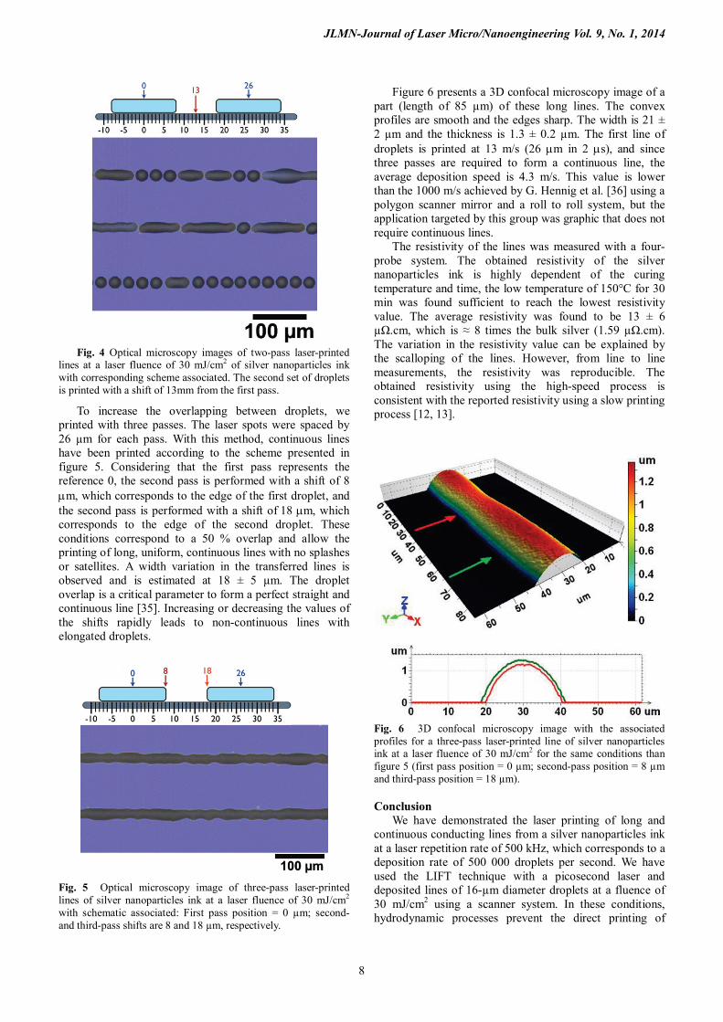
Multi-pass laser printing We first investigated the two-pass approach. A first line
of droplets was printed with a laser spot spacing of 26 µm. The droplets had a diameter of 16 µm and were spaced by 26 µm, so they were separated by a 10-µm gap. Then, a second pass was performed on these lines at different positions in order to fill the gap with droplets. Between two passes, the receiver substrate was shifted from the desired distance. We investigated shifts of 12.5, 13 and 13.5 µm. Figure 4 presents the scheme and associated microscopy images of a second-pass performed right in the middle of the interval of the previous printed droplets (shift of 13 µm). For all the investigated intervals, the results are similar. In few cases some continuous lines are printed but that is not reproducible enough to be considered. In most cases, we obtain series of ~20 µm droplets, resulting from merged droplets, and small lines from about 6 to 10 merged droplets. It appears that a second pass for the printing of lines at 500 kHz is still not sufficient to form continuous lines. When a second droplet is printed, the overlapping with the first one is an important parameter [33]. A droplet printed with a 13 µm-shift should produce an overlap of 3 µm (+/- 0.5 µm) with the adjacent droplets on each side (see the scheme in Fig. 4) and form a three-droplets structure. However, as the droplet is deposited, it probably contacts one of the neighboring droplets before the other, starts to merge with it and does not expand anymore towards the other droplet.
JLMN-Journal of Laser Micro/Nanoengineering Vol. 9, No. 1, 2014
8
Fig. 4 Optical microscopy images of two-pass laser-printed
lines at a laser fluence of 30 mJ/cm2 of silver nanoparticles ink with corresponding scheme associated. The second set of droplets is printed with a shift of 13mm from the first pass.
To increase the overlapping between droplets, we printed with three passes. The laser spots were spaced by 26 µm for each pass. With this method, continuous lines have been printed according to the scheme presented in figure 5. Considering that the first pass represents the reference 0, the second pass is performed with a shift of 8 µm, which corresponds to the edge of the first droplet, and the second pass is performed with a shift of 18 µm, which corresponds to the edge of the second droplet. These conditions correspond to a 50 % overlap and allow the printing of long, uniform, continuous lines with no splashes or satellites. A width variation in the transferred lines is observed and is estimated at 18 ± 5 µm. The droplet overlap is a critical parameter to form a perfect straight and continuous line [35]. Increasing or decreasing the values of the shifts rapidly leads to non-continuous lines with elongated droplets.
Fig. 5 Optical microscopy image of three-pass laser-printed lines of silver nanoparticles ink at a laser fluence of 30 mJ/cm2 with schematic associated: First pass position = 0 µm; second- and third-pass shifts are 8 and 18 µm, respectively.
Figure 6 presents a 3D confocal microscopy image of a
part (length of 85 µm) of these long lines. The convex profiles are smooth and the edges sharp. The width is 21 ± 2 µm and the thickness is 1.3 ± 0.2 µm. The first line of droplets is printed at 13 m/s (26 µm in 2 µs), and since three passes are required to form a continuous line, the average deposition speed is 4.3 m/s. This value is lower than the 1000 m/s achieved by G. Hennig et al. [36] using a polygon scanner mirror and a roll to roll system, but the application targeted by this group was graphic that does not require continuous lines.
The resistivity of the lines was measured with a four-probe system. The obtained resistivity of the silver nanoparticles ink is highly dependent of the curing temperature and time, the low temperature of 150°C for 30 min was found sufficient to reach the lowest resistivity value. The average resistivity was found to be 13 ± 6 µΩ.cm, which is ≈ 8 times the bulk silver (1.59 µΩ.cm). The variation in the resistivity value can be explained by the scalloping of the lines. However, from line to line measurements, the resistivity was reproducible. The obtained resistivity using the high-speed process is consistent with the reported resistivity using a slow printing process [12, 13].
Fig. 6 3D confocal microscopy image with the associated profiles for a three-pass laser-printed line of silver nanoparticles ink at a laser fluence of 30 mJ/cm2 for the same conditions than figure 5 (first pass position = 0 µm; second-pass position = 8 µm and third-pass position = 18 µm). Conclusion
We have demonstrated the laser printing of long and continuous conducting lines from a silver nanoparticles ink at a laser repetition rate of 500 kHz, which corresponds to a deposition rate of 500 000 droplets per second. We have used the LIFT technique with a picosecond laser and deposited lines of 16-µm diameter droplets at a fluence of 30 mJ/cm2 using a scanner system. In these conditions, hydrodynamic processes prevent the direct printing of
JLMN-Journal of Laser Micro/Nanoengineering Vol. 9, No. 1, 2014
9
continuous lines in a single step. Time-resolved shadowgraphy experiments of the ink ejection have showed that the small laser spot spacing required to get a sufficient overlapping to form continuous lines, leads to instable jets degrading the deposition precision and quality. Two-pass printing has not been sufficient to form continuous lines and resulted in series of merged droplets. The best condition is a three-pass laser printing with an overlap of 50 % between the droplets. Well-defined continuous silver lines, 20 µm-wide and ∼500 nm-thick, after curing, have been printed over few millimeters at an average speed of 4.3 m/s. This work demonstrates the possibility of using high repetition rate lasers for the printing of thin conductive lines with high resolution and high velocity. Acknowledgments This work has been done in the frame of the CIMPACA project and has been supported by the French General (CG13) and Regional (CRPACA) Councils, FEDER, Institut Carnot STAR and ARCSIS.
References [1] C. Germain, L. Charron, L. Lilge, Y. Tsui, Appl. Surf.
Sci. 253 (2007) 8328. [2] L. Yang, C. Wang, X. Ni, Z. Wang, W. Jia, L. Chai,
Appl. Phys. Lett. 89 (2006) 161110. [3] I. Zergioti, S. Mailis, N.A. Vainos, P.
Papakonstantinou, C. Kalpouzos, C.P. Grigoropoulos, C. Fotakis, Glass 582 (2000) 579.
[4] A.I. Kuznetsov, R. Kiyan, B.N. Chichkov, Opt. Express 18 (2010) 21198.
[5] D.P.Banks, C.Grivas, J.D.Mills, R.W.Eason, I.Zergioti. Appl. Phys. Lett. 89 (2006) 193107.
[6] G.B. Blanchet, Y.-L. Loo, J. a. Rogers, F. Gao, C.R. Fincher, Appl. Phys. Lett. 82 (2003) 463.
[7] R. Fardel, M. Nagel, F. Nüesch, T. Lippert, A. Wokaun, Appl. Phys. Lett. 91 (2007) 061103.
[8] L. Rapp, C. Cibert, A.P. Alloncle, P. Delaporte, Appl. Surf. Sci. 255 (2009) 5439.
[9] B. Thomas, A.P. Alloncle, P. Delaporte, M. Sentis, S. Sanaur, M. Barret, P. Collot, Appl. Surf. Sci. 254 (2007) 1206.
[10] V. Dinca, R. Fardel, J. Shaw-Steward, F. Di Pietrantonio, D. Cannata, M. Benetti, E. Verona, A. Palla-Papavlu, M. Dinescu, T. Lippert, Sensor letter 8 (3) (2010) 436.
[11] M. Duocastella, H. Kim, P. Serra, A. Piqué, Appl. Phys. 106 (2012) 471.
[12] L. Rapp, J. Ailuno, A.P. Alloncle, P. Delaporte, Opt. Express 19 (2011) 21563.
[13] H. Kim, R.C.Y. Auyeung, S.H. Lee, A.L. Huston, A. Piqué, A. Piqué. Appl Phys A 96 (2009) 441–445
[14] A. Piqué, J. Laser Micronanoengineering 3 (2008) 163.
[15] C.B. Arnold, P. Serra, A. Piqué, MRS Bull. 32 (2007) 23.
[16] N.T. Kattamis, N.D. McDaniel, S. Bernhard, C.B. Arnold, Org. Electron. 12 (2011) 1152.
[17] J.R.H. Shaw-Stewart, T. Mattle, T.K. Lippert, M. Nagel, F. a. Nüesch, a. Wokaun, J. Appl. Phys. 113 (2013) 043104.
[18] L. Rapp, S. Nénon, A.P. Alloncle, C. Videlot-Ackermann, F. Fages, P. Delaporte, Appl. Surf. Sci. 257 (2011) 5152.
[19] L. Rapp, A.K. Diallo, A.P. Alloncle, C. Videlot-Ackermann, F. Fages, P. Delaporte, Appl. Phys. Lett. 95 (2009) 171109.
[20] V. Tsouti, C. Boutopoulos, D. Goustouridis, I. Zergioti, P. Normand, D. Tsoukalas, S. Chatzandroulis, Sensors Actuators B Chem. 150 (2010) 148.
[21] E. Touloupakis, C. Boutopoulos, K. Buonasera, I. Zergioti, M. Giardi, Anal. Bioanal. Chem. 402 (2012) 3237.
[22] A. Piqué, D.B. Chrisey, J.M. Fitz-Gerald, R.A. McGill, R.D.Y. Auyeung, H.D. Wu, S. Lakeou, V. Nguyen, R. Chung, M. Duignan, J. Mater. Res. 15 (2000) 1872.
[23] D. Cannata, M. Benetti, F. Di Pietrantonio, E. Verona, A. Palla-Papavlu, V. Dinca, M. Dinescu, T. Lippert. Sensors and Actuators B 173 (2012) 32
[24] C.B. Arnold, R.C. Wartena, B. Pratap, K.E. Swider-lyons, A. Pique, Spie Lase 2002, 2002, pp. 353–360.
[25] D. Chrisey, A. Pique, J. Fitz-Gerald, R.C. Auyeung, R. McGill, H. Wu, M. Duignan, Appl. Surf. Sci. 154-155 (2000) 593.
[26] M. Duocastella, J.M. Fernández-Pradas, J. Domínguez, P. Serra, J.L. Morenza, Appl. Phys. 93 (2008) 941.
[27] I. Zergioti, a. Karaiskou, D.G. Papazoglou, C. Fotakis, M. Kapsetaki, D. Kafetzopoulos, Appl. Phys. Lett. 86 (2005) 163902.
[28] M. Duocastella, J.M. Fernández-Pradas, P. Serra, J.L. Morenza, Appl. Phys. 93 (2008) 453.
[29] M. Duocastella, J.M. Fernández-Pradas, J.L. Morenza, P. Serra, J. Appl. Phys. 106 (2009) 084907.
[30] M. Duocastella, a. Patrascioiu, V. Dinca, J.M. Fernández-Pradas, J.L. Morenza, P. Serra, Appl. Surf. Sci. 257 (2011) 5255.
[31] M.S. Brown, N.T. Kattamis, C.B. Arnold, Microfluid. Nanofluidics 11 (2011) 199.
[32] E. Biver, L. Rapp, A-P. Alloncle, Ph. Delaporte, Appl. Surf. Sci. (2013) in press, available online http://dx.doi.org/10.1016/j.apsusc.2013.10.042
[33] A. Palla-Papavlu, C. Córdoba, A. Patrascioiu, J.M. Fernández-Pradas, J.L. Morenza, P. Serra, Appl. Phys. A 110 (4) (2013) 751.
[34] A. Pearson, E. Cox, J. R. Blake, S. R. Otto, Engineering Analysis with Boundary Elements 28 (2004) 295.
[35] A. Palla-Papavlu, C. Córdoba, A. Patrascioiu, J.M. Fernández-Pradas, J.L. Morenza, P. Serra, App. Phys. A 110 (2013) 751–755.
[36] G. Hennig, T. Baldermann, C. Nussbaum, M. Rossier, A. Brockelt, L. Schuler, G. Hochestein, J. of Laser and Micro/Nanoengineering 7 (3) (2012) 299.
(Received: July 22, 2013, Accepted: December 14, 2013)