Embed Size (px)
Citation preview

High Speed • High Accuracy Eddy Current Type Digital Displacement Sensor
GP-X SERIES
High-speed sampling and high resolution. The new choice for even more variegated data collection and processing.
25!s & 0.02%F.S.
Conforming toEMC Directive
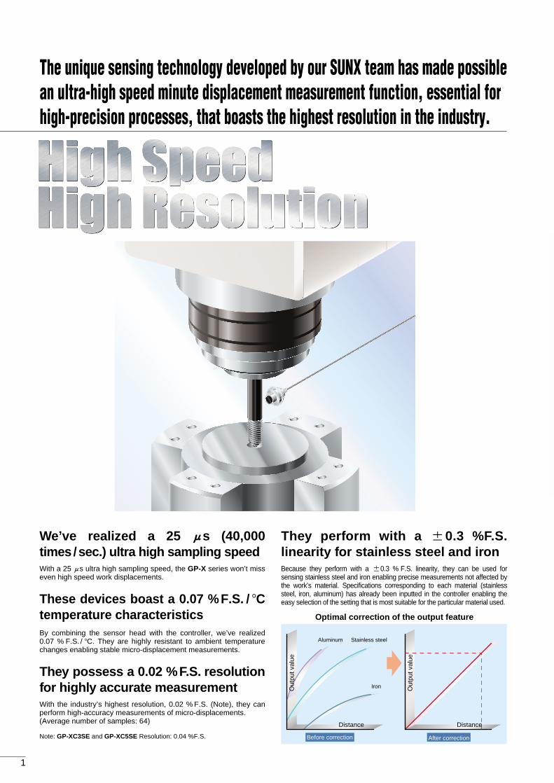
The unique sensing technology developed by our SUNX team has made possible an ultra-high speed minute displacement measurement function, essential for high-precision processes, that boasts the highest resolution in the industry.
1
We’ve realized a 25 ¨s (40,000 times / sec.) ultra high sampling speedWith a 25 !s ultra high sampling speed, the GP-X series won’t miss even high speed work displacements.
These devices boast a 0.07 % F.S. / C temperature characteristicsBy combining the sensor head with the controller, we’ve realized 0.07 % F.S. / C. They are highly resistant to ambient temperature changes enabling stable micro-displacement measurements.
They possess a 0.02 % F.S. resolution for highly accurate measurementWith the industry’s highest resolution, 0.02 % F.S. (Note), they can perform high-accuracy measurements of micro-displacements.(Average number of samples: 64)
Note: GP-XC3SE and GP-XC5SE Resolution: 0.04 %F.S.
They perform with a 0.3 %F.S. linearity for stainless steel and ironBecause they perform with a 0.3 % F.S. linearity, they can be used for sensing stainless steel and iron enabling precise measurements not affected by the work’s material. Specifications corresponding to each material (stainless steel, iron, aluminum) has already been inputted in the controller enabling the easy selection of the setting that is most suitable for the particular material used.
Optimal correction of the output feature
Aluminum Stainless steel
Iron Out
put v
alue
Out
put v
alue
DistanceDistance
Before correction After correction
2
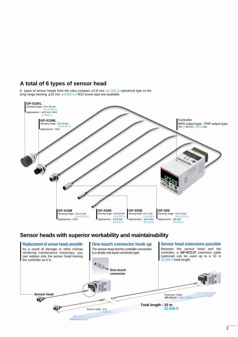
Sensor head extensions possibleBetween the sensor head and the controller, a GP-XCCJ7 extension cable (optional) can be used up to a 10 m 32.808 ft total length.
One-touch connector hook upThe sensor head and the controller connection is a simple one-touch connector type.
Replacement of sensor heads possibleAs a result of damage or other mishap rendering maintenance necessary, you can replace only the sensor head leaving the controller as it is.
Sensor heads with superior workability and maintainability
A total of 6 types of sensor head6 types of sensor heads from the ultra compact "3.8 mm "0.150 in cylindrical type to the long range sensing "22 mm "0.866 in / M12 screw type are available.
One-touch connector
Sensor head Extension Cable GP-XCCJ7 : 7 m 22.966 ft
Sensor cable : 3 m 9.843 ft
Total length : 10 m 32.808 ft
GP-X22KLSensing range : 0 to 10 mm
0 to 0.394 inAppearance : "22 mm / M12
"0.866 in
GP-X12MLSensing range : 0 to 5 mm
0 to 0.197 inAppearance : M12
GP-X10MSensing range : 0 to 2 mm
0 to 0.079 inAppearance : M10
ControllerNPN output type , PNP output typeDIN 48 mm 1.890 in size
GP-X3SESensing range : 0 to 0.8 mm
0 to 0.031 inAppearance : "3.8 mm
"0.150 in
GP-X5SESensing range : 0 to 1 mm
0 to 0.039 inAppearance : "5.4 mm
"0.213 in
GP-X8SSensing range : 0 to 2 mm
0 to 0.079 inAppearance : "8 mm
"0.315 in

The SUNX sensor design policy has realized controllers that are easy to use on-site.
3
The 5-digit, dual, 2-color digital display offers great visibilityIf the measurement results fall within the setting range (GO), they will appear on the lower digital display in green. If they are out of range (HI, LO), they will be displayed in the upper digital in orange. The display position and color change allows for accurate visibility even for momentary changes.
Digital input display enabling easy settingIts dual digital display enables numerical setting while verifying setting items for each mode. Even when sensing, it enables the verification of the main settings.
Panel mounting type Controller Compact type DIN 48 mm 1.890 in size
Out of setting range (upper threshold)
Sensing values within setting range
Out of setting range (lower threshold)
Sensing values
Average number ofsamples setting value
Simple setting modeManual mode
Upper threshold value
Lower threshold value
Setting value verifiable even in sensing mode
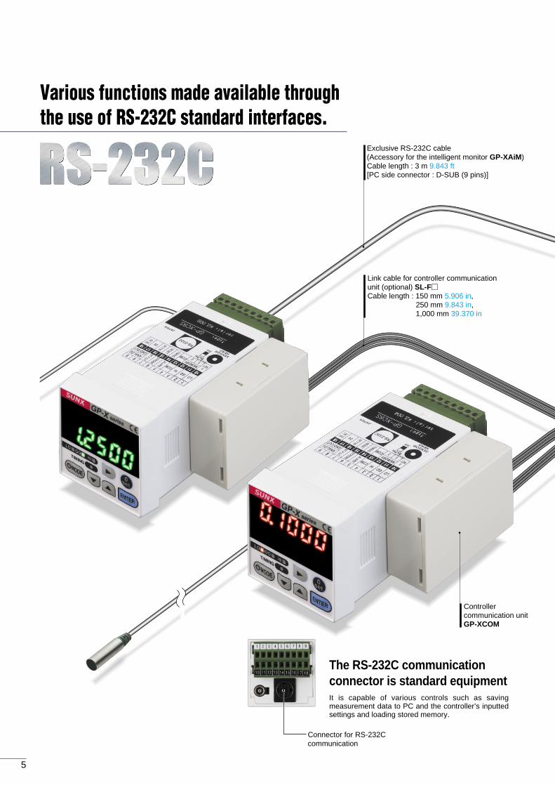
Various functions made available through the use of RS-232C standard interfaces.
5
Controller communication unitGP-XCOM
Exclusive RS-232C cable(Accessory for the intelligent monitor GP-XAiM)Cable length : 3 m 9.843 ft[PC side connector : D-SUB (9 pins)]
Link cable for controller communication unit (optional) SL-FCable length : 150 mm 5.906 in,
250 mm 9.843 in, 1,000 mm 39.370 in
The RS-232C communication connector is standard equipmentIt is capable of various controls such as saving measurement data to PC and the controller’s inputted settings and loading stored memory.
Connector for RS-232C communication

6
Intelligent monitor (GP-XAiM) optimal for collecting and analyzing measurement data. (Exclusive RC-232C cable is attached)
An intelligent monitor capable of the settings for each measurement conditions and waveform display monitoring. It can perform waveform monitoring, which could until now only be done by the oscilloscope, as well as the simple loading and saving onto a PC of settings for each condition and function.
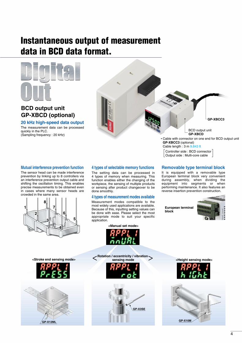
Enables sensors data comparisons and calculations3-value judgment output for calculating measurement data conformity and calculation results between 2 interconnected controllers is rendered possible. The calculation function equipment renders digital panel controllers unnecessary.
Datalink between sensors possibleThe controller communication unit GP-XCOM (optional) can be linked to up to 8 controllers and load via just one RS-232C cable each controller settings and measurement data to a PC.
Sensor A and sensor B can be linked together and measurement can be calculated (a – b) to detect difference in object.
Maximum of eight controllers
Controller communication unit Link cableData sent to a PC via the RS-232C
ba
Sensor B Sensor A
(a – b)
object (a – b) : difference in object

BCD output unit Cable with connector on one end for BCD output unit
GP-X
7
Cable with connector on one end for BCD output unit
Controller communication unit
Link cable for controller communication unit
Intelligent monitor
Extension cable for sensor head
GP-XBCDBCD output unitThis unit outputs measurement values in BCD data format at a high speed.• Sampling frequency : 20 kHz
Up to 8 controllers can be linked.
Cable for BCD data output unit.• 26-core cable with connector on one end
GP-XCOM
Length: 7 m 22.966 ft
SL-F150
GP-XBCC3
SL-F1000
SL-F250
GP-XAiM
GP-XCCJ7
Length: 1,000 mm 39.370 in
Length: 250 mm 9.843 in
Length: 150 mm 5.906 in
This cable links the controller communication units. Select as per the cable length.
This cable with connector is for extensions between the sensor head and controller.
Monitoring settings for each measurement condition and measurement waveforms is enabled by way of a PC.• One exclusive RS-232C cable (3 m 9.843 ft length) is attached.
BCD output unitGP-XBCD
ORDER GUIDE
OPTIONS
Designation DescriptionModel No.
Cable with connector on one end for BCD output unit GP-XBCC3
Controller communication unitLink cable for controller communication unit
Link cable for controller communication unit SL-F
Controller communication unitGP-XCOM
• GP-XAiMIntelligent monitor
• GP-XCCJ7
Extension cable for sensor head
M12
351.378
"220.866
Note: High resolution types (GP-XC3S, GP-XC5S: 0.02 % F.S., average number of samples: 64) are available. These products correspond to the Export Trade Administration Act of Japan. Shipping them outside Japan requires special permission from the Japanese government regarding stipulations in Foreign Exchange and Foreign Trade Law. Please contact our office for details.
Sensor heads ControllerSensing range
Set Model No.(Sensor head model No.)Type
Appearance (mm in)Comparative output
0 to 0.8 mm0 to 0.031 in
0 to 1 mm0 to 0.039 in
0 to 2 mm0 to 0.079 in
0 to 2 mm0 to 0.079 in
0 to 5 mm0 to 0.197 in
0 to 10 mm0 to 0.394 in
"3.8"0.150
170.669
"5.4"0.213
170.669
"8"0.315 17
0.669
170.669
M10
210.827
M12
GP-XC3SE(GP-X3SE) (Note)
GP-XC3SE-P(GP-X3SE) (Note)
GP-XC5SE(GP-X5SE) (Note)
GP-XC5SE-P(GP-X5SE) (Note)
GP-XC8S(GP-X8S)
GP-XC8S-P(GP-X8S)
GP-XC10M(GP-X10M)
GP-XC10M-P(GP-X10M)
GP-XC12ML(GP-X12ML)
GP-XC12ML-P(GP-X12ML)
GP-XC22KL(GP-X22KL)
GP-XC22KL-P(GP-X22KL)
NPN open-collector transistor
PNP open-collector transistor
NPN open-collector transistor
PNP open-collector transistor
NPN open-collector transistor
PNP open-collector transistor
NPN open-collector transistor
PNP open-collector transistor
NPN open-collector transistor
PNP open-collector transistor
NPN open-collector transistor
PNP open-collector transistor
Non
-thr
eade
d ty
pe s
enso
r he
adT
hrea
ded
type
sen
sor
head
Length: 3 m 9.843 ft
833.268
481.890
481.890
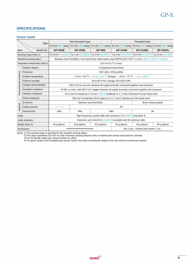
SPECIFICATIONS
Sensor heads
GP-X
8
Item Model No.
Non-threaded type
For 0.8 mm 0.031 in sensing
Threaded type
GP-X3SE
0 to 0.8 mm 0 to 0.031 in
For 1 mm 0.039 in sensing
GP-X5SE
0 to 1 mm 0 to 0.039 in
For 2 mm 0.079 in sensing
GP-X8S
0 to 2 mm 0 to 0.079 in
For 2 mm 0.079 in sensing
GP-X10M
0 to 2 mm 0 to 0.079 in
For 5 mm 0.197 in sensing
GP-X12ML
0 to 5 mm 0 to 0.197 in
For 10 mm 0.394 in sensing
GP-X22KL
0 to 10 mm 0 to 0.394 in
Protection
Pollution degree
Ambient temperature
Ambient humidity
Voltage withstandability
Insulation resistance
Shock resistance
Vibration resistance
Enclosure
Cable protector
Sensing Part
Weight (Note 4)
Accessories
Cable extension
Cable
Env
ironm
enta
l res
ista
nce
Mat
eria
l
Stainless steel (SUS304) / Iron sheet [Cold rolled carbon steel (SPCC)] 6060t 1 mm 2.3622.362t 0.039 in
0.07 % F.S./C or less
3 (Industrial environment)
IP67 (IEC), IP67g (JEM)
10 to55 C 14 to131 F, Storage: 20 to70 C 4 to158 F
35 to 85 % RH, Storage: 35 to 85 % RH
250 V AC for one min. between all supply terminals connected together and enclosure
20 MΩ, or more, with 250 V DC megger between all supply terminals connected together and enclosure
10 to 150 Hz frequency, 0.75 mm 0.030 in amplitude in X, Y and Z directions for two hours each
500 m/s2 acceleration (50 G approx.) in X, Y and Z directions for five times each
High frequency coaxial cable with connector, 3 m 9.843 ft long (Note 3)
Extension up to total 10 m 32.808 ft is possible with the optional cable
Temperature characteristics (Note 2)
Standard sensing object
Sensing range (Note 1)
40 g approx. 40 g approx. 40 g approx.
Stainless steel (SUS303)
50 g approx.
PP
45 g approx.
Nut: 2 pcs., Toothed lock washer: 1 pc.
80 g approx.
ABS PAR ABS PA
Brass (Nickel plated)
Notes: 1) The sensing range is specified for the standard sensing object. 2) This value represents 20 to 60 % of the maximum sensing distance when combining the sensor head and the controller. 3) For the flexible cable type, please contact our office. 4) The given weight of the threaded type sensor head is the value including the weight of the nuts and the toothed lock washer.
Type

GP-X
9
Current consumption
Accessory
Material
Weight
Hold input
Output 5 digits BCD, Polarity indication, VALID
Model No.
SPECIFICATIONS
Controllers
BCD output unit
GP-XBCDModel No.
Enclosure: ABS
30 g approx.
Mounting bracket [Stainless steel (SUS304)]: 1 pc.
20 mA or less
N-channel MOSFET open drain• Maximum sink current: 50 mA• Applied voltage: 30 V DC or less (between output and GND)• Residual voltage: 1 V or less (at 50 mA sink current)
Non-voltage contact or NPN open-collector transistor input• Low: 0 to 1 V • High: Open
Note: Connects to the control device with GP-XBCC3 cable with connector on one end for BCD output unit (3 m 9.843 ft cable length, optional).
GP-XCOM
Controller communication unit
Current consumption
Material
Weight
Accessory
5 mA or less
Enclosure: ABS
20 g approx.
Mounting bracket [Stainless steel (SUS304)]: 1 pc.
Note: Each GP-XCOM is connected using a link cable for controller com-munication units (SL-F, optional).When GP-XCOM is used, controllers cannot communicate if their software versions are not compatible (Ver. 1.06 or earlier version with Ver 2.00 or later version).Check the software version and use the correct combination.
Item
Type
Set model No.
Supply voltage
Current consumption
Resolution (Note 1)
Sampling frequency
Linearity (Note 1)
Temperature characteristics (Note 2)
Analog voltage output
Response time
Utilization category
Output number
Output operation
Short-circuit protection
External input
Serial I/O
Zero-set setting method
MODE
HI
GO
LO
TIMING
Upper line digital display part
Lower line digital display part
Pollution degree
Ambient temperature
Ambient humidity
EMC
Vibration resistance
Shock resistance
Material
Weight
Accessory
Indi
cato
rsEn
viro
nmen
tal r
esis
tanc
e
GP-XC-P
NPN output PNP output
GP-XC
24 V DC 10 % Ripple P-P 10 % or less
150 mA or less
40 kHz (25 !s)
Within 0.3 % F.S.
0.07 % F.S./C or less
Output voltage: 5 to 5 V (Note 3), Output impedance: 100 Ω approx.
75 !s (maximum speed)
DC-12 or DC-13
HI / GO / LO 3 value output
Incorporated
RS-232C
Push button setting / External input setting
Orange LED (lights up when in mode status)
Orange LED (lights up when the upper limit value is exceeded)
Green LED (lights up when within the upper and lower limit values)
Orange LED (lights up when less than the lower limit value)
Green LED (lights up as per the external or internal trigger timing)
5 digit orange LED (display of numerical values out of upper and lower limit values)
5 digit green LED (display of numerical values within the upper and lower limit values)
3 (Industrial environment)
0 to50 C 32 to 122 F (No dew condensation), Storage: 0 to50 C 32 to 122 F
35 to 85 % RH, Storage: 35 to 85 % RH
EN 61000-6-2, EN 61000-6-4
10 to 55 Hz frequency, 0.75 mm 0.030 in amplitude in X, Y and Z directions for two hours each
100 m/s2 acceleration (10 G approx.) in X, Y and Z directions for five times each
Enclosure: Polycarbonate
120 g approx.
ATA4811 (controller mounting frame): 1 set
HI : ON when measured value the upper limit valueGO: ON when upper limit value j measured value j lower limit valueLO : ON when lower limit value measured value
GP-XC3SE / GP-XC5SE: 0.04 % F.S. (64 times average processing)GP-XC8S / GP-XC10M / GP-XC12ML / GP-XC22KL: 0.02 % F.S. (64 times average processing)
NPN open-collector transistor • Maximum sink current: 100 mA • Applied voltage: 30 V DC or less (between comparative output and 0 V) • Residual voltage: 1.6 V or less (at 100 mA sink current)
0.4 V or less (at 16 mA sink current)
PNP open-collector transistor • Maximum source current: 100 mA • Applied voltage: 30 V DC or less (between comparative output and V) • Residual voltage: 1.6 V or less (at 100 mA source current)
0.4 V or less (at 16 mA source current)
Photocoupler input• Input current: 9 mA or less• Operating voltage: ON voltage 17 V or more (between 24 V and input)
OFF voltage 4 V or less (between 24 V and input)• Input impedance: 5 kΩ approx.
Photocoupler input• Input current: 9 mA or less• Operating voltage: ON voltage 17 V or more (between 0 V and input)
OFF voltage 4 V or less (between 0 V and input)• Input impedance: 5 kΩ approx.
Comparative outputs (HI, GO, LO)
Notes: 1) This value is obtained at a constant 25 C 77 F.2) This value represents 20 to 60 % of the maximum sensing distance when combining the sensor head and the controller.3) Adjusted to a 0 to 5 V factory setting.
( )
GP-X
10
m1
m2
Memory No.0123
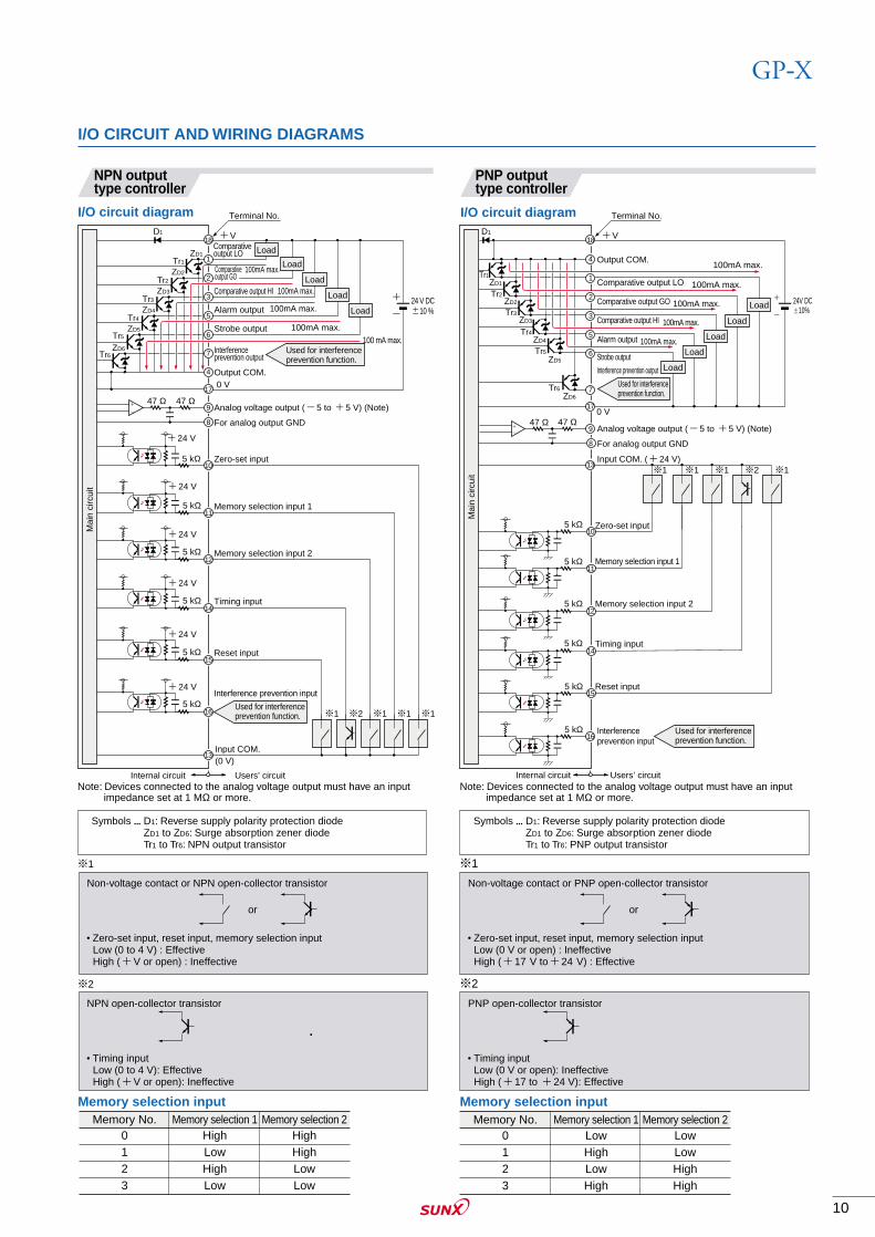
Memory selection 1LowHighLowHigh
Memory selection 2LowLowHighHigh
Memory No.0123
Memory selection 1HighLowHighLow
Memory selection 2HighHighLowLow
I/O circuit diagram
I/O CIRCUIT AND WIRING DIAGRAMS
NPN output type controller
V
Terminal No.
Comparative output LO
0 V
Comparative output HI
Alarm output
Strobe output
Interferenceprevention output
Output COM.
D1
100mA max.Tr1
100mA max.
ZD1
18
1
2
3
5
4
9
17
8
10
11
12
14
15
Tr2ZD2
Tr3ZD3
Tr4ZD4
Tr5ZD5
ZD6Tr6
100mA max.
100mA max.6
7
16
13
Load
Load
Load
Load
Load
Used for interferenceprevention function.
Comparative output GO
47 Ω47 Ω
24 V
5 kΩ
24 V
24 V
24 V
5 kΩ
5 kΩ
5 kΩ
24 V
5 kΩ
24 V
5 kΩ Used for interferenceprevention function.
Analog voltage output (5 to 5 V) (Note)
For analog output GND
Memory selection input 1
Memory selection input 2
Interference prevention input
Zero-set input
Timing input
Reset input
Users’ circuitInternal circuit
Input COM.(0 V)
m1 m2 m1m1 m1
100 mA max.
24 V DC10 %
D1
24V DC10%
Tr1ZD1
18
4
1
2
3
7
9
17
8
10
11
12
14
15
Tr2ZD2
Tr3ZD3
Tr4ZD4
Tr5
ZD6
ZD5
Tr6
5
6
16
13
47 Ω47 Ω
5 kΩ
5 kΩ
5 kΩ
5 kΩ
5 kΩ
5 kΩ
0 V
Used for interferenceprevention function.
Analog voltage output (5 to 5 V) (Note)
For analog output GND
Input COM. (24 V)
V
Terminal No.
Comparative output LO
Comparative output GO
Comparative output HI
Alarm output
Strobe output
Interference prevention output
Output COM.100mA max.
100mA max.
100mA max.
100mA max.
100mA max.
m1m1 m1 m2 m1
Memory selection input 1
Memory selection input 2
Used for interferenceprevention function.
Interferenceprevention input
Timing input
Reset input
Zero-set input
Users’ circuitInternal circuitNote: Devices connected to the analog voltage output must have an input
impedance set at 1 MΩ or more.Note: Devices connected to the analog voltage output must have an input
impedance set at 1 MΩ or more.
Symbols D1: Reverse supply polarity protection diode ZD1 to ZD6: Surge absorption zener diodeTr1 to Tr6: NPN output transistor
Symbols D1: Reverse supply polarity protection diode ZD1 to ZD6: Surge absorption zener diodeTr1 to Tr6: PNP output transistor
Non-voltage contact or NPN open-collector transistor
• Zero-set input, reset input, memory selection inputLow (0 to 4 V) : EffectiveHigh (V or open) : Ineffective
NPN open-collector transistor
• Timing inputLow (0 to 4 V): EffectiveHigh (V or open): Ineffective
PNP open-collector transistor
• Timing inputLow (0 V or open): Ineffective High (17 to 24 V): Effective
or
Non-voltage contact or PNP open-collector transistor
• Zero-set input, reset input, memory selection inputLow (0 V or open) : IneffectiveHigh (17 V to24 V) : Effective
or
Memory selection input Memory selection input
Mai
n ci
rcui
t
Mai
n ci
rcui
t
Load
Load
Load
Load
Load
m1
m2
PNP output type controller
I/O circuit diagram
GP-X
11
1
2
3
4
6
7
8
9
0
A
B
C
5 D
E
F
G
H
1
2
3
4
5
6
7
8
9
0
A
B
C
D
E
F
G
H
I
J
K
L
M
N
O
A0B0C0D0A1B1C1D1A2B2C2D2A3B3C3D3A4B4C4D4
POLE
VALID
HOLD
GNDGND
123456789
0ABCDEFGH
2524
2322
2120
1918
1716
1514
1312
1110
98
76
54
32
1
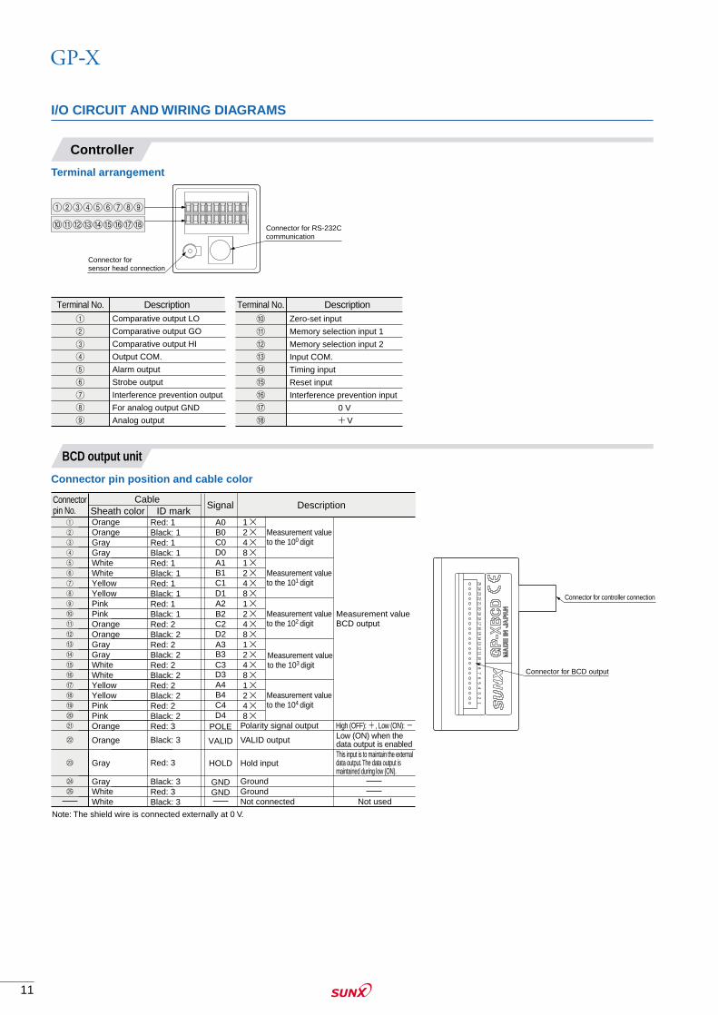
I/O CIRCUIT AND WIRING DIAGRAMS
Controller
Terminal arrangement
Connector for sensor head connection
Connector for RS-232C communication
Terminal No. DescriptionComparative output LO
Comparative output GO
Comparative output HI
Output COM.
Alarm output
Strobe output
Interference prevention output
For analog output GND
Analog output
Terminal No. DescriptionZero-set input
Memory selection input 1
Memory selection input 2
Input COM.
Timing input
Reset input
Interference prevention input
BCD output unit
Connector pin position and cable color
Connectorpin No. Sheath color ID mark
Cable
OrangeOrangeGrayGrayWhiteWhiteYellowYellowPinkPinkOrangeOrangeGrayGrayWhiteWhiteYellowYellowPinkPinkOrange
Orange
Gray
GrayWhiteWhite
Red: 1Black: 1Red: 1Black: 1Red: 1Black: 1Red: 1Black: 1Red: 1Black: 1Red: 2Black: 2Red: 2Black: 2Red: 2Black: 2Red: 2Black: 2Red: 2Black: 2Red: 3
Black: 3Red: 3Black: 3
Black: 3
Red: 3
Signal Description
12481248124812481248
Measurement value to the 100 digit
Measurement value to the 101 digit
Measurement value to the 102 digit
Measurement value to the 103 digit
Measurement value to the 104 digit
GroundGroundNot connected
Polarity signal output
VALID output
Hold input
Measurement value BCD output
Not used
Connector for controller connection
Connector for BCD output
High (OFF): , Low (ON): Low (ON) when the data output is enabledThis input is to maintain the external data output. The data output is maintained during low (ON).
Note: The shield wire is connected externally at 0 V.
0 V
V

GP-X
12
Mounting with set screw
This sensor is a CE conformity product complying with EMC Directive. The harmonized standard with regard to immunity that applies to this product is EN 61000-6-2 and the following conditions must be met to conform to that standard.
•
The controller should be connected less than 10 m 32.808 ft from the power supply.The signal line to connect with the controller should be less than 30 m 98.425 ft.A ferrite clamp must be mounted within 10 mm 0.394 in from connector fitted onto the GP-XBCC3 cable with connector on one end for BCD output units.The EN 50082-2 that previously applied to the products for conforming to EMC Directive was replaced by EN 61000-6-2 starting April 1st. 2002.
•
•
•
6 0.236 8 0.31512 0.47212 0.47225 0.984
16 0.630 16 0.630 50 1.969 50 1.969 55 2.165
30 1.181 165 6.496
A
F
E
GP-X10M
<GP-X10M>
GP-X12MLGP-X22KL
<GP-X12ML> <GP-X22KL>
Distance from surrounding metal
<Embedding of the sensor head in metal>
DC GP-X3SE
GP-X5SEGP-X8S
3 0.118
GP-X10MGP-X12MLGP-X22KL
14 0.551
GP-X3SEGP-X5SEGP-X8SGP-X10MGP-X12ML
GP-X3SEGP-X5SEGP-X8S
GP-X10MGP-X12MLGP-X22KL
1
?
t
Conditions in use for CE conformity
In case the sensing object is disc-shaped or cylindrical, the linearity varies with the sensing object size.In the event the sensing object is larger than the sizes indicated in the table below, the linearity specification (within 0.3 % F.S.) is satisfied by performing zero-adjustment and span adjustment when in contact using the scaling function.
•
Linearity in case of disc-shaped or cylindrical objects
Cylinder diameter " (mm in)Sensor head Disc diameter " (mm in)
<In case of cylinder><In case of disc>
Iron discIron cylinder
" (mm in)
t : 1 mm 0.039 in # : 135 mm 5.315 in
Set screw (M3 or less)
(Cup-point)
Model No. A (mm in) Tightening torque
4 to 16 0.157 to 0.630
5 to 16 0.197 to 0.630
0.10 N m or less
0.44 N m or less
0.58 N m or less
Mounting with nut
Attached toothed lock washer
Mounting plate Mounting plate Mounting plate
Model No. B (mm in) Tightening torque
9.8 N m or less
20 N m or less
20 N m or less
7 0.276 or more
14 0.551 or more
20 0.787 or more (Note 1)
Metal
D (mm in)Sensor head C (mm in)
"10 "0.394
"18 "0.709"14 "0.551"50 "1.969
20 0.787"50 "1.969
Mutual interference
<Face to face mounting>
<Parallel mounting>
F (mm in)Sensor head E (mm in)
30 1.181
15 0.591
40 1.57540 1.575170 6.693
11 0.433
9 0.354
15 0.591 15 0.591 50 1.969
GP-X22KL 200 7.874 200 7.874
Correction coefficient
Sensor head
Metal
Stainless steel (SUS304), Iron
Aluminum 0.5 approx.
GP-X5SEGP-X8S
GP-X3SE
GP-X3SEGP-X5SEGP-X8SGP-X10MGP-X12MLGP-X22KL
Conditions
" mmin( (
The tightening torque should be under the value given below. •
Make sure to use an M3 or smaller set screw having a cup-point. •
Mounting sensor head The sensing range is specified for the standard sensing object [stainless steel (SUS304) / iron [Cold rolled carbon steel (SPCC)], 6060t 1 mm 2.3622.362t 0.039 in]. For sensing metals other than the standard sensing objects, use the correction coefficient stated below as a guideline. Verify with the actual sensor before using.
•
Sensing range
If several sensor heads are mounted close together, some specifications may not be satisfied. Therefore, proceed with the interference prevention function enabled.The interference prevention function eliminates interference among sensors by alternating sensor oscillations. Contact our office for details about time charts etc.If not using the interference prevention function, leave a distance more than the values given below.
•
As metal around the sensor may affect the sensing performance, pay attention to the following points.
Since the analog output may change if the sensor head is completely embedded in metal, keep the minimum distance specified in the table below.
•
•
B
Attached toothed lock washer
B B
Attached toothed lock washer
Notes: 1) Without nut. If a nut is installed, the dimension will be 23.5 mm or more.
2) Mount such that the nuts do not protrude from the threaded portion.
This product is not a safety sensor. Its use is not intended or designed to protect life and prevent body injury or property damage from dangerous parts of machinery. It is a normal object detection sensor.
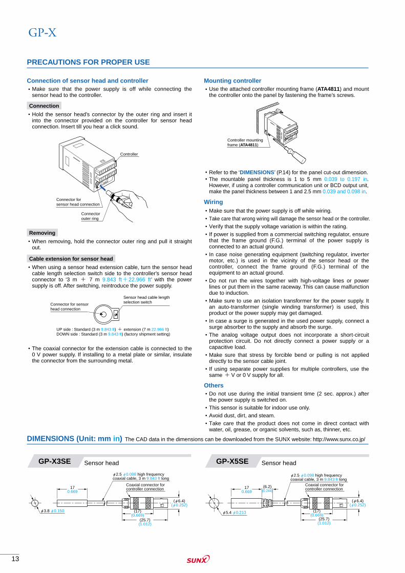
PRECAUTIONS FOR PROPER USE
The sensor head and the controller are adjusted in order to conform to the default specification linearity.In the event of replacing sensor heads, input the sensor head’s characteristic code and conduct 3-point correction (calibration).Should you use an extension cable, turn the sensor head cable length selection switch located on the back of the controller to‘3 m + 7 m 9.843 ft + 22.966 ft’. Then reintroduce the power supply and conduct 3-point correction (calibration).
•
•
•
GP-X
13
PRECAUTIONS FOR PROPER USE
Wiring
Connection
Removing
Cable extension for sensor head
Controller
Connector for sensor head connection
Connector outer ring
Sensor head cable length selection switch
UP side : Standard (3 m 9.843 ft) extension (7 m 22.966 ft)DOWN side : Standard (3 m 9.843 ft) (factory shipment setting)
Controller mounting frame (ATA4811)
DIMENSIONS (Unit: mm in) The CAD data in the dimensions can be downloaded from the SUNX website: http://www.sunx.co.jp/
Sensor head Sensor head
"2.5 "0.098 high frequency coaxial cable, 3 m 9.843 ft long
(25.7)(1.012)
("6.4)("0.252)
170.669
"3.8 "0.150 (17)(0.669)
"2.5 "0.098 high frequency coaxial cable, 3 m 9.843 ft long
(6.2)(0.244)
"5.4 "0.213
("6.4)("0.252)
(25.7)(1.012)
(17)(0.669)
Make sure that the power supply is off while connecting the sensor head to the controller.
•
Connection of sensor head and controllerUse the attached controller mounting frame (ATA4811) and mount the controller onto the panel by fastening the frame’s screws.
•
Refer to the ‘DIMENSIONS’ (P.14) for the panel cut-out dimension.The mountable panel thickness is 1 to 5 mm 0.039 to 0.197 in. However, if using a controller communication unit or BCD output unit, make the panel thickness between 1 and 2.5 mm 0.039 and 0.098 in.
Mounting controller
Do not use during the initial transient time (2 sec. approx.) after the power supply is switched on.This sensor is suitable for indoor use only.Avoid dust, dirt, and steam.Take care that the product does not come in direct contact with water, oil, grease, or organic solvents, such as, thinner, etc.
•
•
•
•
Others
Make sure that the power supply is off while wiring.Take care that wrong wiring will damage the sensor head or the controller.Verify that the supply voltage variation is within the rating.If power is supplied from a commercial switching regulator, ensure that the frame ground (F.G.) terminal of the power supply is connected to an actual ground.In case noise generating equipment (switching regulator, inverter motor, etc.) is used in the vicinity of the sensor head or the controller, connect the frame ground (F.G.) terminal of the equipment to an actual ground.Do not run the wires together with high-voltage lines or power lines or put them in the same raceway. This can cause malfunction due to induction.Make sure to use an isolation transformer for the power supply. It an auto-transformer (single winding transformer) is used, this product or the power supply may get damaged.In case a surge is generated in the used power supply, connect a surge absorber to the supply and absorb the surge.The analog voltage output does not incorporate a short-circuit protection circuit. Do not directly connect a power supply or a capacitive load.Make sure that stress by forcible bend or pulling is not applied directly to the sensor cable joint.If using separate power supplies for multiple controllers, use the same V or 0 V supply for all.
•
•
•
•
•
•
•
•
•
•
•
•
•
Connector for sensor head connection
Hold the sensor head’s connector by the outer ring and insert it into the connector provided on the controller for sensor head connection. Insert till you hear a click sound.
•
When removing, hold the connector outer ring and pull it straight out.
•
When using a sensor head extension cable, turn the sensor head cable length selection switch side to the controller’s sensor head connector to ‘3 m 7 m 9.843 ft22.966 ft’ with the power supply is off. After switching, reintroduce the power supply.
•
The coaxial connector for the extension cable is connected to the 0 V power supply. If installing to a metal plate or similar, insulate the connector from the surrounding metal.
•
Coaxial connector forcontroller connection 17
0.669
Coaxial connector forcontroller connection
GP-X3SE GP-X5SE
GP-X
14
GP-X8S GP-X10M
GP-X12ML GP-X22KL
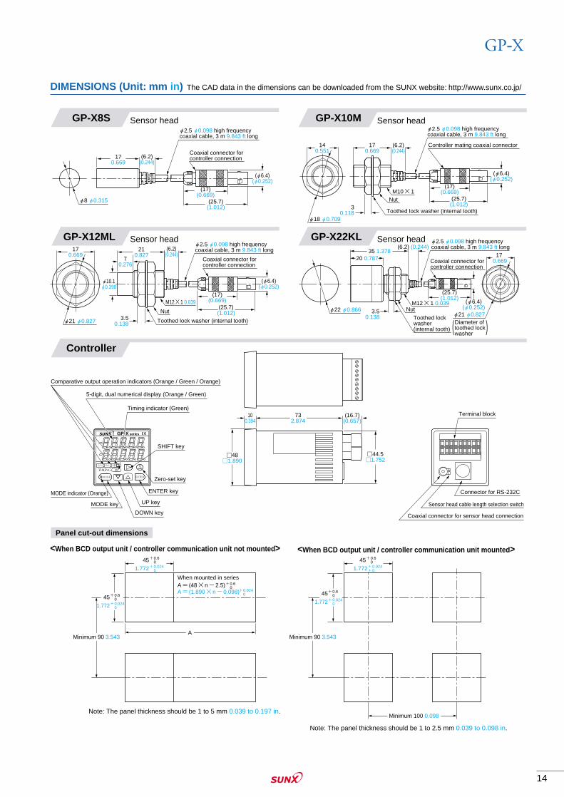
DIMENSIONS (Unit: mm in) The CAD data in the dimensions can be downloaded from the SUNX website: http://www.sunx.co.jp/
Sensor head Sensor head
Sensor head Sensor head
M101Nut
30.118
170.669
(6.2)(0.244)
"2.5 "0.098 high frequency coaxial cable, 3 m 9.843 ft long
Controller mating coaxial connector
Toothed lock washer (internal tooth)
(25.7)(1.012)
(17)(0.669)
"2.5 "0.098 high frequency coaxial cable, 3 m 9.843 ft long
170.669
"8 "0.315
(6.2)(0.244)
(25.7)(1.012)
(17)(0.669)
Controller
Terminal block
Connector for RS-232C
Sensor head cable length selection switch
Panel cut-out dimensions
<When BCD output unit / controller communication unit not mounted> <When BCD output unit / controller communication unit mounted>
AMinimum 90 3.543
450.60
1.7720.0240
450.60
1.7720.0240
450.60
1.7720.0240
A(48n2.5)0.60
A(1.890n0.098)0.0240
When mounted in series
Minimum 90 3.543
Minimum 100 0.098Note: The panel thickness should be 1 to 5 mm 0.039 to 0.197 in.
Note: The panel thickness should be 1 to 2.5 mm 0.039 to 0.098 in.
Coaxial connector forcontroller connection
("6.4)("0.252)
"18 "0.709
140.551
"10.1"0.398
210.827
(6.2)(0.244)
170.669
("6.4)("0.252)
("6.4)("0.252)
"21 "0.827
"2.5 "0.098 high frequency coaxial cable, 3 m 9.843 ft long
"2.5 "0.098 high frequency coaxial cable, 3 m 9.843 ft long
70.276
3.50.138
(17)(0.669)M121 0.039
Nut
Toothed lock washer (internal tooth)
(25.7)(1.012)
Coaxial connector forcontroller connection
Coaxial connector forcontroller connection
GP-X
SHIFT key
UP key
DOWN key
series
Comparative output operation indicators (Orange / Green / Orange)
Zero-set key
ENTER key
MODE key
MODE indicator (Orange)
5-digit, dual numerical display (Orange / Green)
Timing indicator (Green)
481.890
732.874
100.394
(16.7)(0.657)
44.51.752
Coaxial connector for sensor head connection
450.60
1.7720.0240
Toothed lock washer (internal tooth)
Nut"22 "0.866"21 "0.827Diameter of toothed lock washer
35 1.37820 0.787
3.50.138
("6.4)("0.252)
(6.2) (0.244)
17 0.669
M121 0.039
(25.7)(1.012)
( )

DIMENSIONS (Unit: mm in) The CAD data in the dimensions can be downloaded from the SUNX website: http://www.sunx.co.jp/
BCD output unit (Optional)
Assembly dimensions with controller
Assembly dimensions with controller
(8.5)(0.335)
552.165
Controller communication unit (optional)
Terminator switch
Connector for communication
401.575
552.165
401.575
GP-XBCD
GP-XCOM
Connector for controller connection
Connector for BCD output
200.787
(27.8)(1.094)
(68)(2.677)
(68)(2.677)
1 to 2.50.039 to 0.098
(74.6)(2.937)
Connector for BCD output
Mounting bracket
BCD output unit
Controller
Panelthickness
Mountingframe
Cable with connector for BCD output unit
Connector for controller connection
200.787
ControllerMounting bracket
1 to 2.50.039 to 0.098 (74.6)
(2.937)(68)
(2.677)
(68)(2.677)
Connector forcommunication
Terminator switch
Panelthickness
Mountingframe
Communication unit
Communication cable(8.5)
(0.335)
No. CE-GPX-7 May, 2003
2431-1 Ushiyama-cho, Kasugai-shi, Aichi, 486-0901, JapanPhone: +81-(0)568-33-7211FAX: +81-(0)568-33-2631
SUNX Limited
Phone: +81-(0)568-33-7861FAX: +81-(0)568-33-8591
Overseas Sales Dept.
Printed on 100% recycled paper PRINTED IN JAPAN
http://www.sunx.co.jp/
All information is subject to change without prior notice.


![CR-1 : @TAWAS B LIB.TAWAS B(SCH 1):PAGE1 TAWASnotebookschematic.org/data/NOTEBOOK/attachments/SC... · resume gp[6] gp[7] gp[8] gp[9] 3.3v 3.3v 3.3v 3.3v gp[23] gp[24] gp[25] gp[26]](https://img.pdfslide.us/doc/110x75/5f812ff679030c23f20de0bd/cr-1-tawas-b-libtawas-bsch-1page1-ta-resume-gp6-gp7-gp8-gp9-33v.jpg)


![MOTOMAN GP-Series · (minimizes L-U axis offset) ... L U View A View B View C MOTOMAN GP-Series Specifications GP12 Axes Maximum motion range [º] Maximum speed [º/sec.]](https://img.pdfslide.us/doc/110x75/5b0354577f8b9a8c688bfb79/motoman-gp-series-minimizes-l-u-axis-offset-l-u-view-a-view-b-view-c-motoman.jpg)