Embed Size (px)
Citation preview
5/12/2018 High Speed Craft Rusa - slidepdf.com
http://slidepdf.com/reader/full/high-speed-craft-rusa 1/167
RUSSIAN MARITIME REGISTER OF SHIPPING
RULESFOR THE CLASSIFICATION AND CONSTRUCTION
OF HIGH-SPEED CRAFT
St. Petersburg2008
ND N 2-020101-054-E

5/12/2018 High Speed Craft Rusa - slidepdf.com
http://slidepdf.com/reader/full/high-speed-craft-rusa 2/167
8.3.36
LIST OF CIRCULAR LETTERS AMENDING/SUPPLEMENTING NORMATIVE
DOCUMENT
(Normative document No. and title)
ItemNo.
Circular letter No.,date of approval
List of amended andsupplemented paras
11/05
Reset form
1. 010-6.2 МК-419ц dated 19.10.09 Part XVI: 2.1.2.
Rules for classification and construction of high-speed craft (2008)
ND No. 2-020101-054-E

5/12/2018 High Speed Craft Rusa - slidepdf.com
http://slidepdf.com/reader/full/high-speed-craft-rusa 3/167
Rules for the Classification and Construction of High-Speed Craft have been approved in accordance withthe current Regulations and came into force on 1 Fedruary 2009.
The Rules have been developed on the basis of IMO International Code of Safety for High-Speed Craft(Resolution MSC.97(73), Resolution MSC.205(81), Resolution MSC.222(82)).
ISBN 978-5-89331-076-4 >AA89A:89 <>@A:>9 @538AB@ AC4>E>4AB20 , 2008

5/12/2018 High Speed Craft Rusa - slidepdf.com
http://slidepdf.com/reader/full/high-speed-craft-rusa 4/167
GENERAL
1 Scope of application . . . . . . . . . . . . 62 Definitions and explanations . . . . . . . . 63 Conditions of safety . . . . . . . . . . . . 84 General requirements . . . . . . . . . . . . 95 Documents . . . . . . . . . . . . . . . . . 9
PART I. CLASSIFICATION
1 General . . . . . . . . . . . . . . . . . . 102 Class notation of craft . . . . . . . . . . 103 Classification surveys of craft. . . . . . . 114 Classification of high-speed craft with class
of another classification society . . . . . . 115 Technical documentation . . . . . . . . . 11
PART II. HULL STRUCTURE AND STRENGTH
1 General . . . . . . . . . . . . . . . . . . 212 Hull design principles. . . . . . . . . . . 253 Requirements for hydrofoil installation
design . . . . . . . . . . . . . . . . . . 434 Requirements for flexible skirt design. . . 46
5 Strength norms . . . . . . . . . . . . . . 47
PART III. ARRANGEMENTS, EQUIPMENT AND OUTFIT
1 General . . . . . . . . . . . . . . . . . . 792 Rudder and steering gear . . . . . . . . . 793 Anchor arrangement . . . . . . . . . . . 804 Mooring and towing arrangements . . . . 815 Signal masts . . . . . . . . . . . . . . . 826 Arrangement and closure of openings
in hull, superstructures and deckhouses . . 827 Arrangements and equipment
of craft spaces. Means of escape . . . . . 828 Guard rails, bulwarks. . . . . . . . . . . 869 Emergency outfit . . . . . . . . . . . . . 86A p p e n d i x . Criteria for testing and evaluation
of revenue and crew seats. . . . . . . . . 87
PART IV. STABILITY
1 Scope of application . . . . . . . . . . . 892 Definitions and explanations . . . . . . . 893 General technical requirements . . . . . . 89
4 Inclining and stability information . . . . . 905 Departures from the Rules . . . . . . . . . 91
6 Conditions of sufficient stability . . . . . . 917 Passage of craft from one port to another . 928 General requirements for stability . . . . . 929 Static stability curve . . . . . . . . . . . . 9310 Metacentric height . . . . . . . . . . . . . 9311 Allowance for icing . . . . . . . . . . . . 9312 Stability in service . . . . . . . . . . . . . 9313 Additional requirements for stability . . . . 94A p p e n d i x 1 . Determination of assumed design
moment at which high-speed craft losesoperational mode . . . . . . . . . . . . 100
A p p e n d i x 2 . Icing as applied to all typesof craft. . . . . . . . . . . . . . . . . . 100
PART V. RESERVE OF BUOYANCY AND SUBDIVISION
1 General . . . . . . . . . . . . . . . . . 1022 Intact buoyancy . . . . . . . . . . . . . 1023 Freeboard . . . . . . . . . . . . . . . . 1064 Subdivision . . . . . . . . . . . . . . . 107
PART VI. FIRE PROTECTION
1 General . . . . . . . . . . . . . . . . . 1132 Structural fire protection. . . . . . . . . 1143 Fire fighting equipment and systems . . . 1194 Fire detection and alarm systems. . . . . 1215 Fire outfit and spare parts . . . . . . . . 1226 Open ro-ro spaces . . . . . . . . . . . . 1237 Craft and cargo spaces intended
for the carriage of dangerous goods . . . 123
PART VII. MACHINERY INSTALLATIONS
1 General . . . . . . . . . . . . . . . . . 1242 Power output of main machinery . . . . 1243 Control stations . . . . . . . . . . . . . 1244 Spare parts . . . . . . . . . . . . . . . . 125
PART VIII. SYSTEMS AND PIPING
1 General . . . . . . . . . . . . . . . . . 1252 Bilge system . . . . . . . . . . . . . . . 1263 Ballast system . . . . . . . . . . . . . . 127
C O N T E N T S

5/12/2018 High Speed Craft Rusa - slidepdf.com
http://slidepdf.com/reader/full/high-speed-craft-rusa 5/167
4 Ventilation systems . . . . . . . . . . . . 1275 Oil fuel system . . . . . . . . . . . . . . 1296 Lubricating oil system . . . . . . . . . . 1307 Compressed air system . . . . . . . . . . 130
8 Exhaust gas system . . . . . . . . . . . . 1309 Cooling water system . . . . . . . . . . . 13010 Hydraulic system . . . . . . . . . . . . . 13111 Air, overflow and sounding piping . . . . 13112 Thermal liquid systems . . . . . . . . . . 131
PART IX. MACHINERY
1 General . . . . . . . . . . . . . . . . . . 1322 Engines . . . . . . . . . . . . . . . . . . 1323 Shafting, gears, disengaging and elastic
couplings . . . . . . . . . . . . . . . . . 1334 Propulsion and lift devices . . . . . . . . 1335 Mechanical and hydraulic drives . . . . . 133
PART X. BOILERS, HEAT EXCHANGERS AND PRESSURE
VESSELS
1 General . . . . . . . . . . . . . . . . . . 134
PART XI. ELECTRICAL EQUIPMENT
1 General . . . . . . . . . . . . . . . . . . 1352 General requirements . . . . . . . . . . . 1353 Main source of electrical power. . . . . . 1364 Distribution of electrical power . . . . . . 1365 Emergency electrical installations . . . . . 1376 Accumulator batteries . . . . . . . . . . 1407 Cables and wires . . . . . . . . . . . . . 1408 Spare parts . . . . . . . . . . . . . . . . 140
PART XII. REFRIGERATING PLANTS
1 General . . . . . . . . . . . . . . . . . . 141
PART XIII. MATERIALS
1 General . . . . . . . . . . . . . . . . . . 141
PART XIV.WELDING
1 General . . . . . . . . . . . . . . . . . . 141
PART XV. AUTOMATION
1 General . . . . . . . . . . . . . . . . . 1412 Technical documentation. . . . . . . . . 142
3 Stabilization system . . . . . . . . . . . 1424 Craft control station . . . . . . . . . . . 1425 Automation equipment of machinery
installations . . . . . . . . . . . . . . . 1436 Alarm system . . . . . . . . . . . . . . 1437 Safety system . . . . . . . . . . . . . . 143
PART XVI. LIFE-SAVING APPLIANCES
1 General and definitions . . . . . . . . . 144
2 Communications and signal equipment . . . 1443 Personal life-saving appliances . . . . . . 1444 Emergency instructions and manuals. . . 1455 Operating instructions . . . . . . . . . . 1456 Stowage of survival craft. . . . . . . . . 1457 Survival craft and rescue boats
embarkation and recovery arrangements . . . 1468 Line-throwing appliance . . . . . . . . . 1469 Operational readiness, maintenance . . . 14610 Survival craft and rescue boats. . . . . . 14711 Helicopter pick-up areas . . . . . . . . . 14712 Open reversible liferafts . . . . . . . . . 14713 Evacuation time . . . . . . . . . . . . . 15014 Noise levels . . . . . . . . . . . . . . . 151
PART XVII. RADIO EQUIPMENT
1 Scope of application . . . . . . . . . . . 1512 Definitions and explanations . . . . . . . 1513 Scope of technical supervision . . . . . . 1514 Technical documentation. . . . . . . . . 1525 Radio installations of high-speed craft . . 1526 List of radio equipment . . . . . . . . . 1527 Arrangement of radio equipment. . . . . 152
8 Sources of power . . . . . . . . . . . . . 1539 Aerials . . . . . . . . . . . . . . . . . . 15310 Constructional and operational
requirements for radio equipment . . . . 15311 Maintenance . . . . . . . . . . . . . . . 15312 Spare parts . . . . . . . . . . . . . . . . 15313 Radio personnel . . . . . . . . . . . . . 153
PART XVIII. NAVIGATIONAL EQUIPMENT
1 Scope of application . . . . . . . . . . . 154
2 Definitions and explanations . . . . . . . 154
4 Contents

5/12/2018 High Speed Craft Rusa - slidepdf.com
http://slidepdf.com/reader/full/high-speed-craft-rusa 6/167
3 Scope of technical supervision . . . . . . 1544 Technical documentation . . . . . . . . . 1545 List of navigational equipment . . . . . . 1546 Arrangement of navigational equipment . 154
7 Sources of power . . . . . . . . . . . . . 1568 Spare parts . . . . . . . . . . . . . . . . 1569 Night vision equipment . . . . . . . . . . 15610 Craft control stations . . . . . . . . . . . 156
11 Operational requirementsfor navigational equipment. . . . . . . . 158
PART XIX. SIGNAL MEANS
1 General . . . . . . . . . . . . . . . . . 1632 Equipment of craft with signal means . . 1633 Fitting of signal means on board. . . . . 163
Contents 5

5/12/2018 High Speed Craft Rusa - slidepdf.com
http://slidepdf.com/reader/full/high-speed-craft-rusa 7/167
1 SCOPE OF APPLICATION
1.1 Rules for the Classification and Constructionof High-Speed Craft* of Russian Maritime Registerof Shipping** apply to:
.1 passenger ships of whatever gross tonnagewhich in the course of their voyage do not proceedmore than 4 h distance at operational speed from aplace of refuge in fully loaded condition;
.2 cargo ships of 500 gross tonnage and over
which in the course of their voyage do not proceedmore than 8 h distance at operational speed from aplace of refuge in fully loaded condition;
.3 self-propelled ships not specified in 1.1.1 and1.1.2 with power output of their main engines 55 kWand over.
1.2 Rules for Safety of Dynamically SupportedCraft, 1990, apply to non-self-propelled air-cushionplatforms with power output of their main engines55 kW and over.
1.3 The scope of requirements for ships referredto in 1.1.3 is specified by the Register in eachparticular case.
1.4 The requirements of the Rules apply to shipswhich were under construction or in service on thedate of coming into force of the Rules as far as it isreasonable and practicable.
1.5 Unless provided otherwise in the present Rules,General Regulations for the Classification and OtherActivity apply to high-speed craft *** as far as they areapplicable to such ships.
1.6 Rules for the Classification and Constructionof Sea-Going Ships and Rules for the Equipment of Sea-Going Ships apply to HSC as far as it is specifiedin each Part of the present Rules.
2 DEFINITIONS AND EXPLANATIONS
2.1 For the purpose of the present Rules thefollowing definitions have been adopted.
A d m i n i s t r a t i o n is the Government of theState the flag of which the craft is flying.
F a i l u r e m o d e a n d e f f e c t s a n a l y s i s(FMEA) is an assessment of craft systems andequipment aiming at determining whether some
rather probable failure mode may cause a hazardousor catastrophic effect to the craft made in compliancewith Annex 4 of the IMO International Code of Safety for High-Speed Craft.
B a s e p o r t is a specific port identified in theroute operational manual and provided with:
appropriate facilities providing continuous radiocommunications with craft at all times while in portsand at sea;
means for obtaining a reliable weather forecastfor the corresponding region and its due transmission
to all craft in operation;for category A craft-access to facilities providedwith appropriate rescue and survival equipment;
access to craft maintenance services with appro-priate equipment.
D e s i g n w a t e r l i n e is the waterline corre-sponding to the maximum operational weight of craftwith no lift or propulsion machinery active.
M a x i m u m o p e r a t i o n a l w e i g h t is theoverall weight up to which craft operation in theintended mode is permitted by the Administration.
D i s p l a c e m e n t o f a l i g h t c r a f t is thedisplacement of a craft in tonnes without cargo, oil
fuel, lubricating oil, ballast water, fresh water andfeed water in tanks, consumable stores, passengersand crew and their effects.
H i g h - s p e e d c r a f t is a craft capable of operating at a maximum speed, in metres per second(m/s), equal to or exceeding:
3,76D0,1667
where D _ displacement equal to the design waterline, in m3.
S i g n i f i c a n t w a v e h e i g h t is the averageheight of the one-third highest observed wave heightsover a given period.
B a s e p o r t s t a t e is the State in which thebase port is located.
L e n g t h o f c r a f t ( L ) is the overall length of the underwater watertight envelope of the rigid hull,excluding appendages, at or below the design water-line in the displacement mode with no lift orpropulsion machinery active.
F l a p is an element formed as an integrated partof, or an extension of, a foil, used to adjust thehydrodynamic or aerodynamic lift of the foil.
C o n v e n t i o n is International Convention forthe Safety of Life at Sea, 1974, as amended.
F o i l is a profiled plate or three-dimensionalconstruction at which hydrodynamic lift is generatedwhen the craft is under way.
RULES FOR THE CLASSIFICATION AND CONSTRUCTION OF HIGH-SPEED CRAFT
GENERAL
* Hereinafter referred to as "the present Rules".
**Hereinafter referred to as "the Register".***Hereinafter referred to as HSC.

5/12/2018 High Speed Craft Rusa - slidepdf.com
http://slidepdf.com/reader/full/high-speed-craft-rusa 8/167
F u l l y s u b m e r g e d f o i l is a foil having nolift components piercing the surface of the water inthe foil-borne mode.
P l a c e o f r e f u g e is any naturally or artifi-
cially sheltered aquatorium which may be used as ashelter by a craft under conditions likely to endangerits safety.
M u s t e r s t a t i o n is an area where passengerscan be gathered in case of emergency, given instruc-tions and prepared to abandon the craft, if necessary.The passenger spaces may serve as muster stations if all passengers can be instructed there and prepared toabandon the craft.
O r g a n i s a t i o n is International MaritimeOrganisation.
P a s s e n g e r is every person other than:
the Master and members of the crew or otherpersons employed or engaged in any capacity onboard a craft on the business of that craft;
a child under one year of age.A u x i l i a r y m a c h i n e r y s p a c e s are spaces
containing:diesel-generators and other essential auxiliary
machinery driven by internal combustion engines of power output up to and including 110 kW;
sprinkler, drencher or fire pumps;bilge pumps;oil filling stations;switchboards of aggregate capacity exceeding
800 kW;and trunks to such spaces (see 1.3 of Part VI
ªFire Protectionº of the present Rules).A u x i l i a r y m a c h i n e r y s p a c e s o f l i t -
t l e o r n o f i r e r i s k are spaces containing:refrigerating machinery;stabilizing systems;ventilation and air conditioning machinery;switchboards of aggregate capacity 800 kW or less;and trunks to such spaces (see 1.3 of Part VI
ªFire Protectionºof the present Rules).C a r g o s p a c e s are all spaces other than
special-category spaces and ro-ro spaces used forcargo and trunks to such spaces.
C r e w a c c o m m o d a t i o n s p a c e s arespaces allocated for the use of the crew, and includecabins, sick bays, offices, lavatories, lounges andsimilar spaces.
M a c h i n e r y s p a c e s are spaces containinginternal combustion engines with aggregate totalpower output of more than 110 kW, generators, oilfuel units, propulsion machinery, major electricalmachinery and trunks to such spaces (see 1.3 of Part VI ªFire Protectionºof the present Rules).
P u b l i c s p a c e s are spaces allocated forpassengers and include kiosks, smoke rooms, mainseating areas, lounges, dining rooms, recreation
rooms, lobbies, laboratories and similar permanentlyenclosed spaces allocated for passengers.
O p e n v e h i c l e s s p a c e s are spaces:to which any passengers carried have access;
intended for carriage of motor vehicles with fuelin their tanks for their own propulsion;
either open at both ends or open at one end andprovided with adequate natural ventilation effectiveover their entire length through permanent openingsin the side plating or deckhead, or from above.
O p e n r o - r o s p a c e s are those ro-ro spaces:to which any passengers carried have access; andeither:are open at both ends orhave an opening at one end and provided with
permanent openings distributed in the side plating or
deckhead or from above, having total area of at least10 per cent of the total area of the space sides.R o - r o s p a c e s are spaces not normally sub-
divided in any way and normally extending to either asubstantial length or the entire length of the craft inwhich motor vehicles with fuel in their tanks for theirown propulsion and/or goods (packaged or in bulk, in oron rail or road cars, vehicles (including road or rail tan-kers), trailers, containers, pallets, demountable tanks orin or on similar stowage units or other receptacles) canbe loaded or unloaded, normally in horizontal direction.
S e r v i c e s p a c e s are enclosed spaces used forpantries containing food-warming equipment but no
cooking facilities with exposed heating surfaces,lockers, sales shops, store-rooms and enclosedbaggage rooms.
Such spaces containing no cooking appliancesmay contain:
.1 coffee automats, toasters, dish washers, micro-wave ovens, water boilers and similar appliances,each of them with the maximum power of 5 kW; and
.2 electrically heated cooking plates and hotplates for keeping food warm, each of them with themaximum power of 2 kW and a surface temperaturenot above 150 8C.
S p e c i a l c a t e g o r y s p a c e s are those en-closed ro-ro spaces to which passengers have access.Special category spaces may be accommodated onmore than one deck provided that the total overallarea clear height for vehicles does not exceed 10 m.
O p e r a t i n g s t a t i o n is a confined area of thecontrol station equipped with necessary means fornavigation, manoeuvring and communication, andfrom where the functions of navigating, manoeuvringand communication, commanding, conning andlookout are carried out.
C o n t i n u o u s l y m a n n e d c o n t r o l s t a -t i o n is a control station which is continuouslymanned by a responsible member of the crew whilethe craft is in normal service.
General 7

5/12/2018 High Speed Craft Rusa - slidepdf.com
http://slidepdf.com/reader/full/high-speed-craft-rusa 9/167
C o n t r o l s t a t i o n s are spaces in which thecraft radio or navigating equipment or the emergencysource of power and emergency switchboard arelocated, or where the fire recording or fire control
equipment is centralized, or where other functionsessential to the safe operation of the craft, such aspropulsion control, public address, stabilizationsystems, etc, are located.
D i s p l a c e m e n t m o d e is the regime,whether at rest or in motion, when the weight of the craft is fully or predominantly supported byhydrostatic forces.
N o n - d i s p l a c e m e n t m o d e is the normaloperational regime of a craft when non-hydrostaticforces substantially or predominantly support theweight of the craft.
T r a n s i t i o n a l m o d e is the regime betweendisplacement and non-displacement modes.O p e r a t i n g c om p a r t m e n t is the enclosed
area from which the navigation and control of thecraft is exercised.
M a x i m u m s p e e d is the speed achieved atthe maximum continuous propulsion power atmaximum operational weight and in smooth water.
O p e r a t i o n a l s p e e d is 90 per cent of themaximum speed.
C a r g o s h i p is any high-speed craft other thana passenger ship, which is capable of maintaining themain functions and safety systems of unaffected
spaces after damage in any one compartment onboard.
C a t e g o r y A c r a f t is any high-speed pas-senger craft:
operating on a route where it has been demon-strated to the satisfaction of the Flag and Port Statesthat there is a high probability that, in the event of anevacuation at any point of the route, all passengersand crew can be rescued safely within the least of:
the time to prevent persons in survival craft fromexposure causing hypothermia in the worst intendedconditions;
the time appropriate with respect to environ-mental conditions and geographical features of theroute;
4 hours;carrying not more than 450 passengers.C a t e g o r y B c r a f t is any high-speed passen-
ger craft, other than a category A craft, withmachinery and safety systems arranged so that, inthe event of damage or flooding disabling anyessential machinery and safety systems in onecompartment, the craft retains the capability tonavigate safely.
A i r - c u s h i o n v e h i c l e ( A C V ) is a craftsuch that the whole or a significant part of its weightcan be supported, whether at rest or in motion, by a
continuously generated cushion of air dependent forits effectiveness on the proximity of the surface overwhich the craft operates.
P a s s e n g e r s h i p is a ship which carries more
than twelve passengers.H y d r o f o i l is a craft which is supported above
the water surface in non-displacement mode byhydrodynamic forces generated on foils.
R o - r o c r a f t is a craft fitted with one or morero-ro spaces.
A i r - c u s h i o n v e h i c l e s i d e - w a l l c r a f tis an air-cushion vehicle which cushion shalltally orpartially retained by permanently immersed hardstructures.
S p e c i a l - p u r p o s e s h i p is a mechanicallyself-propelled ship which by reason of its function
carries on board more than 12 persons of specialpersonnel including passengers.F l a s h p o i n t is a flashpoint determined by a test
using the closed-cup apparatus referenced in Interna-tional Maritime Dangerous Goods (IMDG) Code.
C r i t i c a l d e s i g n c o n d i t i o n s are thelimiting specified conditions, chosen for designpurposes, which the craft shall keep in a displacementmode. Such conditions shall be more severe than theworst intended conditions by a suitable margin toprovide for adequate safety in the survival condition.
W o r s t i n t e n d e d c o n d i t i o n s are thespecified environmental conditions within which the
operation of the craft is intended. This shall take intoaccount such parameters as the worst conditions of wind force allowable, significant wave height (includ-ing unfavourable combinations of length and direc-tion of waves), minimum air temperature, visibilityand depth of water for safe operation and such otherparameters as the Register may require in consideringthe type of the craft in the area of operation.
O i l f u e l u n i t is the equipment used for thepreparation of oil fuel for delivery to an oil-firedboiler, or equipment used for the preparation fordelivery of heated oil fuel to an internal combustion
engine, and includes any oil fuel pressure pumps,filters and heaters dealing with oil fuel at a pressureof more than 0,18 N/mm2.
B r e a d t h o f a c r a f t ( B ) is breadth, inmetres, of the broadest part of the moulded water-tight envelope of the rigid hull, excluding appendagesat or below the design waterline in the displacementmode with no lift or propulsion machinery active.
3 CONDITIONS OF SAFETY
3.1 The required level of safety of HSC in serviceis provided by fulfilment of the requirements of thepresent Rules regulating safety by technical means
8 Rules for the Classification and Construction of High-Speed Craft

5/12/2018 High Speed Craft Rusa - slidepdf.com
http://slidepdf.com/reader/full/high-speed-craft-rusa 10/167
provided on board of the craft in combination withorganisational and technical measures described inChapter 18 of the IMO International Code of Safetyfor High-Speed Craft* (Resolution MSC.97(73)).
A complex of organisational and technicalmeasures shall be provided by a shipowner.
3.2 Complex fulfilment of the requirements setforth in the present Rules and in Chapter 18 of theCode provides the level of safety of a HSC and onboard the craft which is equivalent to that prescribed bythe International Convention for the Safety of Life atSea and the International Convention on Load Lines.
4 GENERAL REQUIREMENTS
4.1 The first HSC of a series shall be testedaccording to a programme approved by the Register,which includes inspections in the scope which is sufficientfor confirmation of the craft reliability and safety of itsoperation under the worst intended conditions.
The programme shall provide for testing thebehaviour of HSC, its machinery and systems in caseof simulations of emergency situations, failures, errorsin control approved by the Register as well as fordetermination, if necessary, of external loads for whichstructures are calculated. Such tests shall be carried outin the presence of the Register representatives.
4.2 Based on the test results, wave height, wind
velocity under which HSC may move in thedisplacement mode in forced circumstances accord-ing to good marine practice shall be specified. Suchparameters and recommendations on control in thedisplacement mode shall be indicated in the opera-tional manual.
4.3 All cases of impairing HSC stability, i. e.abnormal angles of heel and trim, loss of controllabilityand other abnormal facts in the craft behaviour shall bereported by the shipowner to the Register RegionalOffice in charge of supervision of the craft.
4.4 Any substitution of materials, machinery, instru-
ments and other equipment subject to technical super-vision by the Register shall be agreed with the Register.
4.5 The Register may exempt HSC craft fromcomplying with some requirements of the presentRules provided it will be proved that it hindersfurther improvement of the craft. In this case, thelevel of safety not lower than that provided by thepresent Rules shall be ensured.
4.6 In case a craft where some requirement of thepresent Rules are not met is intended for interna-tional voyages, the level of safety shall be recognizedas adequate by the Register and Administration of the country at the ports of which the craft will call.
5 DOCUMENTS
5.1 Classification Certificate, Safety Equipment
Certificate, Load Line Certificate and SeaworthinessCertificate are issued by the Register to every HSCflying the RF flag.
High-Speed Craft Safety Certificate is addition-ally issued to craft engaged in international voyages.
5.2 A Permit to Operate High-Speed Craft is alsoissued to craft engaged in international commercialvoyages.
5.3 Classification Certificate is the documentwhich confirms the fulfilment of the requirements of Parts I to XV of the present Rules. The worstintended conditions under which the craft motion in
the operational mode is permitted, the maximumdistance allowed to proceed from places of refuge andother limitations, where necessary, shall be indicatedin the Classification Certificate.
5.4 Safety Equipment Certificate is the documentwhich confirms compliance with the requirements setforth in Parts XVI to XIX of the present Rules.
5.5 Load Line Certificate is the document whichconfirms compliance with the requirements of LoadLine Rules for Sea-Going Ships.
5.6 The documents referred to in 5.3, 5.4 and 5.5 areissued for five years with the annual confirmation.
5.7 Availability of the valid documents referred
to in 5.3, 5.4 and 5.5 is the ground for SeaworthinessCertificate issuance.
5.8 Seaworthiness Certificate is issued for fiveyears with the annual confirmation.
A particular route, routes or aquatorium wherethe craft is allowed to operate with due regard forweather conditions and distance allowed to proceedfrom the a place of refuge as well as other limitationsindicated in the Certificates referred to in 5.3 and 5.4shall be indicated in Seaworthiness Certificate.
5.9 Availability of the valid documents referred to in5.2 and 5.3 means the fulfilment of the Code require-
ments and gives grounds for High-Speed Craft SafetyCertificate issuance. For craft flying a foreign flag theCertificate may be issued on behalf of the Administra-tion of the country the flag of which the craft is flying.
5.10 Permit to Operate High-Speed Craft is thedocument which confirms complex fulfilment of organisational and technical measures, and opera-tional control procedures referred to in Chapter 18 of the Code by the shipowner.
5.11 The Permit is issued by the Administrationof the country the flag of which the craft is flying orby another competent organisation on behalf of theAdministration.
* Hereinafter referred to as "the Code".
General 9
5/12/2018 High Speed Craft Rusa - slidepdf.com
http://slidepdf.com/reader/full/high-speed-craft-rusa 11/167
1 GENERAL
1.1 The Register may assign a class to a craftafter construction or may assign or renew the class toa craft in service.
1.2 Assignment of the Register class means thatthe Register confirms that the craft complies with therequirements imposed thereupon and is taken underthe Register technical supervision for a specifiedperiod of time subject to annual surveys forconfirmation of the class.
1.3 Class renewal means that the Registerconfirms that the technical condition of the craft isconsistent with the class assigned and that theRegister technical supervision is prolonged for acertain period of time.
1.4 HSC class is assigned or renewed by theRegister for a period of five years but in sound cases,the Register may assign or renew the class for someother period of time.
1.5 If a craft has the valid class of the Register, itmeans that the craft is under the Register technicalsupervision, as provided in the Rules, over itstechnical condition and meets fully or to the extent
considered adequate by the Register the requirementsof the Rules applicable thereto according to thepurpose, service conditions and class notation of thecraft. The validity of the class is confirmed by thevalid Classification Certificate available on the craft.
1.6 In case a craft was not submitted to themandatory survey within the prescribed period of time; after an accident, provided it will not besubmitted for survey, in the port where the accidenttook place or at the first port the craft calls after theaccident; or after structural alterations not agreedwith the Register and changes in the craft outfit; or
after repair carried out without the Register technicalsupervision; or if the craft is operated with a draughtwhich exceeds that required by the load line or underconditions not consistent with the requirements forassigning the particular class, Classification Certifi-cate ceases to be valid, which results in withdrawal orsuspension of the class.
1.7 Where cases referred to in 1.6 are discoveredas well as in cases when the craft is taken out of service by the shipowner for a long time required tofulfil the requirements imposed by the Register forrenewal or confirmation of the class or for any otherreason, the Register Head Office may take a decisionto suspend the class for a period of up to five years.In this case survey of the craft for confirmation or
renewal of the class may be carried out only if permitted by the Register Head Office within thescope agreed with the Register.
1.8 Class withdrawal means that the Registerceases its technical supervision if renewal or suspen-sion of the class is considered impossible by theRegister. The class may also be withdrawn at theshipowner's discretion.
1.9 Class cancellation means cessation of theRegister technical supervision of the craft because of its loss or scrapping.
2 CLASS NOTATION OF CRAFT
2.1 The character of classification of a craft builtaccording to the Rules and under the Registertechnical supervision shall be KM> or KE>:
KM> for self-propelled craft;KE> for non-self-propelled air-cushion plat-
forms where machinery and equipment with poweroutput of prime movers 55 kW and over are installedsubject to technical supervision in accordance with
the Rules.2.2 Character of classification of a craft built
without the Register technical supervision.
2.2.1 If a craft as a whole or its hull or itsmachinery installation, machinery and equipmentwere built according to the Rules and under thesupervision of another classification body recognizedby the Register and then the craft was classed by theRegister, the character of classification shall be KM$
or KE$:KM$ for self-propelled craft;KE$ for non-self-propelled air-cushion plat-
forms where machinery and equipment with poweroutput of prime movers 55 kW and over are installedsubject to technical supervision in accordance withthe Rules.
2.2.2 If a craft and its machinery installation,machinery and equipment were built without thesupervision of a classification body recognized by theRegister or without the supervision of any classifica-tion body and then the craft was classed by theRegister, the character of classification shall be(KM)$ (KE)$:
(KM)$ for self-propelled craft;(KE)$ for non-self-propelled air-cushion plat-
forms where machinery and equipment with poweroutput of prime movers 55 kW and over are installed
PART I. CLASSIFICATION
10 Rules for the Classification and Construction of High-Speed Craft

5/12/2018 High Speed Craft Rusa - slidepdf.com
http://slidepdf.com/reader/full/high-speed-craft-rusa 12/167
subject to technical supervision in accordance withthe Rules.
2.3 Subdivision distinguishing marks.
2.3.1 If a craft complies with the applicable
requirements of Part V "Reserve of Buoyancy andSubdivision" of the present Rules and fully meets therequirements of Section 4 of the above-mentionedPart in case of flooding of any two or three adjacentcompartments over the entire length of the craft withthe assumed side damages specified in 4.3, subdivi-sion distinguishing mark & or /, respectively, isadded to the character of classification of the craft.
2.3.2 Distinguishing mark < may be added to thecharacter of classification only for the craft referredto in 1.1.3 and 1.2, "General" in case the Registerconsiders it possible.
2.4 Automatic stabilization mark.If an automatic or semi-automatic stabilizationsystem is installed on HSC, and the craft cannot movein the operational mode without the system, lettersAUTstab are added to the character of classification.
2.5 Designation of HSC type in the class notation.
ACV _ air-cushion vehicle.SES _ surface-effect ship.Hydrofoil craft.
SWATH _ small water area twin hull ship.MHC _ multihull craft.HSC _ high-speed craft.2.6 Descriptive notation.
A descriptive notation shows the category of thecraft and is written in the following way:
passenger craft "A" _ for category A passengership;
passenger craft "B" _ for category B passengership.
2.7 Distinguishing marks are put in the classnotation in the order given in this Section.
3 CLASSIFICATION SURVEYS OF CRAFT
3.1 Initial survey.The initial survey is carried out for the purpose of
assigning class to a craft which is submitted forclassification for the first time or for class renewal of the craft which class has been withdrawn. During theinitial survey the compliance of the craft and its technicalcondition with the present Rules shall be ascertained.
3.2 Special survey.
The special survey is carried out for the purpose of class renewal. During the special survey compliance of the technical condition of the craft with its serviceconditions defined by the craft class shall be ascertained.
3.3 Annual survey.
The annual survey is carried out for the purposeof class confirmation. The annual survey is held to
ascertain that technical condition of the craft meetsadequately the conditions of retaining the class;operation of separate machinery, arrangements andinstallations covered by the present Rules shall be
also checked.3.4 The scope of periodical surveys for HSC in
service shall be not less than that given in Table 3.4.3.5 The scope of initial survey is established by
the Register in each particular case with regard toTable 3.4.
4 CLASSIFICATION OF HIGH-SPEED CRAFT WITH CLASS
OF ANOTHER CLASSIFICATION SOCIETY
4.1 In addition to the documents listed in 5.1.3,
Part II "Carrying out Classification Survey of Ships"of the Guidelines on Technical Supervision of Ships inService, the following documents shall be submitted:
.1 longitudinal and local strength calculations;strength calculations and data on service life of hullstructures, foil arrangement and skirt; vibrationcalculations for hull, hydrofoils and skirt;
.2 calculation of external forces acting on hull,foil arrangements and skirts;
.3 geometrical and hydrodynamic scheme of foilarrangements;
.4 structural drawings of hull, foil arrangementsand their attachments in working and lifted position;
skirt and its attachment;.5 basic diagrams of automatic control and
stabilization of craft and their description;.6 drawings of stabilization controls and their
machinery;.7 drawings and characteristics of transducers in
automatic control and stabilization system;.8 drawings of lift air blowers with control
machinery and attachment;.9 torque calculations of gears to propellers and
lift air blowers or full-scale measurement results;.10 hull anti-corrosive protection system.
N o t e . Information on stability shall contain data fordisplacement, transitional and operational modes.
5 TECHNICAL DOCUMENTATION
5.1 In addition to the documents indicated inSection 3, Part I "Classification" of the Rules for theClassification and Construction of Sea-Going Shipsthe following shall be submitted for HSC.
5.1.1 Technical design.
5.1.1.1 Hull:.1 calculation of external forces;.2 longitudinal and local strength calculation;
Part I. Classification 11

5/12/2018 High Speed Craft Rusa - slidepdf.com
http://slidepdf.com/reader/full/high-speed-craft-rusa 13/167
No. Item to be surveyed
Ship survey
1.1
1.1.1
1.1.2
1.1.31.2
1.2.1
1.2.2
1.2.3
1.2.4
Underwater part of hull (outer side)1,2
Stem, bilge transom, steps, recesses, rigid structureswhich hold or divide air cushion, skirt attachmentplaces, rigid air channels and trunks, propeller shaftstruts, landing supports, hull parts by which a craft islifted, reinforcements in the area of such partsShell plating, including areas of high vibration, impactloads, foil arrangements, foil reinforcements andattachments, propeller shaft struts, angular columns,rudder stocks, foil tilting machinery, flaps, outsideplating of bridges connecting hulls
Sea valve recesses and dischargesAbove-water part of hull (outer side)2
Stem, after bulkheadShell plating, including that in the areas of foilattachments, angular columns, abutments upon abridge connecting hullsPlating of deck bounding buoyancy compartmentsPlating of deck providing longitudinal strength of craft
1 2 3 4 5 6 7 8 9
s
s
s
s
s
s
s
s
s
s
s
s
s
s
s
s
s
s
s
s
s
s
s
s
s
s
s
s
o
om3
sm3
n4
o
o
onm3
om3
s
s
s
s
s
s
s
s
s
s
s
s
s
s
o
o
s
s
o
o
o
s
s
s
s
s
s
s
1 s t a n n u a l
2 n d
a n n u a l
3 r d
a n n u a l
4 t h
a n n u a l
1 s t s p e c i a l
1 s t a n n u a l
2 n d
a n n u a l
3 r d
a n n u a l
4 t h
a n n u a l
1. Hull
SCOPE OF PERIODICAL SURVEYS OF HIGH-SPEED CRAFT
S y m b o l s :
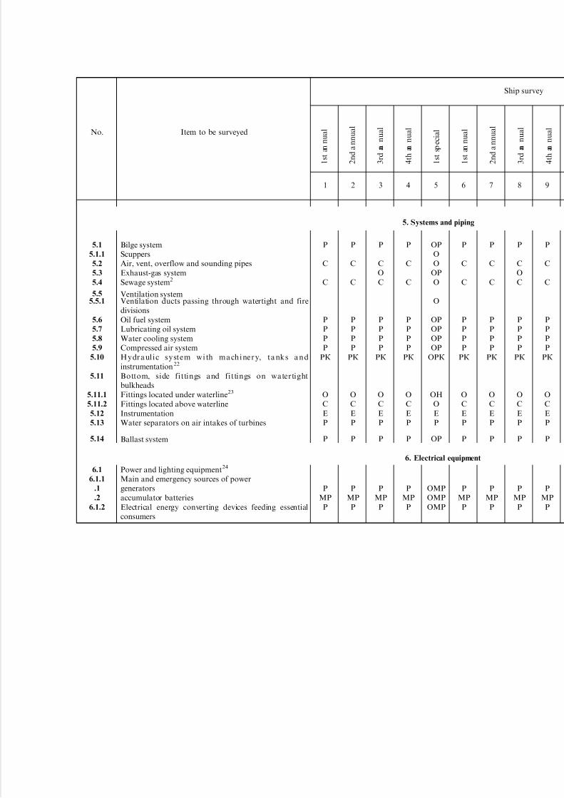
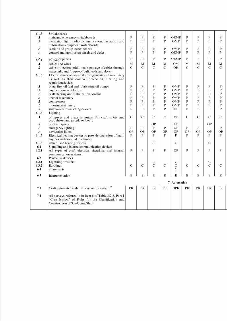
O _ examination with provision of access, opening and dismantling where necessary;C _ external examination;M _ measurements of wears, clearances, insulation resistance, etc;H _ pressure testing (hydraulic, pneumatic);P _ testing of machinery, equipment and arrangements, their external examination;E _ verification of availability of current documents and/or brands to confirm testing of instruments by appropriate competent bodies, if K _ verification of remaining service life.

5/12/2018 High Speed Craft Rusa - slidepdf.com
http://slidepdf.com/reader/full/high-speed-craft-rusa 14/167
1.2.5
1.2.6
1.2.7
1.2.8
1.3
1.3.11.3.2
1.3.3
1.3.4
1.3.5
1.3.6
1.3.7
.1
.2
1.3.8
1.3.9
1.3.10
1.4
2.12.1.1
2.2
2.2.1
2.2.2
2.2.3
2.3
2.3.1
2.3.2
2.3.32.3.4
2.3.5
2.4
2.4.1
2.4.2
Deck and bulkheads of lavatories and accumulatorbattery rooms if they bound buoyancy compartmentsSuperstructures, deckhouses (plating, decks, bulkheads)Hatch and ventilator coamingsBulwark, foil arrangements skirtSpaces inside hull5,6
Forepeak, afterpeakDry compartments, cofferdamsOil fuel and lube oil tanks7
Water tanksIndependent tanksSewage tanks8
Machinery spaces:main and auxiliary machinery spacesmain and auxiliary machinery seatingsPassenger spacesOther spaces in hull, superstructures, deckhousesAir fan trunks, air channels, receiversCorrosion protection, potential measurement2
Closing appliancesClosing appliances of hatchways and manholes of openparts of decks and inside superstructures, outer doors of superstructures and deckhouses, side scuttles, covers of ventilator cowls and openingsSteering and reverse-reduction gearRudder blade ( water, air ), flaps, steering nozzles 9
Rudder stock, rudder stock bearings, pintles,fastenings10
Steering gear (main and auxiliary) with control system,control panels and rudder blade angle indicatorsFoil arrangements and stabilization controls9
Planes, stays, flaps and other stabilization controlsAxles, bearings, pull rods of tilting flaps and foils, andother stabilization controls
Insulation of foils from hullTilting flap and foil machinery, and other stabilizationcontrols as well as connections of machinery withstabilization controlsFoil attachment and reinforcement, angular columns,foil tilting machinery, angular columns and otherstabilization controlsSkirtsSkirtSkirt attachment
s
s
s
s
oo
s
s
s
s
s
s
s
s
s
s
s
sm
r
rk
sm
sm
smrk
o
ok
o
s
s
s
s
oo
s
s
s
s
o
s
s
s
s
s
o
sm
r
rk
sm
sm
smrk
o
ok
o
s
s
s
s
oo
s
s
s
s
s
s
s
s
s
s
s
sm
r
rk
omkn
om
smrk
o
ok
o
s
s
s
s
oo
s
s
s
s
o
s
s
s
s
s
o
sm
r
rk
sm
sm
smrk
o
ok
o
om3
o
o
o
onon
on8
on8
on
on8
o
o
o
o
o
s
on
om
om
or
rk
omkn
sm
smrk
o
ok
o
s
s
s
s
oo
s
s
s
s
s
s
s
s
s
s
s
sm
r
rk
sm
sm
smrk
o
ok
o
s
s
s
s
oo
s
s
s
s
o
s
s
s
s
s
o
sm
r
rk
sm
sm
smrk
o
ok
o
o
s
s
s
oo
s
s
s
s
s
s
s
s
s
s
s
sm
r
rk
omkn
om
smrk
o
ok
o
s
s
s
s
oo
s
s
s
s
o
s
s
s
s
s
o
sm
r
rk
sm
sm
smrk
o
ok
o
2. Arrangements, equipment and outfit

5/12/2018 High Speed Craft Rusa - slidepdf.com
http://slidepdf.com/reader/full/high-speed-craft-rusa 15/167
No. Item to be surveyed
Ship survey
2.4.3
2.4.4
2.5
2.5.1
2.5.2
2.6
2.6.1
2.7
2.7.1
2.7.2
2.8
2.9
3.1
3.1.1
3.1.2
3.1.3
3.2
3.2.1
3.2.2
3.2.3
3.2.4
3.2.5
4.1
4.1.1
Skirt lifting machineryLifting machinery attachment and reinforcementAnchor arrangementAnchors, hawse pipes, chain cables, ropesStoppers and chain (rope) release devicesMooring arrangementBollards, fairleaders, ropes and other equipmentSignal mastsMasts
Standing riggingEmergency outfitWheelhouse window wiper
Structural fire protectionFire-resisting and fire-retarding divisions and closures of openings thereinSelf-closing fire doors with devices to hold them in theopen position11
Closures of outer openings (ventilation ducts, engineroom skylights, etc)11
Fire fighting systemsWater fire main, pressure water spraying, foam fire
extinguishing systemsFluid smothering system, carbon dioxide smothering9
Fire alarm systemsFire outfit, spare parts and toolsInstrumentation
Main engineMain internal combustion engine13, 14
1 2 3 4 5 6 7 8 9
rk
o
r
s
r
r
r
r
r
r
s
e
rk
rk
o
r
s
r
r
r
r
r
r
s
e
rk
rk
o
r
s
r
r
r
r
r
r
s
e
rk
rk
o
r
s
r
r
r
r
r
r
s
e
rk
rk
o
r
om
or
o
o
o
s
r
o
or
or
or
or
r
sr
e
rk
rk
o
r
s
r
r
r
r
r
r
s
e
rk
rk
o
r
s
r
r
r
r
r
r
s
e
rk
rk
o
r
s
r
r
r
r
r
r
s
e
rk
rk
o
r
s
r
r
r
r
r
r
s
e
rk
3. Fire protection
1 s t a n n u a l
2 n d
a n n
u a l
3 r d
a n n
u a l
4 t h
a n n
u a l
1 s t s p e c
i a l
1 s t a n n u a l
2 n d
a n n
u a l
3 r d
a n n
u a l
4 t h
a n n
u a l
4. Machinery installation

5/12/2018 High Speed Craft Rusa - slidepdf.com
http://slidepdf.com/reader/full/high-speed-craft-rusa 16/167
4.1.2
4.2
4.2.1
4.3
4.3.1
4.3.2
4.44.5
4.6
4.6.1
.1
.2
.3
.4
.5
4.6.2
.1
.2
.3
.4
4.6.3
.1
.2
.3
.4
4.6.4
.1
.2
.3
.4
4.7
4.7.1
4.7.2
4.7.3
.1
.2
.34.8
4.9
4.10
4.10.1
4.10.2
4.10.3
4.11
4.11.1
4.12
Gas turbineLift air blowersFixed and tilting guides with pull rodsAuxiliary machineryMain engine-driven auxiliary machineryAuxiliary internal combustion engines13, 14
InstrumentationSpare partsShafting, gears to lift air blowers and propeller15
Propeller shaft and gears shafts to lift air blowers journalsstern-tube bearingspropeller shaft glandsflanged connections and couplingsreduction gearPropeller (water and air)16
static balancing17
propeller shaft fitting (adjusting)18
propeller fastening16
pitch actuating mechanismWater-jet propeller15
propeller housing
reversing gearimpeller17
propeller shaftPropeller angular columns9,15
shaftspinionsscrewsclutch, lifting and tilting arrangementsAuxiliary machinery19
Bilge pumpFire pumpCompressorscylinders, crankshaft and main bearings, cylinder coversand valvesair coolers with fittings
safety valveSteering gearAnchor machineryTilting pylonsAngular gearsCouplings18
Tilting machineryHeat exchangers and their fittingsSafety valvesAir bottles and other pressure vessels and their fittings
rk
rk
r
rk
e
r
o
om
om
s
s
rk
s
rk
s
s
s
sk
r
r
r
rr
r
o
rk
o
rk
r
r
rk
rk
o
r
rk
e
r
o
om
om
s
o
rk
s
rk
o
om
omo
o
ok
o
r
r
r
rr
r
o
rk
o
rk
r
r
rk
rk
r
rk
e
r
o
om
om
on
s
rk
o
rk
s
s
s
sk
om
o
o
r
r
r
rr
r
o
rk
o
rk
r
r
rk
rk
r
rk
e
r
o
om
om
s
o
rk
s
rk
r
r
r
rr
r
o
rk
o
rk
r
r
rk
rk
o
or
rk
es
r
o
om
om
on
o
rk
o
rk
o
om
omo
o
ok
o
om
o
o
or
or
or
o
ror
or
o
rk
o
rk
on20r
r
on20r
rk
rk
r
rk
e
r
o
om
om
s
s
rk
s
rk
s
s
s
sk
r
r
r
rr
r
o
rk
o
rk
r
r
rk
rk
o
r
rk
e
r
o
om
om
s
o
rk
s
rk
o
om
omo
o
ok
o
r
r
r
rr
r
o
rk
o
rk
r
r
rk
rk
r
rk
e
r
o
om
om
on
s
rk
o
rk
s
s
s
sk
om
o
o
r
r
r
rr
r
o
rk
o
rk
r
r
rk
rk
r
rk
e
r
o
om
om
s
o
rk
s
rk
r
r
r
rr
r
o
rk
o
rk
r
r
5/12/2018 High Speed Craft Rusa - slidepdf.com
http://slidepdf.com/reader/full/high-speed-craft-rusa 17/167
No. Item to be surveyed
Ship survey
5.1
5.1.1
5.2
5.3
5.4
5.55.5.1
5.6
5.7
5.8
5.9
5.10
5.11
5.11.1
5.11.2
5.12
5.13
5.14
6.1
6.1.1
.1
.2
6.1.2
Bilge systemScuppersAir, vent, overflow and sounding pipesExhaust-gas systemSewage system2
Ventilation systemVentilation ducts passing through watertight and firedivisionsOil fuel systemLubricating oil systemWater cooling systemCompressed air systemHy dr a ul i c s y ste m w i th ma ch i ne r y, ta nk s a n dinstrumentation 22
Bottom, side fittings and fittings on watertightbulkheadsFittings located under waterline23
Fittings located above waterlineInstrumentationWater separators on air intakes of turbines
Ballast system
Power and lighting equipment24
Main and emergency sources of powergeneratorsaccumulator batteriesElectrical energy converting devices feeding essentialconsumers
1 2 3 4 5 6 7 8 9
r
s
s
r
r
r
r
rk
o
s
e
r
r
r
mr
r
r
s
s
r
r
r
r
rk
o
s
e
r
r
r
mr
r
r
s
o
s
r
r
r
r
rk
o
s
e
r
r
r
mr
r
r
s
s
r
r
r
r
rk
o
s
e
r
r
r
mr
r
or
o
o
or
o
o
or
or
or
or
ork
on
o
e
r
or
omr
omr
omr
r
s
s
r
r
r
r
rk
o
s
e
r
r
r
mr
r
r
s
s
r
r
r
r
rk
o
s
e
r
r
r
mr
r
r
s
o
s
r
r
r
r
rk
o
s
e
r
r
r
mr
r
r
s
s
r
r
r
r
rk
o
s
e
r
r
r
mr
r
1 s t a n
n u a l
2 n d
a n n u a l
3 r d
a n
n u a l
4 t h
a n
n u a l
1 s t s p e c i a l
1 s t a n
n u a l
2 n d
a n n u a l
3 r d
a n
n u a l
4 t h
a n
n u a l
5. Systems and piping
6. Electrical equipment
5/12/2018 High Speed Craft Rusa - slidepdf.com
http://slidepdf.com/reader/full/high-speed-craft-rusa 18/167
6.1.3
.1
.2
.3
.4
.56.1.4
.1
.2
6.1.5
.1
.2
.3
.4
.5
.6
.7
6.1.6
.1
.2
.3
.4
6.1.7
6.1.8
6.2
6.2.1
6.3
6.3.1
6.3.2
6.4
6.5
7.1
7.2
Switchboardsmain and emergency switchboardsnavigation light, radio communication, navigation andautomation equipment switchboardssection and group switchboardscontrol and monitoring panels and desks
protector panelsCablingcables and wirescable protection (additional), passage of cables throughwatertight and fire-proof bulkheads and decksElectric drives of essential arrangements and machineryas well as their control, protection, starting andregulation devicesbilge, fire, oil fuel and lubricating oil pumpsengine room ventilationcraft steering and stabilization controlanchor machinerycompressorsmooring machinerysurvival craft launching devicesLighting
of spaces and areas important for craft safety andpropulsion, and people on boardof other spacesemergency lightingnavigation lightsElectrical heating devices to provide operation of mainengines and essential machineryOther fixed heating devicesSignalling and internal communication devicesAll types of craft electrical signalling and internalcommunication systemsProtective devicesLightning arrestersEarthingSpare parts
Instrumentation
Craft automated stabilization control system22
All surveys referred to in item 6 of Table 3.2.3, Part I"Classification" of Rules for the Classification andConstruction of Sea-Going Ships
r
r
r
r
r
m
s
r
r
r
r
r
r
r
s
r
or
r
r
s
e
rk
r
r
r
r
r
m
s
r
r
r
r
r
r
r
s
r
or
r
r
s
e
rk
r
r
r
r
r
m
s
r
r
r
r
r
r
r
s
or
r
or
r
s
r
s
s
e
rk
r
r
r
r
r
m
s
r
r
r
r
r
r
r
s
r
or
r
r
s
e
rk
oemr
omr
omr
oemr
oemr
om
on
omr
omr
omr
omr
omr
omr
or
or
or
or
or
r
s
or
s
s
s
e
ork
r
r
r
r
r
m
s
r
r
r
r
r
r
r
s
r
or
r
r
s
e
rk
r
r
r
r
r
m
s
r
r
r
r
r
r
r
s
r
or
r
r
s
e
rk
r
r
r
r
r
m
s
r
r
r
r
r
r
r
s
or
r
or
r
s
r
s
s
e
rk
r
r
r
r
r
m
s
r
r
r
r
r
r
r
s
r
or
r
r
s
e
rk
7. Automation

5/12/2018 High Speed Craft Rusa - slidepdf.com
http://slidepdf.com/reader/full/high-speed-craft-rusa 19/167
No. Item to be surveyed
Ship survey
8.1
8.2
8.3
8.4
8.5
9.1
9.2
9.3
10.1
10.2
10.3
10.4
10.5
10.6
10.7
10.8
10.9
10.10
10.11
10.12
Launching devicesInflatable liferafts and jacketsLifebuoys and rigid jacketsLine-throfoil appliancesRescue life-saving appliance
Navigation and flashing lightsSound signal meansShapes and pyrotecnical means
Main radiotelegraph transmitterMain radiotelegraph receiverMain radiotelephone transmitterMain radiotelephone receiverVHF radiotelephone stationAutomatic device for generating radiotelegraph alarm
and distress signalsAutomatic device for generating radiotelephone alarmsignalsRadarCommand broadcast apparatusAerialsSources of powerSurvival craft portable radio station
1 2 3 4 5 6 7 8 9
r25
se26
s
s
o
r
r
s
mr
mr
mr
r
r
mr
mr
r
r
or
or
r
r25
se26
s
s
o
r
r
s
mr
mr
mr
r
r
mr
mr
r
r
or
or
r
r25
se26
s
s
o
r
r
s
mr
mr
mr
r
r
mr
mr
r
r
or
or
r
r25
se26
s
s
o
r
r
s
mr
mr
mr
r
r
mr
mr
r
r
or
or
r
or25
se26
s
s
or
or
r
sk
omr
omr
omr
omr
omr
omr
omr
omr
or
omr
omr
or
r25
se26
s
s
o
r
r
s
mr
mr
mr
r
r
mr
mr
r
r
or
or
r
r25
se26
s
s
o
r
r
s
mr
mr
mr
r
r
mr
mr
r
r
or
or
r
r25
se26
s
s
o
r
r
s
mr
mr
mr
r
r
mr
mr
r
r
or
or
r
r25
se26
s
s
o
r
r
s
mr
mr
mr
r
r
mr
mr
r
r
or
or
r
1 s t a n n
u a l
2 n d
a n
n u a l
3 r d
a n n u a l
4 t h
a n n u a l
1 s t s p e
c i a l
1 s t a n n
u a l
2 n d
a n
n u a l
3 r d
a n n u a l
4 t h
a n n u a l
8. Life-saving appliances
9. Signal means
10. Radio equipment

5/12/2018 High Speed Craft Rusa - slidepdf.com
http://slidepdf.com/reader/full/high-speed-craft-rusa 20/167

5/12/2018 High Speed Craft Rusa - slidepdf.com
http://slidepdf.com/reader/full/high-speed-craft-rusa 21/167
.3 strength calculation of foil arrangement or skirt;
.4 structural drawings of hull and foil arrange-ments or skirt with indication of the material used;
.5 foils and skirt attachment to craft hull drawing;
.6 structural drawing of non-tilting stabilizersand pylons;
.7 vibration calculations of craft hull and itsscantlings, foils, propeller struts;
.8 hull corrosion protection system drawing.5.1.1.2 Arrangements, equipment and outfit:.1 calculation of external forces acting on
stabilization controls;.2 strength and vibration calculation of stabiliza-
tion controls;.3 stabilization controls drawings;.4 foil arrangement lifting and skirt drawings;
.5 drawings of reverse-reduction gear;.6 scheme, description of calculation method forpassenger evacuation time.
5.1.1.3 Stability and subdivision:.1 materials on stability in displacement, transi-
tional and operational modes;.2 materials on stability in case of failures in
automatic stabilization system, stabilization controls,machinery and power supply systems for machinery;
.3 scheme of watertight compartments providingreserve of buoyancy with indication of all watertightdecks, tanks and enclosures, types of closing appli-ances and their drives, and heel and trim equalizing
fittings (automatic and manually controlled).5.1.1.4 Machinery installations:.1 strength and torsional vibration calculations of
gears to propellers and lift fans as well as proved dataon service life of gears;
.2 drawings of gears to propellers (angular, tiltingcolumns, tilting pylons etc.) and lift air blowers;
.3 drawings of lift air blowers, their attachmentand air supply controls; blade strength calculations,proved data on their service life;
.4 drawings of air propellers with pitch actuatingmechanism and blade strength calculations, proved
data on their service life;.5 stabilization control machinery installation
and attachment drawings;.6 stabilization control machinery drawings,
proved data on their service life;.7 analysis of the nature and consequences of
main and essential auxiliary machinery failures.5.1.1.5 Automation equipment:.1 circuit and block diagrams of automatic
stabilization systems;.2 diagrams and drawings of protection system
which automatically transfers the craft into thedisplacement or another safe mode;
.3 drawings and schemes of transducers in auto-matic stabilization system and their arrangement.
5.1.1.6 Systems and piping:.1 air intake system drawing for gas turbine
installations;.2 drawings of hydraulic system, its machinery
and tanks.5.1.1.7 Electrical equipment:.1 substantiation of electrical installation and
electrical energy distribution system selection;.2 circuit diagrams of electrical energy distribu-
tion from main and emergency sources of power;.3 calculation results of main sources of electrical
power output in all preset combinations of theirindependent and joint operation;
.4 calculation results of emergency sources of electrical power output;
.5 calculation results of short-circuit currents,
irrespective of main sources of electrical power output;.6 circuit diagrams of charging accumulatorbatteries which are main and emergency sources of electrical power and charging time calculation results.
5.1.1.8 Together with design documents, reportson model, full-scale and other tests, on the basis of which stability and subdivision calculations used forcalculation of hull strength, external forces, foils,skirts and stabilization controls were made, andwhich confirm the effectiveness of the latter calcula-tions shall be submitted to the Register together withthe technical deign documentation.
5.1.1.9 In consideration and approval of design
documents without subsequent approval of workingdrawings, the scope of the documents to be submittedfor consideration shall be preliminarily agreed withthe Register.
5.1.2 Working drawings.
5.1.2.1 Hull:.1 drawings of foil arrangement and its attach-
ment to the hull;.2 drawings of skirt and its attachment to the
hull;.3 hull corrosion protection system drawings;.4 non-tilting stabilizers and pylons drawings;
.5 weld control scheme for foil arrangement andskirt joints;
.6 calculations and drawings of hull structures bywhich a craft is lifted and upon which the craft isplaced on a platform;
.7 skirt joint control scheme.5.1.2.2 Arrangements, equipment and outfit:.1 drawings of general arrangement, assemblies
and parts of stabilization controls;.2 reverse-reduction gear drawing.5.1.2.3 Systems and piping:.1 drawing of hydraulic system, its machinery and
tanks;.2 air intake systems drawings for gas turbine
installations;
20 Rules for the Classification and Construction of High-Speed Craft
5/12/2018 High Speed Craft Rusa - slidepdf.com
http://slidepdf.com/reader/full/high-speed-craft-rusa 22/167
.3 exhaust gas systems drawings.5.1.2.4 Machinery installations:.1 drawings of gears, reduction gears, bearings,
couplings;
.2 drawings of angular and tilting propellers withtheir machinery;
.3 drawings of tilting pylons with machinery;
.4 air propellers drawings;
.5 water-jet propellers with wheels, equalizingarrangements and nozzles, reversing devices;
.6 stabilization control machinery drawings;
.7 drawings of air blowers with air supply system
and controls;.8 reverse-reduction gear machinery drawings;.9 stabilization control machinery drawings.
PART II. HULL STRUCTURE AND STRENGTH
1 GENERAL
1.1 Application.
1.1.1 The present Rules cover sea-going high-speedtransport crafts (gliders, hydrofoil boats, air-cushionvehicles, high-speed catamarans) and set down require-ments for the design and strength of such craft subjectto the Register technical supervision.
1.1.2 The present Rules cover hydrofoil boatswith two hydrofoils (front and aft) and with threehydrofoils (front, central and aft), as well asamphibious air-cushion vehicles and side-wall craftwith a displacement up to 200 t.
The present Rules apply to hydrofoil boats and
air-cushion vehicles capable of moving in the hull-borne mode on seas of forces not exceeding 5 (h3%
43,5 m) and in the main mode (foil- or cushion-borne) on seas with h3%43,0 m at speeds corre-sponding to Froude numbers F rD44,5.
The present Part is based on the assumption thatthe ratios of dimensions of hydrofoil boats and air-cushion vehicles would not exceed the followingvalues:
length-to-breadth ratio:L/B > 4 for hydrofoil boats,L/B > 3 for air-cushion vehicles;
air-cushion-length-to-breadth ratio:2,54Lac/Bac45,0;side-wall-height-to-air-cushion-length ratio:0,0684H sw/Lac40,078;side-wall-breadth-to-craft-breadth ratio:Bsw/B40,2.1.1.3 The present Rules also cover gliders of
conventional hydrodynamic configuration (with cunei-form cross sections) and craft with an air pocketbeneath the bottom (gliders with bottom speciallyshaped in the central region and in the stern in order toform an artificial air cushion in the main operatingmodes, which is limited by side walls). The present
Rules apply to gliders whose speed corresponds todisplacement - related Froude numbers 1,04F rD<5,0
and the design-length-to-hull-breadth ratio amidshipslies between 3,5 and 7,0.
1.1.4 The present Rules apply to high-speedcatamarans with a displacement up to 2,000 t and arelative speed (Froude number F r=V/H gL) between0,2 and 1,2.
1.1.5 The present Rules apply to craft whoseparameters are within the following limits:
length-to-depth ratio:54L/D420;hull rigidity during bending:I 6/(BL3)>361077.1.1.6 Where the above restrictions are not complied
with, the applicability of the present Rules to particularcraft is subject to special consideration by the Register.
1.1.7 The procedure of manufacturing the hullstructures and special devices of high-speed craftshall be approved by the Register.
1.1.8 In order the strength of hull and specialdevices could be tested, the pilot craft of each projectshall undergo trials under conditions stipulated in thetechnical design. The trials program stipulating thesequence and scope of the trials (including measure-ments as necessary), method of processing the dataobtained and strength checking calculations shall beapproved by the Register. The trials shall be heldbefore the craft delivery. The results of the trials shall
be submitted for the Register approval.1.2 Definitions and explanations.
1.2.1 Definitions and explanations referring togeneral terminology shall be found in "General" of the present Rules and in Part II "Hull" of Rules for theClassification and Construction of Sea-Going Ships.
1.2.2 For the purpose of this Part, the followingdefinitions have been additionally included.
H y d r o f o i l i n s t a l l a t i o n s including thefront hydrofoil installation, central hydrofoil instal-lation and aft hydrofoil installation are structuresconsisting of main and auxiliary (starting) liftingsurfaces, stabilizers, stanchions and brackets, which
serve to ensure the principal mode of the hydrofoilboat operation.
Part II. Hull Structure and Strength 21
5/12/2018 High Speed Craft Rusa - slidepdf.com
http://slidepdf.com/reader/full/high-speed-craft-rusa 23/167
S i d e w a l l s are structures fitted along the sidesunder bottom, which serve to seal off the highpressure zone (air cushion) and to ensure the long-itudinal and transverse stability of side-wall craft and
gliders with an air pocket below the bottom.S k i r t b a g represents structures arranged
along the pontoon perimeter and serving, togetherwith the hinged elastic structure of flexible skirt, toseal off the air cushion, as well as for fitting thenozzles of amphibious air-cushion vehicles.
P o n t o o n is the main power component of theair-cushion vehicle hull.
P y l o n is a structure fitted on the upper deck of an air-cushion vehicle and serving for the installationof the air propeller.
S t a b i l i z e r o f a n a i r - c u s h i o n v e h i c l e
is a structure fitted on the upper deck of the craft toensure its course stability.B o t t o m b e a r e r is a structure fitted beneath
the bottom of an air-cushion vehicle for the case of itsrunning on a flat shore or a specially preparedplatform.
B o o s t i n g t r u n k is a hull structure of an air-cushion vehicle, in which the boosting plant is installedto supply air into the air cushion or skirt bags.
F l e x i b l e s e a l is the upper part of the flexibleskirt structure; it is an elastic reservoir connected tothe skirt bag, with or without openings for airdischarge in its lower portion.
R e m o v a b l e c o m p o n e n t is a readily re-movable part of the flexible skirt structure which isfitted low on the flexible seal and serves to reduceresistance to the air-cushion vehicle movement and toextend the life of the main flexible skirt unit.
G u y is a flexible connection between the crafthull and the flexible seal envelope, which serves tominimize the deformation of the flexible skirt and toprevent its intensive vibration.
D i a p h r a g m is a flat air-permeable structureof an elastic material, which is fitted on the perimeterof the generatrix of the flexible seal, connecting the
latter to the craft hull and serving to shape it asnecessary.
C o n v e n t i o n a l f r a m i n g s y s t e m is asystem of hull framing with web members connecteddirectly to the shell plating and main frames passingthrough notches in webs and connected to them.
F l o a t i n g f r a m i n g s y s t e m is a system of hull framing with web members lying above mainframing and connected thereto, as well as to the shellplating, by means of spacers.
C r o s s - s t r u c t u r e s o f c a t a m a r a n sa n d s i d e - w a l l c r a f t are structures used toconnect catamaran hulls (side walls). They have theshape of a connecting bridge where the structure isnot high, and are represented by three-dimensional
structures comprising transverse and longitudinalbulkheads and the structures of decks (platforms),if there are spaces between the hulls.
W o r s t i n t e n d e d c o n d i t i o n s are ambi-
ent conditions under which the craft operation ispermitted. Such conditions are regulated by thefollowing parameters: permissible wind force andwave height of 3 per cent exceedance level, minimalair temperature, visibility, water depth and othersimilar parameters set down on agreement with theRegister proceeding from craft type and service area.
C r i t i c a l d e s i g n c o n d i t i o n s are ambientconditions that are severer than the worst intendedconditions, with the parameters agreed by theRegister for a particular craft proceeding from itstype and service area.
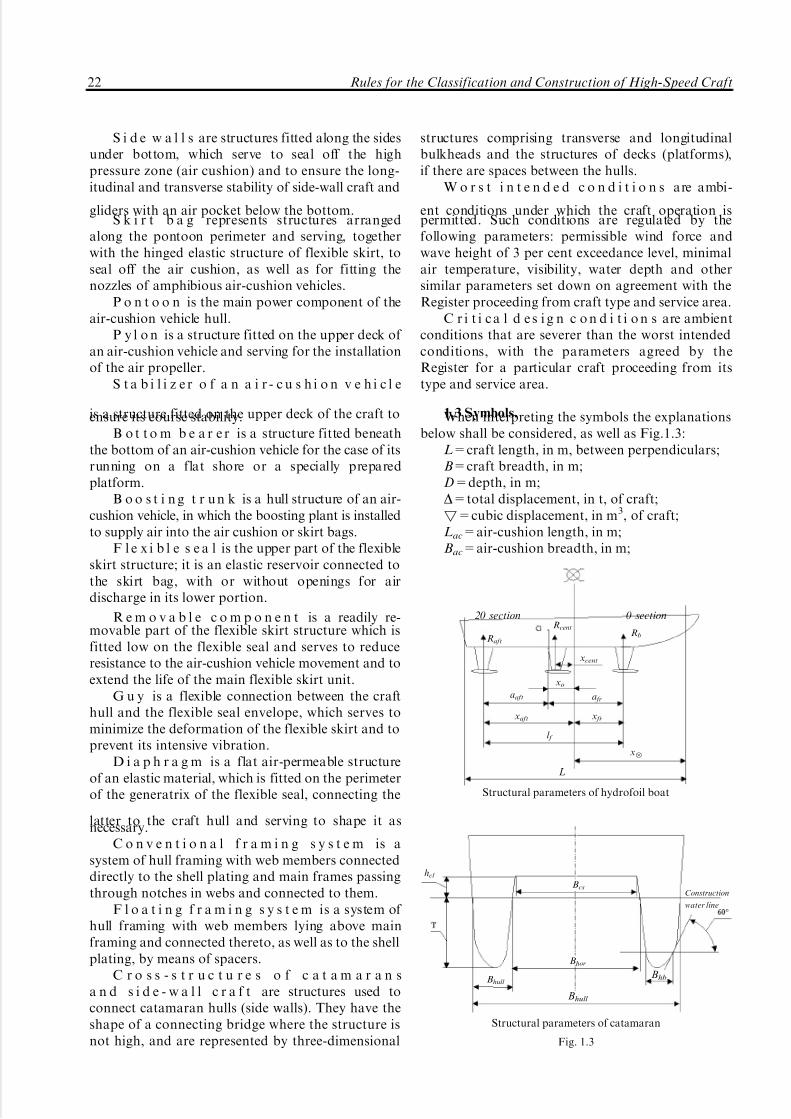
1.3 Symbols.When interpreting the symbols the explanationsbelow shall be considered, as well as Fig.1.3:
L=craft length, in m, between perpendiculars;B=craft breadth, in m;D=depth, in m;D=total displacement, in t, of craft;!=cubic displacement, in m3, of craft;Lac=air-cushion length, in m;Bac=air-cushion breadth, in m;
Construction
water line
Raft
aaft a fr
x frxaft
l f
x6
Rcent
xcent
xo
Rb
hcl
Bcs
Bhor
Bhull
Bhull
Bhb
20 section 0 section
L
Structural parameters of hydrofoil boat
Structural parameters of catamaran
Fig. 1.3
22 Rules for the Classification and Construction of High-Speed Craft

5/12/2018 High Speed Craft Rusa - slidepdf.com
http://slidepdf.com/reader/full/high-speed-craft-rusa 24/167
S ac=air-cushion area, in m2;Bsw=side-wall breadth, in m;H sw=side-wall height, in m;H fs=flexible-skirt height, in m;
a=waterline area coefficient of fullness;hcl =vertical clearance, in m (for high-speed
catamarans and side-wall craft, this is the distancebetween the undisturbed surface of liquid and theconnecting bridge at midlength section, and forhydrofoil boats it is the distance between theundisturbed surface of liquid and the keel line);
hcl =hcl /h3% = relative clearance of craft;h3%=wave height of 3 per cent exceedance level,
in m, for which provision is made in the craft designfor the relevant motion pattern and which shall beadopted on the basis of the scale currently used in the
Russian Federation;h=h3%/3H! = relative wave height;l f =distance, in m, between the front and aft foil
installations;a fr=distance, in m, between the front foil
installation and the mass centre of the craft;aaft=distance, in m, between the aft foil installa-
tion and the mass centre of the craft;x = distance, in m, between the craft cross
section under consideration and the transom;xmid = abscissa, in m, of the craft cross section
under consideration, as measured from the midlengthsection;
x g = distance, in m, between the transom and themass centre of the craft;
x g = xg/L = relative distance, in m, between thetransom and the mass centre of the craft;
x fr, xcent, xaft = distance, in m, between themidlength section and the front, central and aft foilinstallations accordingly;
x6=distance, in m, between the midlengthsection and the forward perpendicular;
l fr=distance, in m, between the front foilinstallation and the mass centre of the craft;
xo=distance, in m, between the mass centre of
the craft and the midlength section;mx=craft mass per metre;rx and r y=inertia radii, in m, of the craft hull
mass with regard to the longitudinal and transverseaxes accordingly which pass through the mass centreof the craft;
I x and I y=inertia moments, in kg/m2, of the craft
hull mass with regard to the longitudinal andtransverse axes accordingly which pass through themass centre of the craft;
I 6 = inertia moment, in m4, of hull cross sectionat midlength;
W =moment of resistance of hull cross section;V =craft speed, in knots, in the motion pattern under
consideration with the specified intensity of the sea h3%;
V hb=craft speed, in knots, in the hull-borne mode(for air-cushion vehicles, V hb will not generally exceed3 knots proceeding from the flexible skirt strength);
V lift = speed at which a hydrofoil boat reaches
the condition when it is borne by the front hydrofoilinstallation, to be determined by the maximumresistance value;
FrD=0,514V /H g!1/3=Froude number by dis-placement;
FrL=0,514V/H gL=Froude number by length;n = yÈ /g = relative acceleration (overload);n g = relative acceleration at the centre of mass of
the craft when it moves as a solid body; yÈ = vertical acceleration, in m/s2, in the hull
sections;C y
max=maximum lifting force coefficient of foil
component section, to be determined by experiment;R fr, Rcent and Raft = forces, in t, taken by thefront, central and aft foil installation respectively;
P fr.st.w., Pcent.st.w. and Paft.st.w. = forces, in t, takenby the front, central and aft foil installationrespectively when moving on still water;
C fr, C cent and C aft = lifting force buildupcoefficient for the front, central and aft foil installationrespectively on the seas as compared to still water;
Pdes = design force, in t, acting upon the foilinstallation as a whole and equal to, respectively:
P frmax for the front foil installation, in t;
Pcentmax for the central foil installation, in t;
Paftmax for the aft foil installation, in t;Pcomp=design force, in t, acting upon the foil
installation component in question;S f = horizontal-plane projection area, in m2, of
the submerged part of foil installation lifting surface;S comp = horizontal-plane projection area, in m2,
of the submerged part of the foil installationcomponent in question;
S str = projected area, in m2, of submerged partsof stanchions and inclined components of foilinstallation on the centre plane;
b= dead-rise angle, in deg, of the inclined
component of foil installation; g = 9,81 m/s2 = gravity acceleration;r=1 t/m3 (kN´s2/m4)= water density;g=10 kN/m3 = seawater density;M sag, M hog=design bending moments in hull
cross sections during hull sagging and hoggingaccordingly;
M st.w.sag , M st.w.
trans=longitudinal and transverse bend-ing moment, in tm, accordingly, on still water in themotion pattern under consideration;
M wsag, M w
hog, M wtrans, M w
tw=wave component, intm, of bending moment for the case of longitudinal(sagging and hogging) and transverse bendingaccordingly, as well as for hull twisting, in themotion pattern under consideration;
Part II. Hull Structure and Strength 23

5/12/2018 High Speed Craft Rusa - slidepdf.com
http://slidepdf.com/reader/full/high-speed-craft-rusa 25/167
M d sag, M d
hog, M d trans, M d
tw=dynamic component, intm, of bending moment for the case of longitudinal(sagging and hogging) and transverse bending,accordingly, as well as for hull twisting, in the
motion pattern under consideration;M des
sag, M deshog, M des
trans, M destw =design values, in tm, of
bending moment for the case of longitudinal (saggingand hogging) and transverse bending, as well as forhull twisting, in the motion pattern under considera-tion;
M st.w6 , M w
6, M d 6, M des
6=relevant bending mo-ment values, in tm, in the midlength section;
M cp=centre-plane bending moment value, in tm,for the case of transverse bending of hull of a side-wall craft;
M ult = ultimate bending moment, in tm;Q
st.w.
sag
,Q
st.w.
hog
,Q
st.w.
trans
=shearing force, in t, for thecase of longitudinal (sagging and hogging) andtransverse hull bending, accordingly, in the motionpattern in question;
Q wsag, Q w
hog, Q wtrans=wave component, in t, of
shearing force for the case of longitudinal (saggingand hogging) and transverse hull bending, accord-ingly, in the motion pattern in question;
Q d sag, Q d
hog, Q d trans=dynamic component, in t, of
shearing force for the case of longitudinal (saggingand hogging) and transverse hull bending, accord-ingly, in the motion pattern in question;
Q dessag, Q des
hog, Q destrans=design values, in t, of shearing
force for the case of longitudinal (sagging andhogging) and transverse hull bending, accordingly,in the motion pattern in question;
s0=dangerous normal stresses, in kPa;R p02=yield strength, in kPa, of aluminum alloy;ReH =upper yield stress of steels, in MPa;Rm=ultimate strength of material, in kPa;s per=permissible normal stresses, in kPa;scr=critical normal stresses, in kPa;se=Euler buckling stresses, in kPa;tn=shear yield strength of material, in kPa;t0=dangerous normal stresses, in kPa;
tcr=critical normal stresses, in kPa;t per=permissible normal stresses, in kPa;T = maximum strain of flexible skirt material,
in kN/m;Rb=breaking strengh of flexible skirt material,
in kN/m;xt=distance, in m, between the point under
consideration (hull section under consideration) andtransom;
B6=hull breadth, in m, at midlength over thebilge;
Btr=transom breadth (distance between chinelines in way of aft perpendicular), in m;
B3=hull breadth over the bilge in way of 3dsection;
ba=dead-rise angle, in deg, for the hull section inquestion;
b3= dead-rise angle, in deg, for 3d hull section;b:=dead-rise angle, in deg, for midlength
section;btr= dead-rise angle, in deg, in way of transom;bav=(b:+btr)/2=average dead-rise angle, in
deg;Bhull =hull breadth, in m, at midlength on
construction waterline level;Bhor=horizontal clearance = inter-hull distance,
in m, in the midlength section, as measured on theconstruction waterline plane;
Bhb=hull breadth, in m, at midlength, asmeasured over the waterline corresponding to hullimmersion up to the bilge level;
j =section number;Bcs=cross-structure breadth (inter-hull distanceon the cross-structure level), in m;
S o = area, in m2, supported by a hull element(load removal area); for plates, the supported areashall be adopted equal to the product of the stiffenerspan (spacing) and the value corresponding to thegreater side length of the plate or to three times thespacing (whichever is less);
T = craft draught, in m, in still water;xmid = abscissa, in m, of the point under
consideration, as counted from the midlength section(a negative value where the point lies aft of
midsection); y = distance, in m, between the hull point under
consideration or its longitudinal section, and thecentre plane;
Z i = distance, in m, between the point underconsideration and the design waterline level;
b(x) = hull breadth, in m, in the cross sectionunder consideration with the x abscissa.
1.4 Scope of technical supervision.
To be submitted to the Register is technicaldocumentation in the number stipulated in Section 5,Part I "Classification" of Rules for the Classification
and Construction of Sea-Going Ships. Besides,structural drawings and strength analyses shall besubmitted for hydrofoil installations, flexible skirtsand hull strengthening of these devices, as well as thestrength analysis of the pilot (experimental) project,which shall be made on the basis of sea trials results.
1.5 Materials of hull and special devices.
Hull materials of high-speed craft and foilinstallations of hydrofoil boats shall be in accordancewith the requirements of Part XIII "Materials" of Rules for the Classification and Construction of Sea-Going Ships.
The Rules provide for aluminum-magnesiumalloys to be used for hull structures, for stainlesssteels and titanic alloys to be used for foil installa-
24 Rules for the Classification and Construction of High-Speed Craft

5/12/2018 High Speed Craft Rusa - slidepdf.com
http://slidepdf.com/reader/full/high-speed-craft-rusa 26/167
tions, and for rubber cloth or other polymermaterials up to 6 mm thick to be used for flexibleskirt. For auxiliary (take-off) components of foilinstallations, which ensure passing to the foil-borne
mode, aluminum-magnesium alloys may be used.On agreement with the Register, non-metallic
materials may be used for hull structures.Material grades for flexible skirts shall be chosen
on the basis of strength analysshall be carried out inaccordance with 5.7 of Part XIV "Welding" of Rulesfor the Classification and Construction of Sea-GoingShips, as well as of laboratory tests of static strength of specimens produced by the procedure and underconditions used by the manufacturer, and they shallbe certified by the Register.
1.6 Welding.
1.6.1 The welding of structures in dynamicallysupported craft shall be carried out in accordance withthe requirements of Part XIV "Welding" of Rules forthe Classification and Construction of Sea-GoingShips. On agreement with the Register, resistance spotwelding and resistance seam welding of aluminumalloys may be permitted for supporting structureswhere the components are up to 3 mm thick.
1.6.2 Stainless steel shall be welded in accordancewith the requirements of Part XIV "Welding" of Rules for the Classification and Construction of Sea-Going Ships, and with the standards approved by theRegister.
The technical documentation submitted for theRegister approval shall stipulate:
cutting procedures and conditions for compo-nents, as well as edge preparation for welding;
bending and straightening procedures and con-ditions for components (hot or cold);
straightening procedures and conditions forwelded structures;
welding conditions and procedures, types of welded joints;
surface finishing procedures and norms forwelded joints;
welding consumables, their properties, storageand application conditions;
permissible level of weld quality;removal and repairing procedures for weld
lengths with impermissible defects;types of weld tests;required mechanical properties of welds;types of weld heat treatment and its indispensa-
bility before or after welding.Welding consumables, such as electrodes, weld-
ing wire, flux and shielding gases shall be certified bythe Register.
The chemical composition of deposited metal andthe mechanical properties of welds shall comply withstandards approved by the Register.
The application of welding procedures notstipulated in the present Rules or standards to newmaterials is subject to the Register approval.
1.6.3 Welds in foil installations shall undergo
non-destructive testing to the extent agreed with theRegister.
2 HULL DESIGN PRINCIPLES
2.1 General.
2.1.1 This Part of the present Rules covers hullstructures and special devices produced by welding(electric arc, gas-shielded, resistance welding, etc.),riveting, glued riveting and pressure-contact glued
welding.2.1.2 When designing the hull structures of high-speed craft, requirements shall be considered for theirstrength and life providing a minimal weight andoptimal construction procedure. These requirementsshall be complied with during all stages of the craftdesign.
2.1.3 For hull-structural design, provision shallbe made for all-pressed and glued-welded panels tobe used as widely as practicable, and the components,units and sections forming the hull shall be standar-dized and typified. As far as practicable, panels(structural blanks) having the largest dimensions
shall be used to reduce the number of welded and, inparticular, riveted joints in hull structures.
Generally, welded hull structures shall be stipu-lated in the design. The main welding procedure shallbe fusion welding. Riveted joints and spot welds maybe used where welding is not feasible or inexpedientdue to technical or structural reasons, especially when
joining non-weldable or limited-weldable materials,or those which may involve impermissible structuraldeformations during welding. In welded structures,riveted joints may be applied as barriers (stoppers)for limiting crack propagation. In structures below
the waterline, riveting may be applied subject to theRegister agreement (proceeding form integrity ensur-ing conditions).
2.1.4 With all-pressed and glued-welded panels,the floating (longitudinal or transverse) framingsystem shall be applied to get the utmost of thestructural and technical advantages afforded by usingthe panels. In areas to which considerable concen-trated forces are applied, the main framing shall befitted directly on the shell plating or be aligned withpanel stiffeners.
2.1.5 Within the hull, transition from the floatingto the conventional framing system shall be effectedin way of main framing (stringers, web frames,bulkheads, platforms, etc.).
Part II. Hull Structure and Strength 25

5/12/2018 High Speed Craft Rusa - slidepdf.com
http://slidepdf.com/reader/full/high-speed-craft-rusa 27/167
2.1.6 Along the length and breadth of the hull, asmooth transition of sectional dimensions and platethickness may be effected in conjunction with thevariation of forces due to the total longitudinal and
transverse bending of the hull, which shall besubstantiated by a relevant strength analysis.
2.1.7 No abrupt variation of plate thickness andsection depth is permitted. The difference of buttedplates shall not exceed 40 per cent by thickness(except specially strengthened areas, in way of opening angles, for instance).
Provision for a smooth section depth variationshall generally be made at intersections with webframing members (stringers, frames, bulkheads, etc.).
2.1.8 All rectangular hull openings and those of other shapes shall have their corners rounded.
For longitudinal hull members, the angle round-ing radii shall be at least as follows (whichever isgreater):
5 member web thicknesses;0,15 of the length of the shorter opening side;30 mm.2.1.9 For bearing structures, the spot and seam
welding may be permitted for components up to3 mm thick.
2.1.10 For bearing structures with the thicknessS 55,0 mm, indirect deep penetration welding of buttwelds may be permitted. Indirect welding shall not beapplied in areas of intensive vibration.
2.1.11 During hull structures manufacture it shallbe possible to apply the maximum number of mechanized welding procedures and to make themajority of welds in the downhand position.
2.1.12 The Rules consider standard joints of structural components. When designing new projects,the standard structural components recommendedmay be optimized and corrected proceeding from therequirements for the particular structure.
2.1.13 Where main hull structures include com-ponents essentially different from the standard ones,the former shall undergo full-scale testing in accor-
dance with a program approved by the Register.2.1.14 For decks, bottom, sides, longitudinal
bulkheads, skirt bags and solid superstructures, thelongitudinal (conventional or floating) framing sys-tem shall generally be applied. For the hull, mixedframing system is permissible, as well as transverseframing system for the superstructure.
For additional framing members, a transitionfrom one system to the other is permitted.
In areas to which considerable concentratedforces are applied, web framing members shall beattached directly to the shell plating.
2.1.15 Hull member scantlings shall be deter-mined on the basis of the overall and local strengthanalysis. The scantlings to be determined by the
overall strength analysis for the midlength hullsection shall be observed within 0,4L (0,2L forwardand aft of midlength) of the midlength region.
2.1.16 Ensuring the continuity of longitudinal
bulkheads is mandatory. Where longitudinal mem-bers terminate, provision shall be made to ensuresmooth variation of their scantlings together withother measures aimed at reducing stress concentra-tion. Where the continuity of members is impaired,including an abrupt change of their direction, arelevant structural solution shall be provided.
2.1.17 Not more than two main longitudinals of decks, sides and bottom (carlings and stringers),symmetrical to the centreline plane, shall terminate inthe same hull cross section.
2.1.18 Unless expressly stipulated otherwise in
the Rules, provision shall be made for the depth of main longitudinal members of decks, sides andbottom (centreline girder, side and bottom stringersand carlings) to be recluced over a length 51,5 of themember depth where these members terminate.
Longitudinal member ends shall be led to thenearest transverse member and connected thereto.
2.1.19 In areas of intensive vibration, as well as intanks where penetrated by girders or where bracketsrest upon tight structures, provision shall be made forstiffeners, shelves or other structural elements toprevent hard spot formation in welded structures.
2.1.20 Openings shall be avoided in strength
deck, skirt bag, carlings, centreline girder andstringers. If openings are made in the abovemembers, the latter shall be strengthened. The designof strengthening shall allow for lost area compensa-tion together with reducing the stress concentration.The edges of the openings shall be smooth.
2.1.21 The openings for air supply in the deckplating and cross-structure of side-wall craft shall bestrengthened with vertical fillets along their contour,and the plating proper shall be thickened.
2.1.22 Rectangular openings in deck, sides andlongitudinal bulkheads shall be arranged with their
greater side along the ship's length.For small rectangular openings (where the open-
ing breadth or the total breadth of openings in aparticular ship cross-section would not exceed half the ship breadth), the angle rounding radius shall notbe less than:
0,15 of the lesser side of the opening;10 times the shell plating thickness;50 mm.2.1.23 The plate edges shall lie not nearer than
1/3 of the opening length to the opening edge, but inany case the distance shall not be less than 2r where r
is the rounding radius of opening.
26 Rules for the Classification and Construction of High-Speed Craft

5/12/2018 High Speed Craft Rusa - slidepdf.com
http://slidepdf.com/reader/full/high-speed-craft-rusa 28/167
2.2 Girder attachment.
2.2.1 For longitudinals, pressed symmetrical bulband tee-sections shall be used, or pressed panels withsymmetrical ribs of bulb or tee-cross-sections.
In structures incorporating riveted, glued-rivetedor glued-welded joints, pressed or bent sections of other shapes may be used (angle bulbs, angles, Z-sections).
For bottom, side and deck longitudinals (includ-ing superstructures and deckhouses), skirt bag andside walls, unsymmetrical bulb sections and anglesmay be used. With the floating framing system, thetorsion rigidity of unsymmetrical section girders shallbe ensured.
It is recommended that web framing members(web frames, floors, side wall brackets, carlings, web
beams, stringers, etc.) are made of pressed sectionsand panels. Welded sections may also be used.With the conventional framing system, tee-
sections shall be mainly used for web members, andwith the floating system, I-sections shall be used.
2.2.2 Framing members shall be butt-welded. Nolap welding is permitted.
2.2.3 In welded-section butts, the distance be-tween flange butts and web butts shall be adopted notless than half the girder depth.
2.2.4 The web beam depth variation shall takeplace in way of rigid members (bulkheads, stringers,web frames, beams, etc.) where brackets shall be
fitted (Fig. 2.2.4-1).
Where the transitional depth 5(H 7h)5l (Fig. 2.2.4-2), the sectional depth between rigidmembers may be varied.
2.2.5 The dimensions of brackets connecting theframes in welded structures shall be chosen on the
basis of directions contained in the figures of thepresent Part. The bracket thickness shall be chosenequal to the minimal section web thickness of theframe(s) connected (fixed). Deviation from recom-
mended thickness shall be well grounded in each case.Where necessary, free bracket edges shall be
strengthened with face plates which shall be 1 mmthicker than the brackets. Forward-bent flanges mayalso be used.
The free ends of bracket face plates or flangesshall be snipped on a length equal to 1,5 the bracketface plate (flange) breadth. The blunting length shallbe adopted not greater than three times the face plate(flange) thickness. The distance between the faceplate end and the blunted bracket shall not be lessthan two times the bracket thickness. In the case of
highly stressed structures working under alternatingloads, the above blunted edges shall be rounded to aradius (Fig. 2.2.5).
2.2.6 Brackets, section webs and other permeableplate structures shall be cut in accordance withFig. 2.2.6.
Fig. 2.2.4-1
l 55 (H 7h)Fig. 2.2.4-2
Edging mill
Fig. 2.2.5
or
Fig. 2.2.6
N o t e . In non-essential structures, an out with a side size a=ris permitted instead of a cut on the radius r for weld passage.
Part II. Hull Structure and Strength 27

5/12/2018 High Speed Craft Rusa - slidepdf.com
http://slidepdf.com/reader/full/high-speed-craft-rusa 29/167
2.2.7 Where girders terminate, the flanges andwebs of the latter shall be snipped over a length equalto 1,5 flange breadths or 1,5 web depth accordingly,with an unbevelled edge area (blunting) to be left on
the free end, equal to three times the flange thicknessfor flanges and to three times the web thickness atleast for webs. Provision shall be made for leaving adistance between the flange end and the girder webend of two times the web thickness at least or 15 mm,whichever is greater (Fig. 2.2.7).
2.2.8 The edges of brackets, section webs andconnecting plates shall be boxed and shall have nocraters.
2.2.9 Where the floating or conventional framingsystem is applied, the main longitudinal hull members
shall be continuous between transverse bulkheads. If the longitudinal and transverse girders of conven-tional framing have equal depth, the longitudinalgirders may be intercostal in way of floors.
The vertical stiffeners of transverse and long-itudinal bulkheads shall be continuous between thebottom and deck, as well as between decks. Stiffenersmay be terminated on the additional shelf.
2.2.10 Main longitudinal hull members shall beconnected to transverse watertight bulkheads andfloors in conformity with Figs. 2.2.10-1 and 2.2.10-2.Web girders shall be connected to plate edges inconformity with Fig. 2.2.10-3.
2.2.11 With the floating framing system, long-itudinal frames, except the centreline girder
(see 2.2.9), whose depth is equal to that of transverseframes shall be intercostal frames. Connectingassemblies shall be in compliance with Fig. 2.2.11-1.
Assemblies connecting main longitudinal framesto transverse frames of lesser depth shall be inconformity with Figs. 2.2.11-2 and 2.2.11-3. Wherethe difference in the depth of a longitudinal memberis small as compared to that of a cross girder, theconnecting assembly may include brackets (seeFig. 2.2.11-4) or restraints (Fig. 2.2.11-5).
a)
b)
Fig. 2.2.7
Continuous weld
Fig. 2.2.10-1
Fig. 2.2.10-2
Continuous weld
A-A
Fig. 2.2.10-3
28 Rules for the Classification and Construction of High-Speed Craft

5/12/2018 High Speed Craft Rusa - slidepdf.com
http://slidepdf.com/reader/full/high-speed-craft-rusa 30/167
2.2.12 With the floating framing system, floorsshall be connected to the centre girder in accordancewith Fig. 2.2.12-1 or 2.2.12-2 (flat or raised bottom)proceeding from their relative depth.
2.2.13 With the conventional framing system,web frames shall be connected to floors in accordancewith Fig. 2.2.13-1, and with the floating framing
system, in accordance with Fig. 2.2.13-2. Thedistance between the member web edge and theopening therein for longitudinals shall not be lessthan 100 mm. With a small spacing of panel stiffeners(below 200 mm), this distance may be reduced (and itis recommended that all sections between edges andopenings are equal).
A
Fig. 2.2.11-11-floor, 2-bottom stringer, 3-bottom longitudinal,
4-connecting plate, 5-horizontal bracket, 6-face plate expansion
Frame
Tight stringer
Fig. 2.2.11-2
Stringer
Frame
A
Fig. 2.2.11-3
Frame
Stringer
Fig. 2.2.11-4
Frame
Fig. 2.2.11-5
Tight centre girder
Frame
b)
Fig. 2.2.12-1
Part II. Hull Structure and Strength 29

5/12/2018 High Speed Craft Rusa - slidepdf.com
http://slidepdf.com/reader/full/high-speed-craft-rusa 31/167
With floor depth below 200 mm, the connectingassemblies of web frames shall be in accordance withFig. 2.2.13-3 where conventional framing system isapplied.
The connecting assemblies of continuous webframes and the web beams of decks and platforms at
penetrations through the latter shall be in conformitywith Fig. 2.2.13-4, while the connecting assemblies of web frames that are intercostal in way of decks andplatforms, and the web beams of decks and platformsshall be in conformity with Fig. 2.2.13-5.
Centre girder
Floor
b)
Fig. 2.2.12-2
Frame
Floor
Frame
Floor
Fig. 2.2.13-1
Fig. 2.2.13-2
Floor
Frame
Frame
Deck
(platform)
Beam
Fig. 2.2.13-3
Fig. 2.2.13-4
Frame
Deck
(platform)
Beam
Fig. 2.2.13-5
30 Rules for the Classification and Construction of High-Speed Craft

5/12/2018 High Speed Craft Rusa - slidepdf.com
http://slidepdf.com/reader/full/high-speed-craft-rusa 32/167
The connecting assemblies of web frames and theweb beams of superstructure deck shall be inconformity with Fig. 2.2.13-6.
2.2.14 For assemblies by which the penetration of longitudinal girders through non-tight structures isensured, either clear openings (Fig. 2.2.14-1) oropenings where the girder web is welded directly tothe opening edge by double-side welding (Fig. 2.2.14-2)shall be used proceeding from the girder height.
2.2.15 For non-tight structures, welding of effective flanges of girders to opening edges is notpermitted. The angles of openings shall be rounded to
a radius not less than three times the wall thickness of the structure in which the opening is made, or10 mm, whichever is greater.
2.2.16 In web members, the separation of any
opening edge from the edge of the opening for girderpenetration shall equal the girder height at least,unless a greater value is specified proceeding from thestrength conditions.
2.2.17 With the floating framing system, noopenings in centre girder or floors are permitted.
In carlings and stringers, openings for frames arepermitted, which shall not exceed 1/2 the memberweb height in the section under consideration.
Where this is not feasible, the web strengthdeterioration shall be compensated by its thickening,fitting of restraints or in another way.
2.2.18 With the conventional framing system,non-tight structures with clear openings and twobrackets (fitted on each side of the supportingstructure) measuring not less than 2h (h being girdersection height) shall be applied where the girderheight is below 80 mm. When the girder height equalsor exceeds 80 mm or when the girders are intercostalin way of web girders and are welded to the webs of the latter, the brackets size shall not be less than 1,5h.
Where the distance between the effective flangeof a longitudinal and the girder flange of web framingis less than:
2,0h with the girder height <80 mm,
or 1,5h with the girder height 580 mm,the brackets shall be welded to the effective
flange of web framing girder.When applying both framing systems, continuous
girders may be connected to web framing girders of bottom, sides and decks by means of brackets fittedin staggered rows. Where h<80 mm, brackets may befitted in accordance with Fig. 2.2.21.
2.2.19 The connecting assemblies between long-itudinals and transverse tight bulkheads or floors shallbe executed in conformity with Figs. 2.2.19-1(variant 1) or 2.2.19-2, and where pressed panels are
used to connect the beams of continuous panels, inconformity with Figs. 2.2.19-3 and 2.2.19-4 (variant 1).
The possibility of applying variants 2 of connect-ing assemblies (Figs. 2.2.19-1 and 2.2.19-4) shall besubstantiated by the assembly service life analysis.
2.2.20 If pressed panels are used in structures, themain longitudinal hull members shall be welded tothe flanges of longitudinals, and if welded panels areused, they shall be welded directly to the plating.
2.2.21 With the floating framing system, con-necting plates (brackets) shall be fitted in way of crossover assemblies between the main members(panel sections) and intersecting members (webframing) of the hull (including the bilge area andthe intersections of the side with platforms and deck)
Frame
Deck (platform)
Beam
Fig. 2.2.13-6
h<80 mmFig. 2.2.14-1
h580 mmFig. 2.2.14-2
Part II. Hull Structure and Strength 31

5/12/2018 High Speed Craft Rusa - slidepdf.com
http://slidepdf.com/reader/full/high-speed-craft-rusa 33/167
on the planes of the web plates of the intersectingmembers. Where the panel section height exceeds70 mm, the connecting plate edges shall be roundedon a radius (Fig. 2.2.11-1).
At girder intersections, the effective flanges of panel sections and web members shall be connectedby welding with brackets fitted in staggered rows(Fig. 2.2.21). If the effective flange thickness of panel
sections is less than 50 mm, brackets alone wouldsuffice.
2.2.22 When pressed panels are used, theconnecting assemblies between framing membersand adjacent structures shall be in conformity withFigs. 2.2.22-1 and 2.2.22-2, and the connectingassembly between deck girders and the longitudinalbulkhead girders shall be in conformity withFig. 2.2.22-3.
Variant 1 Variant 2
h<80 mm
Fig. 2.2.19-1
h580 mm
Fig. 2.2.19-2
B
BB-B
Fig. 2.2.19-3
Variant 1 Variant 2
B B
B B
B-B
Fig. 2.2.19-4
Fig. 2.2.21
Plating(pressed panel)
Stringer(pressed panel)
Stringer(pressed panel)
Plating(pressed panel)
Plating(glued-welded panel)
Deck(pressed panel)
Deck(pressed panel)
Beam
Longitudinal bulkhead (pressed panel)
Fig. 2.2.22-1
Fig. 2.2.22-2
Fig. 2.2.22-3
32 Rules for the Classification and Construction of High-Speed Craft

5/12/2018 High Speed Craft Rusa - slidepdf.com
http://slidepdf.com/reader/full/high-speed-craft-rusa 34/167
2.3 Components of welded structures.
2.3.1 The free edges of girder webs and flanges,brackets, etc. shall undergo mechanical treatmentand shall not be rough. When brackets, knees,
stiffeners, etc. are welded to the effective flanges of girders being stiffened, they shall not reach theeffective flange edge by a margin of 15 mm or doublethickness, whichever is greater. The flanges of kneesand brackets fitted to stiffen web girders (long-itudinal bed-plate girders included) shall be snipped.
2.3.2 The right angles of brackets with which theconnecting assemblies of girders are stiffened shall beexecuted so that the cut edge is removed from thecontour of the opening for girder passage throughweb member by 15 mm at least (Fig. 2.3.2).
2.3.3 Welding of bed-plate girder flanges tobottom plating or to transverse bulkhead plating is
not permitted. In the above areas, the flanges shall besnipped.
2.4 Weld location.
2.4.1 Welds shall be located in the mostunstressed sections of the structure and shall, as faras practicable, be parallel to forces applied and beremoved to the maximum extent possible from areasof abrupt change of member scantlings, openingdiameter, and from other stress concentrators.
2.4.2 Clusters of welds, their intersection at rightangles and location of parallel butt welds or filletwelds (tee welds) and butt welds in close proximity
shall be avoided.Butt welds in plate structures shall be removed
from each other by 100 mm at least on the lengthwithin sections and assemblies, if made earlier thanthe welds with which they intersect.
In case of construction welds, the minimaldistance between butt welds and fillet welds parallelthereto shall not be less than 100 mm or 10 times theplate thickness, whichever is greater. Where theabove welds are shorter than 2 m, they shall beremoved from each other by 50 mm at least.
The angle between two butt welds shall not beless than 458 (Fig. 2.4.2).
2.4.3 It is recommended to arrange the effectiveflange butts of web framing members (stringers,
calrings, floors, beams) at an angle of 458 to thelongitudinal axis of the member.
2.5 Welds.
2.5.1 Butt welds.
2.5.1.1 It is recommended that welds in support-ing structures having a thickness of 4 mm or aboveshall be made with edge preparation.
In components up to 10 mm in thickness, weldsare permitted without edge preparation on conditionautomatic indirect welding is used to ensure weld-root formation.
2.5.1.2 When plates of different thickness areabutted, the difference in their thickness is generallynot to exceed 40 per cent of the thicker platethickness. This does not apply to thickened platesfitted under hawse pipes, pylons, bottom supports,etc. The thicker plate edge shall be bevelled until it
r ea ch es t he t hi ck ne ss o f t he t hi nn er p la te(Fig. 2.5.1.2).
2.5.1.3 Butt joints in girders shall be welded bydirect welding using runoff blocks. Strapped lap
joints are not permitted. In hard-to-reach areas,indirect welding on removable backing is permitted(also using runoff blocks).
2.5.2 Tee joints.
2.5.2.1 The leg length of tee welds in hull structureswill be determined on the basis of strength analysis, butit shall not be less than stated in Table 2.5.2.1.
2.5.2.2 Welds in tee joints made by direct weldingwith edge preparation shall be used where thethickness of plates (components) is 4 mm or above in:
Fig. 2.3.2
Side
Fig. 2.4.2
Fig. 2.5.1.2
Part II. Hull Structure and Strength 33

5/12/2018 High Speed Craft Rusa - slidepdf.com
http://slidepdf.com/reader/full/high-speed-craft-rusa 35/167
connecting assemblies of main hull girders,namely, web frames and stringers, floors and webframes, stringers and bulkheads, etc., as well as inbracket joints, flange joints and girder stiffeners;
structures and stiffeners coming under dynamicand vibration loads (pylon footings, machineryseatings, bottom supports, etc.).
2.5.2.3 Continuous welds in tee joints made by
direct welding without edge preparation may be usedin connecting assemblies of web members (stringers,carlings, web frames, etc.) and shell or plating exceptfor members coming under alternating loads.
2.5.2.4 Welds not less than 50 mm in length madeon the opposite side of the wall of the componentbeing welded by indirect continuous welding in tee
joints arranged 150Ð200 mm from each other(Fig. 2.5.2.4) are permitted for welding longitudinalsto shell plating and to deck and platform plating, forwelding bulkhead stiffeners to bulkhead plating andfor welding flanges to welded section walls, etc.,except for areas of longitudinals and web framing
intersection and intensive vibration areas, only whenthe stress level is low in the structure.
When joints of this kind are used, the memberends shall be boxed on a length not less than 1,5 of the section height.
2.5.2.5 Intermittent welds made by direct weldingwith bead overlapping on the opposite side by 20 mmat least, the beads being 150 Ð 200 mm long(Fig. 2.5.2.5), are permitted in tee joints of smallthickness (less than 3 mm) outside of intensivevibration areas. In any case, girders shall be weldedto shell plating and plating in way of supports andgirder ends by using continuous direct welding. Theweld length to each side of the support (girder end)shall be equal at least 1,5 times the bracket height or
that of the higher girder being connected, whicheveris greater.
2.6 All-pressed panel joints.
2.6.1 All-pressed panels shall be generally con-nected by welding.
For panels less than 3,0 mm in thickness, rivetingor glueing and riveting is recommended.
In panel connections, the seams on the surface
and edges shall be made on the same plane.2.6.2 It is recommended that the panel length
shall be adopted equal to the length of one or severalcompartments.
Panels shall be used whose edges have asymmetrical bulb or tee section.
2.6.3 For panels with unsymmetrical edges, thetorsional rigidity of stiffeners shall be increased, wherenecessary, by the fitting of brackets proceeding fromthe stiffener web thickness in accordance with Fig.2.6.3-1 (the thickness being not less than 3 mm) or withFig. 2.6.3-2 (the thickness being less than 3 mm).
2.6.4 The butt joints of panels, except low-loadedstructures in which the section height is not greaterthan 90 mm, shall be strengthened with stiffeners(Figs. 2.6.4-1, 2.6.4-2a, 2.6.4-2b).
The cross-sectional area of stiffeners shall not beless than 0,5 of the cross-sectional area of paneledges. A deviation from this requirement or fromrecommendations for executing the connecting as-semblies (Figs. 2.6.4-1, 2.6.4-2a, 2.6.4-2b) is onlypermissible where it is substantiated by test resultsobtained on panel connecting assemblies and bycalculations.
Where necessary, tee sections shall be used toincrease the plane bend resistance of connectingassemblies.
Welded platethickness
(web/flange), in mm
3
3715
4
4715
6
6
6
8715
8
8715
8
15
10
10
10
15
15
15
Minimal leg length, inmm
3+1 3+1 4+1 5+1 5+1 6+1 6+1 7+1 7+1
T a b l e 2.5.2.1
Fig. 2.5.2.4
Fig. 2.5.2.5
34 Rules for the Classification and Construction of High-Speed Craft

5/12/2018 High Speed Craft Rusa - slidepdf.com
http://slidepdf.com/reader/full/high-speed-craft-rusa 36/167
2.6.5 Solid panels shall be connected to water-tight bulkheads, floors and stringers in accordancewith Figs. 2.2.19-3 and 2.2.19-4.
Combined connecting assemblies inside blocks orbetween sections of pressed panels shall be executedin conformity with Figs. 2.6.5-1, 2.6.5-2 and 2.2.22-1,2.2.22-2, 2.2.22-3, and similar assemblies between
pressed panel blocks shall be executed in conformitywith Fig. 2.6.5-3. The cross-sectional area of abracket fitted above the panel joint shall not be lessthan 0,7 of the edge cross-sectional area. A deviationfrom these recommendations is only possible if
h>80h<80
Fig. 2.6.3-1 Fig. 2.6.3-2
welding
Minimal valueon conditionof stiffener welding
b<40 mm
welding
Fig. 2.6.4-1
b)
Minimal value on
condition of
stiffener welding
b>40 mm
b>20 mm
Fig. 2.6.4-2
B
B-BB See also B-B in Fig. 2.2.19.3
Fig. 2.6.5-1
See B-B in Fig. 2.6.5-1
Fig. 2.6.5-2
B
A A
B
See B-B- in Fig.2.6.5-1
Fig. 2.6.5-3
Part II. Hull Structure and Strength 35

5/12/2018 High Speed Craft Rusa - slidepdf.com
http://slidepdf.com/reader/full/high-speed-craft-rusa 37/167
substantiated by assembly test results and calcula-tions.
Where the bracket cannot be abutted or weldedto the shelf, this shall be substantiated by assembly
durability analysis.2.6.6 When connecting structural components
composed of all-pressed panels, one shall also beguided by 2.2.20, 2.2.22, 2.12.5.
2.7 Riveted and glued-riveted joints.
2.7.1 The present requirements apply to hullstructures manufactured by riveting and glueing-riveting.
Glued-riveted joints are recommended for struc-tures manufactured from glued-riveted billets (pa-nels), as well as for structures exposed to vibrations.
2.7.2 For the design rivet diameter, the nominal
rivet body diameter shall be adopted.2.7.3 Riveting shall be carried out using coldrivets.
2.7.4 Riveted and glued-riveted joints may beexecuted in overlap and end-to-end on strips.
2.7.5 The rivet material shall be chosen proceed-ing from the grade of aluminum alloy from which thestructure is manufactured.
2.7.6 The rivet types and kinds of glue to be usedshall comply with the current standards.
2.7.7 The riveted and glued-riveted joint dia-meters for plates shall be chosen on the basis of Table 2.7.7.
When plates are riveted, the minimal overlappedwidth for single-row joints shall be 4d , 6d for double-rivet joints and 8d for three-rivet joints.
2.7.8 The margin between rivet axis and plateedge shall be at least 2d .
2.7.9 The parameters of riveted and glued-riveted joints to be used in butts, slots and other structuralassemblies shall be chosen on the basis of strengthanalysis proceeding from forces to be applied and thepurpose of the joint. For the purpose of strengthanalysis, the glue interlayer shall be disregarded, i. e.glued-riveted joint parameters shall be adopted as forriveted joints.
2.7.10 Recommended values of the rivet pitch t,spacing and number of rivet rows are given inTable 2.7.10.
2.7.11 If rivets up to 8 mm in diameter are madeof aluminum alloys, their stud length shall be chosenfrom Table 2.7.11.
2.7.12 It is recommended that holes for rivetsshall be made by drilling.
2.7.13 The diameter, in mm, of rivet holes shallbe determined from the formula:
d r=d 0+D1, (2.7.13)
where d 0 is rivet diameter, in mm;D1 = 0,1 where d0 = 2Ð5 mm;D1 = 0,2 where d0 = 6Ð8 mm.
2.7.14 All defective rivets (wear ones witheccentric and cracked heads, with heads loose onthe plate surface or section flange, with improperlyclosed up or small-sized heads, etc.) shall be replaced.
2.8 Glued-welded joints.
2.8.1 The present requirements cover hull struc-tures manufactured using glued-welded joints.
Glueing-welding process is recommended forconnecting girders to the plating of skirt bag,recesses, etc., except for sections of these structures
Designcomponent
thickness, in mm
Rivet diameter, in mm
recommended permissible
0,51,01,52,02,53,0
223456
2,6732,6732,674375476578
N o t e s : 1. For the design thickness, the lesser thicknessof components being connected shall be adopted.
2. Where the joints are made on strips, the thickness of thelatter shall not be taken into consideration.
T a b l e 2.7.7
Type of joint
Joint parameters in connection with rivetdiameter
Rivet jointpitch
Rivet rowspacing
Minimalnumber of rows
Rivetarran-
gement
Strength
Compo-site
Tight
677
3,575,5
3,575
275
2
2
1 for framing,2 for butts and
slots,273 for buttsand framing,
2 for butts andframing
Staggeringand
chainlikeStaggering
Staggering
N o t e s :A strength joint is one for which strength, but not
tightness is required.A tight joint is one for which tightness is required.A composite joint is one for which strength and tightness
are required.
T a b l e 2.7.10
Closinghead type
Counter-sunk
Raisedcountersunk
Hat Cup
Stud length,in mm
S + 0,d S + 1,1d S + 1,2d S + 1,d
N o t e s :S is the total thickness, in mm, of components being
joined, including the strip, if fitted.d is the rivet diameter, in mm.
T a b l e 2.7.11
36 Rules for the Classification and Construction of High-Speed Craft
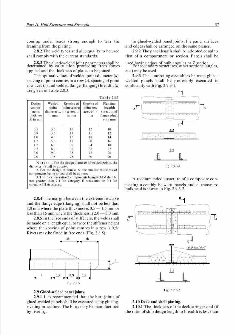
5/12/2018 High Speed Craft Rusa - slidepdf.com
http://slidepdf.com/reader/full/high-speed-craft-rusa 38/167
coming under loads strong enough to tear theframing from the plating.
2.8.2 The weld types and glue quality to be usedshall comply with the current standards.
2.8.3 The glued-welded joint parameters shall bedetermined by calculation proceeding from forcesapplied and the thickness of plates to be joined.
The optimal values of welded point diameter (d ),spacing of point centres in a row (t), spacing of pointrow aces (c) and welded flange (flanging) breadth (a)are given in Table 2.8.3.
2.8.4 The margin between the extreme row axisand the flange edge (flanging) shall not be less than8,0 mm where the plate thickness is 0,5 Ð 1,5 mm orless than 15 mm where the thickness is 2,0 Ð 3,0 mm.
2.8.5 In the free ends of stiffeners, the welds shallbe made on a length equal to twice the stiffener heightwhere the spacing of point centres in a row is 0,5t.Rivets may be fitted in free ends (Fig. 2.8.5).
2.9 Glued-welded panel joints.
2.9.1 It is recommended that the butt joints of glued-welded panels shall be executed using glueing-riveting procedure. The butts may be manufacturedby riveting.
In glued-welded panel joints, the panel surfacesand edges shall be arranged on the same planes.
2.9.2 The panel length shall be adopted equal tothat of a compartment or section. Panels shall be
used having edges of bulb angular or Z section.For secondary structures, other sections (angles,
etc.) may be used.2.9.3 The connecting assemblies between glued-
welded panels shall be preferably executed inconformity with Fig. 2.9.3-1.
A recommended structure of a composite con-
necting assembly between panels and a transversebulkhead is shown in Fig. 2.9.3-2.
2.10 Deck and shell plating.
2.10.1 The thickness of the deck stringer and (if the ratio of ship design length to breadth is less than
Designcompo-
nentsthicknessS , in mm
Weldedpoint
diameter d ,in mm
Spacing of point centresin a row, t,
in mm
Spacing of point rowaces, c, in
mm
Flangingbreadth
(breadth of flange edge),
a, in mm
0,50,81,01,21,52,53,02,0
3,03,54,05,06,08,09,07,5
1013151720303525
1215182024364230
1012141618222620
N o t e s : 1. For the design diameter of welded points, thediameter d shall be adopted.
2. For the design thickness S , the smaller thickness of components being joined shall be adopted.
3. The thickness ratio of components being welded shall benot greater than 2:1 for category II structures or 3:1 forcategory III structures.
T a b l e 2.8.3
Fig. 2.8.5
B
A A
B
A-A
B-B
Fig. 2.9.3-1
B
A A
BA-A
Bulkhead shelf
B-B
Fig. 2.9.3-2
Part II. Hull Structure and Strength 37

5/12/2018 High Speed Craft Rusa - slidepdf.com
http://slidepdf.com/reader/full/high-speed-craft-rusa 39/167
5,0) the thickness of deck plating adjacent to long-itudinal bulkheads shall be 20 per cent greater thanthickness of deck plating. The breadth (in meters) of deck stringer and thickened plates near by long-
itudinal bulkheads shall be not less than the valuedetermined by the formula:
b=0,014L+0,1. (2.10.1)
In the ship's ends as well as for the lower decks(pontoon plating) increment of the thickness of deckstringers and plates adjacent to the longitudinalbulkheads is not required.
2.10.2 Connection of the sheer strake to the deckstringer and strengthened deck plates to longitudinalbulkheads shall be made by the double-sided welds.
It is recommended to round connection of thesheer strake to the deck stringer. Sheer strakerounding radius shall be equal to at least its 20thicknesses.
2.10.3 If deck is discontinued in any compart-ment (for instance, engine room) then side stringersof increased height shall be mounted in the plane of deck along side. Connection of side stringers to thedeck continuation (and transverse bulkheads) isrecommended to apply to Figs. 2.10.3-1 and 2.10.3-2.
2.10.4 Shell plates and deck plating in the fixingpoints of bottom bearers, pylons, stanchions, shaftbrackets, stabilizers and hydrofoil installations shallbe 20 per cent greater while shell plates exposed tosignificant mechanical wear shall be 40 per centgreater than thickness of adjacent plates outside thearea of increased wear.
If all-pressed boards are used for the shell platingthe said thickening of plating is allowed to be made
by installation of superimposed plates welded byperimeter.
2.11 Superstructures and deckhouses.
2.11.1 Superstructures which length is three timesgreater than their height and deckhouses which aresupported at least by 3 rigid transverse members(bulkheads, transverse frames supported by cross tiesetc.) are treated as a solid one.
2.11.2 Reduction of the superstructure (deck-house) contribution to the total bending of ship hullis allowed due to:
use of movable (expanding, flexible or sliding)
joints along perimeter of the deckhouse section;supporting of deckhouse by two rigid transverse
members of hull (transverse bulkheads, web beamssupported by cross ties etc.).
2.11.3 Stanchions of the superstructure walls anddeckhouses shall be located in the plane of deckframing and fixed to the deck by brackets. If stanchionsdo not coincide with deck framing, stiffeners or otherstructures ensuring unload of a moment at a supportshall be provided under brackets.
2.11.4 Superstructure or deckhouse end bulk-heads shall be supported by transverse bulkheads.
Otherwise rounded brackets of sufficient size ensur-ing transmission of loads to the sides and pontoonshall be fitted under end bulkheads.
2.11.5 Door openings in longitudinal walls(including longitudinal bulkheads of superstructuresand deckhouses located within 0,6L amidships) shallbe supported by thickened plates above and belowopening.
Rounding of the opening corners is sufficient if the distance between expanding and sliding joints isless than three heights of superstructure (deckhouse).
Upper and lower edges of the side-scuttle open-ings shall be enforced by strengthened longitudinalmembers remoted from the opening edge at least by10S where S is the thickness of the superstructure
Side
Bulkhead
Fig. 2.10.3-1
Side
b - breadth of side stringer flange
Bulkhead
Fig. 2.10.3-2
38 Rules for the Classification and Construction of High-Speed Craft

5/12/2018 High Speed Craft Rusa - slidepdf.com
http://slidepdf.com/reader/full/high-speed-craft-rusa 40/167
(fast deckhouse) plating; meanwhile, opening cornersshall be additionally strengthened (Fig. 2.11.5).
2.11.6 If the window span in superstructure ordeckhouse is less than window width (for two ormore windows) plate thickness in the area of windowshall be enlarged by 40 per cent as opposed to
adjacent superstructure plates.2.12 Bulkheads.
2.12.1 Arrangement of longitudinal and trans-verse bulkheads shall be agreed with arrangement of stringers and floors. Longitudinal bulkheads shall bestrengthened by horizontal members.
2.12.2 Stanchions of transverse and longitudinalbulkheads as well as walls of superstructures anddeckhouses shall be located in the plane of bottomand deck framing.
Lower ends of stanchions shall be fixed on thehorizontal stiffener (Figs. 2.2.10-2 and 2.2.19-2) forthe floating framing system and conventional fram-
ing system of side-walls (with dead-rise of lines).If local operating loads are symmetrical relative to
the bulkhead and it is impossible to fix lower ends of stanchions on the horizontal stiffener, it is allowed toleave them unattached provided horizontal stiffener ismandatorily mounted on the opposite side of bulkheadplating (variant 2 on Figs. 2.2.19-1 and 2.2.19-4).
2.12.3 Ends of the longitudinal bulkhead stan-chions above stringers shall be fixed in accordancewith Figs. 2.2.10-3 and 2.12.3-1.
Ends of stanchions above carlings and beamsshall be fixed in accordance with Fig. 2.12.3-2.
2.12.4 Upper ends of the bulkhead stiffenerslocated outside area of intensive vibration (excluding
tank bulkheads) are allowed to snip.2.12.5 Stanchions of transverse and longitudinalbulkheads in the passages through permeable decksand platforms shall be continuous. These passagesshall be made in accordance with Fig. 2.12.5-1.
It is recommended to make intercostal verticalbulkhead stiffeners on the watertight decks (plat-forms) and secure them to the deck (Fig. 2.12.5-2).
2.12.6 The thickness of the bulkhead platingadjacent to the bottom shall be increased by 1 mm. If pressed boards are applied it is allowed not toincrease thickness.
2.12.7 Longitudinal bulkheads shall end on thetransverse bulkheads. They shall end by rounded
Fig 2.11.5
Bulkhead
Pontoon plating
(pressed board)
Stringer
(pressed board)
Fig. 2.12.3-1
b x b
o
Bulkhead
Fig. 2.12.3-2
Platform
Bulkhead
Fig. 2.12.5-1
Bulkhead (pressed board)
Platform(pressed board)
Fig. 2.12.5-2
Part II. Hull Structure and Strength 39

5/12/2018 High Speed Craft Rusa - slidepdf.com
http://slidepdf.com/reader/full/high-speed-craft-rusa 41/167
brackets (Fig. 2.12.7) connecting longitudinal bulk-head to the main deck and bottom longitudinalslocated in its plane (bottom stringers, carlings).
2.13 Bulwark.
2.13.1
Bulwark shall be fitted in places specifiedin Part III "Arrangements, Equipment and Outfit" of the Rules for the Classification and Construction of Sea-Going Ships.
Height of the bulwark measured from the upperedge of the gunwale shall comply with the require-ments of Part III "Arrangements, Equipment andOutfit" of the Rules for the Classification andConstruction of Sea-Going Ships.
2.13.2 Thickness of the bulwark plates, in mm, shallbe not less than the value determined by the formula:
S = 0,05L + 1,5. (2.13.2)
2.13.3 The thickness of the gunwale of bulwarkmade of strip or section material shall be at least by1 mm thicker that the bulwark plates. It is allowed touse light-wall tubes as a bulwark.
2.13.4 The bulwark shall be strengthened bystanchions at a distance not more than 1,2 m onefrom another.
Thickness of stanchions shall be at least by 1 mmgreater than thickness of the bulwark plates. Widthof the lower end of stanchion shall be not less thanthe width of the gunwale.
The width of the stanchion flange shall be not lessthan 60 mm.
If there are openings in the bulwark, thenstanchions adjacent to such openings shall bestrengthened.
2.13.5 Stanchions shall be located in the plane of underdeck framing, bulkheads or specially mountedstrengthenings and be secured to the deck, bulwarkand gunwale by welding or riveting.
2.14 Machinery foundation.
2.14.1 Foundations for ship machinery (engines,reduction gears, supercharging blowers etc.) shallhave stable and rigid structure ensuring reliablemounting of machinery to rigid hull members.Rigidity of machinery foundations and grillages on
which they are mounted shall comply with therequirements, technical standards applied to mount-ing and operation of such machinery.
2.14.2 Structural components and foundation
members shall be manufactured from the samematerial as the main case. Foundation and case shallbe connected by welding or riveting (see 2.5 and 2.7).
2.14.3 Foundation longitudinals under mainmachinery shall be aligned with bottom stringers orthere shall be provided additional members ensuringsmooth transmission of loads to hull.
2.14.4 Ends of foundation longitudinals shall beconnected with transverse bulkheads or reinforcedfloors and to finish by brackets located in the area of longitudinals and be attached to the transversemember (floors and web frames).
2.14.5
Webs of foundation longitudinals shall beby 40 per cent thicker than webs of bottom stringers.Deviation from these requirements is allowed if it is
justified by foundation strength and rigidity calcula-tion.
2.14.6 Horizontal face plates made of continuousstrips which thickness shall be by 40 per cent greaterthan thickness of plates of foundation wall shall bemounted on the upper edge of foundation long-itudinals.
Horizontal face plates of foundation longitudinalsin the area of securing bolts shall be strengthened byvertical brackets. Vertical size of these brackets shall be
not less than two times larger than their horizontal sizewhile thickness shall be equal or by 1 mm less thanthickness of the foundation walls.
2.14.7 Foundation longitudinals shall bestrengthened at each floor by transverse bracketsconnecting longitudinals together and by bracketsmounted on the outer side of longitudinals beginningfrom the center line of shaft. The width of bracketsshall be not less than their height while thickness _
20 per cent greater than thickness of floor webs. Freeedges of brackets for the length exceeding 40 thick-nesses of brackets shall have a face plate or flange.
Ends of face plates shall be snipped.2.14.8 There may be lightening openings in
brackets.2.14.9 It is allowed to make openings in the web
plate of foundation longitudinals. Openings shall bestrengthened.
2.14.10 Foundation girders under the hovercraftreducing gear transmitting rotation are subject to theRegister special consideration.
2.14.11 Foundations of small auxiliary machin-ery may be made as a bracket fixed on framing.Foundations shall be located on the least strainedparts of members in such a way that foundationsupporting components are mounted in the plane of web plate of framing.
Transverse bulkhead
Stringer
Longitudinal
bulkhead
Fig. 2.12.7
40 Rules for the Classification and Construction of High-Speed Craft

5/12/2018 High Speed Craft Rusa - slidepdf.com
http://slidepdf.com/reader/full/high-speed-craft-rusa 42/167
2.15 Platforms.
2.15.1 Scantlings of the platform framing shall beassigned on the basis of strength calculations.
Aluminium allows with inferior mechanical
properties as opposed to the main case material areallowed for use in platforms as well as three layerboards with aluminium and polymeric base layers.
It is recommended to align platform stiffenerswith vertical framing (frames, bulkhead stiffeners).
2.15.2 It is recommended to use zee, bulb angle,angle beams as the platform stiffeners.
2.16 Enclosures.
2.16.1 The following requirements refer to thestrengthened enclosures which support web frames.
2.16.2 Thickened plates shall be provided in thelower and upper parts of enclosures. Their width
shall be not less than two heights of frames passingthrough them and thickness:equal to the thickness of frame webs passing
through the lower part of framing _ for the upperpart;
increased by 1Ð2 mm relative to frame webs _
for the lower part.2.16.3 Plating of enclosures shall be strengthened
by zee, bulb angle, angle stiffeners. Stanchions maybe affixed to plating by glued-welded joint, glued-riveting joint, seam welding or riveting.
Bending (clamping) of vertical edges of platesmay substitute metal sections. Connection of plates
throughout bulkhead width shall be made by rivetingor contact welding of bent edges.
It is allowed to use horizontal or vertical box-shaped or wavy corrugated bulkheads and three-layerboards.
2.16.4 Door openings in enclosures shall bestrengthened by thickened plate or additional stiffen-ers.
2.17 Structural features of connecting bridges of
speed catamarans and side-wall hovercraft.
2.17.1 Main structures of connecting bridge shallbe all-welded from plates, section and all-pressed
boards. Plates of structures shall be strengthened bytransverse frames (web frames or brackets).
2.17.2 Structures of the connecting bridge in thebow end within 0,35L shall be made in accordancewith the conventional framing system.
2.17.3 It is recommended to connect transverseframes of connecting bridge with web frames asshown in Figs. 2.17.3-1 and 2.17.3-2.
2.17.4 It is recommended to fit together connect-ing bridge to the transverse bulkheads by means of thickened plates in the area of transition of connect-ing bridge plating to the bulkhead plating orelongation of reinforced web of the bridge frameand its smooth transition to the bulkhead plating(Figs. 2.17.4-1 and 2.17.4-2).
It is allowed to use web permeable bridgestructures amidships (within 0,25L to both ends fromthe midship section) (Fig. 2.17.4-2).
Deck
Outboard side
Inboard side
Conventional
centreline
Fig. 2.17.3-1
Deck
Inboard side
Fig. 2.17.3-2
Conventional centreline
Outboard side
Deck Strengthened plate of the web
frame included into bulkhead
Inboard side
Fig. 2.17.4-1
Part II. Hull Structure and Strength 41

5/12/2018 High Speed Craft Rusa - slidepdf.com
http://slidepdf.com/reader/full/high-speed-craft-rusa 43/167
2.18 Special features of the hovercraft hull
structures.
2.18.1 Apron.
2.18.1.1 Usually apron is made of the all-weldedplates, sections and all-pressed boards.
2.18.1.2
The thickness of the apron plating ischosen on the basis of the strength properties and itshall be taken not less than the deck thicknessdesigned for wheeled cars.
2.18.1.3 Dimensions of the apron members areassigned on the basis of strength calculations.
2.18.2 Skirt bag.
2.18.2.1 Usually skirt bag is riveted of plates,sections and boards.
Upon the Register approval it is allowed to weldskirt bag or make it from non-metal materials.
It is recommended to use bulb angle and zeebeams as longitudinals.
2.18.2.2 The thickness of the skirt bag platesadjacent to side which is not less than 300 mm shallbe 20 per cent greater than thickness of the rest skirtbag thickness.
Strengthened skirt bag plate is connected to theside by welding.
2.18.2.3 Part of skirt bag made of the pressedboards shall be strengthened by web beams.
2.18.2.4 Flexible skirt shall be continuouslysecured along length of skirt bag.
2.18.3 Side-walls.
2.18.3.1 Side-walls shall be made of welded
plates, sections and pressed boards. Parts of side-walls exposed to hydrodynamic blows shall be madeaccording to the conventional framing system.
2.18.3.2 Boards (welded, pressed boards) of side-walls shall be strengthened by brackets or web frames.
2.18.3.3 Bottom and side plating of side-walls areconnected by the double-sided welds.
2.18.4 Pylons.
2.18.4.1 Pylons shall be riveted (glued-riveted)from the plates, sections and all-pressed boards.
2.18.4.2 Boards of pylons (riveted boards withthe stiffeners of bulb angle and zee beams) shall bestrengthened by horizontal (rib) and vertical (spar)brackets.
Vertical brackets shall be continuous.
2.18.4.3 Thickness of pylon plating adjacent tothe foundation under pylon shall be at least 40 percent greater than the thickness of pylon plating.
Pylon shall be connected to the engine gondola
and foundation on casing by riveting (bolts).2.18.5 Air trunks.
2.18.5.1 It is recommended that air trunks shallbe glued-riveted from plates, sections and all-pressedboards. It is allowed to weld or rivet trunk structure.
It is recommended to use bulb angle and zeestiffeners as vertical stanchions.
2.18.5.2 Thickness of trunk shell ring adjacent tothe plating shall be 10 Ð 20 per cent greater thanthickness of plates of shell ring.
2.18.5.3 Recommended structural scheme of theair trunk is set forth in Fig. 2.18.5.3.
Trunk shell ring shall be strengthened byhorizontal framing (rings) located on the outer sideof the shell ring.
2.19 Hull structural features of the hydrofoils and
gliders.
2.19.1 Stem.
2.19.1.1 Usually, stems are riveted from plates.2.19.1.2 Thickness of the welded stem plates (in
mm) shall be at least:
S = 1,2 (0,05L +3). (2.19.1.2)
Longitudinal bulkhead
Transverse bulkhead
Tubular rod
Fig. 2.17.4-2
Top view
Deck
StiffenerHorizontal stiffener (ring)
Fig. 2.18.5.3
42 Rules for the Classification and Construction of High-Speed Craft

5/12/2018 High Speed Craft Rusa - slidepdf.com
http://slidepdf.com/reader/full/high-speed-craft-rusa 44/167
Accepted thickness of the stem plates shall be notless than the thickness of the horizontal keel in thespot of its connection to the stem.
The width of the stem transverse section, in mm,
measured in the waterline plane in the waterdisplacement mode shall be at least (2,5L+200).
2.19.1.3 Usually, stem plates shall be strength-ened by horizontal brackets mounted at most each0,5 meter. Arrangement of brackets throughout stemheight shall be, if possible, accorded with the hullframing. If distance between brackets is reduced to0,3 m it is allowed to reduce stem plates thickness by20 per cent as opposed to the value given in 2.19.1.2.However, in all cases thickness of stem plates shall benot less than the thickness of adjacent shell plating.
2.19.1.4 Thickness of brackets shall be equal to
the thickness of shell plating adjacent to the stem.2.19.1.5 Brackets shall overlap butts between stemand shell plating by the value of at least 10 thicknessesof the latter and, if possible, reach the nearest frameand be welded to them. Brackets which cannot beconnected to the framing shall have edge which ends onthe shell plating which is shaped by smooth curve.
2.19.1.6 The stiffener (plate) with face plate onthe free edge shall be mounted in the centreline fromkeel to the deck. Thickness of web and flange of stiffener shall be not less than the value adopted fortransverse brackets.
2.19.2 Strengthening of hull in the area of struts
and brackets of hydrofoil installations and shafts.2.19.2.1 Usually, at least one longitudinal and
two transverse members (stringers, web frames orfloors, bulkheads) shall be under each strut orbracket of hydrofoil installation and shaft.
Additional members under struts and bracketsmay be required in some cases.
2.19.2.2 Shell plating in the area of struts andbrackets of hydrofoil installations and shafts shall havean increased thickness in accordance with 2.10.4.
2.19.2.3 Strengthened openings for examinationand painting of a hard-to-reach area are allowed in
strengthenings.2.19.2.4 Floating framing system in the area of
strengthenings, floors and web frames shall be weldedto the shell plating (see 2.1.14).
2.19.2.5 Welding of superimposed plates made of the hull material is allowed from the outer side of shell plating in the areas of strengthening of bracketsof hydrofoil installations and shafts. Thickness of plates shall be at least double thickness of the shellplating in the area of the installation.
Plate thickness shall be such that the distancebetween a plate weld and flange edge shall be not lessthan three thicknesses of a plate.
Insulating gaskets shall be used when steel bracketsare connected to plates if brackets are made of steel.
3 REQUIREMENTS FOR HYDROFOIL INSTALLATION
DESIGN
3.1 General.
3.1.1 The general arrangement of a hydrofoilinstallation, location and dimensions of main andauxiliary planes, stabilizers, brackets, and stanchions,as well as the shape of hydrofoil installationcomponent cross-sections shall be chosen with dueregard for ensuring the required hydrodynamicalcharacteristics. The most rational structural layoutfor the hydrofoil installation shall be adopted inorder to ensure its strength.
3.1.2 The main plane and lower stanchion andstabilizer sections adjoining thereto shall be generallymade solid.
In the surfaces of non-tight hydrofoil compo-nents, two openings shall be drilled, one in the uppersurface and the other in the lower surface.
In the hollow, tight hydrofoil installation com-ponents, drain plugs shall be provided for waterdischarge.
3.1.3 Hydrofoil installation components of solidstructure shall be made of a single plate. Auxiliary(take-off) components of the hydrofoil installationshall be manufactured from aluminum-magnesiumalloys, and they shall be solid.
3.1.4 Hollow components of hydrofoil installa-tions whose structure is tight shall be tightness-tested
by filling with water with a head of 50 kPa or by airblowing under an over pressure of 20 kPa.
3.2 Main plane.
3.2.1 The main plane shall be continuous alongthe span and shall not be intercostal in way of stanchions. When the dead-rise angle of main planeor the setting angles of its components are modified,the plane may be partitioned in way of stanchions(Fig. 3.2.1).
3.2.2 Where the hydrofoil is of a hollowstructure, the stiffeners shall be arranged along itsspan (Fig. 3.2.2-1).
Stiffeners may be used which are fitted along thehydrofoil chord (Fig. 3.2.2-2). Each stiffener shall be
Fig. 3.2.1
Part II. Hull Structure and Strength 43

5/12/2018 High Speed Craft Rusa - slidepdf.com
http://slidepdf.com/reader/full/high-speed-craft-rusa 45/167
welded to the upper or lower section of hydrofoilplating.
Stiffeners fitted along the span shall be connectedto the upper plating of main plane and to the lower
plating of the take-off plane without use of thetransition shaller (Fig. 3.2.2-1).
3.2.3 Where a hollow hydrofoil is adjoined byother structures (stanchions, stabilizers), provisionshall be made for solid inserts in the hydrofoil, madeof thick plates or forgings (Fig. 3.2.3-1), and in the
adjoing structures provision shall be made forthickened plates (Fig. 3.2.3-2).
Thickened plates strengthened with additionalstiffeners or brackets (Fig. 3.2.3-3) shall be usedinstead of solid inserts.
The plates shall be fitted symmetrically with regardto the neutral axis of the hollow component plating.
3.3 Stabilizers, stanchions and brackets.
3.3.1 All the requirements of 3.2 apply to thedesign of stabilizers and stanchions.
The lower sections of hollow structures of stabilizers and stanchions adjoining the main planeshall be strengthened with solid inserts or withthickened plates reinforced with additional stiffenersor brackets.
3.3.2 The stiffeners of a hollow stabilizer shall bearranged along its span. In case there is no solid
Main plane Centre plane
Upper plating
Stiffener
Transition shaller
Fig. 3.2.2-1
C
C CL
C-C
Fig. 3.2.2-2
Fig. 3.2.3-1
Fig. 3.2.3-2
Fig. 3.2.3-3
44 Rules for the Classification and Construction of High-Speed Craft

5/12/2018 High Speed Craft Rusa - slidepdf.com
http://slidepdf.com/reader/full/high-speed-craft-rusa 46/167
insert between the main plane and stabilizer, thestabilizer stiffeners shall be arranged in such a way asto form a continuation of the main plane stiffeners, asshown in Fig. 3.3.2.
3.3.3 The stiffeners of the hollow section of astanchion shall be arranged along the stanchion. The
stiffeners shall be attached to the shell plating inaccordance with the requirements of 3.2.2.3.3.4 A stanchion shall be attached to the hull by
means of a vertical, horizontal or inclined flange. Theinput edge of the stanchion shall be rounded wherethe stanchion is attached to the main plane andflange to ensure a smooth transition in way of abutments (Fig. 3.3.4).
3.3.5 Side brackets shall have a hollow structure.The stiffeners of side brackets shall be arranged
along the length of the latter. The stiffeners shall be
attached to the shell plating as stipulated in 3.2.3. Onthe input and emergent edges of the bracket,connecting elements of solid cross-section shall befitted.
3.4 Welded joints.
3.4.1 General.
3.4.1.1 In hydrofoil installations, the welded jointassemblies shall be located in areas with the loweststresses.
3.4.1.2 The weld types and structural elements of edge preparation for welding shall be in accordancewith the standards agreed with the Register.
3.4.1.3 On water-washed surfaces, the butt-weldstrengthening shall be machined flush with the basemetal and ground.
3.4.1.4 On water-washed surfaces, fillet weldsshall be ground so as to ensure a smooth transition tothe base metal.
3.4.2 Butt welds.
3.4.2.1 The butt welds in solid components of hydrofoils shall be made using direct welding withdouble-groove edge preparation.
3.4.2.2 The plates of hollow hydrofoils shall beconnected to each other and to other elements of external hydrofoil surface by means of butt weldswith edge preparation (direct or indirect welding witha backing run). Where the opposite side is inacces-sible for welding, butt welds shall be made on apermanent backing or halved (Fig. 3.4.2.2). Thebacking material shall be of the same grade as thebase metal.
The upper plating of main plane and the lowerplating of the take-off surface of a hydrofoil shall beconnected to the end elements (fillers) by means of direct butt welds.
3.4.2.3 The stiffener flanges forming a part of thehollow-hydrofoil shell plating shall be connected tothe shell plating in conformity with Fig. 3.4.2.2.
3.4.3 Tee joints.
3.4.3.1 The tee and fillet joints of solid hydrofoilcomponents shall be made by double-groove weldingwith full penetration. If the plate being joined is morethan 1,5 times thicker than the plate to which it is
joined and its thickness is equal to or greater than 40mm in a tee joint, double-groove welding without fullpenetration shall be used. In this case, the design
Fig. 3.3.2
B
B-B
B
Fig. 3.3.4
55S
510S >2
S
S
55S
StiffenerStiffener flange
Backing
Shell plate
Stiffener flange Stiffener
Shell plate
Stiffener
Shell plate End element
Fig. 3.4.2.2
Part II. Hull Structure and Strength 45
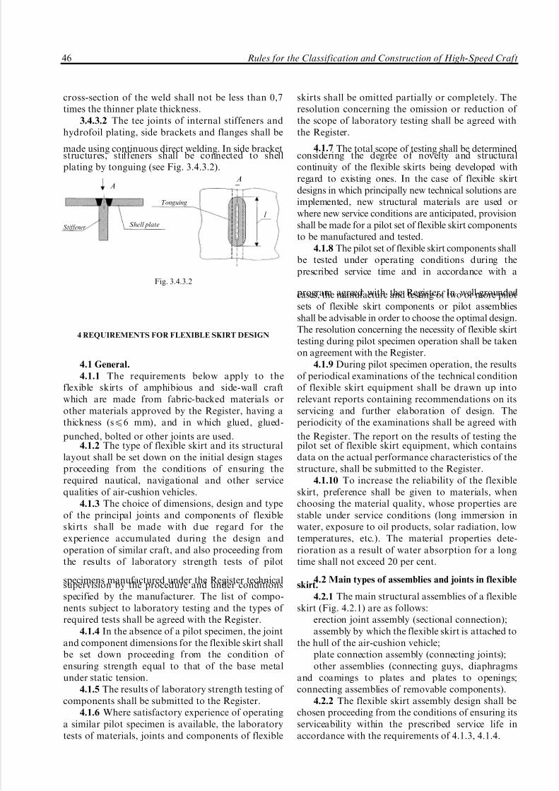
5/12/2018 High Speed Craft Rusa - slidepdf.com
http://slidepdf.com/reader/full/high-speed-craft-rusa 47/167
cross-section of the weld shall not be less than 0,7times the thinner plate thickness.
3.4.3.2 The tee joints of internal stiffeners andhydrofoil plating, side brackets and flanges shall be
made using continuous direct welding. In side bracketstructures, stiffeners shall be connected to shellplating by tonguing (see Fig. 3.4.3.2).
4 REQUIREMENTS FOR FLEXIBLE SKIRT DESIGN
4.1 General.
4.1.1 The requirements below apply to theflexible skirts of amphibious and side-wall craftwhich are made from fabric-backed materials orother materials approved by the Register, having athickness (s46 mm), and in which glued, glued-
punched, bolted or other joints are used.4.1.2 The type of flexible skirt and its structural
layout shall be set down on the initial design stagesproceeding from the conditions of ensuring therequired nautical, navigational and other servicequalities of air-cushion vehicles.
4.1.3 The choice of dimensions, design and typeof the principal joints and components of flexibleskirts shall be made with due regard for theexperience accumulated during the design andoperation of similar craft, and also proceeding fromthe results of laboratory strength tests of pilot
specimens manufactured under the Register technicalsupervision by the procedure and under conditionsspecified by the manufacturer. The list of compo-nents subject to laboratory testing and the types of required tests shall be agreed with the Register.
4.1.4 In the absence of a pilot specimen, the jointand component dimensions for the flexible skirt shallbe set down proceeding from the condition of ensuring strength equal to that of the base metalunder static tension.
4.1.5 The results of laboratory strength testing of components shall be submitted to the Register.
4.1.6 Where satisfactory experience of operatinga similar pilot specimen is available, the laboratorytests of materials, joints and components of flexible
skirts shall be omitted partially or completely. Theresolution concerning the omission or reduction of the scope of laboratory testing shall be agreed withthe Register.
4.1.7 The total scope of testing shall be determinedconsidering the degree of novelty and structuralcontinuity of the flexible skirts being developed withregard to existing ones. In the case of flexible skirtdesigns in which principally new technical solutions areimplemented, new structural materials are used orwhere new service conditions are anticipated, provisionshall be made for a pilot set of flexible skirt componentsto be manufactured and tested.
4.1.8 The pilot set of flexible skirt components shallbe tested under operating conditions during theprescribed service time and in accordance with a
program agreed with the Register. In well-groundedcases, the manufacture and testing of two or more pilotsets of flexible skirt components or pilot assembliesshall be advisable in order to choose the optimal design.The resolution concerning the necessity of flexible skirttesting during pilot specimen operation shall be takenon agreement with the Register.
4.1.9 During pilot specimen operation, the resultsof periodical examinations of the technical conditionof flexible skirt equipment shall be drawn up intorelevant reports containing recommendations on itsservicing and further elaboration of design. Theperiodicity of the examinations shall be agreed with
the Register. The report on the results of testing thepilot set of flexible skirt equipment, which containsdata on the actual performance characteristics of thestructure, shall be submitted to the Register.
4.1.10 To increase the reliability of the flexibleskirt, preference shall be given to materials, whenchoosing the material quality, whose properties arestable under service conditions (long immersion inwater, exposure to oil products, solar radiation, lowtemperatures, etc.). The material properties dete-rioration as a result of water absorption for a longtime shall not exceed 20 per cent.
4.2 Main types of assemblies and joints in flexibleskirt.
4.2.1 The main structural assemblies of a flexibleskirt (Fig. 4.2.1) are as follows:
erection joint assembly (sectional connection);assembly by which the flexible skirt is attached to
the hull of the air-cushion vehicle;plate connection assembly (connecting joints);other assemblies (connecting guys, diaphragms
and coamings to plates and plates to openings;connecting assemblies of removable components).
4.2.2 The flexible skirt assembly design shall bechosen proceeding from the conditions of ensuring itsserviceability within the prescribed service life inaccordance with the requirements of 4.1.3, 4.1.4.
Tonguing
Shell plateStiffener
AA
l
Fig. 3.4.3.2
46 Rules for the Classification and Construction of High-Speed Craft

5/12/2018 High Speed Craft Rusa - slidepdf.com
http://slidepdf.com/reader/full/high-speed-craft-rusa 48/167
4.2.3 Aluminium rivet joints are recommendedinstead of punched joints for highly loaded flexibleskirt assemblies made of high-strength materials(breaking strength of 4,000 N/m or above).
4.3 Flexible skirt design.
4.3.1 The design of the flexible skirt shall ensureits reliable operation under any service conditionsand under the service factors specified in the requestfor proposal.
4.3.2 To ensure the serviceability and repairability
of the flexible skirt during its service life it shall be sodesigned as to make replacement of componentspossible which are subject to accelerated wear.
4.3.3 The connecting assemblies shall not involvedamage to adjacent flexible-skirt components. Themetal components of flexible-skirt connecting assem-blies shall be made of corrosion-resistant materials orshall have a corrosion-resistant coating.
4.3.4 All materials applied in the flexible-skirtstructure shall comply with specified service condi-tions and loads and shall have the smallest masspossible.
4.3.5 The flexible-skirt structure shall, as far aspracticable, be simple, producible, easy to operateand to maintain, to assemble and to disassemble and
shall provide the possibility to make replacement of worn components from the outside and repair workaboard the craft possible.
In well-grounded cases, the flexible skirt structure
shall incorporate erection joints in order to facilitateits manufacture, assembly, disassemble and repair.As far as practicable, the flexible-skirt sections shallbe standardized.
4.3.6 Openings for air supply from the flexibleseal to the removable components of the flexible skirtshall, as far as practicable, be as small as possible. Anincrease in the number of openings is recommendedto provide the necessary air-flow area.
4.3.7 The request for proposal made in connec-tion with the flexible skirt development shall containtechnical requirements for the flexible skirt design,
taking into consideration the structural peculiaritiesand anticipated service conditions of the craft.
5 STRENGTH NORMS
5.1 General.
5.1.1 The present norms set requirements putforward by the Register for the strength andreliability of hull structures and special devices of the high speed crafts (including dynamically sup-ported ships) as well as for performance verificationstrength calculations.
The strength norms are obligatory in design,construction and conversion of ships which arecovered by these norms and technical projectssubmitted to the Register.
5.1.2 Deviation from the present strength normsor application of other methods of calculation of main hull structures shall be allowed by the Registerif sufficient justifications are available.
5.1.3 Strength calculations performed in accor-dance with the present norms shall be available for theexhaustive verification of all initial data containedtherein. After approval of the project by the Register,
responsibility still rests with the design bureaus forpossible consequences which shall take place as a resultof calculation errors or other omissions.
N o t e : If strength calculations are made on PCs, softwareused for such calculations shall be certified by the Register.
5.1.4 Strength calculations of hull structures andspecial arrangements shall check finally determineddimensions of these structures at a given nominalthickness of applied plates, panels, materials.
5.1.5 Strength calculations submitted to theRegister shall include:
external force calculations for general and localhull strength;
external force calculations for special arrange-ments strength;
Metallic loop
Bolted joint
Erection joint assembly Hull attachment assembly
Punch
Plate connection assembly Guy / diaphragm connection assembly
Rubber
coated washer
Coaming connection assembly
Removable component hull
attachment assembly
Fig. 4.2.1
Part II. Hull Structure and Strength 47

5/12/2018 High Speed Craft Rusa - slidepdf.com
http://slidepdf.com/reader/full/high-speed-craft-rusa 49/167
general hull strength calculation;local hull strength calculation;calculation of strength of special arrangements;results of experimental strength research of
components and joints of hull and special arrange-ments (if such researches are stipulated);
strength conclusion made upon results of testingof the prototype (experimental) ship.
5.1.6 Calculations of the general and local hullstrength, strength of special arrangements shallconfirm that if design loads are applied, maximumnormal and tangential stresses as well as maximumstrain in flexible skirt do not exceed allowed limitsgiven in 5.2 as well as sufficient strength margin forultimate loads.
5.1.7 Besides verification of structure resistance
to stresses, rigidity of the whole structure and of itscomponents shall be tested, if this is required by thepresent norms and structure operating condition.
5.1.8 Stability of superstructure, bottom and sidewall deck longitudinals as well as carlings, bottomstringers and vertical keel in grillage shall be ensuredwith at least two times safety margin as opposed todesign calculation of general bending of hull corre-sponding to design section under review.
For hovercrafts and high speed catamarans withsuch margin strength, resistance of frames and beamsto design stresses caused by transverse generalbending of hull shall be ensured.
5.1.9 Loss of resistance of shell plating and deckplating of superstructure is allowed if design stressesare caused by general bending of hull.
5.1.10 When making calculation of framesrigidity it is necessary to consider influence of
variation of the material elasticity by the value of critical normal stress (Fig. 5.1.10); this considerationis not applied to plates.
5.1.11 Generally, strength calculation shall in-
clude the following:determination of the value and character of
design loads;determination (in relation to the stressed condi-
tion) of maximum normal and tangential stress insections of structures for the given design loads;
assignment of norms for dangerous stresses;assignment of the required safety margin, norms
of permissible stresses and verification of strengthconditions.
5.1.12 External loads applied to ship hull and itsseparate structures shall be determined for the
hardest operational conditions. Maximum externalforces expected over the whole service life shall betaken for design loads.
5.1.13 Verification of strength conditions andresistance shall be carried out for the maximumnormal and tangential stresses depending on thestressed condition of structure.
5.1.14 When stresses are calculated in thestructural sections, loss of rigidity by some platesshall be considered by introduction of appropriatereducing coefficients.
When tangential stresses are determined, plateswhich have lost rigidity due to shift shall be
introduced with the reducing coefficient:
j= 0,65. (5.1.14)
5.1.15 Scantlings of members which are notcalculated by the norms shall be chosen in accor-dance with recommendations set forth in Sections2Ð4 of the present Rules.
5.1.16 Required duration of operating life of main (type) components and joints determined inaccordance with 5.2.18 shall be ensured for hull andspecial arrangements.
For structures differing from typical ones, theiroperating life determined by the technical request forthe design shall be supported not only by safetymargins but by thorough fitting components of thesestructure, assessment of their operating life keepingdue note of experimental researches as well asperformance of periodical surveys and repairs duringoperation.
5.2 Norms for permissible stresses.
5.2.1 Values of permissible stresses in general andlocal hull strength calculations shall be taken inaccordance with 5.2.8, 5.2.14 as a proportion of dangerous stresses.
5.2.2 Dangerous condition of structures duringassessment of its strength is considered such state
scr/R p02 1.0
0.9
0.8
0.7
0.6
0.5
0.4
0.3
0.2
0.1
0.0 0.5 1.0 1.5 2.0 2.5 3.0 3.5
se/R p02
aluminium alloyssteels
se _ Euler's stressesscr _ crippling stresses
Fig. 5.1.10
48 Rules for the Classification and Construction of High-Speed Craft
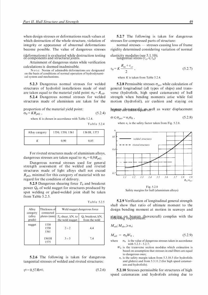
5/12/2018 High Speed Craft Rusa - slidepdf.com
http://slidepdf.com/reader/full/high-speed-craft-rusa 50/167
when design stresses or deformations reach values atwhich destruction of the whole structure, violation of integrity or appearance of abnormal deformationsbecome possible. The value of dangerous stresses
(deformations) is evaluated while destruction testingof components and structural joints.
Attainment of dangerous states while verificationcalculations is deemed inadmissible.
N o t e : Norms of admissible deformations are designatedon the basis of conditions of normal operation of hydrodynami-cal system and mechanisms.
5.2.3 Dangerous normal stresses for weldedstructures of hydrofoil installations made of steelare taken equal to the material yield point s0=ReH .
5.2.4 Dangerous normal stresses for weldedstructures made of aluminium are taken for the
proportion of the material yield point:s0=KR p02 , (5.2.4)
where K is chosen in accordance with Table 5.2.4.
For riveted structures made of aluminium alloys,dangerous stresses are taken equal to s0=0,9R p02.
Dangerous normal stresses used for generalstrength assessment of the welded and rivetedstructures made of light alloys shall not exceedR p02, minimal for this category of material with noregard for the condition of delivery.
5.2.5 Dangerous shearing force T 0 and breakoutpower Q 0 of weld nugget for structures produced byspot welding or glued-welded joint shall be takenfrom Table 5.2.5.
5.2.6 The following is taken for dangeroustangential stresses of welded and riveted structures:
t0=0,57R p02. (5.2.6)
5.2.7 The following is taken for dangerousstresses for compressed parts of structure:
normal stresses _ stresses causing loss of framerigidity determined considering variation of normal
elasticity modulus (see 5.1.10);tangential stress (tcr4tn)
t0=K Rm+tcr
2, (5.2.7)
where K is taken from Table 5.2.4.
5.2.8 Permissible stresses s per while calculation of general longitudinal (all types of ships) and trans-verse (hydrofoils, high speed catamarans) of hullstrength when bending moments arise while foilmotion (hydrofoil), air cushion and staying on
bearers (hovercraft) as well as water displacementregime are taken equal to:
s4s per=nss0 , (5.2.8)
where ns is the safety factor taken from Fig. 5.2.8.
5.2.9 Verification of longitudinal general strengthshall show that ratio of ultimate moment to thedesign bending moment at motion in seaways and
staying on bearers (hovercraft) complies with thefollowing requirement:
M ult/M des5ns;
M ult = s0W 0 , (5.2.9)
where s0 is the value of dangerous stresses taken in accordancewith 5.2.3 - 5.2.7;
W 0 is the transverse section modulus which estimation isbased on assumption that stresses in end fibers are equalto dangerous ones;
ns is the safety margin taken from 5.3.10.5 (for hydrofoilsand gliders) and from 5.3.11.2 (for high speed catamar-ans and hydrofoils).
5.2.10 Stresses permissible for structures of highspeed catamarans and hydrofoils arising due to
Alloy category 1530, 1550, 1561 1561H, 1575
K 0,90 0,85
T a b l e 5.2.4
Alloycategory
(alloygrade)
Thickness of connected
plates (mm)
Weld nugget dangerous force
T 0 shear, kN, tothe weld nugget
Q 0 breakout, kN,from the weld
nugget 153015501561
1561H1575
272
373
4,4
7,4
T a b l e 5.2.5
ns
05welded structures
riveted structures
0.4
0.7
1.1 1.2 1.3 1.4 1.5 1.6 1.7 1.8 1.9
Rm/s per
Fig. 5.2.8Safety margins for hull (aluminium alloys)
Part II. Hull Structure and Strength 49

5/12/2018 High Speed Craft Rusa - slidepdf.com
http://slidepdf.com/reader/full/high-speed-craft-rusa 51/167
tangential stresses arising in longitudinal and trans-verse hull bending as well as influence of longitudinaltorsion torque while motion at seaways and stayingon bearers are taken equal to:
t per = 0,30R p02 . (5.2.10)
5.2.11 Stresses permissible at calculation of localstrength of bottom, side, side wall plating (high speedcatamarans and hovercrafts) on plate contour forloads set forth in 5.4 are taken equal to:
s per = s0 . (5.2.11)
5.2.12 Stresses permissible at verification of localstrength of framing of bottom structures, side, deck
plating, superstructure deck, superstructure sides, bulk-heads, platforms as well as rigid skirt bags, side walls(hovercraft) and inside plate contours for application of loads set forth in 5.4 are taken equal to:
s per = 0,8s0 . (5.2.12)
5.2.13 Stresses permissible for application of normal stresses in carrying components of foils,struts, stanchions, stabilizers, brackets are takenequal to:
s per = nss0 , (5.2.13)
where ns is the safety margin taken from Fig. 5.2.13.
5.2.14 Stresses permissible for calculation of influence of shell plating strength and framing of
hollow components of hydrofoil installations on thehydrodynamic pressure arising due to flow about foilare taken equal to:
s per = 0,5s0 . (5.2.14)
5.2.15 See 5.5.1.7 and 5.5.1.9 for stability factorof stanchions, framing and plating of hollowcomponents by normal stresses.
5.2.16 Flexible skirt shall comply with thefollowing strength conditions:
KT 4Rb, (5.2.16)
where K is the safety factor assigned in accordance withTable 5.2.16.
5.2.17 Refinement of safety factor as regardsspecific project is carried out at the flexible skirtoperation testing stage of head complex.
5.2.18 Strength norms are based on respectivestrength margin considering specific working condi-tions and responsibility of each structure under
review.Structural requirements in conjunction with
special measures are aimed to ensure fatigue life of a large number of fatigue cracks in main (standard)
joints and components over the whole period of shipservice life.
5.2.19 Strength norms of permissible and danger-ous stress accepted in cases which are not provided bythe present Rules shall be justified and agreed withthe Register.
5.3 Hull general strength calculation.
5.3.1 General.
5.3.1.1 Hull general strength shall be verifiedduring following types of stressed/strained condi-tions:
ns
0.8
0.7
0.6
0.5
0.4
1.2 1.4 1.6 1.8 2.0
Rm/R p02 (Rm/ReH )
noncorrosive steel:solid componentshollow componentsaluminium alloys:
solid auxiliary components
Fig. 5.2.13
Design case Safety factor (K )
1. Flexible skirt general strength
Vaporing above surface without motion
Motion in specification seaways conditions
Motion in seaways conditions exceedingspecification parametres
14 (15)*
7 (5)
3,5
2. General strength of removable components
Motion in specification seaways conditions 10Ð15
3. General strength of guys and diaphragms
Motion in seaways conditions exceedingspecification parametres
5Ð7
* safety factor for flexible skirt of the side-wall hovercraftis given in brackets.
T a b l e 5.2.16
50 Rules for the Classification and Construction of High-Speed Craft

5/12/2018 High Speed Craft Rusa - slidepdf.com
http://slidepdf.com/reader/full/high-speed-craft-rusa 52/167
general longitudinal bending (all types of ships);general transverse bending (high speed catamar-
ans and hydrofoils);torsion (high speed catamarans and hydrofoils).
The following motion regimes shall be reviewed:navigation in water displacing state on seaways
designed in the project;hydrofoil motion (hydrofoils), motion at air
cushion (hovercraft), gliding (gliders) at design speedat design seaways.
5.3.1.2 The scope of general strength calculationsshall be defined by the designer depending on thearchitectural and design peculiarities of the ship andshall be agreed with the Register.
5.3.1.3 Verification of general strength shall becarried out for the full ship displacement for the most
representative from the strength standpoint transverse(all types of ships) and longitudinal (hydrofoils andcatamarans) hull sections: in the areas of maximumbending, torsion torque (hydrofoils and catamarans)and cutting forces; in the areas of large openings indeck, superstructure etc. at least in three transverse andtwo longitudinal hull sections (hovercraft and highspeed catamarans) where large stresses may be expected.
Number of sections verified lengthways andbreadthways (hovercraft and high speed catamarans)of hull shall be justified in strength calculationssubmitted to the Register.
5.3.1.4 Weight and external forces distribution
diagram as well as calculation of bending moments andcutting force made in accordance with consecutivechapters of the Rules shall be carried out by the numberof ordinates which shall be not less than the number of theoretical spacings assuming that distribution of loadsis equal along each area between such ordinatesprovided the latter is not conditioned separately.
The weight of ship ends lying beyond endordinates shall be fully considered as regards itsvalue and moment.
Non-closure of bending moment diagrams shallnot exceed 5 per cent of maximum ordinates of these
diagrams.5.3.1.5 The maximum moment applied amidships
at a distance of 5 per cent to the fore and aft end fromthe section where maximum bending moment iseffecting shall be taken for the design moment.
For the ship sections located beyond above-mentioned 10 per cent of ship length, the designbending moment is the maximum bending momenteffecting in the section located 5 per cent of shiplength away from the section under review.
5.3.1.6 Carlings, stringers and other carrying long-itudinal beams of bottom, side walls, decks, sides, skirtbags, etc. shall be fully included into calculation of hullgirder. If plates lose rigidity while compression andshear, the area of their section shall be reduced.
5.3.1.7 Rigidity of grillage during compression andshear shall be tested in general and of each componentseparately: frames, brackets, plates etc. This shall ensuresufficient rigidity of members supporting structure
affected by compressing and shearing loads.As regards elongated grillage without bulkheads
across its length it is allowed to consider variation of compressing loads over its length.
5.3.1.8 Vertification of the general strength forpermissible stresses shall be carried out by comparison of design normal stresses in end members of hull girderwith permissible stresses as well as the maximumtangential stresses against respective permissible stresses.
5.3.1.9 The values of bending moments applied tothe hydrofoil installation components, forces as wellas overloads are usually determined upon results of
testing respective models (tow elastic and self-propelled ones).Experimental data shall be compared with the
results of calculation following analytical dependen-cies given in the present Rules.
Modelling shall be carried out following princi-ples of Froude scaling.
Correction of results of model tests and strengthcalculations in order to specify strength and structur-al life of series ships shall be carried out upon resultsof sea-keeping tests of prototype ship strength onwhich basis technical and operational ship character-istics are finally determined.
5.3.1.10 Processing of model test data is carriedout by means of statistical methods. Meanwhile, thedesign value of the strength parameter with prob-ability of 0,975 and reliability of 0,950 shall exceedany value of strength parametre of 5 per centprovision obtained during tests.
N o t e : Strength parameter in this case means peak valuesof structural load level (bending moment, stresses, forces,overload etc).
5.3.1.11 Dimensions of self-propelled models andtheir water displacement as well as program of modeltests shall be submitted to the Register in the
technical design documentation.N o t e s :1. During testing the model shall pass at least 200 waves at
each regime.2. The number of regimes is at least 30.3. During testing of elastic models on the open water space
such testings are deemed valid at which realisation the height of 3 % exceedance level was at least 80 mm.
5.3.2 Evaluation of bending moments and cutting
forces applied to hydrofoil hull during navigation.
5.3.2.1 Navigation regime is the hydrofoil motionwith a speed of V hb4V lift on seaways in the waterdisplacing position specified in the technical design.
5.3.2.2 The value of the maximum bendingmoment amidships while sagging and hogging of ship hull is calculated according to the following
Part II. Hull Structure and Strength 51

5/12/2018 High Speed Craft Rusa - slidepdf.com
http://slidepdf.com/reader/full/high-speed-craft-rusa 53/167
formulae (the value of the bending moment is deemedpositive at sagging and negative at hogging):
M sagdes=M w+M sag
d ; (5.3.2.2-1)
M hogdes =M w+M hog
d , (5.3.2.2-2)
where M sag d =0,01K sagDL;
M hogd =0,01K hogDL;
Bending moment M w is evaluated by means of static wave simulation; coefficients K sag and K hog aretaken from Fig.5.3.2.2.
5.3.2.3 The value of cutting forces is calculatedaccording to the following formulae:
Q sag des=4|M sag
c |/L; Q hog des=4|M hogc |/L . (5.3.2.3)
5.3.2.4 Distribution of bending moments andcutting forces along ship hull is taken fromFig. 5.3.2.4.
5.3.3 Evaluation of design forces during hydrofoil
motion on foils.
5.3.3.1 General hull strength against externalforces arising at foil motion and speed motion
specified in design technical request shall be verifiedfor total displacement of the ship.
5.3.3.2 Hull general strength is tested for
resistance to weight, hull and equipment massmoments of inertia as well as lifting forces arisingin foil system and transmitted to hull in the form of concentrated forces.
5.3.3.3 Design values of cutting forces andbending moments are determined according to thefollowing formulae:
Q des=$x
0
mx g(n g+1)d x+s(x:7x fr)R+s(x:7xcent)R7p+
+s(x:7xaft)Raft;(5.3.3.3-1)
M des=$x
0
$x
0
mx g(n g+1)d xd x+s(x:7x fr)R fr(x+x fr7x:)+
+s(x:7xcent)R fr(x7xcent7x:)+
+s(x:7xaft)Raft(x+xaft7x:),(5.3.3.3-2)
where s(x) is Hevyside's unit function.
5.3.3.4 While determination of the inertial forcesof hull and carried cargoes, the value of thea c ce l er a ti o n i s t a ke n f r om F i g. 5 . 3. 3 .4 - 1.
The maximum design values of overloads whichdetermine inertial forces are calculated for the bow
k sag
15
14
13
12
11
10
9
8 1
7 2
6 3
5 4
4
3
2
1
0,1 0,2 0,3 0,4 0,5 0,6 0,7 0,8 0,9 1,0 1,1 1,2 1,3 1,4 1,5 1,6 1,7 1,8 1,9 2,0
71 F rD72
73
745
756
76 7 77 878
k hog
1 _ h=0,8; 2 _ h=0,7; 3 _ h=0,6; 4 _ h=0,55 _ h=0,5; 6 _ h=0,6; 7 _ h=0,7; 8 _ h=0,8
Fig. 5.3.2.2
Q /Q sag des, Q /Q hog des
1,0Q
0,8
0,6
0,4
0,20 20 19 18 17 16 15 14 13 12 11 10 9 8 7 6 5 4 3 2 1 0 Section
0,20 0,1 0,2 0,3 0,4 0,5 0,6 0,7 0,8 0,9 1,0
70,2Z/L
0,4 70,4
0,6 70,6
0,8m
70,8
1,0 71,0
M/|M sagdes|, M/|M hog
des |
Fig. 5.3.2.4
n g I
III
II II
nalf n fr
I n g
III c.g. Section
20 18 16 14 12 10 8 6 4 2 0
Fig. 5.3.3.4-1
52 Rules for the Classification and Construction of High-Speed Craft

5/12/2018 High Speed Craft Rusa - slidepdf.com
http://slidepdf.com/reader/full/high-speed-craft-rusa 54/167
perpendicular _ n fr, center of mass _ n g and20 sections _ naft respectively according to theformulae:
n fr=1+2,7P fr.s.w/D; (5.3.3.4-1)
n g=0,55+0,57P fr.s.w/D+Dng; (5.3.3.4-2)
naft=1,40, (5.3.3.4-3)
where Dn g is taken from Fig. 5.3.3.4-2.
If the hydrofoil automatic control system is
available, overloads reduce:for the ships with the surface piercing foil system
_ by 10 per cent;for the ships with the completely immersed foil
system _ by 20 per cent.
N o t e . The value of the relative acceleration may be revisedupon the results of experimental researches.
5.3.3.5 While ship motion on still water liftingforces acting upon the foils are:
for hydrofoils with double foil arrangementscheme (Pcent.st.w= 0) are calculated according to
the following formulae):
P fr.st.w.=Daaft/l f ; (5.3.3.5-1)
Paft.st.w=Da fr/l f . (5.3.3.5-2)
5.3.3.6 Hydrodynamic loads acting upon hull aredetermined keeping due note of dependencies:
R fr+Rcent+Raft=D(n g+1); (5.3.3.6-1)
R fr(x fr7x0)+Rcent(xcent7x0)+Raft(xaft7x0)=I y
x fr7x0
(n fr7n g).
(5.3.3.6-2)
5.3.3.7 Verification of hull general strength tocutting forces and bending moments is carried out inaccordance with 5.3.3.3 _ 5.3.3.6. While doing thisthree design load cases are reviewed:
maximum acceleration is acting in the bow endand distribution of accelerations along hull length istaken in accordance with the line IÐI (Fig. 5.3.3.4-1);for the double foil arrangement scheme Rcent=0 andfor three foil arrangement scheme it is takenR fr=Pmax
fr +0,3D; hull inertial forces are calculatedin accordance with distribution of accelerationsaccepted for such case;
equal distribution of accelerations along hulllength _ the line IIÐII (Fig.5.3.3.4-1); for the doublefoil arrangement scheme Rcent=0 and for three foilarrangement scheme it is taken Rcent=Pmax
cent+0,3D;
hull inertial forces are calculated in accordance withdistribution of accelerations accepted for such case;maximum acceleration is acting in aft end and
distribution of accelerations along hull length ist ak en i n a c co rd an ce w i th t he l i ne I I IÐ II I(Fig. 5.3.3.4-1); for the double foil arrangementscheme Rcent=0 and for three foil arrangementscheme it is taken Raft=Pmax
aft +0,3D; hull inertialforces are calculated in accordance with distributionof accelerations accepted for such case.
5.3.3.8 Maximum value of lifting forces acting inthe foil system are calculated by the formulae:
Pmax
fr =K frP fr.st.w; Pmaxcent=K centPcent.st.w; P
maxaft =K aftPaft.st.w. (5.3.3.8)
where K fr, K cent, K aft are coefficients which are calculated accordingto the formulae:
K fr= 1,68+1,26h3%/3HH70,42P fr.st.w./D;
K cent= 1,02+0,7h3%/3HH70,14l fr/3HH ;
K aft= 1,20+0,56h3%/3HH+0,24P
fr.st.w.
Paft.st.w.
6P
cent.st.w.
D.
5.3.3.9 Cutting forces and bending momentdiagrams for the whole hull length are plotted foreach case of loading upon results of the calculation.
General strength is verified for sagging of hull forthe double foil arrangement scheme. Envelope curveplotted upon maximum values obtained for all designcases of load in accordance with 5.3.3.7 is taken forthe design diagram.
Additionally, hull strength verification shall beperformed in case of hogging due to bending momentequal to M hog
des =0,5M sagdes.
Verification of the general strength of the threefoil arrangement scheme is carried out for the twofollowing cases:
sagging; values of the envelope curve of the twodiagrams obtained for the first and third design caseif they correspond to 5.3.3.7 are taken for the designbending moments. Additionally, verification of the
Dn g
1,8
1,6
1,4
1,2
1,0
0,8
0,6
0,4
0,2
hcl =hcl
h3%
0,1 0,2 0,3 0,4 0,5 0,6
Fig. 5.3.3.4-2
Part II. Hull Structure and Strength 53

5/12/2018 High Speed Craft Rusa - slidepdf.com
http://slidepdf.com/reader/full/high-speed-craft-rusa 55/167
general strength is carried out for hogging if maximum bending moment modulus is applied, it iscalculated by the following equations:
M
hog
des =0,5M
sag
des ; (5.3.3.9-1)
M hogdes =M st.w.70,8(M sag
des7M st.w.); (5.3.3.9-2)
hogging; the diagram obtained for the seconddesign case in accordance with 5.3.3.7 is taken for thedesign one. Additionally, verification of the generalstrength is carried out for sagging if maximumbending moment modulus is applied, it is calculatedby the following equations:
M sagdes=0,5M hog
des ; (5.3.3.9-3)
M sagdes=M st.w.70,8(M hog
des 7M st.w.). (5.3.3.9-4)
5.3.4 Determination of design forces in water
displacing position of hovercraft motion and during
staying on bearers.
5.3.4.1 General hull strength to impact of external forces arising in water displacing positionat seaways and speed of motion specified in technicaldesign request shall be verified in full water displacingposition.
5.3.4.2 Hull general strength is verified for long-itudinal and transverse bending as well as torsion
against weight forces, thrust forces initiated bypropulsive device; lifting force, hull and equipmentmass moments of inertia, hydrodynamic pressureemerging at bow slamming and aerodynamic pressurein the air cushion and hollows of flexible skirtconditioned by interaction of flexible skirt with waves.
5.3.4.3 Design value of bending moments at longi-tudinal hull bending is determined by the formulae:
sagging
M sagdes=M st.w.+M w+M d ; (5.3.4.3-1)
hogging
M hogdes =M st.w.7M w70,1M d , (5.3.4.3-2)
where M w =1,161073r gaBL3K wM f ; (5.3.4.3-3)
M d = K des y (3,0474,25x g)6(1+mz)DLK d
M n g; (5.3.4.3-4)
f = 1,0 with, h3%/L50,06; f = 32,2h3%/L7259(h3%/L)270,21sin(52,36h3%/L),
with h3%/L<0,06;
K wM is the coefficient determined in accordance with Fig. 5.3.4.3-1;
K desx,y =0,32270,833rx,y; (5.3.4.3-5)
r y=r y
LH1+mc
1+mz
; (5.3.4.3-6)
mc=p
48Z2
1r gB2L3
Dr2 y
a2
(372a)(37a); (5.3.4.3-7)
mz=p4Z1r g
B2LD /
a2
1+a ; (5.3.4.3-8)
Z1=1
H1+(B/L)2[17
0,425B/L1+(B/L)2 ] ; (5.3.4.3-9)
K d M is the coefficient determined in accordance with
Fig. 5.3.4.3-2;
K wM , K wN
0,6
K wM K wN
0,4
0,2
0
20 18 16 14 12 10 8 6 4 2 0
70,2
Sections
70,4
70,6
70,8
71,0
Fig. 5.3.4.3-1
K d M
0,8
0,6
Aft Front
0,4
0,2
10 8(12) 6(14) 4(16) 2(!8) 0(20)
Sections
Fig. 5.3.4.3-2
54 Rules for the Classification and Construction of High-Speed Craft

5/12/2018 High Speed Craft Rusa - slidepdf.com
http://slidepdf.com/reader/full/high-speed-craft-rusa 56/167
n g=(0,074+0,515FrL) f 1,3 . (5.3.4.3-10)
When the Froude number FrL is calculated, speed(V ) is taken equal to the speed of ship motion in the
navigation regime at a given h3% but not less than3 knots.
5.3.4.4 Design value of cutting forces at long-itudinal hull bending is determined by the formulae:
sagging
Q sag des=Q st.w.+Q
sagw +Q
sagd ; (5.3.4.4-1)
hogging
Q hogdes =Q st.w.7Q
hog w 7Q
hogd , (5.3.4.4-2)
where Q sag, hogw =
3,5M :w
L
K wN ; (5.3.4.4-3)
Q sagd =
5,8M :d
LK d
N ; (5.3.4.4-4)
Q hogd = 0,1Q sag
d ; (5.3.4.4-5)
K wN and K d N are coefficients determined in accordance with
Figs. 5.3.4.3-1 and 5.3.4.4.
5.3.4.5 Design value of bending moment at
transverse hull bending is determined by the formula:
M transdes =M trans
s.w. +M transw +M trans
d , (5.3.4.5-1)
where M transw =2,161073r gB3LK trans
M ; (5.3.4.5-2)
M transd = 0,6K rx D(1+mz)Bn gK trans
M ; (5.3.4.5-3)
K transM is the coefficient determined in accordance with
Fig. 5.3.4.5;K rx is the coefficient determined by the Formula (5.3.4.3-5);
rx=rx
BH(1+mQ )/(1+mz); (5.3.4.5-4)
mQ =p
96
[17 0,425L/B
1+(L/B)2]
2
1+(L/B)2 r g
B3L2
Dr2x
. (5.3.4.5-5)
5.3.4.6 Design value of cutting force at transversehull bending is determined by the formula:
Q transdes =Q
transst.w. +Q
transw +Q
transd , (5.3.4.6-1)
where Q transw =
3,5M trans
wCP
BK trans
N ; (5.3.4.6-2)
Q transd =
5,8M trans
dCP
BK trans
N ; (5.3.4.6-3)
K trans
N is the coefficient determined in accordance withFig. 5.3.4.6 provided y*/B = 0,4;M trans
wCP and M transdCP are wave and dynamic bending moments
respectively acting in longitudinal hull section along CL.
5.3.4.7 Design value of torsion torque acting intransverse hull section is determined by the formula:
M tordes=M torw +M tord , (5.3.4.7-1)
K d N
0,6
0,4
0,2
0
20 16 12 8 4 0
70,2 Sections
70,4
70,6
Fig. 5.3.4.4
K transM
0,8
0,6
0,4
0,2
0 0,1 0,2 0,3 0,4 y/B
y is the distance between section and CL
Fig. 5.3.4.5
K transN
0,8
0,6
0,4
0,2
y*/B
0 0,1 0,2 0,3 0,4 y/B
Fig. 5.3.4.6
Part II. Hull Structure and Strength 55

5/12/2018 High Speed Craft Rusa - slidepdf.com
http://slidepdf.com/reader/full/high-speed-craft-rusa 57/167
where M torw =(1,871,5 e/D)1072r gfLB3K tor
w ; (5.3.4.7-2)
M tord =3,561072n gDBf 1,3(1+mz)K tor
d ; (5.3.4.7-3)
e is the distance between center of twist of the transverse
section and base plane; f is the function calculated in accordance with 5.3.4.3;K tor
w and K tord are coefficients determined in accordance with Fig. 5.3.4.7
5.3.4.8 Calculation of longitudinal and transversebending moments and torsion torques and cuttingforces while staying of a ship on bearers is carried outin the same manner as staying of hull on two bottombearers located cornerwise (Fig. 5.3.4.8). Calculationis made for the hull sagging.
While assessment of the reaction of bearers fromthe statics equation and the value of bending momentand torsion torques, the weight of ship is increasingin proportion to the amplification factor which istaken equal to K d =1,50 for all cases.
5.3.4.9 Design values of longitudinal and transversebending moments, cutting forces and torsion torques arecalculated by integration of the ship weight increased inproportion to the amplification factor and external load-
reaction of bearers treated as concentrated forces.5.3.5 Calculation of design forces while hydrofoil
motion on the air cushion and during emergency water
landing.
5.3.5.1 Design value of the bending moment duringbending of hull transversely while hydrofoil motion onthe air cushion is determined by the formulae:
sagging of hull
M sagdes=M st.w.+M sag
d ; (5.3.5.1-1)
hogging of hull
M hogdes =M st.w.7M
hogd , (5.3.5.1-2)
where M sag,hogd =K r y(3,0474,25x g)DLK d
M 6nsag,hog g ; (5.3.5.1-3)
K rx,y =0,28670,75rx,y; (5.3.5.1-4)
r y is determined according to the Formula (5.3.4.3-6).
The value of relative acceleration n gsag,hog shall be
determined upon results of tests of dynamicallysimilar model of ship in accordance with 5.3.1.9and 5.3.1.11. In absence of such data the value maybe determined by the formulae:
K torw ,
K tord
0,8
0,6
K torw
0,4
K tord
0,2
0
20 16 12 8 4 0
Fig. 5.3.4.7
Fig. 5.3.4.8
sagging of hull
nsag g =(0,7FrL+0,21) f 1,3
0,16+0,66h3%/H fs+0,08(h3%/H fs)2
2,57 +170h3%/L+332(h3%/L)2
L
H fs
; (5.3.5.1-5)
hogging of hull
(0,41FrL+0,23)FrL f 1,3 , if nhog g <0,8nsag
g ;
nhog g =
{(5.3.5.1-6)
0,8nsag g , if nhog g 50,8nsag g .
56 Rules for the Classification and Construction of High-Speed Craft

5/12/2018 High Speed Craft Rusa - slidepdf.com
http://slidepdf.com/reader/full/high-speed-craft-rusa 58/167
5.3.5.2 Design value of cutting forces at long-itudinal bending during hydrofoil motion on the aircushion is determined by the following formulae:
sagging of hull
Q sagdes=Q st.w.+Q
sagd ; (5.3.5.2-1)
hogging of hull
Q hogdes =Q st.w.+Q
hogd , (5.3.5.2-2)
where Q sagd is calculated by the Formula (5.3.4.4-4) in which
M :d is the moment amidships determined by the Formula(5.3.5.1-3);Q
hogd is calculated by the Formula (5.3.4.4-5).
5.3.5.3 Design value of bending moment attransverse bending during hydrofoil motion on the
air cushion is determined by the following formula:M trans
des =M transst.w. +M trans
d , (5.3.5.3-1)
where M transd =0,8K rxDBK trans
M 6nsag g ; (5.3.5.3-2)
K rx I K transM are determined in accordance with the Formula(5.3.5.1-4) and Fig. 5.3.4.5 respectively.
5.3.5.4 Design value of cutting forces at trans-verse bending during hydrofoil motion on the aircushion is determined by the following formula:
Q transdes =Q
transst.w. +Q
transd , (5.3.5.4)
where Q transd is determined by the Formula (5.3.4.6-3).
5.3.5.5 Design value of torsion torque during
hydrofoil motion on the air cushion is determinedfrom the formula:
M tordes=nsag
g D[0,23B(170,24FrL) f 1,3K tord 7
70,375H fsL
S ac
(0,5H fs+e)K torw ], (5.3.5.5)
where K tord , K tor
w are determined in accordance with Fig. 5.3.4.7;e _ see 5.3.4.7.
5.3.5.6 Design values of integral characteristics of external forces acting during emergency water land-ing are determined by the load conditioned by the
blow of hull against water.The value of the dynamic component of long-
itudinal bending moment emerging at blow of hullagainst water for the sagging and hogging of hull aredetermined by the Formula (5.3.5.1-3). The value of coefficient at hull sagging is determined by formula(5.3.4.3-5), at hull hogging _ by the formula:
K rx,y =0,49rx,y70,017. (5.3.5.6-1)
The value of relative acceleration is calculated bythe following equation:
n=0,1K
c
vV
(D/g)(1+l 2y)2 , (5.3.5.6-2)
where K c, l y and v are equal parametres:
A) sagging
K c=1,4;
l y=0,9;
v=vo+vn ;
vo=2,5h3%
h3%+1,2; (5.3.5.6-3)
vn=1
S ac
(Q min+ntretrS trH 2DrairS ac
), (5.3.5.6-4)
where S ac is the area of air cushion, in m2;Q min is the minimum airflow charged to the air cushion by
fans which ensures ballooning of removable componentsof flexible cushion seal (this airflow corresponds to the
end of motion "on the bubble" to the motion "on thecushion", in m3/sec;
ntr is the number of air trunks;S tr is the calculated (minimal) area of air duct cross-section
of air trunk, in m2;etr is the coefficient of air outflow to the atmosphere
through the vent trunk (in absence of more exact datait is taken for etr = 0,5);
rair is the air density at the atmospheric pressure, in t/m3;
b) hogging
Kc=1,0;
l y= 0,5;
v=vn;
vn is determined by the Formula (5.3.5.6-4).
5.3.5.7 Design values of the transverse bendingmoment are determined by the Formula (5.3.5.3-2)with the use of the relative acceleration conditionedby bow slamming against water which is calculatedby the Formula (5.3.5.6-2) for sagging of hull.
5.3.5.8 Cutting forces at hull bending longitudin-ally and transversely are calculated by the Formulas(5.3.4.4-1) and (5.3.4.6-3).
5.3.5.9 Design value of torsion torque is deter-mined by the following formula:
M tord =0,035DBnK tor
d , (5.3.5.9)
where n is the relative acceleration conditioned by bow slammingduring emergency landing (Formula (5.3.5.6-2), saggingof hull);
K tord is the coefficient determined in accordance with
Fig. 5.3.4.7.
5.3.6 Determination of design forces in a water
displacing regimes of hydrofoil motion.
5.3.6.1 Calculation of the hull strength shallconsider two cases (sagging and hogging of hull).
5.3.6.2 The value of longitudinal bending mo-ment amidships is determined by the formulae:
Part II. Hull Structure and Strength 57
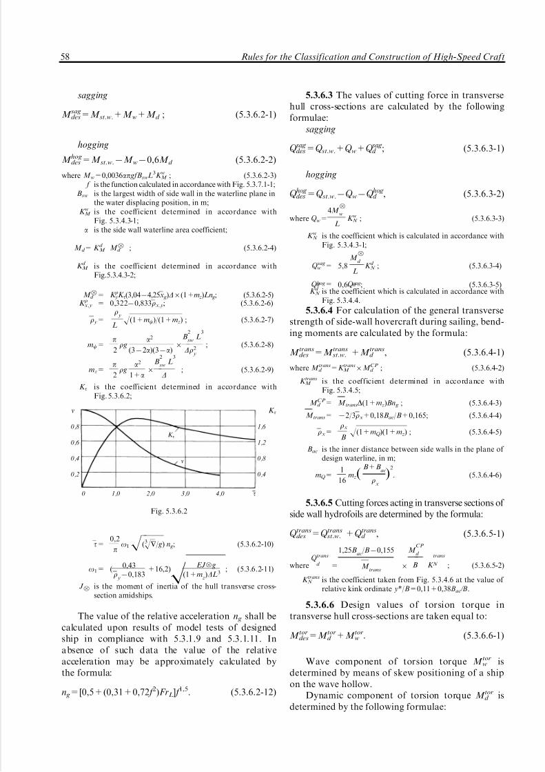
5/12/2018 High Speed Craft Rusa - slidepdf.com
http://slidepdf.com/reader/full/high-speed-craft-rusa 59/167
sagging
M sagdes=M st.w.+M w+M d ; (5.3.6.2-1)
hogging
M hogdes =M st.w.7M w70,6M d (5.3.6.2-2)
where M w=0,0036ap gfBswL3K wM ; (5.3.6.2-3) f is the function calculated in accordance with Fig. 5.3.7.1-1;
Bsw is the largest width of side wall in the waterline plane inthe water displacing position, in m;
K wM is the coefficient determined in accordance withFig. 5.3.4.3-1;
a is the side wall waterline area coefficient;
M d = K d M M :d ; (5.3.6.2-4)
K d M is the coefficient determined in accordance with
Fig.5.3.4.3-2;
M :d = K r yK t(3,0474,25x g)D6(1+mz)Ln g; (5.3.6.2-5)K rx,y = 0,32270,833rx,y; (5.3.6.2-6)
r y=r
y
LH(1+mc)/(1+mz) ; (5.3.6.2-7)
mc=p2r g
a2
(372a)(37a)6
B2
swL
3
Dr2 y
; (5.3.6.2-8)
mz=p2r g
a2
1+a6
B2
swL
3
D; (5.3.6.2-9)
K t is the coefficient determined in accordance withFig. 5.3.6.2;
t=0,2
po1H(3HH/ g) n g; (5.3.6.2-10)
o1= ( 0,43r
y70,183
+16,2)H EJ : g
(1+mz)DL3
; (5.3.6.2-11)
J : is the moment of inertia of the hull transverse cross-section amidships.
The value of the relative acceleration n g shall becalculated upon results of model tests of designedship in compliance with 5.3.1.9 and 5.3.1.11. Inabsence of such data the value of the relativeacceleration may be approximately calculated bythe formula:
n g=[0,5+(0,31+0,72 f 2)FrL] f 1,5. (5.3.6.2-12)
5.3.6.3 The values of cutting force in transversehull cross-sections are calculated by the followingformulae:
sagging
Q sag des=Q st.w.+Q w+Q
sag d ; (5.3.6.3-1)
hogging
Q hog des=Q st.w.7Q w7Q
hog d , (5.3.6.3-2)
where Q w=4M :
w
LK wN ; (5.3.6.3-3)
K wN is the coefficient which is calculated in accordance withFig. 5.3.4.3-1;
Q sagw = 5,8
M :
d
LK d
N ; (5.3.6.3-4)
Q hogd = 0,6Q sagd ; (5.3.6.3-5)K d
N is the coefficient which is calculated in accordance withFig. 5.3.4.4.
5.3.6.4 For calculation of the general transversestrength of side-wall hovercraft during sailing, bend-ing moments are calculated by the formula:
M transdes =M trans
st.w. +M transd , (5.3.6.4-1)
where M transd =K trans
M 6M CPd ; (5.3.6.4-2)
K transM is the coefficient determined in accordance with
Fig. 5.3.4.5;
M sr d = m transD(1+mz)Bn g ; (5.3.6.4-3)
M trans= 72/3rx+0,18Bac/B+0,165; (5.3.6.4-4)
rx=rx
BH(1+mQ )(1+mz) ; (5.3.6.4-5)
Bac is the inner distance between side walls in the plane of design waterline, in m;
mQ =1
16mz(
B+Bac
rx
)2
. (5.3.6.4-6)
5.3.6.5 Cutting forces acting in transverse sections of side wall hydrofoils are determined by the formula:
Q transdes =Q
transst.w. +Q
transd , (5.3.6.5-1)
whereQ trans
d =
1,25Bac
/B70,155
M trans
6
M CP
d
B K
trans
N ; (5.3.6.5-2)
K transN is the coefficient taken from Fig. 5.3.4.6 at the value of
relative kink ordinate y*/B=0,11+0,38 Bac /B.
5.3.6.6 Design values of torsion torque intransverse hull cross-sections are taken equal to:
M tordes=M tor
d +M torw . (5.3.6.6-1)
Wave component of torsion torque M torw is
determined by means of skew positioning of a shipon the wave hollow.
Dynamic component of torsion torque M tord is
determined by the following formulae:
n K t
0,8 1,6
K t0,6 1,2
0,4 0,8n
0,2 0,4
0 1,0 2,0 3,0 4,0 t
Fig. 5.3.6.2
58 Rules for the Classification and Construction of High-Speed Craft

5/12/2018 High Speed Craft Rusa - slidepdf.com
http://slidepdf.com/reader/full/high-speed-craft-rusa 60/167
within 0 to 2 sections
M tord =(749+100x750x2+f m)r, (5.3.6.6-2)
where x=17 j/20 is the number of section;
r=D(1+mz)n g yR
1+k; (5.3.6.6-3)
yR i s t h e p ar a me t er w hi c h i s t a ke n e q ua l t o0,25(B+Bac) for side-wall hovercraft;
k=0 motion of ship in the navigation regime;
f m= 7ax7bx2/2+c
pcospx7c/p; (5.3.6.6-4)
b= 6(2x g71); (5.3.6.6-5)
c= 43,7(4+b
127r2
y7x2 g); (5.3.6.6-6)
a= 17b/272c/p, (5.3.6.6-7)
within 2 to 4 sections
M tord =r(32780x+50x2+f m), (5.3.6.6-8)
within 4 to 20 sections
M tord =rf m. (5.3.6.6-9)
Wave component is calculated according to theformula:
M torw =0,32DB(3x g71)sinpx. (5.3.6.6-10)
5.3.7 Determination of design forces during motion
of hovercraft on the air cushion.5.3.7.1 Design value of the longitudinal bending
moment is determined in accordance with theformulae:
sagging
M sagdes=M st.w.+M w+M d 1+0,8M d 2 ; (5.3.7.1-1)
hogging
M hogdes =M st.w.7M w70,6M d 170,5M d 2 , (5.3.7.1-2)
where M w=0,0044a(1+2,2FrL70,33Fr3L)(0,874,9 Bsw/L)6
6(1,970,15Lac/ Bac)r gBswL3
fK wM ; (5.3.7.1-3)
f is the function which is determined in accordance withFig. 5.3.7.1-1;
K wM is the coefficient determined in accordance withFig. 5.3.4.3-1;
Bsw is the width of side wall in the waterline area planeduring motion on the air cushion, in m;
M d 1 is the dynamic bending moment caused by the blow of connecting bridge (bottom in the area of air cushion)against wave;
M d 2 is the dynamic bending moment caused by the blows of side walls against wave.
The value of the dynamic bending moment M d 1 isdetermined by the Formulae (5.3.6.2-4) and (5.3.6.2-5).
Meanwhile, the value of the vertical relative accelera-tion n g is calculated by the following formula:
n g=n1(17k g)+n2k g, (5.3.7.1-4)
where k g=3h2172h3
1 ; (5.3.7.1-5)
h1=f 76,5H ac/L;
n1=(0,33Fr2L+0,165FrL+0,05)(5,7h270,81h2+0,16)+0,42h2 ;
(5.3.7.1-6)
h2= 0,077L
3HD f ;
n2= [0,5+(0,34+0,72 f 2)FrL] f 1,5 . (5.3.7.1-7)
The value of the dynamic bending moment M d 2 isdetermined by the formula:
M d 2=0,052rB25L2
o1
r y
[0,42aH gL
(2,5FrL+1)+0,023V ]vK bM ,
(5.3.7.1-8)
where B5 is the side wall width in the waterline plane whichcorresponds to its immersion to the bilge in the area of the 5th section, in m;
v is the coefficient determined in accordance withFig. 5.3.6.2;
a=0,045(3,170,39FrD70,12Lac/Bac+0,02FrDLac/Bac6
6(1,1770,66r y/L)(2,575,8Bsw/B) fL; (5.3.7.1-9)
t=0,13o
1T 2
aH( g/L)(2,5FrL
+1); (5.3.7.1-10)
T 2 is the side wall draught immersed to the bilge in the areaof the 2nd section, in m.
5.3.7.2 Cutting forces acting in the transverse sectionsof side wall hovercraft are determined by the formulae:
Q sagdes=Q st.w.+
1L
[4M :w K wN +5,8M :d 1 K d N +3,2M :d 2 K wN ];
(5.3.7.2-1)
f
0,8
0,6
0,4
0,2
0 0,02 0,04 0,06 0,08 0,10 h3%/L
Fig. 5.3.7.1-1
Part II. Hull Structure and Strength 59

5/12/2018 High Speed Craft Rusa - slidepdf.com
http://slidepdf.com/reader/full/high-speed-craft-rusa 61/167
Q hogdes=Q st.w.7
1L
[4M :w K wN +3,5M :d 1 K d N +1,6M :d 2 K wN ].
(5.3.7.2-2)
5.3.7.3 While calculation of the general transversestrength of side wall hovercraft, calculations of transverse bending moments and cutting forces shallbe carried out in accordance with 5.3.6.4 and 5.3.6.5.While calculation of bending moment by the For-mula (5.3.6.4-3) the following value shall be taken forthe design relative acceleration:
n g=29M d 2r y/LtD(1+mz). (5.3.7.3)
5.3.7.4 Design values of torsion torque acting inthe transverse sections of side wall hovercrafts aredetermined in accordance with recommendations of 5.3.6.6. Parameter k is taken equal to 0,2 and value of
the relative acceleration is determined by the For-mula (5.3.7.3).
5.3.8 Calculation of loads which determine
strength of gliders.
5.3.8.1 Determination of design acceleration.Vertical acceleration A used during evaluation of
inertial forces transmitted by cargoes to the hullstructure are determined for two cases of ship bowslamming against head sea: strike against bow end (inthe area of the 3rd section) and strike amidships (tothe after end off the 3rd section) by the formula:
a/g= f h f V (1+ka)(4,8370,176ba+0,002b2
a)[0,67L/B:70,08(L/B:)270,35]
k p(1+mz),(5.3.8.1)
where f h=13{17exp[7(17h3%/ L72,9)2]}h3%/ L, if h3%/ L40,095;
f h=1,0, if h3%/ L>0,095;
f V =[0,96+0,48exp(2,5Frc72,5)]/[2,27+17,7exp(71,1FrD)]
Frc=0,514V/H gc ;
c=B4
:l 4
G/(
D/g
)7/3;
FrD=0,514V/H gH1/3 ;
n=0,5+0,8jV ;
jV =exp[70,75(FrD70,9)2] ;
ka=Ar2
yL(x7x g), but not less than 0;
A=0,539+0,311jV 7x g/L _ at strike against ship bow end;
A=ja[3,2770,205l7(0,70770,032l)FrD+(0,070770,003l)Fr2D ]r2 y L/B:,
but not less than 0 and not greater than 0,65xG/L _ at strike amidships;
ja=[1+(b:/3070,5)(70,071+0,067FrD70,002Fr2D )]kT ,
l is the value taken equal to equation L/B (or 5,0 depending whichever is greater);kT = 1,0 _ 1,0 for gliders with the usual hydrodynamic arrangement;
1,07 _ for the ships with the bottom air cavity;
r2 y=
I y(1+mc)
!L2(1+mz);
mz=1,3gB2: l G(17ba/180)
a2
1+a kz2
/D;
60 Rules for the Classification and Construction of High-Speed Craft

5/12/2018 High Speed Craft Rusa - slidepdf.com
http://slidepdf.com/reader/full/high-speed-craft-rusa 62/167
mc=0,39gB2: l G
3 (17ba/180)a2
(372a)(37a)kz2/I y ;
a=0,5(1+Btr/B:);
z=[170,425Z/(1+Z2)]Z/(1+Z2)0,5;
Z=3,4l G/(B:+Btr);
k= 1,0 _ for gliders without planing steps,0,85 _ for gliders with planing steps,0,5 _ for the ships with the bottom air cavity;
k p= (0,28570,737r y+0,047r)/(1+r) _ at strike against bow end0,36exp(70,168FrD) _ at strike amidships and the Froude number FrD<4,0,0,184 _ at strike amidships and the Froude number FrD54,0;
r= 0,8(17jV );ba is the deadrise angle of the transverse hull section (at wave strikes against the bow end the 3rd section is viewed, at wave strikes
amidships the distance of x=l G+AL from transom is viewed).
5.3.8.2 Loads determining general hull strength.5.3.8.2.1 Bending moments and cutting forces
acting in the transverse hull sections at sagging andhogging refer to the loads which determine generalhull strength of the glider. Distribution of bendingmoments and cutting forces over ship length is takenin accordance with 5.3.2.4.
5.3.8.2.2 The values of sagging and hoggingmoments amidships are determined by the formula:
M sag(hog)=M st.w.+kM DLaG/g, (5.3.8.2.2)
where M st.w. is the bending moment amidships at ship motion on
still water;aG is the value of the vertical acceleration a which iscalculated for the centre of ship gravity in accordancewith 5.3.8.1 (at the value of ka=0);
kM = k p at wave strike against bow end and sagging of hull.0,07 at wave strike amidships and hogging of hull.
5.3.8.2.3 Design values of cutting forces atsagging and hogging of hull is determined by thefollowing formula:
Q sag(hog)=4,5M sag(hog)/L . (5.3.8.2.3)
5.3.9 Loads determining strength of high speed
catamarans.
5.3.9.1 Determination of design accelerations.Design vertical accelerations a which are used for
assessment of pressure and forces transmitted bycargoes to the hull structures are determined by theformula:
a/g=[1,4+3,4FrLexp(72,7FrL)](1+2,5FrL)26
6 f H1+48(xM /L+0,075)2 +F , (5.3.9.1)
where g is the gravitational acceleration;xM is the abscissa of the point in question which is counted
off the midship section (negative if located to the end
bow from the midship);
f={17exp[7(17h3%/L72,9)2]}h3%/L,
if h3%/L50,095,
f=0,077, if h3%/L50,095;
F=(1+0,97l G/L
r72 y L
xM )n, but not less than 0;
l G is the distance between the centre of gravity and transom(from the aft perpendicular);
r72y =(J y g1+mc)/(DL21+mz);
J y is the central moment of inertia of ship mass abouttransverse axis;
D is the deep displacement;
mz=1,57r gB
2
hull La2
D(1+a);
mc=0,131rgB
2
hull L
Dr2
a2
(372a)(37a);
r is the density of sea water;Bhull is the hull width amidships in the plane of the
construction waterline;
a is the water-plane coefficient;
n=n1(17k g)+n2k g,
where k g=3h2172h3
1 ;
h1=13 f 76,5hcl /L;
n1=(0,33Fr2L +0,165FrL+0,05)6
6(5,7h2270,81h2+0,16)+0,42h2;
n2=[24+(16+5700 f 2)FrL] f 1,5 ;
Part II. Hull Structure and Strength 61

5/12/2018 High Speed Craft Rusa - slidepdf.com
http://slidepdf.com/reader/full/high-speed-craft-rusa 63/167
h2=L
3HHf ;
hcl is the hull clearance (distance between unperturbed watersurface and connecting bridge in the midship section).
5.3.9.2 Loads determining hull general strength.Bending moments and cutting forces as well as
torsion torques acting in the transverse and long-itudinal hull sections refer to the loads whichdetermine hull general strength.
These loads are determined by the formulae givenbelow or by test results of the elastic models equippedwith dynamometer sensors (see 5.3.1.10 and 5.3.1.11).
5.3.9.2.1 The value of the longitudinal bendingmoment in the transverse section of hull is deter-mined by the following formulae:
saggingM des
sag=M st.w.+M w+M d , t/m, (5.3.9.2.1-1)
hogging
M deshog=M st.w.7M w70,6M d , t/m, (5.3.9.2.1-2)
where M w=0,059arg(0,874,9BkL)(1+2FrL70,3Fr3L )BkL3 fkb
M , t/m;
M st.w. is the bending moment acting in the transverse section inquestion during ship motion on still water (positive atsagging);
f is the function which is determined in accordance with5.3.9.1;
kb
M is the coefficient characterising distribution of the wavecomponent of the moment along ship length and which isdetermined in accordance with Fig. 5.3.4.3-1;
M d is the dynamic component of the bending moment.Dynamic component of the bending moment is deter-mined by the formula:
M d =kr y(3,0474,25l G/L)D(1+mz)LnkqM , t/m,
where parameters mz and n are determined in accordance with5.3.9.1 and coefficient kq
M is in compliance withFig. 5.3.4.3-2.
kr yis the coefficient determined by the formula:
kr y=0,32270,833r y,
where parameter r y is determined according to 5.3.9.1.5.3.9.2.2 The values of the cutting force in the
transverse hull sections are calculated by the follow-ing formulae:
sagging
Q sagdes=Q st.w.+Q w+Q
sagd , t, (5.3.9.2.2-1)
hogging
Q hogdes =Q st.w.7Q w70,6Q hog
d , t, (5.3.9.2.2-2)
where Q w=4(M :w /L)kwN ; t,
Q sagd = 5,8(M :d /L)kd
N ; t.
M :w and M :d are the wave and dynamic components of thebending moment acting in the midship section of hull;
kwN and kd
N are the coefficients determined in accordance withFigs. 5.3.4.3-1 and 5.3.4.4.
5.3.9.2.3 Design values of the bending moment atsymmetrical transverse hull bending are calculated by
the following formulae:sagging
M sagtrans =M trans
st.w. +M trans , t/m; (5.3.9.2.3-1)
hogging
M hogtrans =M trans
st.w. 7M trans , t/m, (5.3.9.2.3-2)
where M transst.w. is the bending moment acting in the transverse hullsection during ship motion on still water (positive atsagging);
M trans=[0,12D(1+mz)Bn+0,0021r gB3L]ktransM , t/m,
w is the width amidships;mz and n are parameters determined by 5.3.9.1;
ktransM is the coefficient determined in accordance with
Fig. 5.3.4.5.
5.3.9.2.4 Cutting forces acting in longitudinal hullsections are determined by the formula:
Q transdes =(5,2M sag(hog)
trans /B) ktransN , t, (5.3.9.2.4)
where ktransN is the coefficient determined in accordance with
Fig. 5.3.4.6 if relative ordinate in taken
y*/B=0,11+0,38Bh/B ;
Bh is the horizontal hull clearance _ distance between hullsin the midship section measured in the plane of construction water line.
5.3.9.2.5 Design values of bending moment atskew-symmetrical bending of connecting structuresof catamaran are determined by the formula:
M astrans=N{[a1( y+1/2)+(b7a1)/4]+(a+
B7a1
2)6
6(2 y37 32
y71/2)}(17kc), t/m, (5.3.9.2.5)
where kc=0,25(17Bk/B)2{mz+B
k
B([15712cosp(0,57Bk/B)]6
6(rx70,288)+1)/[r2x (1+mc)]
};
N = 0,5Dn, T,
rx=1
BHJ x/D ;
Jx is the central moment of inertia of the ship's mass aboutlongitudinal axis;
y is the distance between section in question and long-itudinal centre plane;
BM is the distance between hulls at the level of connectingstructures.
Design value of the cutting force is taken equal to N.
5.3.9.2.6 Design values of torsion torques in thetransverse hull sections are taken equal to:
M tordes=DB[0,32(3l G71)sinpx+M d (x)], t/m, (5.3.9.2.6)
62 Rules for the Classification and Construction of High-Speed Craft

5/12/2018 High Speed Craft Rusa - slidepdf.com
http://slidepdf.com/reader/full/high-speed-craft-rusa 64/167
where x =17 j/20 ( j _ number of section);l G = l G/L is the relative distance between the gravity centre and
transom ( from the aft perpendicular).
Function M d (x) is determined by the following
dependencies:a) within 0 and 2 section
M d (x)=(749+100x750x2+ f m)r,
where r =0,25D(1+m z )( B+Bhor )n;
f m=7a x7bx2/2+cp
cospx7c/p;
b=6(2l G71);
c=43,7(4+b
127r2
y7l 2G );
a=17b/272c/p,
b) within 2 and 4 section
M d (x)=r(32780x+50x2+ f m),
c) within 4 and 20 section
M d (x)=rf m.
5.3.9.2.7 Transverse torsion torque (in the long-itudinal section of connecting structures by theinboard side) is determined by the following formula:
M tortrans =(0,1n+1,2 f )DL, t/m. (5.3.9.2.7)
5.3.10 Verification of the hydrofoil and glider
general strength.
5.3.10.1 General hull strength shall be verified:for permissible normal and tangential stresses;for marginal state.5.3.10.2 Design values of normal stresses in end
members of hull girder shall satisfy the followingconditions:
su=
auM
des/W
u4s per=n
ss0; (5.3.10.2-1)
sl =al M des/W l 4s per=nss0, (5.3.10.2-2)
where su and sl are the design stresses in the upper (superstructure)and lower (bottom) members of hull girder accordingly;
M des is the design bending moment at sagging and hoggingacting in the design section and determined in accor-dance with 5.3.3.3-5.3.3.9, 5.3.8.2.2;
W u and W l are the section moduluses for the upper and lowermembers of hull girder accordingly;
au and al are coefficients considering superstructures contribution tothe general hull bending which is taken equal to au=0,85and al =1,4 (in absence of regularly located windowopenings in superstructures coefficients au=al = 1);
ns is the safety margin taken in accordance with Fig. 5.2.8.
Distribution of normal stresses along height of hull section is taken linear.
5.3.10.3 If superstructure extends over practicallythe whole length of the ship hull, its sides coincide
with sides of the ship and they are weakened by alarge number of openings, normal stresses in hull sh
and awning (top) of superstructure ss as well asnormal sws and tangential tws stresses in the windowsoliving in the wall may be calculated by formulae:
sh=M des y/I 7T (1/F+ly/I ); (5.3.10.3-1)
ss=T/f ; (5.3.10.3-2)
sws=+abcT '/4i 0; tws=cT '/bt, (5.3.10.3-3)
where M des is the design bending moment (at sagging and hogging)
of the section in question, in kN/m; y is the distance between the member in question and
neutral axis of hull section, in m;I is the moment of inertia of the transverse hull section, in
m4;F is the area of the transverse hull section, in m2; f is the area of the transverse superstructure section, in m2;l is the distance between the centres of gravity lines of hull
sections from the centres of gravity lines of super-structure awning section, in m (Fig. 5.3.10.3);
a is the window height, in m (Fig.5.3.10.3);
b is the width of window soliving, in m;c is the spacing between window openings, in m;t is the thickness of window soliving, in m;
i 0 is the moment of inertia of the transverse section of window soliving, in m4;
T is the axial force acting along lines of centre of gravity of hull sections T h of the superstructure awning T s, kN,equal to:
T h= 7T N =T=T 0[lshl(l 7x)
shll $l
0
M x
M 0
shlxd x+lshlx
shll
$l
0
M h
M 0
shl(l 7x)d x]; (5.3.10.3-4)
T 0 is the force acting in the section in question if the super-structure awning shalltally involved in hull bending, in kN:
T 0=M 0lf
(F+f )I/F+fl 2 ; (5.3.10.3-5)
t, i 0ss l s
T s
a
l b l hc
M hM x T
h sh
x
Fig. 5.3.10.3
Part II. Hull Structure and Strength 63
5/12/2018 High Speed Craft Rusa - slidepdf.com
http://slidepdf.com/reader/full/high-speed-craft-rusa 65/167
M x= M h+Tl _ design bending moment which is varied alonghull length, in kN/m;
M h is the bending moment acting in the transverse hullsection, in kN/m;
l2= K E
(F+f Ff
+l 2/I ); (5.3.10.3-6)
E is the normal elasticity modulus, in kPa;
T '=K d; (5.3.10.3-7)
d is the shift of the centre of gravity of hull sections inrespect of the centre of gravity of the superstructureawning along axis x, in m;
d'=T/EF+T/Ef 7M hl/EI ; (5.3.10.3-8)
l is the length of superstructure, in m;K is the coefficient of hull and superstructure members
rigidity, in kN/m2;
K=1
1/K 0
+1/K h+1/K s; (5.3.10.3-9)
K 0 is the stiffness coefficient of superstructure side memberswhich are weakened by regular openings located at equalinterval from each other, in kN/m2;
K 0=E
ac(a2/12i 0
+2,6/bt); (5.3.10.3-10)
K h and K s are stiffness coefficients taking into account yielding of structure at the level of window openings as well asyielding to shift of the side of superstructure awning andside of hull:
K h=Eth
2,6l h(17thl h/2F ); (5.3.10.3-11)
K s=Ets
2,6l s(17tsl s/2F ); (5.3.10.3-12)
th and ts are mean thicknesses of plating adjoining window openings,hull and superstructure awning respectively, in m;
l h is the distance between the line of centre of gravity of hullsections and the lower edge of window openings, in m;
l s is the distance between the line of centre of gravity of hullsections and the upper edge of window openings, in m.
5.3.10.4 Design values of tangential stresses atsagging and hogging of hull shall comply with thefollowing conditions:
t=Q desS x
I xd4t per=0,3R p02, (5.3.10.4)
where Q des is the design value of cutting force calculated inaccordance with 5.3.3.3 _ 5.3.3.9;
S x is the moment of area of design transverse sectionrelative to zero line, in m3;
d is the total thickness of side and longitudinal bulkheads atthe level where tangential stresses are determined, in m.
Total design thickness of side and longitudinalbulkheads in absence of sufficient bulkhead plates
resistance to shear forces shall be calculated keepingdue note of reduction coefficient which is equal toratio of Euler stress tangents to design ones.
Side plating shall ensure safety margin of at least
1,5 if exposed to tangential stresses.
N o t e : if critical tangential stresses are determined with duenote of change of material modulus of elasticity, it is allowed totake t4tcr.
If resistance to tangential stresses is tested, onlytwo hull sections may be verified in the area of maximum cutting forces.
5.3.10.5 Verification of strength ultimate momentshall show that during both sagging and hogging of hull ratio of ultimate moment to the maximum designbending moment in the section under considerationshall comply with the following condition:
M ult/M des50,8/ns, (5.3.10.5-1)
where M ult=s0W 0 ; (5.3.10.5-2)W 0 is the minimum modulus hull section under considera-
tion, in m3 which is calculated keeping due note of reduction of area of members losing stiffness assumingthat in the far ends, the most distant from the zero line of hull members stresses equal to dangerous are acting;
ns is the safety margin taken in accordance with Fig. 5.2.8.
5.3.11 Calculation of hovercraft and high speed
catamarans hull strength at their longitudinal bending.
5.3.11.1 General hull strength during longitudinalbending shall be verified for the cases of sagging and
hogging of hull:permissible normal and tangential stresses if
design bending moments and cutting forces deter-mined for accepted design modes of motion areacting in accordance with 5.3.4 _ 5.3.7 and 5.3.9;
ultimate moments.5.3.11.2 Determination of normal and tangential
stresses acting in hull members during longitudinalbending as well as determination of ultimate momentis carried out in accordance with 5.3.8. Duringverification of general strength ultimate moment(see 5.2.9) the safety factor ns is taken equal to 2,0.
5.3.12 Calculation of hovercraft and high speedcatamarans hull strength at their transverse bending.
5.3.12.1 Determination of stresses during verifi-cation of the transverse hull strength is carried out bymeans of the finite element method or by means of the approximate method given below based on thebeam models of transverse bulkheads. This methodmay be used if B/D52 provided transverse bulkheadsare located across the whole width of hull. Transversebulkhead is calculated as a girder experiencingexposure of bending moment and cutting forces.General transverse bending moment and cuttingforce in the longitudinal section of hull are distrib-uted among separate bulkheads pro rata of theirbending/shear rigidity.
64 Rules for the Classification and Construction of High-Speed Craft

5/12/2018 High Speed Craft Rusa - slidepdf.com
http://slidepdf.com/reader/full/high-speed-craft-rusa 66/167
If the ship is landing on the bottom bearersretroaction is taken up by those members which arelocated immediately above bearers.
Bending/shear rigidity of some bulkheads is
determined by the formula:
I bs=1
l 2b/KEI b+1/hbdbG(5.3.12.1)
whereI b is the moment of inertia of the vertical section of
bulkhead with deck and bottom strakes, in m 4;l b is the length of bulkhead span, in m;hb is the average bulkhead height, in m;db is the average thickness of the bulkhead, in m;K is the coefficient taken from Table 5.3.12.1 in relation to
the bulkhead fixing on sides.
For the purposes of determination of the bulk-head moment of inertia adjoining face plates of bottom, platforms, decks shall be considered whichwidth is taken as the lesser value of those equal to 1/8length of the span or the distance between neighbour-ing bulkheads.
5.3.12.2 In absence of transverse bulkheads in themiddle (by width) part of hull, the calculation of thetransverse strength is carried out in relation to the levelof the bearing capacity of members supporting hull intransverse direction. If a twofold stability factor isensured for transverse members (ratio of the criticalcompressing load of girder to the force equal to themaximum transverse bending moment is greater orequal to two) then an assumption of the combinedaction of transverse members of superstructure deckand pontoon beams (beams and floors) making a singlehull girder shall be made for strength calculations.
If pontoon members (floors) safety factorscomply with conditions of 5.3.12.4-3, it is permissibleto reduce stability factor of transverse members of the superstructure deck (upper deck) to 1,2. In thiscase strength calculations shall be based on theassumption that beams and floors bend separately(not forming a single hull girder).
If an assumption of the combined action of beams and floors during transverse bending of hull isaccepted, calculation of the hull girder is carried outin a usual manner.
Compression stresses of beams and extensionstresses of floors found at an assumption of thecombined action of transverse members forming an
ideal girder during its transverse sagging shall beadded to the additional normal stresses conditionedby bending of transverse members among long-itudinal bulkheads which was caused by shear forces
acting in hull.Additional bending moments in some beams and
floors are distributed in proportion to their bending/shear rigidity evaluated by the parameter:
lts=1
l 2ts /(2EI ts)+1/(GF ts), (5.3.12.2-1)
where lts is the distance among longitudinal bulkheads;F ts and I ts is the web cross-sectional area of transverse member and
moment of inertia of its transverse section.
Total bending moment distributed among sepa-rate beams is determined by the formula:
M E =0,33Q transel l ts , (5.3.12.2-2)
where Q transel is the maximum cutting force in longitudinal hull
sections determined in accordance with 5.3.4.4, 5.3.4.6,5.3.4.8, 5.3.6.3, 5.3.6.5, 5.3.7.3 and 5.3.9.
Determination of the normal and tangentialstresses in the transverse member components iscarried out by the formulae:
s=M des y/I ; (5.3.12.2-3)
t=Q s/I d, (5.3.12.2-4)
where M des is the design bending moment in the section under
consideration;I is the moment of inertia of the section area calculated
with due account of reduction of members; y is the distance between the member under consideration
from the neutral axis of section;Q is the design cutting force acting in section;s is the static moment relative to neutral axis of the part of
section area lying above axis under consideration;d is the total thickness of section sides at the horizontal
level under consideration.
If transverse member represents symmetrical flatgirder frame, normal stresses in its strakes aredetermined by the formula:
s=M des/ahF gf , (5.3.12.2-5)
where F gf is the girder flange area;ah is the distance between strakes (height of girder).
Cutting forces are balanced in girder joint byforces in diagonal members and posts which aredetermined by methods of girder calculation. Normalstresses in diagonal members are calculated as a ratioof the determined axis force to the area of transversesection of respective component.
5.3.12.3 If there are transverse bulkheads amid-ships critical strength of hull shall be checked againstthe following conditions:
Conditions of transverse members ends fixing K
Simple support
Fixed embedment
D D 24
96
T a b l e 5.3.12.1
Part II. Hull Structure and Strength 65

5/12/2018 High Speed Craft Rusa - slidepdf.com
http://slidepdf.com/reader/full/high-speed-craft-rusa 67/167
M transhs /M trans
el 52;
(5.3.12.3)Q
transult /Q
transel 51,5,
where M transhs and Q
transel is the maximum value of total bending
moment and cutting force in longitudinal section of girder-bulkhead for the mode of operation underconsideration;
M transhs = s0W trans
k is the ultimate bending moment of the girder-bulkhead;
Q transult = 0,5Obs0,2 is the ultimate cutting force for the transverse
bulkhead under consideration;W trans
k is the modulus of section of the girder-bulkheadcalculated on the assumption that stresses acting in theend fibres are equal to dangerous s0 calculated inaccordance with 5.2.3;
Ob is the area of the transverse bulkhead (by vertical plane).
5.3.12.4 In absence of transverse bulkheads
amidships and use of an assumption of the isolatedaction of beams and floors at the calculation of transverse strength (see 5.3.12.2), the strength of thelatter shall be tested by the value of the ultimatemoment and ultimate cutting force determined by theformulae:
M F hs=soW F
e ; (5.3.12.4-1)
Q F hs=0,5OF R p02, (5.3.12.4-2)
where W F e is the modulus of the floor section calculated on theassumption that stresses acting in the end fibres are equalto dangerous ones (assigned in accordance with 5.2).
OF is the area of the floor web section.
In this case the following conditions shall befulfilled:
M F hs/M F 52 ; Q
F hs/Q F 51,5, (5.3.12.4-3)
where M F and Q F is the maximum total bending moment andcutting force in the transverse floor sections determinedwith due account of the moments evolving during generaltransverse hull bending, local loads (see 5.4.6.5) condi-tioned by cargo (transported equipment, fuel, water, etc.)and additional bending moments determined in accor-dance with 5.3.10.2.
In absence of transverse bulkheads amidshipsand use of an assumption of the combined action of beams and floors (see 5.3.12.2), the hull strength shallbe verified for the ultimate moment in compliancewith condition (5.3.12.3) and verification of the floorcritical strength by condition (5.3.12.4-3). For thesepurposes only the component conditioned by cargo(equipment, fuel, water, etc.) and additional bendingmoment determined in accordance with 5.3.12.2 areincluded into the design value of the total bendingmoment.
5.3.12.5 During calculation of structure of thehigh speed catamarans in case of absence of transverse bulkheads in the middle (by width) partof hull bounded from below and from above by
connecting structures, it is necessary to assess stressescaused by both symmetrical and skew-symmetricalbending of hull.
General transverse bending moment at skew-
symmetrical bending (see 5.3.9.2.5) is distributedamong separate transverse girders (floors and beams)of connecting structures in proportion to theirbending and shear rigidity.
Stresses arising at the skew-symmetrical bendingof the transverse girder components shall be added tothe stresses conditioned by symmetrical bending. Forthese purposes evaluation of symmetrical bendingstresses is carried out following the usual scheme, hullgirder consisting of the components of connectingstructures. Values of symmetrical bending momentand cutting forces are determined by totalling of
stresses equal to 70 per cent of values calculated inaccordance with 5.3.9.2.3 and 5.3.9.2.4.5.3.13 Calculation of the hovercraft and high speed
catamaran hull torsional strength.
5.3.13.1 If there are transverse bulkheads in hullwhich extend across the whole width of hull,transverse section is considered rigid in its planeduring torsion. General torsion torque acting in thesection is distributed among single member contours(the contour means a component of transversesection of hull bound by longitudinal bulkheads orby longitudinal bulkheads and sides, deck, bottom)which comprise transverse section in proportion to
the torsional rigidity determined by the formula:
C i =o2c/S
n
c=1
(l c/dc), (5.3.13.1-1)
where l c is the length of the contour wall, in m;dc is the thickness of the contour wall, in m;
oc is the double area bound by c contour, in m2,(Fig. 5.3.13.1);
n is the number of contour walls.
l 2
d2
l 1d
1
o/2 d3l 3
d
l 4
Fig. 5.3.13.1
66 Rules for the Classification and Construction of High-Speed Craft

5/12/2018 High Speed Craft Rusa - slidepdf.com
http://slidepdf.com/reader/full/high-speed-craft-rusa 68/167
Tangential stresses caused by torsion in the walls of each contour section are determined by the formula:
ti =M i /oi di , (5.3.13.1-2)
where M i is the share of the torsion torque applied to the i -thcontour, in kN´m.
Total of tangential stresses in the common wall of the two neighbouring contours are calculated as thedifference of stresses in this wall caused by eachcontour.
5.3.13.2 Additional normal and tangential stres-ses in transverse members shall be determined for theships with the middle cargo compartment wheretransverse bulkheads are absent over the whole orpart of its length.
Additional tangential stresses on the cargo deck
and bottom are calculated by the formula:tdb=+Ghd {a[
32
1l/2
732
y2
(l/2)3]+b 1l/2
}, (5.3.13.2-1)
where hd is the height of cargo deck above the main deck, in m;l is the width of cargo compartment (Fig. 5.3.13.2), in m.
Mark (+) refers to bottom,Mark (7) refers to cargo deck.
Parametres a and b are determined by the formulas:
a=F (B7D)B27AD
;
b=F (B7A)B27AD
;
A=C gLc+ E G D g
L3
c3 ;
B=C ZLc+E G
D gZ
L3
c
3;
D=C ZLc+E G
DZ
L3
c
3;
F=O/GLc ;
O is the torsion torque diagram on the section of Lc , in kN´m2;Lc is the length of cargo compartment determined in
accordance with Fig 5.3.13.2, in m;C g, C Z, D g, DZ, D gZ are rigidity parametres determined by the
formulae:
C g=4,8h
2
d
l (dd 7db) ;
C Z=4h
2
d
l (dd +db) ;
D g=(I F /bF +I d/bd)6
(l/2)3 ;
DZ=I dbd
6(l/2)3+
GE
4tF hd
lbF
;
D gZ=I dbF
6(l/2)3 ;
I F and I d are floor and beam moments of inertia, in m4;bF and bd is the spacing between floors and beams, in m;
tF is the thickness of floor wall, in m;dd and db is the average thickness of cargo deck and bottom, in m.
Normal stresses in floors and beams caused by
general torsion of hull are calculated by the formulas:
sF =7E ax12
l 2 zF ; (5.3.13.2-2)
sd=7E (a+b)x12
l 2 zd,
where zF and zd are distances of the floor or beam point underconsideration from the neutral axis of the designmember, in m;
x is the section abscissa (Fig. 5.3.13.2), in m.
Tangential stresses in the floor plate are calcu-lated by the formula:
tF =G
bx
1
l/2. (5.3.13.2-3)
Maximum stresses sF , sd, tF are reached insections at x=Lc.
5.3.13.3 During calculation of high speed cata-marans in absence of transverse bulkheads in themiddle (by width) part of hull stresses evolving at theskew-symmetrical bending of hull transversely shallbe added to stresses caused by twisting and localbending of transverse beams (floors) of the connect-ing bridge. The value of the skew-symmetricalbending moment and cutting force is determined inaccordance with 5.3.9.2.5, while the value of thetorsion torque is taken equal to 80 per cent of designvalue calculated according to 5.3.9.2.6.
Z
Lc
A
0 x
Part of hull Awith transverse bulkheads
B
Z Lc
0 x
B
Hull without transverse bulkheads
a-a B-B
Z Z
c.t. 0 xc.t. 0 x hd dtrans
hd
dtrans
l db
dbl
Fig. 5.3.13.2
Part II. Hull Structure and Strength 67

5/12/2018 High Speed Craft Rusa - slidepdf.com
http://slidepdf.com/reader/full/high-speed-craft-rusa 69/167
Pressure on transverse girders is taken equal to60 per cent of the value calculated according to 5.4.5.
Permissible stresses during verification of hullstrength for the combined action of the skew-
symmetrical bending and torsion are taken inaccordance with 5.2.
5.4 Calculation of local strength.
5.4.1 General.
5.4.1.1 The following conditions shall be con-sidered during calculation of grillage, plate frame,framing:
.1 spans between girders constituting plate frameare taken for the distance between intersections of theneutral axis of respective girders;
.2 it is allowed not to consider variability of thegirder sections formed by brackets if brackets do not
exceed 0,1 of the girder span; presence of spans shallbe considered in this case for determination of moment of girder resistance on bearers; if bracketsexceed 0,1 girder span, it is allowed to considerinfluence of variability of the moment of inertia onbending moments;
.3 curvilinear girders with sagging of less than10 per cent of span are considered straight.
5.4.1.2 Geometrical components of girder sectionshall be determined with due consideration of effective flange whose width depends on variousfactors.
5.4.1.2.1 During bending calculation the width of
effective flange is taken equal to the distance betweensame girders.
5.4.1.2.2 During rigidity calculation the width of effective flange is taken:
at determination of the girder section area _
equal to distance between same girders;at determination of the moment of inertia of the
transverse girder section equal to:
C=a2
(1+j), (5.4.1.2.2)
where C is the width of effective flange, in m;a is the distance between same girders, in m;
j=se/ss .
N o t e : i f se>ss take j=1.
5.4.1.2.3 For bending calculation _ for thetransverse girders lying above longitudinal stiffeners(floating framing system), width of effective flange istaken equal to:
if connecting plates are mounted at every secondstiffener _ 80 per cent of the normal flange acceptedin 5.4.1.2.2;
if connecting plates are mounted at every thirdstiffener _ 60 per cent of the normal flange acceptedin 5.4.1.2.2;
if there are connecting plates mounted only insupporting section _ 1/32 of the girder span.
Stresses on the effective flange shall be deter-mined by the formula:
sE.F.=s*E.F.6l/24C , (5.4.1.2.3)
where sE.F. are stresses in effective flange, in kPa;s*
E.F.. are stresses in effective flange, calculated on theassumption that plating of 1/32 is included into thegirder section, in kPa;
l is the girder span, in m;C is the width of the normal effective flange of the girder under
consideration taken in accordance with 5.4.1.2.2, in m.
If details connecting transverse girders with platingare absent or plating has lost rigidity between connect-ing details effective flange is not taken into account.
5.4.1.2.4 In all cases the width of effective flangeshall not exceed 1/6 design span _ for stiffeners and1/12 girder length (grillage) for reinforced girders.
5.4.1.2.5
Longitudinal stiffeners located on thestrake width form a part of effective flange of stringers and carlings.
5.4.1.3 Calculation of shell plates and deckplating side walls as well as bulkhead and super-structure plating shall be carried out on the assump-tion of their rigid fixing in the supporting contour. If the ratio of the supporting contour sides is greaterthan 2,5 it is allowed to treat the plate as the onebending by cylindrical surface.
Issue of consideration of membrane stress in theplate shall be resolved in each particular case. If ratioof the smaller side of plate to its thickness is equal to
or less than 60, plates shall be usually treated asabsolutely rigid.
5.4.1.4 Strength and rigidity (with safety factor of at least 1,5) of supporting structures (decks, plat-forms, bulkheads etc.) against maximum loads whichare transmitted to them from the said grillage shall betested during strength verification of girders of bottom and side grillage.
5.4.1.5 Local rigidity of framing girders tonormal and tangential stresses with safety factor of at least 1,5 shall be verified during calculation of grillage strength.
5.4.1.6 Calculation of transverse bulkheads fram-ing girders to the emergency flooding is permitted forperformance following method of ultimate load withthe safety factor of at least 1,5.
5.4.2 Loads determining strength of the hydrofoil
bottom structures.
5.4.2.1 Strength of bottom structures shall betested for the impact of external forces arising duringship motion on foils and during entrance to the foilmode in conditions of the design (stated in theperformance specification) seaway and speeds corre-sponding to those regimes as well as exposure toemergency flooding.
5.4.2.2 Strength of bottom components: plates,stiffeners and frame parts between stringers shall be
68 Rules for the Classification and Construction of High-Speed Craft
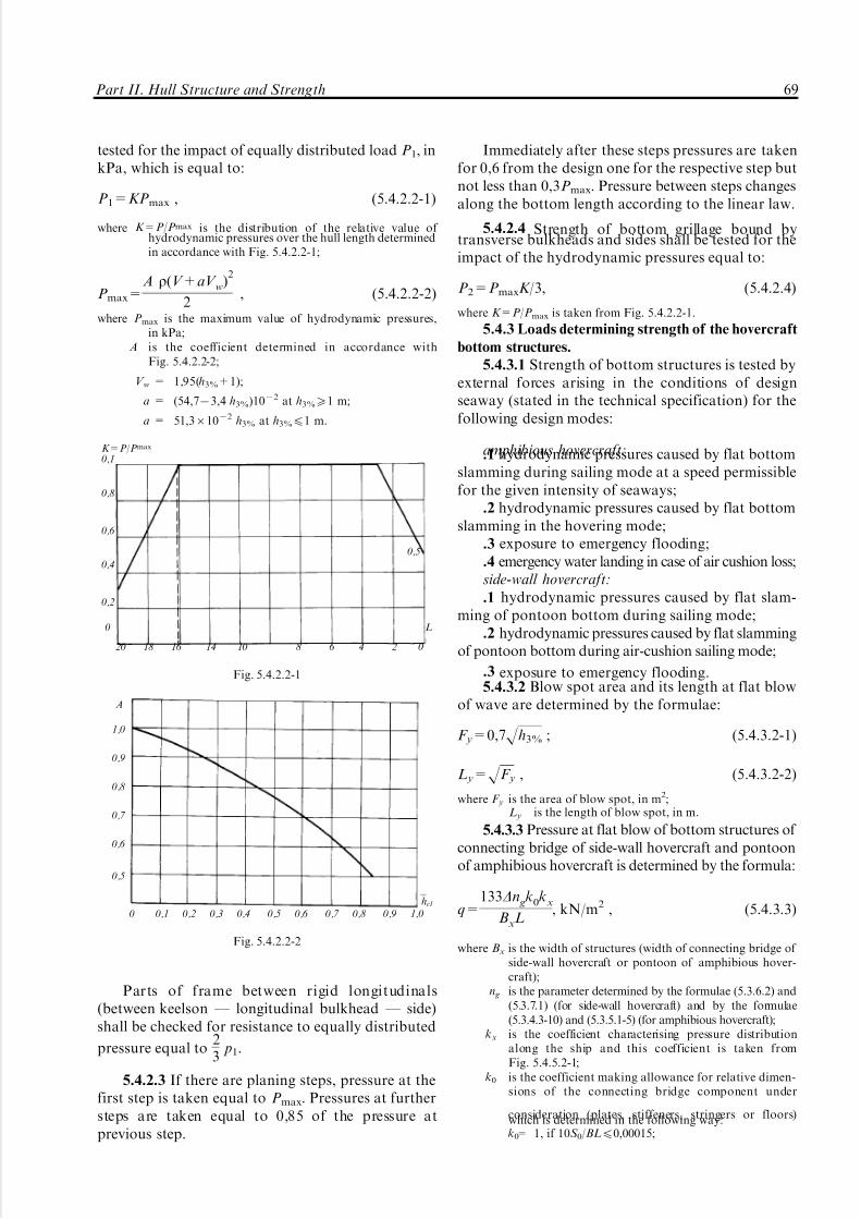
5/12/2018 High Speed Craft Rusa - slidepdf.com
http://slidepdf.com/reader/full/high-speed-craft-rusa 70/167
tested for the impact of equally distributed load P1, inkPa, which is equal to:
P1=KPmax , (5.4.2.2-1)
where K=P/Pmax is the distribution of the relative value of hydrodynamic pressures over the hull length determinedin accordance with Fig. 5.4.2.2-1;
Pmax=A r(V+aV w)
2
2, (5.4.2.2-2)
where Pmax is the maximum value of hydrodynamic pressures,in kPa;
A is the coefficient determined in accordance withFig. 5.4.2.2-2;
V w = 1,95(h3%+1);
a = (54,773,4 h3%)1072 at h3%51 m;
a = 51,361072 h3% at h3%41 m.
Parts of frame between rigid longitudinals(between keelson _ longitudinal bulkhead _ side)shall be checked for resistance to equally distributed
pressure equal to23
p1.
5.4.2.3 If there are planing steps, pressure at thefirst step is taken equal to Pmax. Pressures at furthersteps are taken equal to 0,85 of the pressure atprevious step.
Immediately after these steps pressures are takenfor 0,6 from the design one for the respective step butnot less than 0,3Pmax. Pressure between steps changesalong the bottom length according to the linear law.
5.4.2.4 Strength of bottom grillage bound bytransverse bulkheads and sides shall be tested for theimpact of the hydrodynamic pressures equal to:
P2=PmaxK/3, (5.4.2.4)
where K=P/Pmax is taken from Fig. 5.4.2.2-1.
5.4.3 Loads determining strength of the hovercraft
bottom structures.
5.4.3.1 Strength of bottom structures is tested byexternal forces arising in the conditions of designseaway (stated in the technical specification) for thefollowing design modes:
amphibious hovercraft:.1 hydrodynamic pressures caused by flat bottomslamming during sailing mode at a speed permissiblefor the given intensity of seaways;
.2 hydrodynamic pressures caused by flat bottomslamming in the hovering mode;
.3 exposure to emergency flooding;
.4 emergency water landing in case of air cushion loss;side-wall hovercraft:
.1 hydrodynamic pressures caused by flat slam-ming of pontoon bottom during sailing mode;
.2 hydrodynamic pressures caused by flat slammingof pontoon bottom during air-cushion sailing mode;
.3 exposure to emergency flooding.5.4.3.2 Blow spot area and its length at flat blow
of wave are determined by the formulae:
F y=0,7Hh3% ; (5.4.3.2-1)
L y=HF y , (5.4.3.2-2)
where F y is the area of blow spot, in m2;L y is the length of blow spot, in m.
5.4.3.3 Pressure at flat blow of bottom structures of connecting bridge of side-wall hovercraft and pontoonof amphibious hovercraft is determined by the formula:
q=133Dn gk
0kx
BxL, kN/m2 , (5.4.3.3)
where Bx is the width of structures (width of connecting bridge of side-wall hovercraft or pontoon of amphibious hover-craft);
n g is the parameter determined by the formulae (5.3.6.2) and(5.3.7.1) (for side-wall hovercraft) and by the formulae(5.3.4.3-10) and (5.3.5.1-5) (for amphibious hovercraft);
kx is the coefficient characterising pressure distributionalong the ship and this coefficient is taken fromFig. 5.4.5.2-1;
k0 is the coefficient making allowance for relative dimen-sions of the connecting bridge component under
consideration (plates, stiffeners, stringers or floors)which is determined in the following way:k0= 1, if 10S 0/BL40,00015;
K=P/Pmax
0,1
0,8
0,6
0,5
0,4
0,2
0 L
20 18 16 14 10 8 6 4 2 0
Fig. 5.4.2.2-1
a
1,0
0,9
0,8
0,7
0,6
0,5
hcl
0 0,1 0,2 0,3 0,4 0,5 0,6 0,7 0,8 0,9 1,0
Fig. 5.4.2.2-2
Part II. Hull Structure and Strength 69

5/12/2018 High Speed Craft Rusa - slidepdf.com
http://slidepdf.com/reader/full/high-speed-craft-rusa 71/167
k0= exp[71,9(10S o/BL70,00015)0,2],
if 10S 0/BL>0,00015,but not less than 0,3,
where S 0 is the area supported by a component; for plates thesupported area is taken equal to product of distance
between stiffeners (spacing) by the value equal to the lengthof the largest plate or triple spacing (whichever is less).
5.4.3.4 Strength of bottom plating shall be testedby pressure determined by the Formula (5.4.3.3) forthe sailing on air cushion and for sailing in water-displacing mode keeping due note of 5.4.3.2.
5.4.3.5 Strength of longitudinal stiffeners shall betested by the load of bq intensity where q isdetermined in accordance with 5.4.3.2 by theFormula (5.4.3.3).
5.4.3.6 Strength of bottom grillage shall be testedby pressure determined from 5.4.3.3, which acts on
the spot (area F ) which is located by the most adversemanner for the strength of grillage while:F=P/q is the area of application of pressure to
the grillage, in m2;P=Dn g(1+mz) is the grillage impact force, in t;mz is the parameter determined by the formulae
(5.3.4.3-8) (for amphibious hovercraft) or (5.3.6.2-9)(for side-wall hovercraft);
n g is the hull overload in the gravity centre atwave impact in the grillage under consideration,determined upon testing of models or similar ships.In absence of such data at early design stages it mightbe determined on the basis of approximated depen-
dencies 5.3.4.3-10 (hovercraft _ sailing), 5.3.5.1-5(hovercraft _ during hovering), 5.3.6.2-12 (hover-craft _ sailing) and 5.3.7.1 ( hovercraft _ on aircushion).
5.4.3.7 Loads arising as a result of the emergencyflooding are determined by the formula:
P1=10(h1 + H ), (5.4.3.7)
where P1 is the pressure of emergency flooding on bottom, in kPa;h1 is the value of emergency flooding taken from
Table 5.4.3.7;H is the spacing between pontoon deck plating and bottom
plating, in m.
5.4.3.8 In case of emergency water landing (if anair cushion has been deteriorated) strength of bottomgrillage _ plates, stiffeners and parts of websbetween stringers _ shall be tested for the impactof equally distributed load, in kPa, which value istaken equal to:
Pmax=rV 2/2 . (5.4.3.8-1)
Strength of bottom grillage bound by transversebulkheads and sides shall be tested for the impact of hydrodynamic pressures, in kPa, equal to:
P gr=Pmax/3. (5.4.3.8-2)N o t e : in this case it is necessary to ensure strength and
stability of web framing (stringers, frames). The value of permissible stresses s per=s0 .
5.4.4 Loads determining strength of bottom
structures of the glider.
5.4.4.1 Hydrodynamic pressures on bottomgrillage and their components are determined by thefollowing formula:
p=K pM sag
B3L2 j1j2j3 , kN/m2, (5.4.4.1)
where B3 is the width of hull in the area of bilge in the section of the 3rd frame;K p is the parameter which is taken equal to 280 for the
cavity vault of the ship with an air cavity in the bottomand equal to 370 for other bottom structures of gliders;
j1= 0,4+1,2x/L with x/L<0,51,0 with 0,54x/L40,853,5573x/L with x/L>0,85;
j2= (707ba)/(707b:);j3= 0,4670,35(U 0,7571,7)/(U 0,75+1,7) , but not less than
0,48 _ for plates and stiffeners;0,35 _ for floors and stringers;
U = 200s/(BtrL),where s is the area of load application.
Area s represents the area of grillage; for the
floors and stringers _ product of distance betweengirders by their length; for the plates and stiffeners s
is taken equal to product distance between stiffeners(spacing) by the value equal to the length of thelargest plate side or triple spacing (whichever is less).
5.4.5 Loads determining local strength of high
speed catamarans.
5.4.5.1 Local strength of structures is tested byexternal forces arising in the conditions of designseaway for the following design cases:
impact (slamming) pressures acting in adverseoperational conditions (with an exception of the
outer side structures);wave (static) pressures acting in adverse operational
conditions (with an exception of connecting bridge);impact of emergency flooding determined in
accordance with 5.4.6.5.4.5.2 Impact pressures on structures of the
connecting bridge are determined by the formula:
Pcs=133Dnk
0kx
BcsL, kN/m2 , (5.4.5.2)
where Bcs is the width of the connecting bridge (distance betweenhulls at the level of the connecting bridge);
n is the parameter determined by formula 5.3.9.1;
kx is the coefficient characterising distribution of pressurealong ship length and determined in accordance withFig.5.4.5.2;
Section " Meters of lift (m)
03
6 _ 10
1,501,000,50
T a b l e 5.4.3.7
70 Rules for the Classification and Construction of High-Speed Craft

5/12/2018 High Speed Craft Rusa - slidepdf.com
http://slidepdf.com/reader/full/high-speed-craft-rusa 72/167
k0 is the coefficient taking into account relative dimensionsof the connecting bridge component under consideration(plates, stiffeners, stringers or floors) which is determinedin the following manner:
k0= 1, if 10S o/BL40,00015;
k0= exp[71,9(10S 0/BL70,00015)0,2],
if 10S 0/BL>0,00015,but not less than 0,3.
N o t e: Here S 0 is the area supported by the component; forthe plates the supported area is taken equal to the product of distance between stiffeners (spacing) and the value of the largestplate side or triple spacing (whichever is less).
5.4.5.3 Impact pressures on the hull bottomstructures are determined by the formula:
Pi =(56Fr
2
L+28FrL+70)h
BhLkxkb
o ksh , kN/m2 , (5.4.5.3)
where Bh is the hull width amidships measured on the waterlinecorresponding to immersion of hull to the bilge;
h is the parameter calculated in accordance with 5.3.9.1;ksh is the coefficient considering bottom shape;
ksh= 1 _ for components of side structures;ksh= 0,158/tgb _ for components of side structures;
b is the parameter which is taken equal to the angle of riseof bottom _ not less than 108 but not greater than 308;
kb0 is the reduction coefficient taken equal to:kb
0 = 0,4670,35(U 0,7571,7)/(U 0,75+1,7);U=286S oT/D ;
S 0 is the the area supported by the component;T is the ship draught on still water but not less than:
0,48 _ for plates and stiffeners;0,35 _ for floors and stringers;
kx is the coefficient characterising distribution of pressurealong ship which is taken from Fig. 5.4.5.2.
5.4.5.4 Impact pressures on the inner sidestructures (Fig. 5.4.5.4) are taken distributed inaccordance with the linear law from the upper pointin which pressure is determined in accordance with5.4.5.2, to the lower bilge point in which pressure is inaccordance with 5.4.5.8.
5.4.5.5 The maximum wave pressures are deemeddistributed over the hull surface in accordance withFig. 5.4.5.4.
5.4.5.6 The maximum wave pressures on the levelof design water line is determined by the formula:
Pwl w=0,81 fLr g{a(x)+0,25exp[7(0,22HL/h0,4
3%71,97)2]}, kN/m2,
(5.4.5.6-1)
where a(x)={aexp[78x2+10x+3,29)]71,05}exp(72,9FrL)++aexp[7(1,9674,9x)exp(72,9FrL)]+1,05,
but not less than 0,62;
x=x/L is the relative abscissa of the point counted from midshipsection:
a= (3,170,39FrD70,12L/Bhor+0,02FrDL/Bhor)6
6(1,170,63r y)(1,072,5Bhull /B);
FrD=V/H gH1/3 ;
Bhor is the distance between hulls amidships measured alongthe design waterline;
r y is the dimensionless central radius of the inertia of shipmass determined in accordance with 5.3.9.1.
The maximum wave pressures above the level of design waterline:
Pw
=kw
(Pwl
w 7rgz
i ), kN/m2 , (5.4.5.6-2)
where zi is the distance between the point under consideration andthe level of design waterline;
kw= 1 _ for freeboard (inner and outer sides);0,96 _ determination of design pressures acting on thestructural components of open decks (plates, stiffeners);0,67 _ determination of design pressure acting onbeams, stringers and grillage of open decks.
5.4.5.7 The maximum wave pressure acting onbottom structures of hulls are determined by theformula:
PbB=r g[0,81 fLa(x)km(x)+zb], kN/m2 , (5.4.5.7)
where zb is the distance between point on bottom and level of
design waterline;
k x
0,8
1
0,6
0,42
0,2
0
20 18 16 14 12 10 8 6 4 2 0
1 _ connecting bridge2 _ hull bottom
Fig. 5.4.5.2
Pw
Pcs
Pwl w
PbB
PbB
Fig. 5.4.5.4Distribution of design pressures
by the contour of the transverse section:
Wave pressuresBlow pressures
Part II. Hull Structure and Strength 71
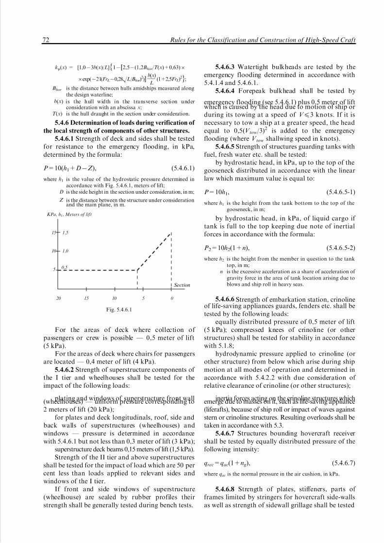
5/12/2018 High Speed Craft Rusa - slidepdf.com
http://slidepdf.com/reader/full/high-speed-craft-rusa 73/167
km(x) = [1,073b(x)/L]{17[2,57(1,2Bhor/T (x)+0,63)6
6exp(721(FrL70,28HL/Bhor)2)]
b(x)
L(1+2,5FrL)2};
Bhor is the distance between hulls amidships measured alongthe design waterline;
b(x) is the hull width in the transverse section underconsideration with an abscissa x;
T (x) is the hull draught in the section under consideration.
5.4.6 Determination of loads during verification of
the local strength of components of other structures.
5.4.6.1 Strength of deck and sides shall be testedfor resistance to the emergency flooding, in kPa,determined by the formula:
P=10(h1+D7Z ), (5.4.6.1)
where h1 is the value of the hydrostatic pressure determined inaccordance with Fig. 5.4.6.1, meters of lift;
D is the side height in the section under consideration, in m;
Z is the distance between the structure under considerationand the main plane, in m.
For the areas of deck where collection of passengers or crew is possible _ 0,5 meter of lift(5 kPa).
For the areas of deck where chairs for passengersare located _ 0,4 meter of lift (4 kPa).
5.4.6.2 Strength of superstructure components of the I tier and wheelhouses shall be tested for theimpact of the following loads:
plating and windows of superstructure front wall(wheelhouses) _ uniform pressure corresponding to2 meters of lift (20 kPa);
for plates and deck longitudinals, roof, side andback walls of superstructures (wheelhouses) andwindows _ pressure is determined in accordancewith 5.4.6.1 but not less than 0,3 meter of lift (3 kPa);
superstructure deck beams 0,15 meters of lift (1,5 kPa).Strength of the II tier and above superstructures
shall be tested for the impact of load which are 50 percent less than loads applied to relevant sides andwindows of the I tier.
If front and side windows of superstructure(wheelhouse) are sealed by rubber profiles theirstrength shall be generally tested during bench tests.
5.4.6.3 Watertight bulkheads are tested by theemergency flooding determined in accordance with5.4.1.4 and 5.4.6.1.
5.4.6.4 Forepeak bulkhead shall be tested by
emergency flooding (see 5.4.6.1) plus 0,5 meter of liftwhich is caused by the head due to motion of ship orduring its towing at a speed of V 43 knots. If it isnecessary to tow a ship at a greater speed, the headequal to 0,5(V tow/3)2 is added to the emergencyflooding (where V tow shallwing speed in knots).
5.4.6.5 Strength of structures guarding tanks withfuel, fresh water etc. shall be tested:
by hydrostatic head, in kPa, up to the top of thegooseneck distributed in accordance with the linearlaw which maximum value is equal to:
P=10h1, (5.4.6.5-1)
where h1 is the height from the tank bottom to the top of thegooseneck, in m;
by hydrostatic head, in kPa, of liquid cargo if tank is full to the top keeping due note of inertialforces in accordance with the formula:
P2=10h2(1+n), (5.4.6.5-2)
where h2 is the height from the member in question to the tanktop, in m;
n is the excessive acceleration as a share of acceleration of gravity force in the area of tank location arising due toblows and ship roll in heavy seas.
5.4.6.6 Strength of embarkation station, crinolineof life-saving appliances guards, fenders etc. shall betested by the following loads:
equally distributed pressure of 0,5 meter of lift(5 kPa); compressed knees of crinoline (or otherstructures) shall be tested for stability in accordancewith 5.1.8;
hydrodynamic pressure applied to crinoline (orother structure) from below which arise during shipmotion at all modes of operation and determined inaccordance with 5.4.2.2 with due consideration of relative clearance of crinoline (or other structures);
inertia forces acting on the crinoline structures whichemerge due to masses on it, such as life-saving appliance(liferafts), because of ship roll or impact of waves againststern or crinoline structures. Resulting overloads shall betaken in accordance with 5.3.
5.4.6.7 Structures bounding hovercraft receivershall be tested by equally distributed pressure of thefollowing intensity:
qrec=qac(1+n g), (5.4.6.7)
where qac is the normal pressure in the air cushion, in kPa.
5.4.6.8 Strength of plates, stiffeners, parts of frames limited by stringers for hovercraft side-wallsas well as strength of sidewall grillage shall be tested
Section
KPa, h1, Meters of lift
15 1,5
10 1,0
5 0,5
20 15 10 5 0
Fig. 5.4.6.1
72 Rules for the Classification and Construction of High-Speed Craft

5/12/2018 High Speed Craft Rusa - slidepdf.com
http://slidepdf.com/reader/full/high-speed-craft-rusa 74/167
by hydrodynamic pressures which are determined bythe formula:
Psw=4 f (u,h3%)
tg2bsw
, kPa, (5.4.6.8)
where f (u, h3%) is the value which is determined in accordance withFig. 5.4.6.8;
b is the average rise angle of sidewall, in degrees.
5.4.7 Determination of stresses during local
strength verification.
5.4.7.1 A stress acting in the plate which is dealtwith as a strip girder shall be calculated by theformula:
s=P2
(a/d)2, kPa, (5.4.7.1)
where d is the strip thickness, in m;a is the length of the shorter side of strip _ distance
between ribs, in m;P is the design pressure acting on the plate, in mPa.
N o t e : consideration of membrane stress in plates andnorming of their strength is carried out in accordance with 5.4.1.3and 5.4.8.2.
5.4.7.2 Longitudinal stiffeners of bottom andsides shall be calculated as girders rigidly fixed inframes and stresses acting in them shall be calculatedby the formula:
s=Pal 3/12W , kPa, (5.4.7.2)
where P is the design pressure acting on the stiffeners, in kPa;
W is the transverse modulus of section with adjoining strakeof plating, in m3;
l is the length of stiffener (frame), in m.
5.4.7.3 Deck longitudinal stiffeners shall be
calculated as girders rigidly fixed on beams. Pressuresare taken in accordance with 5.4.6.1 and stresses arecalculated by the Formula (5.4.7.2).
5.4.7.4 Carlings, stringers and vertical keel shallbe calculated as girders rigidly fixed in bulkheads.
Hydrofoil bottom frames depending on theirstructure shall be calculated as girders rigidly fixed inthe vertical keel and bilge or as girders rigidly fixed inthe keel but simply supported at the bilge. Sideframes shall be calculated as girders resiliently built indeck and bottom.
5.4.7.5 Conditions of the hovercraft fixing of
bottom and side frames as well as deck beams shall bedetermined in each particular case in relation to theirstructure and that of supporting members.
5.4.7.6 Beams shall be calculated as whole beamssimply supported by carlings and resiliently fixed insides. In the area of side openings half-beams aretreated as simply supported by coamings.
5.4.7.7 Conditions of fixing of transverse bulk-head vertical stiffener shall be determined in relationto their structural design.
5.4.7.8 When stressed condition of side receiver iscalculated it is necessary to consider side and
f(v,h3%)
24
22
20
18
2,0 m
16
14
1,5 m
12
1,25 m
10
1,00 m
8
0,75 m
6
0,5 m
4
0,25 m
2
10 knots 29 knots 30 knots 40 knotsV
Fig. 5.4.6.8
Part II. Hull Structure and Strength 73

5/12/2018 High Speed Craft Rusa - slidepdf.com
http://slidepdf.com/reader/full/high-speed-craft-rusa 75/167
horizontal areas assuming that they are rigidly fixedon their junction line.
Calculation of each area is carried out inaccordance with calculation methods for flat grillage.
Distance between sections with girders is taken forthe length of grillage and on these edges grillagesshall be treated as rigidly supported. One of thelongitudinal edges (on the bound of area junction) isalso treated as rigidly fixed. Boundary conditions onthe other longitudinal edge are taken in relation tothe structural design.
5.4.7.9 Calculation of girders of receiver is madeby calculation methods for girders exposed toconcentrated loads transmitted by flexible skirt. Thevalue of this load is calculated as a product of a loaddistributed along the length from the flexible skirt
which is determined in accordance with 5.7 anddistance between girders.5.4.7.10 In absence of transverse bulkheads in the
middle (by width) part of two-hull ships (high speedcatamarans) it is necessary to add stresses caused bybending of transverse girders (floors) of the connect-ing bridge to stresses from general skew-symmetricaltransverse hull bending and twisting. While doingsummation the values of the skew-symmetricalcomponent of bending and torsion torque shall betaken for 60 per cent of values calculated inaccordance with 5.3.9.2.5 and 5.3.9.2.6.
5.4.8 Verification of local strength of high speed
craft structures.5.4.8.1 Verification of the local strength of
structural components is carried out on the basis of permissible stresses:
s4s per; t4t per=0,57s per , (5.4.8.1)
where s and t are design normal and tangential stresses in thestructural components.
5.4.8.2 During verification of the outer platingstrength (normal stresses in the supporting section of plates) permissible stresses shall be taken for:
s per=
s0. (5.4.8.2)
5.4.8.3 Stresses permissible during verification of strength of longitudinal stiffeners, frames, stringersand vertical keel are taken for:
s per=0,8s0 . (5.4.8.3)
5.4.8.4 Stresses permissible during verification of strength of structures in accordance with 5.4.6 forwebs (except for webs calculated in accordance with5.4.1.4) and for plates in the middle of a span aretaken for:
s per=0,8s0; t per=0,40R p0,2 . (5.4.8.4)
Design stresses in a span shall not exceeds per=0,8s0 for the calculation of emergency floodingacting on the plates of grillage. Stresses in supportingsections are not regulated.
Safety factor for the ultimate state of members of grillage exposed to emergency flooding shall be 1,5.
N o t e : tanks containing fuel, fresh water, etc. shall beadditionally verified for strength in the supporting sections.Permissible stresses in this case are equal to: s per=0,8s0 andt per=0,40R p0,2.
5.5 Hydrofoil installation strength calculation.
5.5.1 General.
5.5.1.1 Strength of hydrofoil installation shall betested for resistance to the maximum loads applied tothe ship under consideration at motion on foils onstill water and seaways at speed stated in technical
specification.5.5.1.2 Verification of the hydrofoil installationfor resistance to external load is carried out in spanpoints and for sections between span points of eachcomponent during deformation of the foil in general.
5.5.1.3 Calculation of hydrofoil installationstrains and deformations caused by external loadsshall consider spatial dimensions of structure. Meth-ods of calculation and verification of the hydrofoilinstallation strength shall be justified and approvedby the Register.
N o t e : if the sweep angle of the supporting plane is lessthan 200 and the hydrofoil struts are installed at a distance of more than 2/3 chord, etc. it is allowed to apply beam modelcalculation.
5.5.1.4 Hydrofoil installation calculation shallcomprise yielding of bottom framing (grillage, exceptsides, longitudinal and transverse bulkheads) whichsupports the hydrofoil installation struts.
5.5.1.5 Hydrofoil installation calculation basedon the beam model calculation (for calculation of bending moments) for the components which have avariable rigidity it is allowed to take its average valuealong the length of the component under considera-tion.
For determination of stresses it is necessary totake rigidity characteristics corresponding to thesection under consideration.
5.5.1.6 Hydrofoil struts exposed to axial com-pression shall be tested for rigidity to compressingforces determined on the basis of calculation inaccordance with 5.5.1.4 Ð 5.5.1.6. Stability factor of 2 at least shall be ensured.
5.5.1.7 Horizontal (cross-arm) shift of the sup-porting plane shall be determined for the afthydrofoil installation equipped with transmissions,driving gears, etc. Struts shall be treated as cantileverbeams of rigidity varying along their length which areexposed to side loads and forces and moments in theplace of fixing strut to the main supporting plane.
74 Rules for the Classification and Construction of High-Speed Craft

5/12/2018 High Speed Craft Rusa - slidepdf.com
http://slidepdf.com/reader/full/high-speed-craft-rusa 76/167
5.5.1.8 Hydrofoil installation plating and framingshall be tested for rigidity at bending of theircomponents if 1,5 times safety is ensured. Compres-sion average stresses calculated for the plate thickness
are taken for design stresses keeping due note of theirchange in respect of the profile neutral axis.
5.5.1.9 If at any component of the hydrofoilinstallation the flap is hitched by three or more hingesto the back edge of the wing it is necessary to veritystrength of hinges against forces arising at acombined bending of the hydrofoil installationcomponent and a flap deflected to the maximumangle.
5.5.1.10 Stresses arising in the hydrofoil installa-tion plating during local strength verification aredetermined on condition of rigid binding of edges.
5.5.2 Determination of design forces.5.5.2.1 The value of design forces acting on thesupporting plane of the hydrofoil installation duringship motion at seaways are determined in accordancewith 5.3.3.5 and 5.3.3.8.
5.5.2.2 At distribution of design forces along thesupporting plane the following cases shall beconsidered:
.1 at waterline corresponding to the immersion of the hydrofoil installation at still water;
.2 at waterline corresponding to fully immersedsupporting plane;
.3 at waterline which is by (h3%/ 4) lower of the
waterline at still water;.4 unsymmetrical loading of the hydrofoil in-
stallation where the waterline is taken in accordancewith Fig. 5.5.2.2. For this case permissible stressesmay be increased by 10 per cent.
5.5.2.3 Distribution of design forces along thespan of the supporting plane for each design caseshall be carried out with due consideration of the freeplane, irregularity of load distribution and variabilityof effective angle of attack along the span supportingplane:
q=Pdesbf (h) f (l)
F f
aef , (5.5.2.3-1)
where Pdes is the design force acting upon the hydrofoil installation(see 5.5.2.1), in kN;
f is the function considering free plane effect which isequal to:
f (h)=1+(2h)2
2+(2h)
2 , (5.5.2.3-2)
where h=h/b is the relative immersion of the foil section;h is the current value of the foil section immersion, in m;b is the current value of the foil chord, in m;
f (l) is the function considering irregularity of distribution of forces along the span of the supporting plane which isdetermined in accordance with 5.5.2.3;
l is the relative narrowing of foil (Fig. 5.5.2.3);aef = a0+amt+aadj is the effective angle of the foil attack;a0 is the angle of zero hydrodynamic lift;amt is the angle of attack conditioned by the motion trim on
still water;aadj is the current value of the adjusting angle of attack;
F f =$l/2
7l/2
bf (h) f (l)aef dl , (5.5.2.3-3)
where l is the span of the immersed part of supporting plane,in m.
5.5.2.4 For inclined components of the hydrofoil
installation the horizontal (traverse) component of forces shall be considered which is equal to:
q'=qtqb, (5.5.2.4)
where b is the deadrise angle of inclined component.
5.5.2.5 Additionally, the hydrofoil installationstrength shall be tested for the impact of thefollowing forces (inclined course, circulation):
forces Pi.st.w. determined in accordance with5.3.3.5;
side loads acting upon struts and inclinedcomponents, in kN:
Pd=0,15rV 2
2S st , (5.5.2.5-1)
h3%
4
h3%
4
L f
Fig. 5.5.2.2
b x b
o
f(l)
l=1
l=3
l=2
1,0
l=1l=2
l=3
b(y)
0,5
l
y=2y/l
0 0,2 0,4 0,6 0,8 1,0
Fig. 5.5.2.3
Part II. Hull Structure and Strength 75

5/12/2018 High Speed Craft Rusa - slidepdf.com
http://slidepdf.com/reader/full/high-speed-craft-rusa 77/167
where S st is the projection of immersed parts of a strut and inclinedcomponents on the longitudinal centre plane, in m2.
For the aft hydrofoil installations side forces actingon struts caused by the declination of rudders shall be
considered. Forces in rudder are taken equal to:
Pr=0,054V 2F r (5.5.2.5-2)
where F r is the area of the immersed part of the rudder bodyconsidering immersion by 0,7h3% for seaways as opposedto still water, in m2.
Distribution of forces Pd among struts andinclined components of the hydrofoil installation iscarried out in proportion to the projection of thewetted surface area on the longitudinal centre planeduring immersion of the hydrofoil installation asspecified in 5.5.2.2.
Psti =Pd
S st
S sti , (5.5.2.5-3)
where Psti is the design force applied to the i -th strut or inclinedcomponent, in kN;
S sti is the projection on the longitudinal centre plane of theimmersed part of the i -th strut or inclined component,in m2.
Distribution of the Psti load along height of strutor along the span of the inclined component of thesupporting plane is carried out in proportion to thechords:
qst=
Psti
hst
bst
bst.av. , (5.5.2.5-4)
where hst, bst and bst.av. are immersion, current value of the chordand the average chord of the strut under considerationrespectively, in m.
5.5.2.6 For the automatically controlled hydro-foils distribution of loads among components of thesupporting plane is as follows: loads applied tocomponents, equipping by flaps increases in propor-tion to the K coefficient (Fig. 5.5.2.6). The followingsymbols are used on this figure:
d[deg/s] is the speed of the putting of the flap;
S flap=S flap/S comp.flap , (5.5.2.6)
where S flap is the relative area of the flap;
S flap is the area of the flap, in m2
;S comp.flap is the area of the component fitted with the flap, in m 2.
Loads applied to other components reduce on thebasis of condition of preservation of the full forceapplied to the supporting plane.
5.5.2.7 Distribution of loads along the chord of the component under consideration is found by windtunnel tests or by calculation. In absence of such dataloads are distributed across triangle which maximumordinate starts at the front edge of the profile inaccordance with Fig. 5.5.2.7.
5.5.2.8 For the components of the hydrofoil
installation equipped with flaps the distribution of loads along the main foil chord shall be taken inaccordance with Fig. 5.5.2.8-1a.
Ordinates of the load intensity q1 and q2 arecalculated by the formulae:
q1=2Pcomp7P flap
S comp.flap
; (5.5.2.8-1)
q2=b flap q1, (5.5.2.8-2)
where P flap is the force transmitted by the flap to the respective foilcomponent, in kN;
P flap= C d yrV 2
2S comp.flapdmax , (5.5.2.8-3)
where C d y is the coefficient of the hydrodynamic lift of the flapwhich is determined in accordance with Fig. 5.5.2.8-2;
l flap=l 2 flap/S flap is the relative elongation of the flap;l flap is the the span of the flap, in m;b flap=b flap/b is the relative chord of the flap (Fig.5.5.2.8-1);dmax is the maximum angle of the flap declination, in degrees.
Force Pmax shall be equally distributed amonghinges which attach the flap to the main foil.
5.5.2.9 Calculation of the flap strength shallconsider force determined by the Formula (5.5.2.8-3).It is assumed that loads distributed along the chordof the flap are distributed across the triangle(Fig. 5.5.2.8-1b) with an ordinate equal to:
d=40 deg/s
30 deg/s
20 deg/s
10 deg/s
K
1,4
1,2
1,0 S flap
0 0,1 0,2 0,3 0,4
Fig. 5.5.2.6
q
b
Fig. 5.5.2.7
76 Rules for the Classification and Construction of High-Speed Craft

5/12/2018 High Speed Craft Rusa - slidepdf.com
http://slidepdf.com/reader/full/high-speed-craft-rusa 78/167
q flap=2P flap/S flap . (5.5.2.9)
Distribution of load along the span of the flap istaken in proportion to the chords of the flap.
5.5.2.10 The strength of the additional foil of thehydrofoil installation which enables rise of the shipon foils shall be tested for the resistance to the load,in kN, calculated by the formula:
Paf =C maxaf
rV 2
lift
2S af , (5.5.2.10)
where C max
af is the maximum coefficient of the hydrodynamic force
of the additional foil profile which is determined uponresults of the wind tunnel tests of the profile;
S af is the area of the additional foil, in m2.
Distribution of the external load amongcomponents of the supporting plane and componentsof the additional foil is carried out in accordance with5.5.2.2, 5.5.2.4 and 5.5.2.5.
5.5.2.11 The strength of fully immersed turning foilsof the steerable hydrofoils installation shall be tested byexposure to loads, in kN, determined by the formula:
Pt.f.=C max
t.f.
rV 2
des
2 S t.f. , (5.5.2.11)where S t.f. is the area of the turning foil, in m2.
5.5.2.12 The hydrofoil installation plates shall betested for resistance to hydrodynamic pressures atoperating speed for the hydrodynamic lift corre-sponding to C max
y . Diagram of pressure distribution
over the profile surface is determined upon results of wind tunnel test of specific foil profile. In absence of wind tunnel test distribution of loads along the foilchord is taken in accordance with 5.5.2.7 and 5.5.2.8;60 per cent of total load will act upon the uppersurface and 40 per cent on the lower surface.
N o t e . In absence of drain holes the hydrofoil installationplates shall be additionally tested by internal pressures.
5.5.3 Verification of strength of the hydrofoil
installation.
5.5.3.1 Strength of the hydrofoil installation shall
be tested for permissible stresses:s4s per ; (5.5.3.1-1)
t4t per=0,57s per , (5.5.3.1-2)
where s and t are design normal and tangential stresses in thehydrofoil installation components.
5.5.3.2 Stresses permissible during verification of the hydrofoil installation components resistance todesign loads shall be determined in accordance with5.5.2 and they are taken equal to:
s per=ns0 , (5.5.3.2)where n is the safety factor taken equal in accordance with
Fig. 5.2.13.
N o t e : Stresses permissible during verification of thehydrofoil installation plates resistance to loads determined inaccordance with 5.5.2.12 are taken equal to s per=0,5s0.
5.6 Verification of strength of glued-welded joint
and spot welds.
5.6.1 During strength calculation of the glued-welded joint and spot welds of framing to plating thespot weld shall be replaced by continuous weld withan adjusted calibre of K ad (presence of glue is not
taken into consideration):
K ad =Zf/t, (5.6.1-1)
where Z is the number of rows of spot welds in connection of themembers to plating;
f = pd 2/4 is the area of the spot weld;d is the diameter of the spot weld taken at normal;t is the pitch of a spot weld.
Value of shear forces T shear and Q det appliedduring detachment of spot welds shall be determinedby the formulae:
T shear=tK ad t/Z ; (5.6.1-2)
Q det =sdetK ad t/Z , (5.6.1-3)
b)
q flapA)
q1
q2
B flap
b
Fig. 5.5.2.8-1
C d y
2,0
1,0
l flap=l 2 flap/s flap
1 2 3 4 5 6 7 8
Fig. 5.5.2.8-2
Part II. Hull Structure and Strength 77

5/12/2018 High Speed Craft Rusa - slidepdf.com
http://slidepdf.com/reader/full/high-speed-craft-rusa 79/167
where t and s are tangential stresses of shear and normal stressesof detachment of continuous weld determined uponresults of the monolithic (continuous weld) structurecalculation.
5.6.2 Strength of the glued-welded (spot welded) joints shall be tested for the permissible shear T per
and breakout Q per forces for spot welds:
T shear4T per=nT 0 ; (5.6.2-1)
Q det4Q per=nQ 0 , (5.6.2-2)
where n is the safety factor taken in accordance with 5.2.5;T 0 and Q 0 are dangerous shear and breakout forces for spot welds
determined in accordance with Table 5.2.5.
5.7 Flexible skirt strength calculation.
5.7.1 General.5.7.1.1 General strength of the main componentsof the flexible skirt structure shall be verified forcompliance with methods accepted for pliant skin forexposure to forces arising in the main design cases.
5.7.1.2 Geometrical characteristics of the flexibleskirt component under consideration in each char-acteristic section shall be determined by finding itsequilibrium shape.
5.7.1.3 Excessive normal pressure in flexible skirtbag and air cushion corresponding to the main designcases is taken for the external load. Action of thehydrodynamic loads is considered by the safety
factors assigned in accordance with 5.2.16, 5.2.17.5.7.2 Verification of the flexible skirt general
strength.
5.7.2.1 The following design cases shall beconsidered during verification of the flexible skirtgeneral strength:
.1 ship hovering above surface without motion;
.2 ship motion on the air cushion in conditions of design seaways;
.3 ship motion in conditions severer than designseaways (loss of air cushion due to fall from wavecrest to wave hollow).
The case in which forces acting in the materialwill be the greatest shall be taken for the design case.
5.7.2.2 Strains in the inner and outer side of flexible skirt in hovering mode without motion shallbe determined by the formulae:
T 0=ndesPr r0 ; (5.7.2.2-1)
T i =(Pr7Pc)ri , (5.7.2.2-2)
where T 0 and T i are design strains in the material of the outer andinner side of flexible skirt, in kH/m;
Pr and Pc are excessive normal pressures in the skirt bag and aircushion, in kPa;
r0 and ri are radii of curvature in the material of the outer andinner side of flexible skirt, in m.
5.7.2.3 Maximum strains in the shell of cylind-rical parts of the flexible skirt during ship motion inseaways are determined by the formulae:
T 0=ndes Pr r0 ; (5.7.2.3-1)
T i =ndes(Pr7Pi )ri , (5.7.2.3-2)
where ndes is the pressure increment factor determined for eachdesign case upon testing results of the similar prototype;in absence of prototype the value of the ndes factor shallbe determined in accordance with Table 5.7.2.3.
5.7.2.4 Maximum strains of material of torus-likeparts of the hovercraft flexible skirt (bow, angle) shallbe determined as for the round torus by the formula:
Design casePressure overload ndes
Amphibioushovercraft
Side-wallhovercraft
Note
Motion indesign seaway
Motion inseaway higher
than design
2,0
4,0
3,5
5,0 Loss of pressure inair cushion during
ship motion inheavy seaway
T a b l e 5.7.2.3
78 Rules for the Classification and Construction of High-Speed Craft

5/12/2018 High Speed Craft Rusa - slidepdf.com
http://slidepdf.com/reader/full/high-speed-craft-rusa 80/167
T=gT i , (5.7.2.4)
where g=170,5asiny
17asiny;
T i is the strain of the material inner side of flexible skirt inthe design section determined as for the cylindrical partof shell, in kN/m;
y is the central angle corresponding to the inner side of flexible skirt in design section, in deg;
a= ri /R;R is the radius of the part of shell along the centre line to
the flexible skirt inner surface, in m.
Main symbols given in the present section areshown in Fig. 5.7.2.4.
5.7.3 Verification of the general strength of
removable components.
5.7.3.1 Strains in the material of removable
component of open type shall be determined by theformula:
T=ndes Pr r, (5.7.3.1)
where r is the radius of curvature of the outer wall of removablecomponent, in m.
5.7.3.2 For removable components of closed typestrains in outer and inner sides of flexible skirt aredetermined by the formulae (5.7.2.2-1) and (5.7.2.2-2).
Y
ri
ro
R
Fig. 5.7.2.4
1 GENERAL
1.1 Definitions and explanations relating togeneral terminology are given in "General" of thepresent Rules and in Part III "Arrangements,Equipment and Outfit" of the Rules for the Classi-fication and Construction of Sea-Going Ships.
1.2 For the purpose of this Part the followingdefinition has been adopted.
W e a t h e r t i g h t means that water will notpenetrate into the ship in any wind and waveconditions up to those which are meant by criticaldesign conditions.
2 RUDDER AND STEERING GEAR
2.1 Every high-speed craft shall have a reliabledevice capable to ensure its steering and course-keeping qualities in all operational modes.
2.2 Air or water rudders, foils, flaps, tiltingpropellers or nozzles, openings which control keeping
a steady course or side thrusters may be used as suchdevices. Course control may be effected by changingthe propeller thrust or the geometrical form of thecraft or by combination of both.
2.3 In case of interaction between course controlsystems and stabilization systems or where dualfunction elements are provided on craft, the require-ments of Part XV "Automation" shall be met.
2.4 The dimensions of the steering gear mainelements shall be determined by calculation or shall
be based on model tests. Calculations or materials formodel tests shall be submitted to the Registertogether with documentation on the steering gear.Calculations shall be made for the maximum speedsin two modes of operation _ displacement andoperational modes.
2.5 At least hydrodynamic loads (force, torque)acting on the rudder shall be taken into account in thecalculations with an accuracy acceptable for theRegister. Maximum values of hydrodynamic forcesand torque which are likely to occur within the rangeof accepted angles of putting the rudder over from
one side to the other shall be used as design loads.Materials proving that the accepted values are
PART III. ARRANGEMENTS, EQUIPMENT AND OUTFIT
Part III. Arrangements, Equipment and Outfit 79

5/12/2018 High Speed Craft Rusa - slidepdf.com
http://slidepdf.com/reader/full/high-speed-craft-rusa 81/167
actually the maximum values shall be submitted tothe Register.
2.6 Where only hydrodynamic loads are taken intoconsideration as external loads in strength calculations,
the reduced stresses in the design sections of the steeringgear components shall not exceed 0,5 times the upperyield stress. The specific pressure on supports shall notbe more than that given in Table 2.6.
2.7 The dimensions of the steering gear maincomponents of HSC in the displacement mode shallmeet the requirements of Part III "Arrangements,Equipment and Outfit" of the Rules for theClassification and Construction of Sea-Going Ships.
2.8 Methods for determination of the requiredpropulsive performance of steering gear are notregulated by the Register, and appropriate calcula-tions are not subject to approval by the Register. Theabove performance is verified by the Register forcompliance with the requirements of 2.9 to 2.12 onlyduring sea trials of the craft.
2.9 Steering gear, their controls and actuatingsystems shall comply with the requirements of Part IX "Materials", Part XI "Electrical Equipment"and Part XV "Automation".
2.10 There shall be provided the main steeringgear and auxiliary steering gear. The auxiliarysteering gear is not required in case a craft is fittedwith several rudders and the steering gear allows toshift each rudder independently of other rudders.
2.11 The main steering gear shall be capable of putting the rudder over from 108 on one side to 108on the other side in not more than 15 s, with the craft
running in the operational mode at the maximumspeed.
2.12 The auxiliary steering gear shall be capableof putting the rudder over from 158 on one side to 158on the other side in not more than 60 s, with the craftrunning in the displacement mode at a speed of 7knots.
2.13 The rudder arrangement shall be providedwith a system of rudder stops permitting the rudderto be put over on either side only to an angle b8:
(a8+18)4b84(a8+1,58),
where a8=the maximum angle of putting the rudder over, for
which the steering gear control system is adjusted but notmore than 158 in the operational mode and not more
than 358 in the displacement mode. The greater angle of putting the rudder over in both modes is subject tospecial consideration by the Register in each case.
Transition (switching over) from one system of
rudder stops to the other shall be automaticdepending on the rotation speed of the engines whichcorresponds to the operational or displacementmode.
2.14 All directional control systems shall beoperated from the craft's operating station. If directional control systems can also be operatedfrom other positions, then two-way communicationshall be arranged between the operating station andthese other positions.
2.15 Adequate indications shall be provided atthe operating station and these other positions to
provide the person controlling the craft with verifica-tion of the correct response of the directional controldevice to this demand, and also to indicate anyabnormal responses or malfunction. The indicationsof steering response or rudder angle indicator shall beindependent of the system for directional control.
3 ANCHOR ARRANGEMENT
3.1 Each HSC shall be provided with anchorarrangement consisting of at least one anchor, anchor
wire rope (chain cable), machinery for dropping andhoisting the anchor, and holding the craft at anchor,as well as a stopper for securing the anchor in thehawse pipe.
Where the weight of the anchor is less than 25 kg,anchor machinery may be omitted. In such case, thecraft shall be provided with a device for securing theanchor wire rope (chain cable) for riding the craft atanchor.
3.2 The mass of each bower anchor, in kg, shallbe not less than that determined by the followingformula:
Q =1,75N e, (3.2)
where N e=equipment number according to 3.2, Part III "Arrange-ments, Equipment and Outfit" of the Rules for theClassification and Construction of Sea-Going Ships.
If a high holding power anchor is used as the boweranchor, the mass of the anchor may amount to 75 percent of the anchor mass determined using theFormula (3.2).
3.3 The length of the anchor wire rope (chaincable) for the bower anchor , in m, shall not be lessthan that determined by the following formula:
l=7,5HQ +20, (3.3)
where Q =anchor mass, in kg.
Material of the pair in friction
Specific pressure p, MPa
inbackwash
outsidebackwash
Stainless steel _ bronzeStainless steel _ rubberStainless steel _ kaprolon
_
6,0 _
7,08,06,0
T a b l e 2.6
80 Rules for the Classification and Construction of High-Speed Craft

5/12/2018 High Speed Craft Rusa - slidepdf.com
http://slidepdf.com/reader/full/high-speed-craft-rusa 82/167
3.4 The breaking strength F st , in kN, of theanchor wire rope (chain cable) shall not be less than:
F st=0,06kQ , (3.4)
where k=holding power factor of the used anchor equal to:3,0 for normal holding power anchors;6,0 for high holding power anchors;
Q = anchor mass, in kg.
3.5 Ends of a wire rope shall be spliced intosockets, clamps or thimbles. The wire rope shall beconnected with the anchor shackle by the joiningshackle.
3.6 The craft not fitted with anchor machinerymay be provided with synthetic fibre ropes instead of wire ropes (chain cables). The breaking strength F syn,in kN, of the synthetic fibre rope shall be not less
than:F syn=0,124davF st
8/9, (3.6)
where dav=average relative elongation in breaking a synthetic fibrerope, in %, but not less than 30 %;
F st= breaking strength of the wire rope as a whole determinedby the Formula (3.4), in kN.
3.7 The end of the synthetic fibre rope shall bespliced into a thimble and secured to the anchor, if possible, by a wire rope (chain cable) section at least10 m long which complies with the requirements of 3.4 and 3.5.
The length of the wire rope (chain cable) section
may be included in the required length of the ropedetermined by the Formula (3.3).
3.8 Laying of an anchor wire rope (chain cable) shallprovide its free run when dropping or hoisting the anchor.
The design of the spaces containing anchor-recovery equipment shall provide safety of personsusing the equipment.
Special attention shall be paid to the means of accessto such spaces, the walkways, the illumination andprotection against the cable and recovery machinery.
3.9 Adequate arrangements shall be provided fortwo-way telephone communication between the
operating compartment and persons engaged indropping, hoisting or releasing the anchor.
3.10 The craft shall be protected so as to minimizethe possibility of damaging the structure by the anchorand chain cable under all operational conditions.
4 MOORING AND TOWING ARRANGEMENTS
4.1 Each HSC shall be supplied with mooringarrangement for warping to a coastal or floating berth.
4.2 The number of mooring lines on HSC shall benot less than that determined by the followingformula:
n=1,5+0,004N e , (4.2)
where n=number of mooring lines;N e= equipment number according to 3.2, Part III "Arrange-
ments, Equipment and Outfit" of the Rules for the
Classification and Construction of Sea-Going Ships.The results of calculations using the Formula
(4.2) shall be rounded off to both sides to the nearestfigure. In all cases, the number of mooring lines shallnot be less than two.
4.3 The length of each mooring line l , in m, shallnot be less than 1,5 times the length of the craft withrounding off to the nearest 5 m. With N e5500 thelength of a mooring line may be taken equal to 1,2L
(where L is the length of HSC, in m).4.4 The breaking strength, in kN, of wire ropes as
a whole shall not be less than that obtained from the
following formula:F =4,9HN e . (4.4)
4.5 Mooring lines may be of steel wire, naturalfibre or synthetic fibre material. The breakingstrength of synthetic fibre ropes shall not be lessthan that obtained from the following formula:
F syn=0,074davF 8/9, (4.5)
where dav=average relative elongation in breaking a synthetic fibrerope, in %, but not less than 30 %;
F =breaking strength of the wire rope as a whole determinedby the Formula (4.4), in kN.
Irrespective of the breaking strength regulated byformulae (4.4) and (4.5), mooring lines made of natural fibre or synthetic fibre material less than20 mm in diameter shall not be used. On agreementwith the Register the use of ropes of smaller diameterfor a craft with equipment number N e450 is allowed.
Adequate storage place for mooring lines shall beprovided such that they are readily available andreliably secured.
4.6 The number and position of mooring andtowing bollards, fairleads and other mooring equip-ment depend on their constructional features, pur-
pose and a need to provide safe berthing.4.7 Towing arrangements shall be provided to
enable HSC to be safely towed in the worst intendedconditions. Other arrangements on the craft may beused for towing purposes. The safe speed at which thecraft may be towed shall be determined duringdelivery trials of the first craft of a series.
4.8 Mooring and towing arrangements shall bedesigned and secured so that watertight integrity of the craft is not impaired in case of their damage.
Provision shall be made to prevent the towingcable being damaged when under load.
4.9 The maximum permissible speed at which thecraft may be towed shall be included in theoperational manual.
Part III. Arrangements, Equipment and Outfit 81
5/12/2018 High Speed Craft Rusa - slidepdf.com
http://slidepdf.com/reader/full/high-speed-craft-rusa 83/167
5 SIGNAL MASTS
5.1 The requirements of this Section apply only
to masts intended for carrying navigation lights,daytime signalling lamps and other signal means aswell as for installation of radio communication anddirection-finder aerials.
5.2 Arrangement, height and equipment installedon signal masts shall comply with the requirements of Part XIX "Signal Means".
5.3 If collapsible signal masts are used on HSC andtheir mass is 40 kg and more, special machinery shallbe installed for their operation or provision shall bemade for their connection with other deck machinery.The machinery drive may be hand-operated provided
the machinery is of a self-braking type, and the load onthe handle is not more than 160 N at any moment of jack-knifing or hoisting the mast.
5.4 Masts on HSC may be of any profile with oneor several supports; if necessary they may havearrangements for temporary hoisting signal means.The calculation of such masts shall be based on theassumption that each part of the mast is affected byhorizontal force F i , in N:
F i =1,5Gi (Z i +1)
T 2+0,4Gi +PAi , (5.4)
where Gi =mass of the part, in kg;Z i = elevation of the centre of gravity of each part above that
of the craft, in m;T = period of craft natural oscillations, in s;Ai =lateral area of the mast part, in m2;P= wind specific pressure, in Pa, obtained from the formula:
P=0,31(V s+22)2,
where V s=maximum speed in the operational mode, in m/s.
5.5 Under the loads specified in 5.4 stresses in theparts of masts shall not exceed 0,8 times the yieldpoint of their material where they are made of metal,and 12 MPa where they are made of wood (woodshall be of the first grade).
6 ARRANGEMENT AND CLOSURE OF OPENINGS
IN HULL, SUPERSTRUCTURES AND DECKHOUSES
6.1 By the term "watertight deck" is meant a deckor a structure bounding the volumes included in thereserve of buoyancy in compliance with 2.2, Part V"Reserve of Buoyancy and Subdivision".
6.2 Closures of openings in the watertight deckshall be watertight in case the spaces located on thisdeck are flooded with water up to the lower edge of windows or side scuttles.
6.3 If in case of flooding the spaces referred to in6.2, stability and buoyancy of the craft will beconsidered unsatisfactory by the Register, the clo-
sures in such spaces shall be weathertight. Strength of the closures is subject to special consideration by theRegister in each case.
6.4 Side scuttles located below the watertight
deck shall be of normal non-opening type with rigidglazing head and fitted with efficient deadlights.
Their arrangement on craft, structure and secur-ing shall comply with 7.2, Part III "Arrangements,Equipment and Outfit" of the Rules for theClassification and Construction of Sea-Going Ships.
6.5 Portable shields (one shield for every two orthree windows or side scuttles) shall be provided foreach type and size of windows or side scuttles locatedin spaces referred to in 6.2.
Where closures of windows or side scuttles arenot covered by the requirement of 6.3, the strength of
portable shields shall be calculated for the loadsreferred to in 5.4.6.2, Part II "Hull Structure andStrength" of the present Rules. The stresses in theshield members shall not exceed the yield point andits construction shall not lose stability.
6.6 Windows and side scuttles in passenger andcrew accommodation spaces shall be made of amaterial which will not break into dangerous frag-ments if fractured.
6.7 When secured, covers of tank manholes shallbe tight under the effect of the inner pressure up tothe top of the air pipe both for water and liquidcargoes or stores for which they are intended.
6.8 The first craft of each series shall undergofull-scale trials under the worst intended conditions.
6.9 The front and, where necessary, side windowsof the wheelhouse or operating compartment shall beprovided with means or devices for maintainingsatisfactory vision during operation in conditions of glass misting, spray or splashes, icing. The meansshall be arranged so that failure of one of themcannot interfere with the ability of the operating crewto watch navigation situation and to steer the craft.
6.10 Outer openings of baggage rooms andspecial-purpose spaces shall be provided with weath-
ertight closures.
7 ARRANGEMENTS AND EQUIPMENT OF CRAFT SPACES.
MEANS OF ESCAPE
7.1 General.
7.1.1 Public spaces and crew accommodationshall be designed and arranged so as to protect theoccupants from unfavourable environmental condi-tions and to minimize the risk of injury to occupantsin normal and emergency conditions.
7.1.2 Spaces accessible to passengers shall notcontain controls, electrical equipment, high-tempera-ture parts and pipelines, rotating assemblies or other
82 Rules for the Classification and Construction of High-Speed Craft
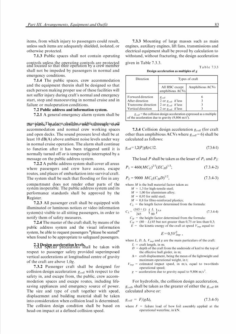
5/12/2018 High Speed Craft Rusa - slidepdf.com
http://slidepdf.com/reader/full/high-speed-craft-rusa 84/167
items, from which injury to passengers could result,unless such items are adequately shielded, isolated, orotherwise protected.
7.1.3 Public spaces shall not contain operating
controls unless the operating controls are protectedand located so that their operation by a crew membershall not be impeded by passengers in normal andemergency conditions.
7.1.4 The public spaces, crew accommodationand the equipment therein shall be designed so thateach person making proper use of these facilities willnot suffer injury during craft's normal and emergencystart, stop and manoeuvring in normal cruise and infailure or maloperation conditions.
7.2 Public address and information system.
7.2.1 A general emergency alarm system shall be
provided. The alarm shall be audible throughout allthe public spaces, corridors and stairways, crewaccommodation and normal crew working spacesand open decks. The sound pressure level shall be atleast 10 dB(A) above ambient noise levels under wayin normal cruise operation. The alarm shall continueto function after it has been triggered until it isnormally turned off or is temporarily interrupted by amessage on the public address system.
7.2.2 A public address system shall cover all areaswhere passengers and crew have access, escaperoutes, and places of embarkation into survival craft.The system shall be such that flooding or fire in any
compartment does not render other parts of thesystem inoperable. The public address system and itsperformance standards shall be approved by theRegister.
7.2.3 All passenger craft shall be equipped withilluminated or luminous notices or video informationsystem(s) visible to all sitting passengers, in order tonotify them of safety measures.
7.2.4 The master of the craft shall, by means of thepublic address system and the visual informationsystem, be able to request passengers "please be seated"when found to be appropriate to safeguard passengers.
7.3 Design acceleration levels.7.3.1 Special precautions shall be taken with
respect to passenger safety provided superimposedvertical accelerations at longitudinal centre of gravityof the craft are above 1,0 g.
7.3.2 Passenger craft shall be designed forcollision design acceleration gcoll with respect to thesafety in, and escape from, the public, crew accom-modation spaces and escape routes, including life-saving appliances and emergency source of power.The size and type of craft together with speed,displacement and building material shall be takeninto consideration when collision load is determined.The collision design condition shall be based onhead-on impact at a defined collision speed.
7.3.3 Mounting of large masses such as mainengines, auxiliary engines, lift fans, transmissions andelectrical equipment shall be proved by calculation towithstand, without fracturing, the design acceleration
given in Table 7.3.3.
7.3.4 Collision design acceleration gcoll (for craftother than amphibious ACVs where gcoll =6) shall becalculated as follows:
gcoll =1,2(P/gD)412. (7.3.4-1)
The load P shall be taken as the lesser of P1 and P2:
P1 = 460(MC L)2/3(EC H )1/3; (7.3.4-2)
P2 = 9000 MC L(C H D)1/2, (7.3.4-3)
where M is the hull material factor taken as:M = 1,3 for high-tensile steel;M = 1,00 for aluminium alloy;M = 0,95 for mild steel;M = 0,8 for fibre-reinforced plastics;
C L = the length factor determined from the formula:
C L=(165+L)
245{ L
80}0,4 (7.3.4-4)
C H = the height factor determined from the formula:C H = (80 ± L)/45 but not greater than 0,75 or less than 0,3;E = the kinetic energy of the craft at speed V imp equal to:
E=0,5V 2imp ,
where L, D, D, V imp and g are the main particulars of the craft:
L = craft length, in m;D = depth of the craft from the underside of keel to the top of
the effective hull girder, in m;D= craft displacement, being the mean of the lightweight and
maximum operational weight, in t;V imp = estimated impact speed, in m/s, equal to two-thirds
operational speed; g = acceleration due to gravity equal to 9,806 m/s 2.
For hydrofoils, the collision design acceleration, gcoll , shall be taken as the greater of either the gcoll ascalculated above or:
gcoll = F/( gD), (7.3.4-5)
where F = failure load of bow foil assembly applied at theoperational waterline, in kN.
Part III. Arrangements, Equipment and Outfit 83
Direction Types of craft
All HSC exceptamphibious ACVs
Amphibious ACVs
Forward directionAfter directionTransverse directionVertical direction
gcoll
2 or gcoll if less
2 or gcoll if less
2 or gcoll if less
6333
gcoll = the collision design acceleration expressed as a multipleof the acceleration due to gravity (9,806 m/s2).
T a b l e 7.3.3Design acceleration as multiples of g
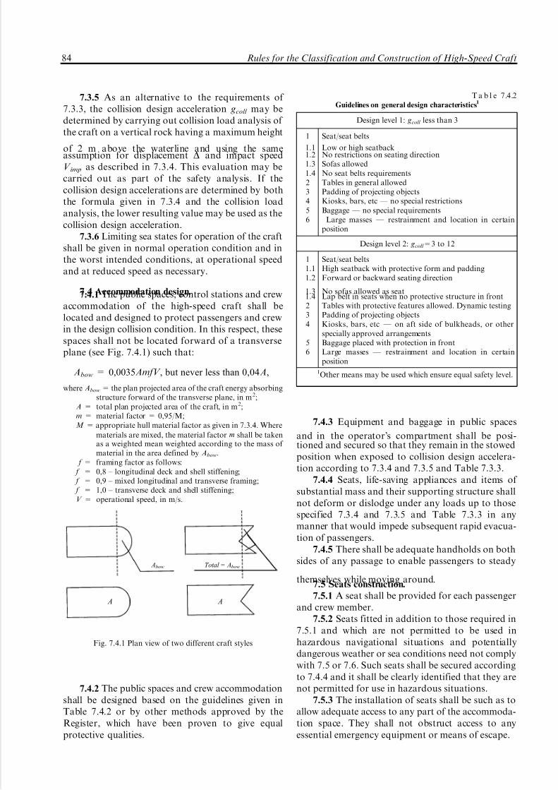
5/12/2018 High Speed Craft Rusa - slidepdf.com
http://slidepdf.com/reader/full/high-speed-craft-rusa 85/167
7.3.5 As an alternative to the requirements of 7.3.3, the collision design acceleration gcoll may bedetermined by carrying out collision load analysis of the craft on a vertical rock having a maximum height
of 2 m above the waterline and using the sameassumption for displacement D and impact speedV imp as described in 7.3.4. This evaluation may becarried out as part of the safety analysis. If thecollision design accelerations are determined by boththe formula given in 7.3.4 and the collision loadanalysis, the lower resulting value may be used as thecollision design acceleration.
7.3.6 Limiting sea states for operation of the craftshall be given in normal operation condition and inthe worst intended conditions, at operational speedand at reduced speed as necessary.
7.4 Accommodation design.7.4.1 The public spaces, control stations and crewaccommodation of the high-speed craft shall belocated and designed to protect passengers and crewin the design collision condition. In this respect, thesespaces shall not be located forward of a transverseplane (see Fig. 7.4.1) such that:
Abow = 0,0035AmfV , but never less than 0,04A,
where Abow = the plan projected area of the craft energy absorbingstructure forward of the transverse plane, in m2;
A = total plan projected area of the craft, in m2;m = material factor = 0,95/M;M = appropriate hull material factor as given in 7.3.4. Where
materials are mixed, the material factor m shall be takenas a weighted mean weighted according to the mass of material in the area defined by Abow.
f = framing factor as follows: f = 0,8 ± longitudinal deck and shell stiffening; f = 0,9 ± mixed longitudinal and transverse framing; f = 1,0 ± transverse deck and shell stiffening;V = operational speed, in m/s.
7.4.2 The public spaces and crew accommodationshall be designed based on the guidelines given inTable 7.4.2 or by other methods approved by theRegister, which have been proven to give equalprotective qualities.
7.4.3 Equipment and baggage in public spaces
and in the operator's compartment shall be posi-tioned and secured so that they remain in the stowedposition when exposed to collision design accelera-tion according to 7.3.4 and 7.3.5 and Table 7.3.3.
7.4.4 Seats, life-saving appliances and items of substantial mass and their supporting structure shallnot deform or dislodge under any loads up to thosespecified 7.3.4 and 7.3.5 and Table 7.3.3 in anymanner that would impede subsequent rapid evacua-tion of passengers.
7.4.5 There shall be adequate handholds on bothsides of any passage to enable passengers to steady
themselves while moving around.7.5 Seats construction.
7.5.1 A seat shall be provided for each passengerand crew member.
7.5.2 Seats fitted in addition to those required in7.5.1 and which are not permitted to be used inhazardous navigational situations and potentiallydangerous weather or sea conditions need not complywith 7.5 or 7.6. Such seats shall be secured accordingto 7.4.4 and it shall be clearly identified that they arenot permitted for use in hazardous situations.
7.5.3 The installation of seats shall be such as toallow adequate access to any part of the accommoda-tion space. They shall not obstruct access to anyessential emergency equipment or means of escape.
Abow Total = Abow
A A
Fig. 7.4.1 Plan view of two different craft styles
Design level 1: gcoll less than 3
1
1.11.21.31.423456
Seat/seat belts
Low or high seatbackNo restrictions on seating directionSofas allowedNo seat belts requirementsTables in general allowedPadding of projecting objectsKiosks, bars, etc _ no special restrictionsBaggage _ no special requirements
Large masses _ restrainment and location in certainposition
Design level 2: gcoll =3 to 12
11.11.2
1.31.4234
56
Seat/seat beltsHigh seatback with protective form and paddingForward or backward seating direction
No sofas allowed as seatLap belt in seats when no protective structure in frontTables with protective features allowed. Dynamic testingPadding of projecting objectsKiosks, bars, etc _ on aft side of bulkheads, or otherspecially approved arrangementsBaggage placed with protection in frontLarge masses _ restrainment and location in certainposition
1Other means may be used which ensure equal safety level.
T a b l e 7.4.2Guidelines on general design characteristics1
84 Rules for the Classification and Construction of High-Speed Craft

5/12/2018 High Speed Craft Rusa - slidepdf.com
http://slidepdf.com/reader/full/high-speed-craft-rusa 86/167
7.5.4 Seats and their attachments, and thestructure in proximity of the seats, shall have a form,design and construction such as to minimize thepossibility of injury and to avoid trapping of
passengers after the assumed damage in the collisiondesign conditions according to 7.4.1. Dangerousprojections and hard edges shall be eliminated orpadded.
7.5.5 Seats and adjacent parts such as tables shallbe designed for the collision design acceleration asspecified in 7.3.4.
7.5.6 All seats, their supports and their deckattachments shall have good energy-absorbing char-acteristics and shall meet the requirements of Appendix to this Part.
7.6 Safety belts.
7.6.1 One-hand-release belts of three-point typeor belts with shaller harness shall be provided for allseats from which the craft may be operated for allcraft with collision design acceleration gcoll exceeding3 g ( see 7.3.4).
7.6.2 Safety belts shall be provided for passengerseats and, if necessary, for crew members seats toensure safety as specified in Appendix to this Part.
7.7 Exits and means of escape.
7.7.1 Easy, safe and quick access from theoperating compartment to passenger accommodationspaces shall be provided. In order to ensureimmediate assistance of the crew in an emergency
situation, the crew accommodation spaces, includingcabins, shall be located with due regard to easy, safeand quick access to public spaces.
7.7.2 The craft design shall be such that alloccupants may safely evacuate the craft into survivalcraft under all emergency conditions, by day and bynight. The positions of all exits, which may be used inan emergency, and of all life-saving appliances, thepracticability of the evacuation procedure, and theevacuation time to evacuate all passengers and crewshall be demonstrated.
7.7.3 Public spaces, means of escape, exits,
lifejackets stowage places, survival craft stowageplaces, and the embarkation stations shall be clearlyand permanently marked and illuminated as requiredin Part XI "Electrical Equipment".
7.7.4 Each enclosed public space and similarpermanently enclosed space allocated to passengersor crew shall be provided with at least two exits aswidely separated as practical. All exits shall clearlyindicate the directions to the evacuation station andsafe areas. On category A craft and cargo craft, atleast one exit shall give access to the evacuationstation serving the persons in the enclosed spaceconsidered, and all other exits shall give access to aposition on the open deck from which access to anevacuation station is provided. On category B craft,
exits shall provide access to the alternative safe arearequired by 2.5.4, Part VI "Fire Protection"; externalroutes may be accepted providing that the require-ment of 7.7.3 and 7.7.11 are complied with.
7.7.5 Subdivision of public spaces to providerefuge in case of fire may be required in compliancewith the requirements 2.3.1 and 2.5.4, Part VI "FireProtection".
7.7.6 Exit doors shall be capable of being readilyoperated from inside and outside the craft in daylightand in darkness. The means of operation shall beobvious, rapid and of adequate strength. Doors alongescape flow shall, wherever appropriate, open in thedirection of escape flow from the space served.
7.7.7 The closing, latching and locking arrange-ments for exits shall be such that it is readily apparent
to the appropriate crew member when the doors areclosed and in a safe operational condition, either indirect view or by an indicator. The design of externaldoors shall be such as to minimize the possibility of
jamming by ice or debris.7.7.8 The craft shall have a sufficient number of
exits, which are suitable to facilitate the quick, andunimpeded escape of persons wearing approvedlifejackets in emergency conditions, such as collisiondamage or fire.
7.7.9 Sufficient space for a crew member shall beprovided adjacent to exits for ensuring the rapidevacuation of passengers.
7.7.10 All exits, together with their means of opening, shall be adequately marked for the guidanceof passengers. Adequate marking shall also beprovided for the guidance of rescue personnel outsidethe craft.
7.7.11 Footholds, ladders, etc., provided to giveaccess from the inside to exits shall be of rigidconstruction and permanently fixed in position.Permanent handholds shall be provided whenevernecessary to assist persons using exits, and shall besuitable for conditions when the craft has developedany possible angles of list and trim.
7.7.12 At least two unobstructed evacuationpaths shall be available for the use of each person.Evacuation paths shall be disposed such thatadequate evacuation facilities will be available inthe event of any likely damage or emergencyconditions. Evacuation paths shall have adequatelighting supplied from the main and emergencysources of power.
7.7.13 The width of corridors, doorways andstairways which form part of the evacuation pathsshall be not less than 900 mm for passenger craft and700 mm for cargo craft. This width may be reducedto 600 mm for corridors, doorways and stairwaysserving spaces where persons are not normallyemployed. There shall be no protrusions in evacua-
Part III. Arrangements, Equipment and Outfit 85

5/12/2018 High Speed Craft Rusa - slidepdf.com
http://slidepdf.com/reader/full/high-speed-craft-rusa 87/167
tion paths, which could cause injury, ensnare cloth-ing, damage lifejackets or restrict evacuation of disabled persons.
7.7.14 Adequate notices shall be provided to
direct passengers to exits.7.7.15 Provision shall be made on board for
embarkation stations to be properly equipped forevacuation of passengers into life-saving appliances.Such provision shall include handholds, anti-skidtreatment of the embarkation deck, and adequatespace, which is clear of cleats, bollards and similarfittings.
7.7.16 Main propulsion machinery spaces and ro-ro spaces shall be provided with two means of escapeleading to a position outside the spaces from which asafe route to the evacuation stations is available. One
means of escape from the main propulsion machineryspaces shall avoid direct access to any ro-ro space.Main propulsion machinery spaces having a length of less than 5 m and not being routinely entered orcontinuously manned, may be provided with a singlemeans of escape.
7.8 Baggage rooms, stores and cargo compart-
ments.
7.8.1 Provision shall be made to prevent shiftingof baggage, stores and cargo compartment contents,having due regard to occupied compartments andacceleration likely to arise. If safeguarding bypositioning is not practicable, adequate means of
restraint for baggage, stores and cargo shall beprovided. Shelves and overhead shelves for storageof carry-on baggage in public spaces shall beprovided with adequate means to prevent luggagefrom falling out in any conditions that may occur.
7.8.2 Controls, electrical equipment, high-tempera-ture parts, pipelines or other items, the damage orfailure of which could affect the safe operation of thecraft or which may require access by crew membersduring a voyage, shall not be located in baggage, storeand cargo compartments unless such items areadequately protected so that they cannot be damaged
or operated inadvertently by loading, by unloading orby movement of the contents of the compartment.
7.8.3 Loading limits, if necessary, shall bedurably marked in those compartments.
7.8.4 Having regard to the purpose of the craft,the closures of the exterior openings of the baggageand cargo compartment as well as special categoryspaces shall be appropriately weathertight.
8 GUARD RAILS, BULWARKS
8.1 Guard rails or bulwarks shall be fitted on allexposed parts of decks to which crew or passengers
have access. Alternative arrangements such as safetyharnesses and jack-stays may be accepted if theyprovide an equivalent level of safety. The height of the bulwarks or guard rails shall be at least 1 m from
the deck. Where this height would interfere with thenormal operation of the craft, a lesser height may beapproved on agreement with the Register.
8.2 The opening below the lowest course of theguard rails shall not exceed 230 mm. The othercourses shall be not more than 380 mm apart. In caseof craft with rounded gunwales the guard railsupports shall be placed on the flat of the deck.
8.3 Satisfactory means (in the form of guard rails,life lines, gangways or underdeck passages, etc.) shallbe provided for the protection of the crew in gettingto and from their quarters, the machinery space and
all other parts used in the necessary work of the craft.8.4 Deck cargo carried on any craft shall be sostowed that any opening which is in way of the cargoand which gives access to any space used in the workof the craft can be properly closed and securedagainst the admission of water. Effective protectionfor the crew in the form of guard rails or life linesshall be provided above the deck cargo if there is noconvenient passage on or below the deck of the craft.
9 EMERGENCY OUTFIT
9.1 The provision of emergency outfit shall begoverned by a structural type of HSC and conditionsof its operation and is subject to special considerationby the Register in each case. In all cases, emergencyoutfit shall include a lightened soft collision mat andwooden bars.
9.2 Emergency outfit shall be stored at least intwo emergency stations, one of which shall be in themachinery space. Emergency stations may be specialplaces, boxes or places allocated on deck or in spaces.In the emergency station of the machinery space the
outfit necessary for carrying out the emergencyoperations inside the space shall be stored; the restof emergency outfit shall be stored in the emergencystations located above the bulkhead decks. On shipsof less than 45 m in length it is allowed to locate theemergency station below the bulkhead deck oncondition that free access to the station is provided.On ships 31 m in length and below it is allowed tostore emergency outfit only in one emergency station.
9.3 A free passage shall be provided in front of the emergency station; the width of the passage shallbe selected depending on the overall dimensions of the outfit stored in the station but not less than 0,8 m.On ships 31 m in length and less, the width of thepassage may be reduced to 0,6 m.
86 Rules for the Classification and Construction of High-Speed Craft

5/12/2018 High Speed Craft Rusa - slidepdf.com
http://slidepdf.com/reader/full/high-speed-craft-rusa 88/167
Passages to emergency stations shall be straightand short as far as practicable.
9.4 Items of emergency outfit (other thancollision mats) or cases for their storage shall be
painted blue either entirely or in stripes. Cases foremergency equipment shall have a distinct inscription
showing the name of the material, weight andwarranted storage period.
9.5 Emergency stations shall be provided withdistinct inscriptions "Emergency station". In addi-
tion, notices showing location of the emergencystation shall be posted in passages and on decks.
A P P E N D I X
CRITERIA FOR TESTING AND EVALUATION OF REVENUE AND CREW SEATS
1. PURPOSE AND SCOPE
1.1 This Appendix shall provide requirements for
revenue and crew seats, seat anchorage and seataccessories and their installation to minimize occu-pant injury and/or obstacles for evacuation of peopleif the craft suffers a collision.
2. STATIC SEAT TESTS
2.1 The requirements of this Section are applic-able to all crew and revenue seats.
2.2 All seats to which this Section applies, alongwith their supports and deck attachments, shall bedesigned to withstand at least the following staticforces applied in the direction of the craft:
.1 forward direction Ð a force of 2,25 kN;
.2 after direction Ð a force of 1,5 kN;
.3 transverse direction Ð a force of 1,5 kN;
.4 vertically downward Ð a force of 2,25 kN;
.5 vertically upward Ð a force of 1,5 kN.A seat shall comprise a frame, bottom and back.
Forces applied in the fore or aft direction of the seatshall be applied horizontally to the seat back 350 mmabove the seat bottom. Forces applied in thetransverse seat direction shall be applied horizontally
to the seat bottom. Vertical upward forces shall beevenly distributed to the corners of the seat bottomframe. Vertical downward forces shall be uniformlydistributed over the seat bottom. If a seating unitconsists of more than one seating position, theseforces shall be applied at each seating positionconcurrently during the tests.
2.3 When the forces are applied to a seat,consideration shall be given to the direction in whichthe seat shall face in each craft. For example, if theseat faces sideways, the transverse craft force isapplied fore and aft to the seat and the forward craft
force is applied transversely to the seat.2.4 Each seating unit to be tested shall beattached to the support structure similar to the
manner in which it will be attached to the deckstructure in the craft. Although a rigid supportstructure can be used for these tests, a supportstructure, having the same strength and stiffness as
the support structure in the craft, is preferred.2.5 The forces described in 2.2.1 to 2.2.3 shall be
applied to a seat through a cylindrical surface havinga radius of 80 mm and a width at least equal to thewidth of the seat. The surface shall be equipped withat least one force transducer able to measure theforces applied.
2.6 The seat shall be considered acceptable if:.1 under the influence of the forces referred to in
2.2.1 to 2.2.3, the permanent displacement measuredat the point of application of the force is not morethan 400 mm;
.2 no part of the seat, the seat mountings or theaccessories become completely detached during thetests;
.3 the seat remains firmly held, even if one ormore of the anchorages is partly detached;
.4 all of the locking systems remain locked duringthe entire test but the adjustment and locking systemsneed not be operational after the tests; and
.5 rigid parts of the seat with which the occupantmay come into contact shall present a curved surfacewith a radius of at least 5 mm.
2.7 The requirements of Section 3 may be used inlieu of the requirements of this section provided that
the accelerations used for the tests are at least 3 g.
3. DYNAMIC SEAT TESTS
3.1 The requirements of this Section are applic-able in addition to those in 2.1 for crew and revenueseats in craft having a design collision load of 3 g orgreater.
3.2 All seats for which this Section applies, theseat supporting structure, the attachment to the deck
structure, the lap belt, if installed, and shallerharness, if installed, shall be designed to withstandthe maximum acceleration force that can be imposed
Part III. Arrangements, Equipment and Outfit 87

5/12/2018 High Speed Craft Rusa - slidepdf.com
http://slidepdf.com/reader/full/high-speed-craft-rusa 89/167
upon them during a design collision. Considerationshall be given to the orientation of the seat relative tothe acceleration force (i. e. whether the seat isforward-, aft-, or side-facing).
3.3 The acceleration pulse to which the seat issubjected shall be representative of the collision time-history of the craft. If the collision time-history is notknown, or cannot be simulated, the acceleration time-history envelope shown in the figure can be used.
3.4 In the test frame, each seat unit and itsaccessories (e. g., lap belts and shaller harnesses) shallbe attached to the support structure similar to themanner in which it will be attached in the craft. Thesupport structure can be a rigid surface; however, asupport structure having the same strength andstiffness as the support structure in the craft ispreferred. Other seats and/or tables with which theoccupant may come in contact during a collision shallbe included in the test frame in orientation and with amethod of attachment typical of that in the craft.
3.5 During the dynamic seat test, a fiftieth
percentile anthropomorphic test dummy, suitablefor the test being conducted, shall be placed in theseat in an upright seating position. If a typical seatingunit is composed of more than one occupant seat, atest dummy shall be placed in each occupant seat inthe unit. The dummy, or dummies, shall be secured inthe seat unit in accordance with procedures recog-nized by the Register and be secured using only thelap belt and shaller harness if they are installed. Thetray tables and other such devices shall be placed inthe position that would cause the greatest potentialfor an occupant to become injured.
3.6 The test dummy shall be instrumented andcalibrated in accordance with the requirements of arecognized national standard, so as to permit, as aminimum, calculation of the head injury criterion,
calculation of the thoracic trauma index, measure-ment of force in the femur, and measurement, if possible, of extension and flexion of the neck.
3.7 If more than one dummy is used in the tests,the dummy located in the seat having the highestpotential for an occupant to be injured shall be theone instrumented. The other dummy or dummiesneed not be instrumented.
3.8 The tests shall be conducted and theinstrumentation shall be sampled at a rate sufficientto reliably show response of the dummy in accor-dance with the requirements of standard ISO 6487.
3.9 The seat unit tested in accordance with therequirements of this Section shall be consideredacceptable if:
.1 the seat unit and tables installed in the seat unitdo not become dislodged from the supporting deckstructure and do not deform in a manner that wouldcause the occupant to become trapped or injured;
.2 the lap belt, if installed, remains attached andon the test dummy's pelvis during the impact. Theshaller harness, if installed, remains attached and inthe immediate vicinity of the test dummy's shallerduring the impact. After the impact, the releasemechanisms of any installed lap belt and shaller
harness shall be operative;.3 the following acceptability criteria are met:.3.1 the head injury criterion (HIC), calculated in
accordance with the formula, does not exceed 500:
HIC=(t27t1)[ 1t27t1
$t2
t1
a(t)dt]2,5
,
where t1 and t2 are the beginning and ending time (in seconds) of the interval in which the HIC is a maximum. The term a
(t) is the resultant measured acceleration in the head of the dummy, in g;
.3.2 the thoracic trauma index (TTI), calculatedin accordance with the formula, does not exceed 30 g
except for periods totalling less than 3 ms:
TTI= gr7 gls
2or acceleration at the center of gravity
where gr is the acceleration, in g, of either upper or lower rib; gls is the acceleration, in g, of lower spine;
3.3 the force in the femur does not exceed 10 kNexcept that it cannot exceed 8 kN for periods totallingmore than 20 ms;
.4 loads on the upper torso harness straps do notexceed 7,8 kN or a total of 8,9 kN if dual strap areused.
g/g coll
1,0
0,7
10 20 70 80 90 150 Time (ms)
Fig. 3.3 Acceleration time-history envelope
88 Rules for the Classification and Construction of High-Speed Craft

5/12/2018 High Speed Craft Rusa - slidepdf.com
http://slidepdf.com/reader/full/high-speed-craft-rusa 90/167
1 SCOPE OF APPLICATION
1.1 This Part applies to the enclosed (decked)type craft.
1.2 The requirements of this Part do not apply tothe light-craft loading condition.
2 DEFINITIONS AND EXPLANATIONS
2.1 Definitions and explanations relating togeneral terminology are given in "General" of the
present Rules and in Part IV "Stability" of the Rulesfor the Classification and Construction of Sea-GoingShips.
2.2 For the purpose of this Part, the followingadditional definitions are given.
A i r - c u s h i o n s k i r t is a downwardly ex-tending, flexible structure used to contain or dividean air cushion.
M u l t i h u l l c r a f t is a craft which, in anynormally achievable operating trim or heel angle, hasa rigid hull structure which penetrates the surface of the sea over more than one discrete area.
M o n o h u l l c r a f t means any craft, which is
not a multihull craft.F u l l y s u b m e r g e d f o i l is a foil having no
lift components piercing the surface of the water inthe foil-borne mode.
D o w n f l o o d i n g p o i n t means any opening,irrespective of size, that would permit passage of water through a water/weathertight structure (e.g.opening windows), but excludes any opening keptclosed in compliance with the requirements of Chapter 6, Part III "Arrangements, Equipment andOutfit" at all times other than when required foraccess or for operation of portable submersible bilge
pumps in an emergency (e.g. non-opening windowsof similar strength and weathertight integrity to thestructure in which they are installed).
H u l l s l o p e a n g l e is an angle lying in thevertical plane perpendicular to the craft side or bowor stern and measured along the shortest arc betweenthe base line and the lowest knuckle of the craft sideor bow or stern (Fig. 2.2).
3 GENERAL TECHNICAL REQUIREMENTS
3.1 All crafts shall be provided with stabilitycharacteristics and stabilization systems adequate forsafety:
when the craft is operated in the displacement,operational (non-displacement) modes and duringthe transitional mode;
in transfer of the craft from any mode to thedisplacement mode in case of any system malfunction.3.1.1 Stability may be verified by calculation
and/or experimental methods.Other means of demonstrating compliance with
the requirements of this Part may be accepted,provided that the method chosen can be shown toprovide an equivalent level of safety. Such methodsmay include:
mathematical simulation of dynamic behaviour;scale model testing;full-scale trials.The adequacy of mathematical simulations shall
be demonstrated by correlation with full-scale ormodel tests for the appropriate type of craft. It maybe appropriate to use mathematical simulations tohelp to identify the more critical scenarios forsubsequent physical testing.
Model or full-scale trials and/or calculations (asappropriate) shall also include consideration of thefollowing known stability hazards to which high-speed craft are known to be liable, according to crafttype:
.1 directional instability, which is often coupledto roll and pitch instabilities;
.2 broaching and bow diving in following seas atspeeds near to wave speed, applicable to most types;
.3 bow diving of planing monohulls and cata-marans due to dynamic loss of longitudinal stabilityin relatively calm seas;
.4 reduction in transverse stability with increasingspeed of monohulls;
.5 porpoising of planing monohulls, beingcoupled pitch and heave oscillations, which canbecome violent;
.6 chine tripping, being a phenomenon of planingmonohulls occurring when the immersion of a chinegenerates a strong capsizing moment;
.7 plough of air-cushion vehicles, either long-itudinal or transverse, as a result of bow or side skirt
PART IV. STABILITY
Part IV. Stability 89
a
Fig. 2.2

5/12/2018 High Speed Craft Rusa - slidepdf.com
http://slidepdf.com/reader/full/high-speed-craft-rusa 91/167
tuck-under or sudden collapse of skirt geometry,which, in extreme cases, can result in capsize;
.8 pitch instability of SWATH (small waterplanearea twin hull) craft due to the hydrodynamic
moment developed as a result of the water flow overthe submerged lower hulls;
.9 reduction in effective metacentric height (rollstiffness) of surface effect ship (SES) in high speedturns compared to that of straight course, which canresult in sudden increase in heel angle and/or coupledroll and pitch oscillations; and
.10 resonant rolling of SES in beam seas, which,in extreme cases, can result in capsize.
Verification procedures and calculation pro-grammes shall be approved by the Register.
3.1.2 Stability characteristics of the designed
HSC in the displacement mode may be determinedusing calculation methods; in the operational andtransitional modes, by calculations or experimentallyby testing a model of the designed craft or on thebasis of the results of full-scale trials of the craftprototype.
For craft having a distinguishing mark AUTstab inthe class notation, data proving sufficient stability of the craft in case of possible failures in the stabilizationcontrols and their drives shall be presented.
3.1.3 Stability characteristics of the craft shall befinally corrected in the displacement mode inaccordance with the inclining test results (4.1), in
the operational and transitional modes according tothe experimental data.
An ability of the craft to keep the operational andtransitional modes under the worst intended condi-tions shall be proved experimentally during deliveryseaworthiness trials of the craft.
Suitable calculations shall be carried out and/ortests conducted to demonstrate that, when operatingwithin approved operational limitations, the craftwill, after a disturbance causing roll, pitch, heave orheel due to turning or any combination thereof,return to the original attitude.
Where calculations are employed, it shall first beshown that they correctly represent dynamic beha-viour within the operational limitations of the craft.
3.2 HSC stability shall be verified for the loadingconditions referred to in 13.1.1, 13.1.2, 13.2.1 of thepresent Rules.
3.3 If in the process of normal service of a craftthe worse loading variants with regard to stability areintended in comparison with those mentioned in 3.2,the stability for those loading variants shall beverified also.
3.4 The requirements of 1.4.1, 1.4.2.1 to 1.4.2.3,1.4.2.5 to 1.4.7, 1.4.9 and 1.4.10, Part IV "Stability"of the Rules for the Classification and Constructionof Sea-Going Ships apply to HSC in the displacement
mode. Calculations of HSC stability levers shall becarried out with respect to accompanying trim.
3.5 Unless provided otherwise, the requirementof 12.2 shall be met in the transitional mode under
conditions referred to in 3.2; the maximum angles of heel shall not exceed 158.
3.6 On completion of loading of the craft andprior to its departure on a voyage, the master shalldetermine the trim and stability of the craft and alsoto ascertain and record in the ship's log that the craftis in compliance with stability criteria of the relevantrequirements. The Register may accept the use of anelectronic loading and stability computer or equiva-lent means for this purpose.
4 INCLINING AND STABILITY INFORMATION
4.1 Every craft, on completion of build, shall beinclined and the elements of its stability determined.When an accurate inclining is not practical, thelightweight displacement and centre of gravity shallbe determined by a lightweight survey and accuratecalculation.
4.2 Where an accurate inclining experiment isimpractical owing to the height of the centre of gravity (KG) being less than one third of the initialtransverse metacentric height (GMT), the Register
may accept estimation of KG by detailed calculationin place of an inclining test. In such a case, the light-weight check shall be undertaken to confirm thecalculated light-ship characteristics, including thelongitudinal center of gravity of the craft. Thecalculation results may be accepted as true if thedata resulting from the light-weight check differ fromthe measured ones for not more than 2 per cent bythe light-ship displacement and for not more than1 per cent of the ship's length between perpendicularsby the light-ship longitudinal centre of gravity.
4.3 The master shall be supplied by the owner
with reliable information relating to the stability of the craft in accordance with the provisions of thisSection. The Information on Stability shall, beforebeing issued to the master, be submitted to theRegister for approval, together with a copy thereof for their retention.
The Information on Stability of a HSC shallincorporate the information on provision of stabilityof the craft in different modes of operation, as well asall the restrictions specified for the craft, such asdistances allowed to proceed from a place of refugeand navigation seasons, sea state and wave height,angles to safely put the rudder over from one side tothe other, etc. In compiling the Information onStability, one shall be guided by Appendix 1, Part IV
90 Rules for the Classification and Construction of High-Speed Craft

5/12/2018 High Speed Craft Rusa - slidepdf.com
http://slidepdf.com/reader/full/high-speed-craft-rusa 92/167
"Stability" of the Rules for the Classification andConstruction of Sea-Going Ships, having regard tospecific features of HSC and the requirements of thepresent Rules.
4.4 Where any alterations are made to a craft so assignificantly to affect the Information on Stabilitysupplied to the master, amended Information onStability shall be provided. If necessary the craft shallbe re-inclined.
4.5 A report on each inclining or lightweightsurvey (weighting) carried out in accordance with thepresent Rules and of the calculation therefrom of thelightweight condition particulars shall be submittedto the Register for approval, together with a copy fortheir retention. The approved report shall be placedon board the craft by the owner in the custody of the
master and shall incorporate such additions andamendments as the Register may in particular caserequire.
4.6 Following any inclining or lightweight survey,the master shall be supplied with amended Informa-tion on Stability if the Register so requires. TheInformation on Stability shall be submitted to theRegister for approval, together with a copy thereof for their retention, and shall incorporate suchadditions and amendments as the Register may ineach particular case require.
4.7 Information on Stability demonstrating com-pliance with this Part shall be furnished in the form of
a Information on Stability book which shall be kepton board the craft at all times in the custody of themaster. The Information shall include particularsappropriate to the craft and shall reflect the craftloading conditions and mode of operation. Anyenclosed superstructures or deckhouses included inthe cross curves of stability and the critical down-flooding points and angles shall be identified.
At the operating station there shall be plansshowing clearly for each deck and hold the bound-aries of the watertight compartments, the openingstherein with their means of closure and position of
any controls thereof.4.8 Every craft shall have scales of draughts
marked clearly at the bow and stern. In the casewhere the draught marks are not located where theyare easily readable, or operational constraints for aparticular trade make it difficult to read the draughtmarks, then the craft shall be also fitted with areadable draught-indicating system by which the bowand stern draughts can be determined.
For amphibious air-cushion vehicles this may beachieved by the use of draught gauges in conjunctionwith deck datum plates.
4.9 The owner or builder, as appropriate, shallensure that the positions of the draught marks areaccurately determined and that the marks are located
on the hull in a permanent manner. Accuracy of thedraught marks shall be demonstrated to the Registerprior to inclining experiment.
4.10 The requirements of 1.5, Part IV "Stability"
of the Rules for the Classification and Constructionof Sea-Going Ships, apply to HSC.
4.11 Other methods of determining the displace-ment and centre of mass coordinates of the light-weight craft may be used upon agreement with theRegister.
5 DEPARTURES FROM THE RULES
5.1 The requirements of 1.3.4, "General Regula-
tions for the Classification and Other Activity" of theRules for the Classification and Construction of Sea-Going Ships apply to HSC.
5.2 The Register may apply additional require-ments for craft stability in the operational andtransitional modes of HSC fitted with automaticstabilization systems the components of which mayaffect the value of heel.
6 CONDITIONS OF SUFFICIENT STABILITY
6.1 In the worst loading condition in respect of stability out of those referred to in 3.2, stability of thecraft shall meet the following requirements:
.1 a craft without capsizing in the displacementmode and without losing the mode in the operationalmode shall withstand simultaneous action of adynamically applied wind pressure and rolling theparameters of which shall be determined in accor-dance with the requirements given below;
.2 numerical values of parameters of staticstability curve in the displacement mode and thevalue of the corrected initial metacentric height in all
modes shall not be lower than those indicated in thisPart;
.3 icing effect shall be taken into account incompliance with Section 11 of this Part;
.4 stability in service shall comply with therequirements of Section 12 of this Part;
.5 craft stability shall meet the additionalrequirements contained in Section 13 of this Part.
6.2 Where the characteristics of multihull craftare inappropriate for application of the requirementsof Section 13 or the characteristics of monohull craftare inappropriate for application of the requirementsof Sections 8 and 9, the Register may acceptalternative criteria equivalent to those stipulated, asappropriate to the type of the craft and area of
Part IV. Stability 91

5/12/2018 High Speed Craft Rusa - slidepdf.com
http://slidepdf.com/reader/full/high-speed-craft-rusa 93/167
operation. The requirements of Sections 8, 9, 10 and13 may be applied as indicated in Table 6.2.
7 PASSAGE OF CRAFT FROM ONE PORT TO ANOTHER
7.1 The requirements of Part IV "Stability" of theRules for the Classification and Construction of Sea-Going Ships apply to HSC.
8 GENERAL REQUIREMENTS FOR STABILITY
8.1 Weather criterion.
8.1.1 Operation of HSC is restricted by weatherconditions. The conditions are assigned depending on
the intended routes and are specified more exactlybased on the results of trials during deliveryseaworthiness trials of the first and any craft of series as required by the Register.
8.1.2 In the displacement mode stability of HSCother than hydrofoils and multihull craft is consid-ered sufficient as regards weather criterion if the craftcan withstand the combined effects of steady windand rolling with reference to the following:
.1 the craft is subjected to a steady wind pressureacting perpendicular to the craft centreline whichresults in a steady wind heeling lever HL1 (see
Fig. 8.1.2.1);.2 from the resultant angle of heel yh, the craft is
assumed to roll owing to wave action to an amplitudeof rolling yr to windward;
.3 the craft is then subjected to a gust wind pressurewhich results in a gust wind heeling lever HL2;
.4 the areas a and b are compared (shaded areasin Fig. 8.1.2.1). The area b is bounded by the rightinglever curve, a straight line corresponding to lever HL2
and an angle of heel:508 or angle of heel yc which corresponds to the
second intercept between wind heeling lever HL2 andthe righting lever curve; or
angle of heel yd corresponding to the angle of downflooding, whichever is less.
The area a is bounded by the righting lever curve,a straight line HL2 and an angle of heel correspond-ing to amplitude of rolling yr .
Craft stability is considered sufficient as regardsweather criterion if area b is equal to or greater thanarea a;
.5 the permissible angle of heel y0 due to steadywind shall not exceed 168 or the angle equal to 0,8
times the angle of deck edge immersion, whichever isless. In this case, where the angle of heel exceeds 108,efficient non-slip deck surfaces and suitable holdingpoints shall be provided as specified in 4.4.1.1, Part V"Reserve of Buoyancy and Subdivision";
.6 the wind heeling lever HL1, in m, is assumed tobe a constant value at all angles of inclination andshall be calculated as follows:
HL1=PAZ
1000 gD, (8.1.2.6)
where: P =500( V w
26)
2
_ steady wind pressure, in N/m2;
V w = wind speed corresponding to the worst intended condi-tions, in m/s;
Z = windage area lever; it is assumed equal to the verticaldistance from the centre of windage to the centre of thewaterline lateral area or approximately to a point at onehalf of the draught, in m;
A = windage area, in m2;D = displacement of the craft, in t; g =9,81 m/s2.
The heeling lever HL2 is equal to 1,5 HL1.In assessing the roll angle yr account shall be
taken of the roll damping characteristics of individualcraft, which may alternatively be derived from modelor full-scale tests using the procedure for determiningthe angle yr given in 13.3.1.2.1.5.3. Hulls with
GMT Angle of maximum righting lever GZ
4258 >258
43 m
>3 m
Sections 8, 9, 10 and 13
Sections 13
Sections 8, 9, 10
Sections 8, 9 and 13
GMT = initial transverse metacentric height, in m, underthe load corresponding to the design waterline corrected forfree surface effects of liquids.
T a b l e 6.2Application of the requirements for stability of monohull
and multihull craft
lever
b
HL1
HL2
ycyd yh
yr
ya
Fig. 8.1.2.1yh=angle of heel under action of steady wind;
yr =angle of rolling;yd =angle of downflooding;
yc=angle of second intercept between a straight lineHL2 and GZ curve;
HL1=steady wind heeling lever;HL2=gust wind heeling lever
92 Rules for the Classification and Construction of High-Speed Craft

5/12/2018 High Speed Craft Rusa - slidepdf.com
http://slidepdf.com/reader/full/high-speed-craft-rusa 94/167
features, which greatly increase damping, such asimmersed sidehulls, substantial arrays of foils, orflexible skirts, are likely to experience significantlysmaller magnitudes of roll angle. For such craft,
therefore, the roll angle shall be derived from modelor full-scale tests or, in the absence such data, shall betaken as 158.
8.1.3 Amplitudes of rolling are determined in thefollowing manner:
.1 amplitudes of rolling for the displacement andoperational modes shall be calculated using theprocedures agreed with the Register or obtainedfrom the data of experimental studies;
.2 if calculations or the data of experimentalstudies are lacking, the amplitude of rolling isassumed to be equal to yr =158;
.3 in determining the amplitude of rolling bymeans of experiments, it shall be determined as anamplitude of irregular rolling with 2 per cent of exceeding level and craft beam to the waves theintensity of which corresponds to:
in the operational mode _ the worst intendedconditions;
in the displacement mode _ critical designconditions;
.4 the amplitude of rolling of an air-cushionvehicle in the operational mode is assumed equal tothat in the cushion-borne mode; for all types of HSCin the displacement mode it shall be determined for
the craft without motion.8.1.4 The assumed design moment of losing the
operational mode M 'c shall be determined by amethod approved by the Register. The recommendedprocedure for determination of M 'c is given inAppendix 1 to this Part.
9 STATIC STABILITY CURVE
9.1 The area under the righting lever curve (GZ
curve) shall not be less than 0,07 m´rad up to y=158
when the maximum righting lever (GZ ) occurs aty=158 and 0,055 m´rad up to y=308 when themaximum righting lever (GZ ) occurs at y=308 orover. Where the maximum righting lever occurs atangles of heel between y=158 and y=308, thecorresponding area under the righting momentscurve shall be not less than:
A=0,055+0,001 (3087ymax), m´rad, (9.1)
where ymax=the angle of heel, in deg., at which the righting leverreaches its maximum.
9.1.1 The area under the righting lever curvebetween y=308 and y=408 or between y=308 andthe angle of flooding y f , if this angle is less than 408,shall not be less than 0,03 m´rad.
9.1.2 The righting lever GZ shall be at least 0,20m at an angle of heel equal to or greater than 308.
9.1.3 The maximum righting lever shall occur atan angle of heel not less than 158.
9.2 Characteristics of static stability curves of air-cushion vehicles in the cushion-borne mode shall bedetermined according to the methods approved bythe Register.
10 METACENTRIC HEIGHT
10.1 The corrected initial metacentric heightunder all loading conditions and in all modes shallbe not less than 0,15 m.
11 ALLOWANCE FOR ICING
11.1 The possibility of HSC operation underconditions of likely icing and design rate of icing aresubject to special consideration by the Register ineach particular case.
The recommended method of taking allowancefor icing is given in Appendix 2.
12 STABILITY IN SERVICE
12.1 The stability of the craft in the displacementmode shall be such that, when in still waterconditions, the inclination of the craft from thehorizontal in any direction would not exceed 108under all permitted cases of loading and uncontrolledpassenger movements as may occur.
Hydrofoil craft fitted with surface-piercing and/or fully submerged foils shall have sufficient stabilityunder all permitted cases of loading to comply with
the relevant provisions of 13.3 and maintain a heelangle of less than 108 when subjected to the greater of the heeling moments referred to in 13.3.1.2.
12.2 Under weather conditions up to the worstintended conditions, the time to pass from thedisplacement mode to the operational mode and viceversa shall not exceed 2 min unless it is proved to theRegister that no substantial reduction of stabilityoccurs during this transition.
12.3 It shall be proved by calculations or by teststhat in the operational and transitional modes withinthe approved operational limitations, the craft will,after a disturbance causing heel, pitch, heave, roll orany combination thereof, return to the originalattitude without occurrence of natural oscillations.
Part IV. Stability 93

5/12/2018 High Speed Craft Rusa - slidepdf.com
http://slidepdf.com/reader/full/high-speed-craft-rusa 95/167
12.4 It shall be proved that no forces will arise inthe operational mode on surface-piercing structuresor appendages subsequent to collision with floatingor submerged objects which might result in danger-
ous heel, trim or loss of stability.12.5 It shall be proved that in case of any fault of
the craft that can adversely affect stability in thetransitional and operational modes provision is madefor the safe transition of the craft into the displace-ment mode.
12.6 An inward angle of heel due to turning shallbe provided in still water in the operational mode.Otherwise, it shall be proved to the Register thatturning of the craft at the speeds and angles of putting-over of the steering controls where theinward angle of heel is not provided will be safe. In
all cases, the heel due to turning shall not exceed 8 8.12.7 Stability of the craft in the following sea inthe operational mode shall be proved by testing afull-scale craft. In the following and quartering seasunder the worst permissible conditions and the worstloading condition as regards stability as well as incase of turning under such conditions from thefollowing sea to the head sea, the maximum angle of heel shall not exceed the angle of flooding or 0,6 of the angle corresponding to the lever HL2 accordingto 8.1.2 or 128, whichever is the less.
For the verification of characteristics of stabilityunder the worst permissible conditions model tests
shall be used. The method of model tests shall beapproved by the Register.
12.8 The verification methods under 12.1 to 12.7and the restrictions set up shall be agreed with theRegister.
13 ADDITIONAL REQUIREMENTS FOR STABILITY
13.1 Requirements for passenger craft.
13.1.1 Stability of HSC shall be verified for the
following loading conditions:the craft with full muster of passengers and
cargo, and with full stores;the craft with full muster of passengers and cargo
and 10 per cent of stores;the craft without passengers and cargo, and with
10 per cent of stores.The distribution of passengers, their mass and the
position of their centre of gravity shall be assumed incompliance with the guidelines given below:
.1 the distribution of passengers is 4 persons persquare metre;
.2 each passenger has a mass of 75 kg;
.3 vertical centre of gravity of seated passengers is0,3 m above the seat;
.4 vertical centre of gravity of standing passen-gers is 1,0 m above the deck;
.5 passengers and luggage are considered to be inthe space normally at their disposal;
.6 passengers shall be distributed on availabledeck areas towards one side of the craft on the deckswhere assembly stations are located and in such away that they produce the most adverse heelingmoment;
.7 passengers assumed to be occupying seats shallbe taken as having a vertical centre of gravitycorresponding to being seated, with all othersstanding;
.8 on the decks where assembly stations arelocated, the number of passengers on each deck shallbe that which generates the maximum heeling
moment. Any remaining passengers shall be assumedto occupy decks adjacent to those on which theassembly stations are located, and positioned suchthat the combination of number on each deck and thetotal heeling moment generate the maximum staticheel angle;
.9 passengers shall not be assumed to gain accessto the weather deck nor be assumed to crowdabnormally towards either end of the craft unlessthis is a necessary part of the planned evacuationprocedure;
.10 where there are seats in areas occupied bypassengers, one passenger per seat shall be assumed,
passengers being assigned to the remaining free areasof the deck (including stairways, if appropriate) at therate of four per square metre.
13.1.2 Stability of passenger HSC in all modesshall be additionally verified in still water for theloading condition with full muster of passengers andcargo, and with 10 per cent of stores but with 50 percent of passengers seated on one side from the centre-line of the craft. The other 50 per cent of passengersare accommodated in fore-and-aft passages betweenthe seats according to 3.1.6 to 3.1.8, Part IV"Stability" of the Rules for the Classification and
Construction of Sea-Going Ships.13.1.3 The experimental checking of the lateral
stability of a full-scale HSC shall be made in thefollowing manner:
a force equal to at least twice the double heelingmoment is applied to the craft by moving solidballast; the corresponding angles of heel and trim inthe displacement, transitional and operational modesare measured.
The maximum heeling moment shall be not lessthan the moment which corresponds to the loadingcondition according to 13.1.2.
The conditions for the experimental checking of the longitudinal stability of HSC are subject tospecial agreement with the Register in each case.
94 Rules for the Classification and Construction of High-Speed Craft
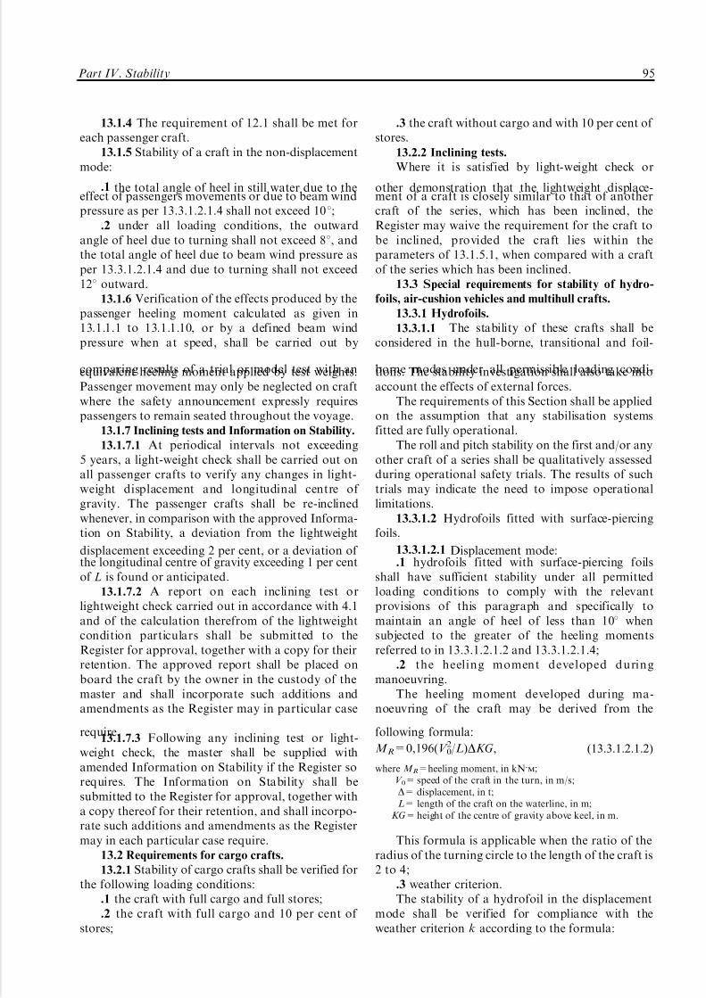
5/12/2018 High Speed Craft Rusa - slidepdf.com
http://slidepdf.com/reader/full/high-speed-craft-rusa 96/167
13.1.4 The requirement of 12.1 shall be met foreach passenger craft.
13.1.5 Stability of a craft in the non-displacementmode:
.1 the total angle of heel in still water due to theeffect of passengers movements or due to beam windpressure as per 13.3.1.2.1.4 shall not exceed 108;
.2 under all loading conditions, the outwardangle of heel due to turning shall not exceed 88, andthe total angle of heel due to beam wind pressure asper 13.3.1.2.1.4 and due to turning shall not exceed128 outward.
13.1.6 Verification of the effects produced by thepassenger heeling moment calculated as given in13.1.1.1 to 13.1.1.10, or by a defined beam windpressure when at speed, shall be carried out by
comparing results of a trial or model test with anequivalent heeling moment applied by test weights.Passenger movement may only be neglected on craftwhere the safety announcement expressly requirespassengers to remain seated throughout the voyage.
13.1.7 Inclining tests and Information on Stability.
13.1.7.1 At periodical intervals not exceeding5 years, a light-weight check shall be carried out onall passenger crafts to verify any changes in light-weight displacement and longitudinal centre of gravity. The passenger crafts shall be re-inclinedwhenever, in comparison with the approved Informa-tion on Stability, a deviation from the lightweight
displacement exceeding 2 per cent, or a deviation of the longitudinal centre of gravity exceeding 1 per centof L is found or anticipated.
13.1.7.2 A report on each inclining test orlightweight check carried out in accordance with 4.1and of the calculation therefrom of the lightweightcondition particulars shall be submitted to theRegister for approval, together with a copy for theirretention. The approved report shall be placed onboard the craft by the owner in the custody of themaster and shall incorporate such additions andamendments as the Register may in particular case
require.13.1.7.3 Following any inclining test or light-
weight check, the master shall be supplied withamended Information on Stability if the Register sorequires. The Information on Stability shall besubmitted to the Register for approval, together witha copy thereof for their retention, and shall incorpo-rate such additions and amendments as the Registermay in each particular case require.
13.2 Requirements for cargo crafts.
13.2.1 Stability of cargo crafts shall be verified forthe following loading conditions:
.1 the craft with full cargo and full stores;
.2 the craft with full cargo and 10 per cent of stores;
.3 the craft without cargo and with 10 per cent of stores.
13.2.2 Inclining tests.
Where it is satisfied by light-weight check or
other demonstration that the lightweight displace-ment of a craft is closely similar to that of anothercraft of the series, which has been inclined, theRegister may waive the requirement for the craft tobe inclined, provided the craft lies within theparameters of 13.1.5.1, when compared with a craftof the series which has been inclined.
13.3 Special requirements for stability of hydro-
foils, air-cushion vehicles and multihull crafts.
13.3.1 Hydrofoils.
13.3.1.1 The stability of these crafts shall beconsidered in the hull-borne, transitional and foil-
borne modes under all permissible loading condi-tions. The stability investigation shall also take intoaccount the effects of external forces.
The requirements of this Section shall be appliedon the assumption that any stabilisation systemsfitted are fully operational.
The roll and pitch stability on the first and/or anyother craft of a series shall be qualitatively assessedduring operational safety trials. The results of suchtrials may indicate the need to impose operationallimitations.
13.3.1.2 Hydrofoils fitted with surface-piercingfoils.
13.3.1.2.1 Displacement mode:.1 hydrofoils fitted with surface-piercing foils
shall have sufficient stability under all permittedloading conditions to comply with the relevantprovisions of this paragraph and specifically tomaintain an angle of heel of less than 108 whensubjected to the greater of the heeling momentsreferred to in 13.3.1.2.1.2 and 13.3.1.2.1.4;
.2 the heeling moment developed duringmanoeuvring.
The heeling moment developed during ma-noeuvring of the craft may be derived from the
following formula:
M R=0,196(V 02/L)DKG, (13.3.1.2.1.2)
where M R=heeling moment, in kN/M;
V 0= speed of the craft in the turn, in m/s;D= displacement, in t;L= length of the craft on the waterline, in m;
KG= height of the centre of gravity above keel, in m.
This formula is applicable when the ratio of theradius of the turning circle to the length of the craft is2 to 4;
.3 weather criterion.The stability of a hydrofoil in the displacement
mode shall be verified for compliance with theweather criterion k according to the formula:
Part IV. Stability 95

5/12/2018 High Speed Craft Rusa - slidepdf.com
http://slidepdf.com/reader/full/high-speed-craft-rusa 97/167
K=M c/M v51, (13.3.1.2.1.3)
where M c=minimum capsizing moment as determined whenaccount is taken of rolling;
M v= dynamically applied heeling moment due to the windpressure;
.4 heeling moment due to wind pressure.Heeling moment due to wind pressure M v, in kN/m,
is determined by the formula:
M v=0,001 pvAvZ , (13.3.1.2.1.4)
where Pv = wind pressure, in N/m2, = 750 (V w/26)2;Av = windage area, in m2, including the projections of the
lateral surfaces of the hull, superstructure and variousstructures above the waterline;
Z = windage area lever, in m, = the vertical distance to thegeometrical centre of windage area from the waterline;
V w = wind speed corresponding to the worst intended condi-tions, in m/s.
The value of the heeling moment is taken asconstant during the whole period of heeling;
.5 evaluation of the minimum capsizing momentM c in the displacement mode.
The minimum capsizing moment is determinedfrom the static or dynamic stability curves takingrolling into account;
.5.1 when the static stability curve is used, M c isdetermined by equating the area under the curves of capsizing and righting moments (or levers) takingrolling into account as indicated by Fig. 13.3.1.2.1.5-1,where yr is the amplitude of rolling and MK is a line
drawn parallel to the abscissa axis such that theshaded areas S 1 and S 2 are equal.
M c=OM, if the scale of ordinates representsmoments;
M c=OM6displacement, if the scale of ordinatesrepresents levers;
.5.2 when the dynamic stability curve is used, firstan auxiliary point A shall be determined. For thispurpose the amplitude of rolling is plotted to theright along the abscissa axis and point A' is found(see Fig. 13.3.1.2.5-2). A line AA' is drawn parallel tothe abscissa axis equal to the double amplitude of
heeling (AA'=2yr) and the required auxiliary point Ais found. A tangent AC to the dynamic stability curveis drawn. From the point A the line AB is drawnparallel to the abscissa axis and equal to 1 radian
(57,38). From the point B a perpendicular is drawn tointersect the tangent in the point E. The distance BEis equal to the capsizing moment if measured alongthe ordinate axis of the dynamic stability curve. If,however, the dynamic stability levers are plottedalong this axis, BE is then the capsizing lever, and inthis case the capsizing moment M c is determined bymultiplication of ordinate BE, in metres, by thecorresponding displacement in tonnes:
m S=9,81Dwe, kN/m; (13.3.1.2.1.5.2)
.5.3 the amplitude of rolling Yr shall be
determined by means of model and full-scale testsin irregular seas as a maximum amplitude of 50oscillations of a craft travelling at 908 to the wavedirection in sea state for the worst design condition.
If such data are lacking the amplitude of rolling isassumed to be equal to 158;
.5.4 the effectiveness of stability curves shall belimited to the angle of flooding.
13.3.1.2.2 Transitional and foil-borne modes:.1 the stability in the transient and foil-borne
modes shall be verified for all cases of loading for theintended service of the craft. Under all weather
conditions up to the worst intended conditions, thetime to pass from the displacement mode to the foil-borne mode and vice versa shall be minimized unlessit is demonstrated that no substantial reduction of stability occurs during the transition;
.2 stability in the transitional and foil-bornemodes may be determined either by calculation or onthe basis of data obtained from model experimentsand shall be verified by full-scale tests by impositionof a series of known heeling moments by off-centreballast weights, and recording the angles of heelproduced by these moments. When taken in thedisplacement, take-off and steady foil-borne andsettling to the displacement mode, these results willprovide an indication of the values of the stability in
yrS 2
S 1
K
Fig. 13.3.1.2.1.5-1
Moment or lever
, (radian)
r r
Fig. 13.3.1.2.5-2
96 Rules for the Classification and Construction of High-Speed Craft
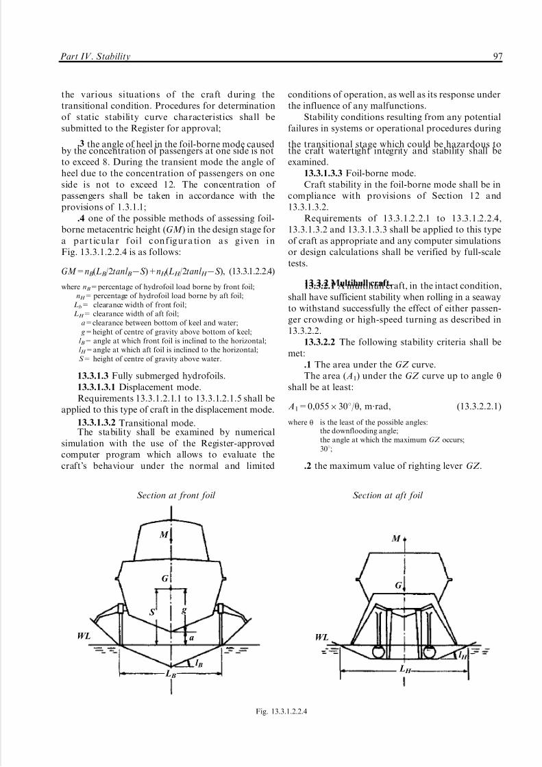
5/12/2018 High Speed Craft Rusa - slidepdf.com
http://slidepdf.com/reader/full/high-speed-craft-rusa 98/167
the various situations of the craft during thetransitional condition. Procedures for determinationof static stability curve characteristics shall besubmitted to the Register for approval;
.3 the angle of heel in the foil-borne mode causedby the concentration of passengers at one side is notto exceed 8. During the transient mode the angle of heel due to the concentration of passengers on oneside is not to exceed 12. The concentration of passengers shall be taken in accordance with theprovisions of 1.3.1.1;
.4 one of the possible methods of assessing foil-borne metacentric height (GM ) in the design stage fora p ar t ic u la r f oi l c on f ig ur a ti on a s g i ve n i nFig. 13.3.1.2.2.4 is as follows:
GM=nB(LB/2tanl B7S )+nH (LH /2tanl H 7S ), (13.3.1.2.2.4)
where nB=percentage of hydrofoil load borne by front foil;nH = percentage of hydrofoil load borne by aft foil;
Lb= clearance width of front foil;LH = clearance width of aft foil;
a=clearance between bottom of keel and water; g=height of centre of gravity above bottom of keel;l B= angle at which front foil is inclined to the horizontal;l H =angle at which aft foil is inclined to the horizontal;S = height of centre of gravity above water.
13.3.1.3 Fully submerged hydrofoils.13.3.1.3.1 Displacement mode.Requirements 13.3.1.2.1.1 to 13.3.1.2.1.5 shall be
applied to this type of craft in the displacement mode.
13.3.1.3.2 Transitional mode.The stability shall be examined by numerical
simulation with the use of the Register-approvedcomputer program which allows to evaluate thecraft's behaviour under the normal and limited
conditions of operation, as well as its response underthe influence of any malfunctions.
Stability conditions resulting from any potentialfailures in systems or operational procedures during
the transitional stage which could be hazardous tothe craft watertight integrity and stability shall beexamined.
13.3.1.3.3 Foil-borne mode.Craft stability in the foil-borne mode shall be in
compliance with provisions of Section 12 and13.3.1.3.2.
Requirements of 13.3.1.2.2.1 to 13.3.1.2.2.4,13.3.1.3.2 and 13.3.1.3.3 shall be applied to this typeof craft as appropriate and any computer simulationsor design calculations shall be verified by full-scaletests.
13.3.2 Multihull craft.13.3.2.1 A multihull craft, in the intact condition,shall have sufficient stability when rolling in a seawayto withstand successfully the effect of either passen-ger crowding or high-speed turning as described in13.3.2.2.
13.3.2.2 The following stability criteria shall bemet:
.1 The area under the GZ curve.The area (A1) under the GZ curve up to angle y
shall be at least:
A1=0,0556308/y, m´rad, (13.3.2.2.1)
where y is the least of the possible angles:the downflooding angle;the angle at which the maximum GZ occurs;308;
.2 the maximum value of righting lever GZ .
Part IV. Stability 97
M M
G G
S g
a
l Bl H
L H L B
WL WL
Section at front foil Section at aft foil
Fig. 13.3.1.2.2.4

5/12/2018 High Speed Craft Rusa - slidepdf.com
http://slidepdf.com/reader/full/high-speed-craft-rusa 99/167
The maximum GZ value shall occur at an angleof at least 108;
.3 heeling due to wind.The wind heeling lever shall be assumed constant
at all angles of inclination and shall be calculated asfollows:
HL1=Pi AZ 9800D , in m,
(13.3.2.3.3)
HL2=1,5HL1 , in m, (see Fig. 13.3.2.2),
where Pi =wind pressure, in N/m2, to be obtained from theformula:
Pi = 500 (V w/26)2;
V w = wind speed corresponding to the worst intended condi-tions, in m/s;
A= projected lateral area of the portion of the craft abovethe lightest service waterline, in m2;
Z = vertical distance from the centre of A to a point one half
the lightest service draught, in m;D= displacement, in t;
.4 heeling due to passenger crowding or high-speed turning.
Heeling lever due to the crowding of passengerson one side of the craft or to high-speed turning,whichever is the greater, shall be considered incombination with the heeling lever HL2 due to wind(regarding the gust);
.4.1 heeling due to passenger crowding.When calculating the heel a heeling lever due to
passenger crowding shall be determined. The calcula-
tion shall be made with regard to provisions of 13.1.1and 3.1.6 to 3.1.9, Part IV "Stability" of the Rules forthe Classification and Construction of Sea-GoingShips;
.4.2 heeling due to high-speed turning.When calculating the heel a heeling lever due to
high-speed turning shall be determined using thefollowing formula:
TL= 1 g
V 02
R(KG7d/2), (13.3.2.2.4.2)
where TL=turning lever, in m;V 0= speed of the craft in the turn, in m/s;R= turning radius, in m;
KG= height of vertical centre of gravity above keel, in m;d =mean draught, in m; g=acceleration due to gravity.
Alternatively, another method of assessment maybe employed as provided for 3.1.1;
.5 rolling in waves (see Fig. 13.3.2.2).The effect of rolling in a seaway upon the craft
stability shall be demonstrated mathematically. Indoing so, the residual area (A2) under the GZ curve,i. e. beyond the angle of heel yh , shall be at least equalto 0,028 m´rad up to the angle of rolling yr. In theabsence of model tests results or other data yr shall betaken as 158 or as an angle of (yd 7yh), whichever isless.
The determination of yr from the model test orother data shall be carried out using the procedurefor determining yr given in 13.3.1.2.1.5.3;
.6 for the purpose of intact stability calculationsand application of Fig. 13.3.2.2, the following heelinglevers shall be used:
.6.1 wind heeling lever (including gusting effect) ± HL2;
.6.2 total heeling lever equal to the sum of heelinglever due to wind (+ gusting) and heeling lever due
A1
HL2
yh
yh yhyd
yd yd
yr yr
ym 308
not greater than 108
HTL HTL
A2 A2
Fig. 13.3.2.2
HL2 = heeling lever due to wind + gusting;HTL = heeling lever due to wind + gusting + (passenger crowding or turning), whichever is the greater;yh = angle of heel due to heeling moment with lever HL2 or HTL;
yr = angle of roll;yd = angle of downflooding;ym = angle of maximum GZ.
98 Rules for the Classification and Construction of High-Speed Craft

5/12/2018 High Speed Craft Rusa - slidepdf.com
http://slidepdf.com/reader/full/high-speed-craft-rusa 100/167
to either passenger crowding or turning, whichever isthe greater.
The angle of heel due to the wind heeling lever(HL2) shall not exceed 108.
13.3.3 Air-cushion vehicles.13.3.3.1 These requirements apply to air-cushion
vehicles of all types.13.3.3.2 Air-cushion vehicles in the displacement
mode are covered by the requirements of 13.3.1.2.1.2.The angle of heel due to the combined effect of turning and passenger crowding shall be determinedexperimentally.
13.3.3.3 Stability of air-cushion vehicles in thetransitional mode shall be such that the inclination of the craft from the horizontal in any direction will notexceed 88 under all possible loading conditions and
passenger movements as may occur.13.3.3.4 Stability of air-cushion vehicles in theoperational and transitional modes shall meet therequirements of 13.3.1.2.2. The total angle of heel dueto passenger crowding and wind pressure or due topassenger crowding and turning shall be determinedon the basis of model tests of the designed craft orprototype craft.
The total angle of heel due to passenger crowdingand turning shall be determined experimentally in amore accurate way during delivery trials of the full-scale craft.
13.3.3.5 Where an air-cushion vehicle shall go to
a shore which is not protected against waves, it shallbe demonstrated to the Register that the craftstability is sufficient when it passes the tidal area
under the worst permissible conditions or otherconditions indicated in the Classification Certificate.These proofs shall be confirmed during delivery trialsof the first or any other craft of the series as indicated
by the Register.13.3.3.6 The following structural requirements
shall be met to ensure stability of an air-cushionvehicle:
.1 the shape of the rigid hull in the forward endshall provide the hydrodynamic righting moment inwater landing with a bow trim in still water and in aseaway. The hull slope angle shall be not lessthan 128;
.2 for air-cushion vehicles fitted with flexibleskirts it shall be demonstrated that flexible skirts willnot lose stability in the modes allowed by the
operational manual and in all possible loadingconditions. The height of flexible skirts and hullstructure shall be such that in the cushion-bornemode the contact of the main hull with thesupporting surface (water, land) can occur at a heelangle not less than 98 and trim 38. The opening angleof flexible skirt shall be not less than 308;
.3 in designs where periodic use of cushiondeformation is employed as a means of assistingcraft control, or periodic use of cushion air exhaust-ing to atmosphere for purposes of craft manoeuvring,the effects upon cushion-borne stability shall bedetermined, and the limitations on the use by virtue
of weather conditions, mode and loading conditionof the craft shall be established. These limitationsshall be indicated in Information on Stability.
Part IV. Stability 99
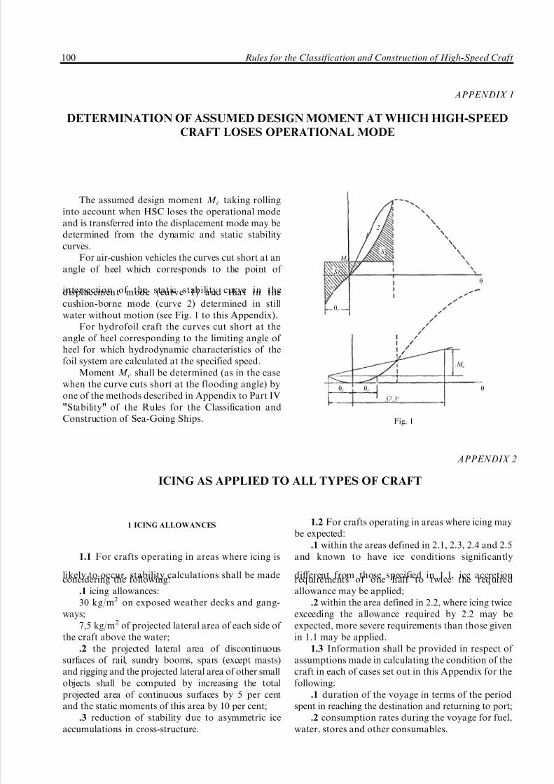
5/12/2018 High Speed Craft Rusa - slidepdf.com
http://slidepdf.com/reader/full/high-speed-craft-rusa 101/167
The assumed design moment M c taking rollinginto account when HSC loses the operational modeand is transferred into the displacement mode may bedetermined from the dynamic and static stabilitycurves.
For air-cushion vehicles the curves cut short at anangle of heel which corresponds to the point of
intersection of the static stability curve in thedisplacement mode (curve 1) and that in thecushion-borne mode (curve 2) determined in stillwater without motion (see Fig. 1 to this Appendix).
For hydrofoil craft the curves cut short at theangle of heel corresponding to the limiting angle of heel for which hydrodynamic characteristics of thefoil system are calculated at the specified speed.
Moment M c shall be determined (as in the casewhen the curve cuts short at the flooding angle) byone of the methods described in Appendix to Part IV"Stability" of the Rules for the Classification andConstruction of Sea-Going Ships.
APPENDIX 1
DETERMINATION OF ASSUMED DESIGN MOMENT AT WHICH HIGH-SPEED
CRAFT LOSES OPERATIONAL MODE
2
1
S 2 M c
S 1
y
yr
M c
yr yr y
57,38
Fig. 1
APPENDIX 2
ICING AS APPLIED TO ALL TYPES OF CRAFT
1 ICING ALLOWANCES
1.1 For crafts operating in areas where icing is
likely to occur, stability calculations shall be madeconcidering the following:.1 icing allowances:30 kg/m2 on exposed weather decks and gang-
ways;7,5 kg/m2 of projected lateral area of each side of
the craft above the water;.2 the projected lateral area of discontinuous
surfaces of rail, sundry booms, spars (except masts)and rigging and the projected lateral area of other smallobjects shall be computed by increasing the totalprojected area of continuous surfaces by 5 per centand the static moments of this area by 10 per cent;
.3 reduction of stability due to asymmetric iceaccumulations in cross-structure.
1.2 For crafts operating in areas where icing maybe expected:
.1 within the areas defined in 2.1, 2.3, 2.4 and 2.5and known to have ice conditions significantly
different from those specified in 1.1, ice accretionrequirements of one half to twice the requiredallowance may be applied;
.2 within the area defined in 2.2, where icing twiceexceeding the allowance required by 2.2 may beexpected, more severe requirements than those givenin 1.1 may be applied.
1.3 Information shall be provided in respect of assumptions made in calculating the condition of thecraft in each of cases set out in this Appendix for thefollowing:
.1 duration of the voyage in terms of the periodspent in reaching the destination and returning to port;
.2 consumption rates during the voyage for fuel,water, stores and other consumables.
100 Rules for the Classification and Construction of High-Speed Craft

5/12/2018 High Speed Craft Rusa - slidepdf.com
http://slidepdf.com/reader/full/high-speed-craft-rusa 102/167
2 AREAS OF ICING CONDITIONS
2.1 In the application of 1, the following icing
areas shall be considered:.1 the area north of latitude 65830'N, between
longitude 288W and the west coast of Iceland; northof the north coast of Iceland; north of the rhumb linerunning from latitude 668N, longitude 158W tolatitude 73830'N, longitude 158E, north of latitude73830'N, between longitude 158E and 358E, and eastof longitude 358E, as well as north of latitude 568N inthe Baltic Sea;
.2 the area north of latitude 438N bounded in thewest by the North American coast and the east by therhumb line running from latitude 438N, longitude
488W to latitude 638N, longitude 288W and thencealong longitude 288W;
.3 all sea areas north of the North Americancontinent, west of the areas defined in 2.1 and 2.2 of this paragraph;
.4 the Bering and Okhotsk Seas and the Tatary
Straight in winter;.5 south of latitude 608S.The chart to illustrate the areas is attached.
3 GENERAL REQUIREMENTS
3.1 Craft intended for operation in areas whereicing is likely to occur shall be:
.1 designed to minimize the accretion of ice;
.2 equipped with means for ice removing.
LEGEND
Full icing allowanceis to be applied.
Craft operating in this areahave been subjected on occasionto icing twice exceedingthe indicated full icing allowance.
A
Chart of Areas of Icing Conditions
The Okhotsk
SeaThe Tatary
Straight
The Bering
Sea
Part IV. Stability 101

5/12/2018 High Speed Craft Rusa - slidepdf.com
http://slidepdf.com/reader/full/high-speed-craft-rusa 103/167
1 GENERAL
1.1 Scope of application.
The requirements of Sections 1, 2, 3 of this Part aremandatory for high-speed crafts of all types referred toin Part I "Classification" of the present Rules.
The requirements of Section 4 of this Part applyto crafts referred to in 1.1.1 and 1.1.2, "General" of the present Rules.
1.2 Definitions and explanations.
Definitions and explanations relating to generalterminology are given in Part I "Classification" of the
present Rules and in Part V "Subdivision" of Rulesfor the Classification and Construction of Sea-GoingShips.
1.3 Scope of technical supervision.
For every craft meeting the requirements of thisPart, the Register carries out:
.1 verification of structural arrangements takento ensure subdivision of the craft with the require-ments of 2.2 of Rules for Safety of DynamicallySupported Craft (1990 edition), Part III "Equipment,Arrangements and Outfit" and Part VIII "Systemsand Piping" of the present Rules;
.2 consideration and approval of Information on
Damaged Trim and Stability;.3 verification of correct assignment and marking
of the design waterline.1.4 General technical requirements.
General technical requirements given in 1.4.4 to1.4.8 and 1.4.10, Part V "Subdivision" of the Rulesfor the Classification and Construction of Sea-GoingShips apply to HSC of all types.
2 INTACT BUOYANCY
2.1 All crafts shall have a sufficient reserve of buoyancy at the design waterline to meet the intactand damage stability requirements of this chapter. Acraft in the displacement mode at a draught to thedesign waterline shall have at least 100 per centreserve of buoyancy. The Register may require alarger reserve of buoyancy to permit the craft tooperate in any of its intended modes.
2.2 The reserve of buoyancy shall be calculatedby including only those compartments which are:
.1 watertight and situated below the watertightdeck (or an equivalent structure);
.2 watertight or weathertight and situated abovethe watertight deck (or an equivalent structure);
.3 accepted as having scantlings and arrange-ments adequate to maintain their watertight integrity.
In considering the stability after damage, floodingshall be assumed to occur until limited by watertightboundaries in the equilibrium condition, and weather-tight boundaries in intermediate stages of flooding andwithin the range of positive righting lever required tosatisfy the residual stability requirements.
2.3 Arrangements for checking the watertight orweatherhight integrity of compartments referred to in2.2 shall be provided in accordance with Part II"Hull" of the Rules for the Classification and
Construction of Sea-Going Ships.2.4 Where entry of water into structures abovethe watertight deck defined in 2.2.1 will significantlyinfluence the craft stability and buoyancy, suchstructures shall be:
.1 of adequate strength to maintain the weather-tight integrity and fitted with weathertight closingappliances; or
.2 provided with adequate drainage arrange-ments; or
.3 an equivalent combination of both.2.5 The means of closing of openings in
structures bounding weathertight compartmentsare
shall be such as to maintain weathertight integrity of the compartments in all operational conditions.
2.6 Opening in watertight divisions.
2.6.1 The number of doors in watertight bulk-heads shall be reduced to the minimum compatiblewith the design and proper working of the craft, andall such doors shall be closed prior to departure of thecraft from the berth.
2.6.2 Doors in watertight bulkheads may behinged or sliding. They shall be shown by suitabletesting to be capable of maintaining the watertightintegrity of the bulkhead. Such testing shall be
carried out for both sides of the door and shall applya pressure head 10 per cent greater than thatdetermined from the minimum permissible height of the downflooding opening. Testing may be carriedout either before or after the door is fitted into thecraft but where shore testing is adopted, satisfactoryinstallation on the craft shall be verified by inspectionand hose testing.
2.6.3 Type approval may be accepted in lieu of testing individual doors, provided the approvalprocess includes pressure testing to a head equal to,or greater than, the required head (refer to 2.6.2).
2.6.4 All watertight doors shall be capable of being operated when the craft is inclined up to 158,and shall be fitted with means of indication in the
PART V. RESERVE OF BUOYANCY AND SUBDIVISION
102 Rules for the Classification and Construction of High-Speed Craft

5/12/2018 High Speed Craft Rusa - slidepdf.com
http://slidepdf.com/reader/full/high-speed-craft-rusa 104/167
operating compartment showing whether they areopen or closed. All such doors shall be capable of being opened and closed locally from each side of thebulkhead.
2.6.5 Watertight doors shall remain closed whenthe craft is at sea, except that they may be opened foraccess. A notice shall be attached to each door to theeffect that it shall not be left open.
2.6.6 Watertight doors shall be capable of beingclosed by remote control from the operating com-partment in not less than 20 s and not more than 40 s,and shall be provided with an audible alarm, distinctfrom other alarms in the area, which shall sound forat least 5 s but no more than 10 s before the doorsbegin to move whenever the door is closed remotelyby power, and continue sounding until the door is
completely closed. The power, control and indicatorsshall be operable in the event of main power failure.In passenger areas and in areas where the ambientnoise exceeds 85 dB(A) the audible alarm shall besupplemented by an intermittent visual signal at thedoor. If the Register is satisfied that hinged doors areessential for safe work of the craft, such watertightdoors having only local control may be permitted forareas to which crew only have access, provided theyare fitted with remote indicators as required in 2.6.4.
2.6.7 Where pipes, scuppers, electric cables, etc.are carried through watertight divisions, the arrange-ments for creating a watertight penetration shall be of
a type, which has been prototype tested underhydrostatic pressure equal to or greater than thatrequired to be withstood for the actual location in thecraft in which they shall be installed. The testpressure shall be maintained for at least 30 min andthere shall be no leakage through the penetrationarrangement during this period. The test pressurehead shall be 10 per cent greater than that determinedfrom the minimum permissible height of a down-flooding opening. Watertight bulkhead penetrationswhich are effected by continuous welding do notrequire prototype testing. Valves on scuppers from
weathertight compartments, included in the stabilitycalculations, shall have arrangements for remoteclosing from the operating station.
2.6.8 Where a ventilation trunk forms part of awatertight boundary, the trunk shall be capable of withstanding the water pressure that may be presenttaking into account the maximum inclination angleof the damaged craft allowable during all stages of flooding.
2.7 Inner bow doors.
2.7.1 Where ro-ro craft are fitted with bowloading doors, an inner bow door shall be fittedabaft such openings, to restrict the extent of floodingin the event of failure of the outer closure. This innerbow door, where fitted, shall be:
.1 weathertight to the deck above, which deckshall itself be weathertight forward to the bowloading opening;
.2 so arranged as to preclude the possibility of a
bow loading door causing damage to it in the case of damage to, or detachment of, the bow loading door;
.3 forward of all positions on the vehicle deck inwhich vehicles are intended to be carried; and
.4 part of a boundary designed to preventflooding into the remainder of the craft.
2.7.2 A craft shall be exempted from therequirement 2.7.1 for such inner bow door whereone of the following applies.
2.7.2.1 The vehicle loading deck at the inner bowdoor position is above the design waterline by aheight more than the significant wave height corre-
sponding to the worst intended conditions.2.7.2.2 It can be demonstrated using model testsor mathematical simulations that when the craft isproceeding at a range of speeds up to the maximumattainable speed in the loaded condition at allheadings in long crested seas of the greatestsignificant wave height corresponding to the worstintended conditions, either:
.1 the bow loading door is not reached by waves; or
.2 having been tested with the bow loading dooropen to determine the maximum steady state volumeof water which accumulates, it can be shown by staticanalysis that, with the same volume of water on the
vehicle deck(s) the residual stability requirements aresatisfied. If the model tests or mathematical simula-tions are unable to show that the volume of wateraccumulated reaches a steady state, the craft shall beconsidered not to have satisfied the conditions of thisexemption.
Where mathematical simulations are employedthey shall already have been verified against full-scaleor model testing.
2.7.2.3 Bow loading openings lead to open ro-rospaces provided with guard-rails or having freeingports complying with 2.7.2.4.
2.7.2.4 The deck of the lowest ro-ro space abovethe design waterline is fitted on each side of the deckwith freeing ports evenly distributed along the sidesof the compartment. These shall either proven to beacceptable using tests according to 2.7.2.2 above orcomply with the following:
.1 A50,3l , (2.7.2.4.1)where A = the total area of freeing ports on each side of the deck,
in m2;l = the length of the compartment, in m;
.2 the craft shall maintain a residual freeboard tothe deck of the ro-ro space of at least 1 m in the worstcondition;
.3 such freeing ports shall be located within theheight of 0,6 m above the deck of the ro-ro space, and
Part V. Reserve of Buoyancy and Subdivision 103

5/12/2018 High Speed Craft Rusa - slidepdf.com
http://slidepdf.com/reader/full/high-speed-craft-rusa 105/167
the lower edge of the ports shall be within 0,02 mabove the deck of the ro-ro space; and
.4 such freeing ports shall be fitted with closingdevices or flaps to prevent water entering the deck of
the ro-ro space whilst allowing water which mayaccumulate on the deck of the ro-ro space to drain.
2.8 Other provisions for ro-ro craft.
2.8.1 All accesses to the ro-ro space that lead tospaces below the deck shall have a lowest point whichis not less than the height required from the testsconducted according to 2.7.2.2 or 3 m above thedesign waterline.
2.8.2 Where vehicle ramps are installed to giveaccess to spaces below the deck of the ro-ro space,their openings shall be capable of being closedweathertight to prevent ingress of water below.
2.8.3 Accesses in the ro-ro space that lead to spacesbelow the ro-ro deck and having a lowest point which isless than the height required from the tests conductedaccording to 2.7.2.2 or 3 m above the design waterlinemay be permitted provided they are watertight and areclosed before the craft leaves the berth on any voyageand remain closed until the craft is at its next berth.
2.8.4 Accesses referred to in 2.8.2 and 2.8.3 aboveshall be fitted with alarm indicators in the operatingcompartment.
2.8.5 Special category spaces and ro-ro spacesshall be patrolled or monitored by effective means,such as television surveillance, so that any movement
of vehicles in adverse weather conditions andunauthorised access by passengers thereto can bedetected whilst the craft is underway.
2.9 Indicators and surveillance.
2.9.1 Indicators.Indicators shall be provided in the operating
compartment for all shell doors, loading doors andother closing appliances, which, if left open or notproperly secured, could lead to major flooding in theintact or damaged conditions. The indicator systemshall be designed on the fail-safe principle and shallshow by visual alarms if the door is not fully closed
or if any of the securing arrangements are not inplace and fully locked, and by audible alarms if suchdoor or closing appliance becomes open or thesecuring arrangements become unsecured. The in-dicator panel in the operating compartment shall beequipped with a mode selection function "harbour/sea voyage" so arranged that an audible alarm isgiven in the operating compartment if the craft leavesharbour with the bow doors, inner doors, stern rampor any other side shell doors not closed or any closingdevice not in the correct position. The power supplyfor the indicator systems shall be independent of thepower supply for operating and securing the doors.
2.9.2 Television surveillance.Television surveillance and a water leakage
detection system shall be arranged to provide anindication to the operating compartment and to the
engine control station of any leakage through innerand outer bow doors, stern doors or any other shelldoors, which could lead to major flooding.
2.10 Integrity of superstructure.
2.10.1 Where entry of water into structures abovethe bulkhead deck would significantly influence thestability and buoyancy of the craft, such structuresshall be:
.1 of adequate strength to maintain the weather-tight integrity and fitted with weathertight closingappliances; or
.2 provided with adequate damage arrangements; or
.3 an equivalent combination of both measures.2.10.2 Weathertight superstructures and deck-houses located above the bulkhead deck shall have inthe outside boundaries means of closing openingswith sufficient strength such as to maintain weather-tight integrity in all damage conditions where thespace in question is not damaged. Furthermore, themeans of closing shall be such as to maintainweathertight integrity in all operational conditions.
2.11 Doors, windows, etc. in boundaries of
weathertight spaces.1
2.11.1 Strength of doors, windows, etc., and anyassociated frames and mullion in weathertight super-
structures and deckhouses shall be equivalent to thestrength of the structure in which they are fitted, i. e.they shall be weathertight and shall not leak or fail ata uniformly applied pressure to which the structurewhere they are fitted is designed.
2.11.2 For doors in weathertight superstructures,hose tests shall be carried out with a water pressure200 kN/m2 from the outside.
2.11.3 The height above the deck of sills todoorways leading to exposed decks shall be as highabove the deck as is reasonable and practicable,particularly those located in exposed positions. Such
sill heights shall not be less than 100 mm for doors toweathertight spaces on decks above the bulkheaddeck, and 250 mm elsewhere. For craft of 30 m inlength and under, sill heights may be reduced to themaximum which is consistent with the safe workingof the craft.
2.11.4 Windows shall not be permitted in theboundaries of:
special category spaces; orro-ro spaces; orbelow the bulkhead deck.If required by restrictions in the Permit to
Operate, forward facing windows, or windows which
1 For the purpose of this paragraph the word ªelsewhereº is applied to all the weathertight and watertight closures located on orbelow the datum.
104 Rules for the Classification and Construction of High-Speed Craft

5/12/2018 High Speed Craft Rusa - slidepdf.com
http://slidepdf.com/reader/full/high-speed-craft-rusa 106/167
may be submerged at any stage of flooding shall befitted with hinged or sliding storm shutters ready forimmediate use.
2.11.5 Side scuttles to spaces below the bulkhead
deck shall be fitted with efficient hinged deadlightsarranged inside so that they can be effectively closedand secured watertight.
2.11.6 No side scuttle shall be fitted in a positionso that its sill is below a line drawn parallel to andone metre above the design waterline.
2.12 Hatchways and other openings.1
2.12.1 Hatchways closed by weathertight covers.
The construction and the means for securing theweathertightness of cargo and other hatchways shallcomply with the following:
.1 coaming heights shall be not less than 100 mm
for hatches to weathertight spaces on decks above thebulkhead deck, and 250 mm elsewhere. For the craftof 30 m in length and under, coaming heights may bereduced to the maximum which is consistent with thesafe working of the craft;
.2 the height of these coamings may be reduced, orthe coamings omitted entirely, on condition that theRegister is satisfied that the safety of the ship is notthereby impaired in any sea conditions up to the worstintended conditions. Where coamings are provided,they shall be of substantial construction; and
.3 the arrangements for securing and maintainingweathertightness shall ensure that the tightness can
be maintained in any sea conditions up to the worstintended conditions.
2.12.2 Machinery space openings.
2.12.2.1 Machinery space openings shall be prop-erly framed and efficiently enclosed by casings of amplestrength. Where the casings are not protected by otherstructures, their strength shall be specially consideredby the Register. Access openings in such casings shallbe fitted with weathertight doors.
2.12.2.2 Height of sills and coamings shall be notless than 100 mm for openings to weathertight spaceson decks above the bulkhead deck, and not less than
380 mm elsewhere. For the craft of 30 m in lengthand under, these heights may be reduced to themaximum which is consistent with the safe workingof the craft.
2.12.2.3 Machinery space ventilator openingsshall comply with the requirements of 2.12.4.2.
2.12.3 Openings in exposed decks.
2.12.3.1 Manholes and flush scuttles on thebulkhead deck or within superstructures other thanenclosed superstructures shall be closed by substan-tial covers capable of being made watertight. Unlesssecured by closely spaces bolts, the covers shall bepermanently attached.
2.12.3.2 Service hatches to machinery, etc. may bearranged as flush hatches provided that the covers aresecured by closely spaced bolts, are kept closed at sea,and are equipped with arrangements for portable
guardrails.2.12.3.3 Openings in exposed decks leading to
spaces below the bulkhead deck or enclosed super-structures other than hatchways, machinery spaceopenings, manholes and flush scuttles shall beprotected by an enclosed superstructure, or by adeckhouse or companionway of equivalent strengthand weathertightness.
2.12.3.4 The height above the deck of sills to thedoorways in companionways shall not be less than100 mm for doors to weathertight spaces on decksabove the bulkhead deck, and 250 mm elsewhere. For
the craft of 30 m in length and under, sill heights maybe reduced to the maximum which is consistent withthe safe working of the craft.
2.12.4 Ventilators.
2.12.4.1 Ventilators to spaces below the bulkheaddeck or decks of enclosed superstructures shall havesubstantially constructed coamings efficiently con-nected to the deck. Coaming heights shall be not lessthan 100 mm for ventilators to weathertight spaceson decks above the bulkhead deck, and not less than380 mm elsewhere. For the craft of 30 m in lengthand under, coaming heights may be reduced to themaximum which is consistent with the safe working
of the craft.2.12.4.2 Ventilators the coamings of which extend
to more than one metre above the deck or which arefitted to decks above the bulkhead deck need not befitted with closing arrangements unless they faceforward or are specifically required by the Register,based on the construction and purpose of the craft.
2.12.4.3 Except as provided in 2.12.4.2, ventilatoropenings shall be provided with efficient weathertightclosing appliances.
2.12.4.4 Ventilator openings shall face aft orathwartships wherever practicable.
2.13 Scuppers, inlets and discharges.2.13.1 Discharges led through the shell either
from spaces below the bulkhead deck or from withinsuperstructures and deckhouses fitted above thebulkhead deck shall be fitted with efficient andaccessible means for preventing water from passinginboard. Normally each separate discharge shall haveone automatic non-return valve with a positive meansof closing it from a position above the bulkhead deck.Where, however, the vertical distance from the designwaterline to the inboard end of the discharge pipeexceeds 0,01L, the discharge may have two automaticnon-return valves without positive means of closing,
Part V. Reserve of Buoyancy and Subdivision 105
1 For the purpose of this paragraph the word ªelsewhereº is applied to all the weathertight and watertight closures located on orbelow the datum.

5/12/2018 High Speed Craft Rusa - slidepdf.com
http://slidepdf.com/reader/full/high-speed-craft-rusa 107/167
provided that the inboard valve is always accessiblefor examination under service conditions. Where thatvertical distance exceeds 0,02L, a single automaticnon-return valve without positive means of closing
may be accepted. The means for operating thepositive action valve shall be readily accessible andprovided with an indicator showing whether the valveis open or closed.
2.13.2 Valves on scuppers from weathertightcompartments included in the stability calculationsshall be operable from the operating compartment.
2.13.3 In manned machinery spaces, main andauxiliary sea inlets and discharges in connection withthe operation of machinery may be controlled locally.Such controls shall be readily accessible and shall beprovided with indicators showing whether the valves
are open or closed. In unmanned machinery spaces,main and auxiliary sea inlet and discharge controls inconnection with the operation of machinery shall be:
.1 located at least 50 per cent of the significantwave height corresponding to the worst operationalconditions and measured above the deepest damagewaterline with damages defined in accordance with4.3 of the present Part; or
.2 operable from the operating compartment.2.13.4 Scuppers leading from superstructures and
deckhouses not fitted with weathertight doors shallbe led overboard.
2.13.5 All shell fittings and the valves required by
the present Rules shall be of a suitable ductilematerial. Valves of ordinary cast iron or similarmaterial shall not be acceptable.
2.14 Air pipes.
2.14.1 Main storage tanks containing flammableliquids or tanks which can be pumped or filled fromthe sea shall have air pipes which do not terminate inenclosed spaces.
2.14.2 All air pipes extending to exposed decksshall have a height from the deck to the point wherewater may have access below of at least 300 mmwhere the deck is less than 0,05L above the design
waterline, and 150 mm on all other decks.2.14.3 Air pipes may discharge through the side
of the superstructure provided that this is at a heightof at least 0,02L above any waterline when the intactcraft is heeled to an angle of 158, or of at least 0,02L
above the highest waterline at all stages of flooding asdetermined by the damaged stability calculations,whichever is higher.
2.14.4 All air pipes shall be equipped withweathertight closing devices that close automatically.
2.15 Freeing ports.
2.15.1 Where bulwarks on weather decks formwells, provision shall be made for rapidly freeing thedecks of water and for draining them. The minimumfreeing port area A, in m2, on each side of the craft
for each well on the weather deck of the main hull(s)shall be:
.1 where the length of bulwark l in the well is20 m or less:
A =0,7 + 0,035l; (2.15.1.1)
.2 where l exceeds 20 m:
A = 0,07l , (2.15.1.2)
and, in no case, l need be taken as greater than0,7L.
If the bulwark is more than 1,2 m in averageheight, the required area shall be increased by0,004 square metres per metre of length of well foreach 0,1 metre difference in height. If the bulwark isless than 0,9 m in average height, the required area
shall be decreased by 0,004 square metres per metreof length of well for each 0,1 metre difference inheight.
2.15.2 Freeing ports shall be located within theheight of 0,6 m above the deck and the lower edgeshall be within 0,02 m above the deck.
2.15.3 All such openings in the bulwarks shall beprotected by rails or bars spaced approximately230 mm apart. If shutters are fitted to freeing ports,ample clearance shall be provided to prevent jam-ming. Hinges shall have pins or bearings of non-corrodible material. If shutters are fitted withsecuring appliances, these appliances shall be of
approved construction.2.15.4 A craft, having superstructures which are
open in front or both ends, shall comply with theprovisions of 4.2.11.1.
2.15.5 In a craft, having superstructures whichare open at the aft end, the minimum freeing portarea, in m2, shall be:
A = 0,3b, (2.15.5)
where b = the breadth of the craft at the exposed deck, in m.
2.15.6 Ro-ro craft fitted with bow loading open-
ings leading to open vehicle spaces shall comply withthe provisions of 2.7.
3 FREEBOARD
3.1 The freeboard for a craft in the displacementmode shall be assigned so that the requirementsregarding reserve of buoyancy and intact stability of the craft are met for the appropriate design waterline.
3.2 Based on the reserve of power necessary forcraft's motion in the operational mode, a greaterfreeboard than indicated in 3.1 may be assigned.
3.3 The design waterline shall be clearly andpermanently marked on the craft's outer sides at the
106 Rules for the Classification and Construction of High-Speed Craft

5/12/2018 High Speed Craft Rusa - slidepdf.com
http://slidepdf.com/reader/full/high-speed-craft-rusa 108/167
level of the load line mark described below. This andthe reference line described in 3.4.2 shall be recordedin the High-Speed Craft Safety Certificate. For craftwhere this is not practicable, e. g. amphibious air-
cushion vehicles fitted with peripheral skirts, defineddeck reference points shall be provided, from whichthe freeboard can be measured, and hence thedraughts obtained.
3.4 Load line mark.
3.4.1 The load line mark shall consist of a ring withan outside diameter of 300 mm and width of 25 mmwhich is intersected by a horizontal line of length450 mm and having a breadth of 25 mm, the upperedge of which passes through the centre of the ring. Thecentre of the ring shall be placed at the longitudinalcenter of floatation in the displacement mode and a
height corresponding to the design waterline.3.4.2 To assist in verifying the position of theload line mark, a reference line shall be marked onthe hull at the longitudinal centre of floatation by ahorizontal bar having a length of 300 mm and abreadth of 25 mm and having the upper edgecorresponding to the reference line.
3.4.3 Where practicable, the reference line shallbe related to the uppermost deck at side. Where thisis not possible, the position of the reference line shallbe defined from the underside of the keel at thelongitudinal centre of floatation.
3.4.4 The mark of the authority by whom the load
lines are assigned may be indicated alongside the loadline ring above the horizontal line which passes throughthe centre of the ring, or above and below it. This markshall consist of not more than four initials to identifythe authority's name, each measuring approximately115 mm in height, and 75 mm in width.
3.4.5 The ring, lines and letters shall be painted inwhite or yellow on a dark ground or in black on alight ground, and permanently marked. The marksshall be plainly visible.
3.5 Verification.
The High-Speed Craft Safety Certificate shall not
be delivered until the Register has verified that themarks are correctly and permanently indicated on thesides of the craft.
For air-cushion vehicles with flexible skirts andsimilar craft marking of the load line mark and loadlines are subject to special consideration by theRegister.
4 SUBDIVISION
4.1 General.
4.1.1 Stability and reserve of buoyancy under allservice conditions (taking no account of icing) shall
be sufficient for meeting the requirements for damagetrim and stability.
4.1.2 Requirements for subdivision are consid-ered satisfied if with damages referred to in 4.3,
compartments flooded in the worst possible positionof the hole and permeabilities determined in accor-dance with 4.2, trim and stability of the craft meet therequirements of 4.4.
4.1.3 Calculations confirming compliance withthe requirements of 4.4 shall be made for suchnumber of the worst service loading conditions asregards trim and stability, such location and extent of damage defined in 4.3 that it can be predicted withconfidence that in all other cases the damaged craftwill be in a better condition as regards trim andstability.
In doing so, account shall be taken of the actualconfiguration of damaged compartments, their per-meabilities, type of closing appliances, intermediatedecks, platforms, transverse and longitudinal bulk-heads and enclosures, watertightness of which is suchthat these constructions restrict totally or temporarilywater flow inside the craft.
Any damage of a lesser extent than thatpostulated in 4.3.1 to 4.3.4, as applicable, whichwould result in a more severe condition shall be alsoinvestigated. The shape of the damage shall beassumed to be a parallelepiped.
4.1.4 Calculations of damage trim and stability shall
be made for the craft in the displacement mode.4.1.5 Where the equalization time of the damaged
craft is not specified, the requirement of 3.4.1.7,Part V "Subdivision" of Rules for the Classificationand Construction of Sea-Going Ships shall beapplied.
4.1.6 Arrangements for equalization of thedamaged craft shall be self-acting and be approvedby the Register.
4.2 Permeabilities.
4.2.1 For the purpose of making damage stabilitycalculations the volume and surface permeabilities
shall be in general as follows:
4.2.2 Notwithstanding 4.2.1, permeability deter-mined by direct calculation shall be used where amore onerous condition results, and may be used
Part V. Reserve of Buoyancy and Subdivision 107
Spaces Permeability
Intended for cargo or storesAccommodationMachineryIntended for liquidsIntended for cargo vehiclesVoid spaces
609585
0 or 951
9095
1Whichever results in the more severe requirements.
T a b l e 4.2.1

5/12/2018 High Speed Craft Rusa - slidepdf.com
http://slidepdf.com/reader/full/high-speed-craft-rusa 109/167
where a less onerous condition results from thatprovided according to 4.2.1.
4.2.3 Use of low-density foam or other media toprovide buoyancy in void spaces may be permitted,
provided that satisfactory evidence is provided to theRegister that any such suggested medium is the mostsuitable alternative and:
.1 is of close-cell form if foam, or otherwiseimpervious to water absorption;
.2 is structurally stable under service conditions;
.3 is chemically inert in relation to structuralmaterials with which it is in contact or othersubstances with which the medium is likely to be incontact (see 2.1.10, Part VI "Fire Protection");
.4 properly secured in place and easily removablefor inspection of void spaces.
4.2.4 The Register may permit void bottomspaces to be fitted within the watertight envelope of the hull without the provision of a bilge system or airpipes provided that:
.1 the structure is capable of withstanding thepressure head after any of the damages required bythis section;
.2 when carrying out a damage stability calcula-tion in accordance with the requirements of thissection, any void space adjacent to the damaged zoneshall be included in the calculation and the criteria of damage trim and stability shall be complied with;
.3 the means by which water has leaked into the
void space shall be removed shall be included in thecraft operating manual; and
.4 adequate ventilation is provided for inspectionof the space under consideration.
.5 the space filled with a low-density foam ormodular buoyancy elements, as well as any space notfitted with a venting system are considered as a voidspace for the purpose of this paragraph providedsuch foam or modular buoyancy elements fullycomply with 4.2.3.
4.3 Extent of damages.
All possible damages shall be assumed in damagetrim and stability calculations anywhere on theperiphery of the craft.
4.3.1 Extent of side damage.The following side damages shall be assumed
anywhere on the periphery of the craft:.1 the longitudinal extent of damage shall be
0,75!1/3 or (3 m+0,225!1/3), or 11 m, whichever isthe least;
.2 the transverse extent of penetration into thecraft shall be 0,2!1/3. However, where the craft isfitted with inflated skirts or with non-buoyant sidestructures, the transverse extent of penetration shallbe at least 0,12!1/3 into the main buoyancy hull ortank structure; and
.3 the vertical extent of damage shall be taken forthe full vertical extent of the craft,where:!= volume of displacement corresponding to
the design waterline, in m3.The damage is supposed to have the shape of a
parallelepiped1. The parallelepiped inboard face at itsmid-length shall be tangential to the surface corre-sponding to the specified side damage (transverseextent of penetration) or otherwise touching in atleast two places, as shown in Fig. 4.3.1-1.
The side damage shall not transversely penetratea greater distance than the extent of 0,21/3 at the
corresponding design waterline, except where a lesserextent is assumed in accordance with 4.3.1.2 (seeFigs. 4.3.1-2 and 4.3.1-3).
If considering a multihull, the periphery of thecraft is considered to only be the surface of the shellencompassed by the outboard surface of the outer-most hull at any given section.
4.3.2 Extent of bow and stern damage.
4.3.2.1 The following extents of damage shall beapplied to bow and stern (see Fig. 4.3.2):
1 A parallelepiped is defined as "a solid contained by parallelograms" and a parallelogram is defined as "a four-sided rectilinear figurewhose opposite sides are parallel".
Transverse extent
of penetration CLTransverse extent Longitudinal
of p ene tration e xte nt
of damage
Fig. 4.3.1-1
108 Rules for the Classification and Construction of High-Speed Craft

5/12/2018 High Speed Craft Rusa - slidepdf.com
http://slidepdf.com/reader/full/high-speed-craft-rusa 110/167
.1 at the fore end, damage to the area defined as Abow in compliance with 7.4.1, Part III, "Arrange-ments, Equipment and Outfit", the aft limit of whichbeing a transverse vertical plane, provided that thisarea need not extend further aft from the forwardextremity of the craft's watertight envelope than thedistance defined in 4.3.1.1;
.2 at the aft end, damage to the area aft of atransverse vertical plane at a distance 0,21/3 forwardof the aft extremity of the watertight envelope of thehull.
4.3.2.2 Where the damage of a lesser extent thandefined in 4.3.2.1 may lead to grave consequences,the damage trim and stability calculations shall beperformed for such damage.
4.3.3 Extent of bottom damage in areas vulner-able to raking damage.
4.3.3.1 Application..1 Any part of the surface of the hull(s) is
considered to be vulnerable to raking damage if it isin contact with the water at 90 per cent of maximumspeed in still water, and it also lies below two planeswhich are perpendicular to the craft centreline planeand at heights as shown in Fig. 4.3.3.1.
For multihulls, individual hulls shall be consid-ered separately.
.2 Raking damage shall be assumed to occuralong any fore-and-aft line on the surface of the hull(s)between the keel and the upper limit defined in theFig. 4.3.3.1.
Part V. Reserve of Buoyancy and Subdivision 109
Transverse extent
of penetration
Design Damage of less thanwaterline maximum vertical extent
Damage penetration limited below
CL design waterline by a vertical line
Fig. 4.3.1-2
Transverse extent
of penetration Damage of less than
maximum vertical extent
Design
waterline
Damage penetration limited below
design waterline by a vertical line
CL
Fig. 4.3.1-3
Deck area = Abow
0,2!1/3 Transverse vertical planes
Fig. 4.3.2

5/12/2018 High Speed Craft Rusa - slidepdf.com
http://slidepdf.com/reader/full/high-speed-craft-rusa 111/167
.3 Damage shall not be applied at the same timeas that defined in 4.3.1 or 4.3.4.
4.3.3.2 Extents of damage.4.3.3.2.1 Two different longitudinal extents shall
be considered separately:.1 55 per cent of the length L, measured from the
most forward point of the underwater buoyantvolume of each hull; and
.2 a percentage of the length L, applied anywhere
in the length of the craft, equal to 35 per cent for acraft where L=50 m and over and equal to (L/2+10)per cent for a craft where L is less than 50 m.
4.3.3.2.2 Except as provided below, the penetra-tion normal to the shell shall be 0,04!1/3 or 0,5 m,whichever is the lesser, in association with a girthalong the shell equal to 0,1!1/3, where ! is thevolume of displacement corresponding to the designwaterline, in m3. However this penetration or girth isunder no circumstances to extend above the verticalextent of the vulnerable area as specified in 4.3.3.1.1.
4.3.3.2.3 The shape of damage shall be assumed
to be rectangular in the transverse plane as shown inFig. 4.3.3.2.3. The damage shall be assumed at aseries of sections within the defined longitudinalextent in accordance with Fig. 4.3.3.2.3, the mid-point of the damaged girth being maintained at aconstant distance from the centreline throughout thatlongitudinal extent.
4.3.4 Extent of bottom damage in areas not
vulnerable to raking damage.
4.3.4.1 Application.The requirements apply to all parts of the hull(s)
below the design waterline which are not defined asvulnerable to raking damage in 4.3.3.1. Damage shallnot be applied at the same time as that defined in4.3.1 or 4.3.3.
4.3.4.2 Extent.The following extent of damage shall be assumed:.1 the length of damage in the fore-and-aft
direction shall be 0,75!1/3 or (3 m + 0,225!1/3),or 11 m, whichever is the least;
.2 the athwartships girth of damage shall be
0,2!1/3
;.3 the depth of penetration normal to the shell
shall be 0,02!1/3
where:!=volume of displacement corresponding to
the design waterline, in m3..4 the shape of damage shall be assumed to be
rectangular in the plane of the shell of the craft, andrectangular in the transverse plane as shown inFig. 4.3.3.2.1.
4.3.5 In applying 4.3.3 and 4.3.4 to multihullcraft, an obstruction at or below the design waterlineof up to 7 m in width shall be considered indetermining the number of hulls damaged of anyone time. The requirement of 4.1.3 shall be applied.
This line is parallel Design waterlineto the design waterline
0,3T
T
The area is vulnerable
to raking damage 0,5L
L
Fig. 4.3.3.1T = maximum draught of the hull (each hull considered individually in case of multihulls) to the design waterline, excluding any
non-buoyant structure such as single plate skegs or solid metal appendages.
Penetration normal
to the shell
Limit of penetration
Girth along the shell
Fig. 4.3.3.2.3
110 Rules for the Classification and Construction of High-Speed Craft

5/12/2018 High Speed Craft Rusa - slidepdf.com
http://slidepdf.com/reader/full/high-speed-craft-rusa 112/167
4.3.6 Following any of the postulated damagesdetailed in 4.1.3 to 4.3.5, the craft in still water shallhave sufficient buoyancy and positive stability tosimultaneously ensure that:
.1 for all craft other than amphibious air-cushionvehicles, after flooding has ceased and a state of equilibrium has been reached, the final waterline isbelow the level of any opening through which furtherflooding could take place by at least 50 per cent of thesignificant wave height corresponding to the worstintended conditions;
.2 for amphibious air-cushion vehicles, afterflooding has ceased and a state of equilibrium hasbeen reached, the final waterline is below the level of any opening through which further flooding couldtake place by at least 25 per cent of the significant
wave height corresponding to the worst intendedconditions;.3 there is a positive freeboard from the damage
waterline to survival craft embarkation positions;.4 essential emergency equipment, emergency
radiostations, power supplies and public addresssystems needed for organizing the evacuation remainaccessible and operational;
.5 the residual stability of craft meets theappropriate criteria as laid out in 4.6 and 4.7according to Table 6.2.1, Part IV "Stability". Withinthe range of positive stability governed by the criteriaof 4.6 and 4.7, no unprotected opening shall be
submerged.4.3.7 Downflooding openings referred to in 4.3.6
shall include doors and hatches which are used fordamage control or evacuation procedures, but mayexclude those which are closed by means of weath-ertight doors and hatch covers and not used fordamage control or evacuation procedures.
4.4 Requirements for passenger crafts.
4.4.1 Following any of the postulated damagesdetailed in 4.3.1 to 4.3.5, in addition to satisfying therequirements of 4.3.6 and 4.3.7, the craft in still watershall have sufficient buoyancy and positive stability
to simultaneously ensure that:.1 the angle of inclination of the craft from the
horizontal does not normally exceed 108 in anydirection. However, where this is clearly impractic-able, angles of inclination up to 158 immediately afterdamage but reducing to 108 within 15 min shall bepermitted provided that efficient non-slip decksurfaces and suitable holding points, e. g., holes,bars, etc., are provided; and
.2 any flooding of passenger compartments orescape routes which might occur will not significantlyimpede the evacuation of passengers.
4.4.2 In addition to the requirements in 4.4.1,category B craft shall also satisfy the followingcriteria after sustaining raking damage of 100 per
cent of length L, having the girth and penetrationgiven in 4.3.3.2.2, to any part of the surface of thehull(s) defined in 4.3.3.2.1:
.1 the angle of inclination of the craft from the
horizontal shall not exceed 208 in the equilibriumcondition;
.2 the range of positive righting lever shall be atleast 158 in the equilibrium condition;
.3 the positive area under the righting levercurve shall be at least 0,015 m´rad in the equilibriumcondition;
.4 the requirements of 4.3.6.3 and 4.4.1.2 aresatisfied;
.5 in intermediate stages of flooding, the max-imum righting lever shall be at least 0,05 m and therange of positive righting lever shall be at least 7 8.
In complying with the above, the righting levercurve shall be terminated at the angle of down-flooding, and only one free surface need be assumed.
4.5 Requirements for cargo crafts.
Following any of the postulated damages de-tailed in 4.1.3, 4.3.1 to 4.3.5, in addition to satisfyingthe requirements of 4.3.6 and 4.3.7, the craft in stillwater shall have sufficient buoyancy and positivestability to simultaneously ensure that the angle of inclination of the craft from the horizontal does notnormally exceed 158 in any direction. However,where this is clearly impracticable, angles of inclina-tion up to 208 immediately after damage but reducing
to 158 within 15 min may be permitted provided thatefficient non-slip deck surfaces and suitable holdingpoints, e .g., holes, bars, etc., are provided.
4.6 Requirements for monohull crafts.
The stability required in the final condition afterdamage, and after equalization where provided, shallbe determined as specified in 4.6.1 to 4.6.4.
4.6.1 The positive residual righting lever curveshall have a minimum range of 158 beyond the angleof equilibrium. This range may be reduced to aminimum of 108, in the case where the area under therighting lever curve is that specified in 4.6.2, increased
by the ratio:15
range, (4.6.1)
where the range is expressed in degrees.
4.6.2 The area under righting lever curve shall beat least 0,015 m´rad, measured from the angle of equilibrium to the lesser of:
.1 angle at which progressive flooding occurs;
.2 278 measured from the upright.4.6.3 A residual righting lever GZ , in m, shall be
obtained within the range of positive stability, takinginto account the greatest of the following heelingmoments:
.1 the crowding of all passengers towards one side;
Part V. Reserve of Buoyancy and Subdivision 111
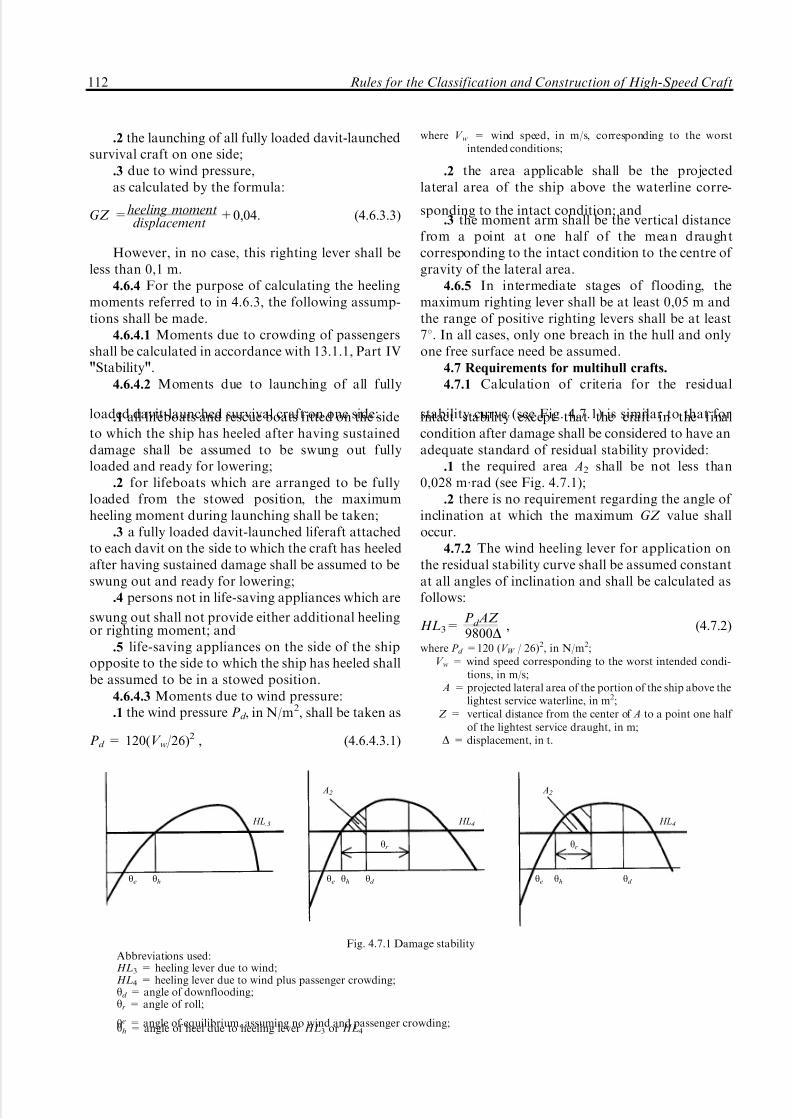
5/12/2018 High Speed Craft Rusa - slidepdf.com
http://slidepdf.com/reader/full/high-speed-craft-rusa 113/167
.2 the launching of all fully loaded davit-launchedsurvival craft on one side;
.3 due to wind pressure,as calculated by the formula:
GZ =heeling momentdisplacement
+0,04. (4.6.3.3)
However, in no case, this righting lever shall beless than 0,1 m.
4.6.4 For the purpose of calculating the heelingmoments referred to in 4.6.3, the following assump-tions shall be made.
4.6.4.1 Moments due to crowding of passengersshall be calculated in accordance with 13.1.1, Part IV"Stability".
4.6.4.2 Moments due to launching of all fully
loaded davit-launched survival craft on one side:.1 all lifeboats and rescue boats fitted on the sideto which the ship has heeled after having sustaineddamage shall be assumed to be swung out fullyloaded and ready for lowering;
.2 for lifeboats which are arranged to be fullyloaded from the stowed position, the maximumheeling moment during launching shall be taken;
.3 a fully loaded davit-launched liferaft attachedto each davit on the side to which the craft has heeledafter having sustained damage shall be assumed to beswung out and ready for lowering;
.4 persons not in life-saving appliances which are
swung out shall not provide either additional heelingor righting moment; and
.5 life-saving appliances on the side of the shipopposite to the side to which the ship has heeled shallbe assumed to be in a stowed position.
4.6.4.3 Moments due to wind pressure:.1 the wind pressure Pd , in N/m2, shall be taken as
Pd = 120(V w/26)2 , (4.6.4.3.1)
where V w = wind speed, in m/s, corresponding to the worstintended conditions;
.2 the area applicable shall be the projectedlateral area of the ship above the waterline corre-
sponding to the intact condition; and.3 the moment arm shall be the vertical distance
from a point at one half of the mean draughtcorresponding to the intact condition to the centre of gravity of the lateral area.
4.6.5 In intermediate stages of flooding, themaximum righting lever shall be at least 0,05 m andthe range of positive righting levers shall be at least78. In all cases, only one breach in the hull and onlyone free surface need be assumed.
4.7 Requirements for multihull crafts.
4.7.1 Calculation of criteria for the residual
stability curve (see Fig. 4.7.1) is similar to that forintact stability except that the craft in the finalcondition after damage shall be considered to have anadequate standard of residual stability provided:
.1 the required area A2 shall be not less than0,028 m´rad (see Fig. 4.7.1);
.2 there is no requirement regarding the angle of inclination at which the maximum GZ value shalloccur.
4.7.2 The wind heeling lever for application onthe residual stability curve shall be assumed constantat all angles of inclination and shall be calculated asfollows:
HL3=Pd AZ 9800D
, (4.7.2)
where P d =120 (V W / 26)2, in N/m2;V w = wind speed corresponding to the worst intended condi-
tions, in m/s;A = projected lateral area of the portion of the ship above the
lightest service waterline, in m2;Z = vertical distance from the center of A to a point one half
of the lightest service draught, in m;D = displacement, in t.
A2 A2
HL.3 HL4 HL4
yr yr
ye yh ye yh yd ye yh yd
Fig. 4.7.1 Damage stabilityAbbreviations used:HL3 = heeling lever due to wind;HL4 = heeling lever due to wind plus passenger crowding;yd = angle of downflooding;yr = angle of roll;
ye = angle of equilibrium, assuming no wind and passenger crowding;yh = angle of heel due to heeling lever HL3 or HL4
112 Rules for the Classification and Construction of High-Speed Craft

5/12/2018 High Speed Craft Rusa - slidepdf.com
http://slidepdf.com/reader/full/high-speed-craft-rusa 114/167
4.7.3 The same values of roll angle shall be usedas for the intact stability.
4.7.4 The residual stability curve shall terminateat the downflooding point. The area A2 shall there-
fore be truncated at the downflooding angle.4.7.5 The stability of the craft in the final
condition after damage shall be examined and shownto satisfy the criteria, when damaged as stipulated in4.3.
4.7.6 In the intermediate stages of flooding, themaximum righting lever shall be at least 0,05 m and
the range of positive righting lever shall be at least 78.In all cases, only one breach in the hull and only onefree surface need to be assumed.
4.7.7 In applying the heeling levers to the
damaged curves, the following shall be considered:heeling lever due to steady wind, HL3; andheeling lever due to steady wind plus heeling lever
due to passenger crowding HL4.4.7.8 The angle of heel due to steady wind shall
not exceed 158 for a passenger craft and 208 for acargo craft.
PART VI. FIRE PROTECTION
Part VI. Fire Protection 113
1 GENERAL
1.1 The requirements of Part VI "Fire Protec-tion" of the Rules for the Classification andConstruction of Sea-Going Ships (including refer-ences to the International Code for Application of Fire Test Procedures, IMO Resolution MSC.61(67))as far as reasonable and practicable, having regard tothe requirements given below, apply to HSC.
1.2 Definitions and explanations relating togeneral terminology are given in "General" of the
present Rules and Part VI "Fire Protection" of theRules for the Classification and Construction of Sea-Going Ships.
1.3 For the purpose of the present Rules thefollowing definitions have been additionally accepted.
S m o k e - t i g h t o r c a p a b l e o f p r e v e n -t i n g t h e p a s s a g e o f s m o k e means that adivision made of non-combustible or fire-restrictingmaterials is capable of preventing the passage of smoke at an ambient temperature.
A r e a s o f m a j o r f i r e h a z a r d referred toin Tables 2.5.2 and 2.6.2 by "A" include:
machinery spaces defined in 1.3, Part VII"Machinery Installations" of the Rules;ro-ro cargo spaces;spaces containing dangerous goods;special-category spaces;storerooms containing flammable liquids;galleys;shops of 50 m2 and more in area in which
flammable liquids are sold;main ducts directly connected with the above-
mentioned spaces.A r e a s o f m o d e r a t e f i r e h a z a r d re-
ferred to in Tables 2.5.2 and 2.6.2 by "B" include:
auxiliary machinery spaces defined in 1.4,Part VII "Machinery Installations" of the Rules;
stores containing packaged beverages with alco-hol content not exceeding 24 per cent by volume;
crew accommodation spaces with berths;service spaces;shops of less than 50 m2 in area, containing
limited quantity of flammable liquids for sale andhaving no separate storage area;
shops of more than 50 m2 in area which do notsell flammable liquids;
main ducts directly connected with the above-mentioned spaces.
A r e a s o f m i n o r f i r e h a z a r d referred to
in Tables 2.5.2 and 2.6.2 by "C" include:auxiliary machinery spaces defined in 1.5,
Part VII "Machinery Installations" of the presentRules;
cargo spaces;oil fuel tanks compartments;public spaces;tanks, void spaces and areas of minor or no fire
hazard;snack-bars;shops other than those arranged in the above-
mentioned areas;
corridors in passenger accommodation spacesand stairway enclosures;crew accomodation spaces without berths;main ducts directly connected with the above-
mentioned spaces.I M D G C o d e means the International Mari-
time Dangerous Goods (IMDG) Code in accordancewith Resolution MSC.205(81).
E v a c u a t i o n s t a t i o n s a n d e x t e r n a le s c a p e r o u t e s r e f e r r e d t o i n T a b l e s2.5.2 a n d 2.6.2 b y " E " , including the followingareas:
external stairs and open decks used for escape
routes;muster stations, internal and external;

5/12/2018 High Speed Craft Rusa - slidepdf.com
http://slidepdf.com/reader/full/high-speed-craft-rusa 115/167
open deck spaces and enclosed promenadesforming lifeboat and liferaft embarkation and low-ering stations;
craft side to the waterline in the lightest seagoing
condition, superstructure and deckhouse sides situ-ated below and adjacent to the liferaft and evacuationslide embarkation areas.
In relation to the classification of spaces in 1.3,the following additional criteria shall be applied:
.1 if a space is divided by partial bulkheads intotwo (or more) smaller areas such that they formenclosed spaces, then the enclosed spaces shall besurrounded by bulkheads and decks in accordancewith Tables 2.5.2 and 2.6.2, as applicable. However,if the separating bulkheads of such spaces are at least30 per cent open, then the spaces may be considered
as the same space;.2 cabinets having a deck area of less than 2 m 2
may be accepted as part of the space they serve,provided they have open ventilation to the space anddo not contain any material or equipment that couldbe a fire risk;
.3 where a space has the special characteristics of two or more space groupings, the structural fireprotection time of the divisions shall be the highestfor the space groupings concerned. For example, thestructural fire protection time of the divisions of emergency generator rooms shall be of the highestvalue for the space when the space is considered as
being a control station (D) and a machinery space (A).F i r e - r e s t r i c t i ng m a te r i a l s are materi-
als which have the following characteristics defined inaccordance with IMO Fire Test Procedures Code:
meet low flame spread characteristics;limit heat flux, due regard being paid to the risk
of furniture ignition in the compartment;have the limited rate of heat release, due regard
being paid to the risk of fire spread to an adjacentcompartment;
do not emit gas and smoke in quantities thatcould be dangerous to the occupants of the craft.
F i r e - r e s i s t i n g d i v i s i o n s are divisionsformed by bulkheads and decks and constructed of non-combustible or fire-restricting materials whichby insulation or inherent fire-resisting propertiessatisfy the following requirements:
they shall be suitably stiffened;they shall be constructed so as to be capable of
preventing the passage of smoke and flame up to theend of the appropriate standard fire test time;
where required, they shall maintain load-carryingcapabilities during the appropriate standard fire testtime;
they shall have thermal properties such that theaverage temperature on the unexposed side will notrise more than 139 8C above the original temperature,
nor will the temperature at any point, including any joint, rise more than 180 8C above the originaltemperature during the appropriate standard fire testtime;
specimens of the relevant bulkheads or decksshall be tested in accordance with IMO Fire TestProcedures Code to ensure that they meet the above-mentioned requirements.
O p e n s p a c e s r e f e r r e d t o i n T a b l e s2.5.2 a n d 2.6.2 b y " F " are spaces including openspaces which are not control stations of evacuationstations and external escape routes.
1.4 Enclosed spaces with low illumination level(cinemas, discotheques, and similar spaces) are notpermitted. Pantries which do not contain cookingfacilities with exposed heating surfaces may be
permitted. Galleys, if fitted, shall be in full compli-ance with the requirements of 2.1.9, Part VI "FireProtection"of the Rules for the Classification andConstruction of Sea-Going Ships.
1.5 The structural fire protection items shall beconsidered regarding the spread of heat and provi-sion of heat barriers.
1.6 On each craft fire control plans meeting therequirements of 1.4, Part VI ªFire Protectionº of theRules for the Classification and Construction of Sea-Going Ships shall be provided.
2 STRUCTURAL FIRE PROTECTION
2.1 Requirements for materials.
2.1.1 The requirements given below apply to allcraft, irrespective of construction materials of the hull.
2.1.2 The hull, superstructure, structural bulk-heads, decks, deckhouses and pillars shall be con-structed of approved non-combustible materialshaving the adequate structural characteristics. Theuse of other fire-restricting materials may be per-mitted provided the requirements of this Section are
met and the materials comply with the requirementsof IMO Fire Test Procedures Code.
Paragraph 2.1.2 does not apply to appendagessuch as propellers, air ducts to propellers, transmis-sion shafts, rudders and other control surfaces, struts,spars, flexible skirts, etc., which do not comprise partof the main structure of the craft.
2.1.3 All separating divisions, ceilings or linings if they are not fire-resisting, shall be of non-combus-tible or fire-restricting materials. Draught stops shallbe of non-combustible or fire-restricting materials.
2.1.4 Where insulation is installed in areas whereit could come into contact with any flammable fluidsor their vapours, its surface shall be impermeable tosuch flammable fluids or vapours.
114 Rules for the Classification and Construction of High-Speed Craft
5/12/2018 High Speed Craft Rusa - slidepdf.com
http://slidepdf.com/reader/full/high-speed-craft-rusa 116/167
The fire insulation in such spaces may be coveredby metal sheets (not perforated) or by vapour proof glass cloth sealed at joints.
2.1.5 Furniture in crew accommodation spaces
shall comply with the following requirements:all case furniture, e.g. desks, wardrobes, dressing
tables, bureaux and dressers shall be constructedentirely of approved non-combustible or fire-restrict-ing materials, except that a combustible veneer with acalorific value not exceeding 15 MJ/m2 may be usedon the exposed surface of such articles;
all furniture, such as chairs, sofas and tables,shall be constructed with frames of non-combustibleor fire-restricting materials;
all upholstered furniture shall be resistant toignition and flame spreading, as defined by IMO Fire
Test Procedures Code.2.1.6 All draperies, curtains and other suspendedtextile materials, bedding components and deck finishmaterials shall be of a type approved by the Registerbased on the positive results of standard tests inaccordance with IMO Fire Test Procedures Code.
2.1.7 Subject to 2.1.8 the following surfaces shall,as a minimum, be constructed of materials havinglow flame-spread characteristics:
.1 exposed surfaces of corridors, stairway en-closures, bulkheads (including windows), wall andceiling linings in all public, crew accommodation andservice spaces, control stations, internal muster and
evacuation stations;.2 surfaces in concealed and inaccessible areas in
corridors and stairway enclosures, public, service andcrew accommodation spaces, control stations andinternal muster and evacuation stations.
Paragraph 2.1.7 does not apply to partitions,windows and side scuttles made of glass which aredeemed to be non-combustible and to comply withthe requirements for low-flame spread surfaces or toitems and materials referred to in 2.1.51.
2.1.8 Any thermal or acoustic insulation materialshall be of non-combustible material, except when the
use of fire-restricting materials is permitted incompliance with the present Rules.
2.1.9 Surfaces referred to in 2.1.7.1 shall be of materials which, when exposed to fire, do not emitsmoke or toxic gases in excessive quantities as definedby IMO Fire Test Procedures Code.
2.1.10 Void compartments, where low-densitycombustible materials are used to provide buoyancyshall be protected from adjacent fire hazardous areasby fire-resisting divisions in accordance with Tables2.5.2 and 2.6.2. Besides, spaces and closures to themshall be gastight but ventilated to atmosphere.
2.1.11 In compartments where smoking isallowed, suitable non-combustible ash containersshall be provided. In compartments where smokingis not allowed, adequate notices shall be displayed.
2.2 Closures of doorways and other openings.2.2.1 Except for hatches between cargo, special
category, store, and baggage spaces, and betweensuch spaces and weather decks, all openings shall beprovided with permanently attached means of closingwhich shall be at least as effective for resisting fires asthe divisions in which they are fitted.
2.2.2 It shall be possible for each door to beopened and closed from each side of the bulkhead byone person only.
2.2.3 Fire doors in bounding bulkheads of areasof major fire hazard and stairway enclosures shall
satisfy the following requirements:2.2.3.1 Doors shall be self-closing and be capable of
closing with an angle of inclination up to 3,58 opposingclosure, the time of closure for hinged doors shall beno more than 40 s but no less than 10 s from thebeginning of their movement with the craft in theupright position. Sliding doors shall move with theuniform rate of no more than 0,2 m/s but no less than0,1 m/s with the craft in the upright position.
2.2.3.2 Remote-controlled doors or power-opera-ted doors shall be equipped with an alarm thatsounds at least 5 s but no more than 10 s before thedoor begins to move and continues sounding until the
door is completely closed. A door shall be designedso that to re-open when contacting an object in itspath; it shall re-open sufficiently to allow a clearpassage of no more than 1 m from the point of contact.
2.2.3.3 All doors shall be capable of remote andautomatic release from a continuously manned controlstation, either simultaneously or in groups, and alsoindividually from a position at both sides of the door.Indication shall be provided in the continuouslymanned central control station panel whether each of the remote-controlled doors is closed. The release
mechanism shall be designed so that the door willautomatically close in the event of disruption of controlsystem or central power supply. Release switches shallhave an on-off function to prevent automatic resettingof the system. Hold-back hooks not subject to centralcontrol station release are prohibited.
2.2.3.4 Local power accumulators for power-operated doors shall be provided in the immediatevicinity of the doors to enable the doors to beoperated at least 10 times (fully opened and closed).
2.2.3.5 Double-leaf doors equipped with a latchnecessary to their fire integrity shall have a latch that
Part VI. Fire Protection 115
1 Refer to paragraph 7.9.3.4 and the IMO Fire Test Procedures Code, Annex 2, paragraphs 1 and 5.1.
5/12/2018 High Speed Craft Rusa - slidepdf.com
http://slidepdf.com/reader/full/high-speed-craft-rusa 117/167
is automatically activated by the operation of doorswhen the operating system is released.
2.2.3.6 Doors giving direct access to special-category spaces which are power-operated and
automatically closed need not be equipped withalarms and remote-release mechanisms required in2.2.3.2 and 2.2.3.3.
2.2.3.7 Doors closed remotely from a continu-ously manned control station shall be capable of being re-opened at both sides of the door by localcontrol. After such local opening, the door shall closeagain automatically.
2.2.3.8 Disruption of the control system or themain source of electrical power of one door shall notimpair safe functioning of other doors.
2.2.3.9 Access shall be provided to local controls
for adjustment and maintenance.2.2.3.10 Power-operated doors shall be providedwith a control system of the approved type whichshall ensure functioning of doors in case of fire asdefined by IMO Fire Test Procedures Code. Thissystem shall comply with the following requirements:
.1 the control system shall be able to operate thedoor at the temperature of at least 200 8C for at least60 min, served by power supply;
.2 power supply for doors not subject to fire shallnot be impaired;
.3 at temperatures exceeding 200 8C the controlsystem shall be automatically isolated from the power
supply and shall be capable of keeping the doorclosed up to at least 945 8C.
2.2.3.11 Doors in smoke-tight divisions shall beself-closing. Doors which are normally in openposition shall be closed automatically or remotelyfrom a continuously manned control station.
2.2.4 The requirements for fire integrity of outerboundaries facing open decks do not apply to glasspartitions, windows and sidescuttles and to exteriordoors of superstructures and deckhouses.
2.2.5 In public, crew accommodation and servicespaces, control stations, corridors and stairways air
spaces enclosed behind ceilings, panels and liningsshall be suitably divided by close-fitting draughtstops spaced not more than 14 m apart. Draughtstops are not required in public spaces of category Acraft having only one public space and on other craftin spaces with open ceilings (perforated ceilings)where the opening is 40 per cent or more and theceiling is arranged in such a way that a fire behind theceiling can be easily seen and extinguished.
2.2.6 Indicators shall be provided on the navigat-ing bridge, which shall indicate when any doorleading to or from the special category space or ro-ro space is closed.
2.2.7 Fire doors in boundaries of special categoryspaces leading to spaces below the vehicle deck shall
be arranged with coamings of a height of at least100 mm.
2.3 Arrangement of stairways.
2.3.1 For internal stairways connecting two
decks, enclosures with self-closing doors may beprovided on one deck only. In such cases, the fireprotection time for these enclosures shall comply withthe requirements of Tables 2.5.2 and 2.6.2 fordivisions separating spaces served by the stairwayinvolved.
2.3.2 Lift trunks shall be fitted so as to preventthe passage of smoke and flame from one deck toanother and shall be provided with means of closingso as to permit the control of draught and smoke.
2.3.3 Open stairways may be fitted in publicspaces consisting of only two decks, provided the
stairways lie wholly within such public spaces and thefollowing conditions are met:.1 all levels are used for the same purpose;.2 the area of the opening between the lower and
upper parts of the space is at least 10 per cent of thedeck area between the upper and lower parts of thespace;
.3 the design is such that persons within the spaceshould be generally aware, or could easily be madeaware of, a developing fire or other hazardoussituation located within that space;
.4 sufficient means of escape are provided fromboth levels of the space directly leading to an adjacent
safe area or compartment;.5 the whole space is served by one section of the
sprinkler system.2.4 Fire-resisting divisions.
2.4.1 Areas of major and moderate fire hazardshall be enclosed by fire-resisting divisions, exceptwhere the omission of any such division would notaffect the safety of the craft. The requirements neednot be applied to parts of the structure in contactwith water at least 300 mm below the craft's waterlinein the lightweight condition in displacement mode,but due regard shall be given to the effect of
temperature of hull in contact with water and heattransfer from any uninsulated structure in contactwith water to insulated structure above water.
2.4.2 Fire-resisting bulkheads and decks shall beconstructed to resist exposure to the standard fire testfor a period of 30 min for areas of moderate firehazard and 60 min for areas of major fire hazardexcept as provided in 2.5.2 and 2.6.2.
For open ro-ro cargo spaces (category F spaces)which are not essential elements of main load-bearingstructure, and are not accessible for passengers andcrew members in emergency situations, the structuralfire protection time may be reduced to 0 min.
2.4.3 Main load-bearing structures within areasof major fire hazard and areas of moderate fire
116 Rules for the Classification and Construction of High-Speed Craft

5/12/2018 High Speed Craft Rusa - slidepdf.com
http://slidepdf.com/reader/full/high-speed-craft-rusa 118/167
hazard and structures supporting control stationsshall be arranged to distribute load so that there willbe no collapse of the construction of the hull andsuperstructure when it is exposed to fire for the
appropriate fire protection time. The load-carryingstructure shall also comply with the requirements of 2.4.4 and 2.4.5 below.
2.4.4 If the structures specified in 2.4.3 are madeof aluminium alloy their insulation shall be such thatthe temperature of the core does not exceed theambient temperature more than 200 8C in accordancewith the periods of time specified in 2.4.2 with regardto provisions of 2.5.2 and 2.6.2.
2.4.5 If the structures specified in 2.4.3 are madeof combustible material, their insulation shall be suchthat their temperatures will not rise to a level where
deterioration of the construction will occur duringthe exposure to the composite standard fire test (seeResolution MSC.45(65)) to such an extent that theload-carrying capability, in accordance with 2.4.3,2.5.2 and 2.6.2, will be impaired.
2.4.6 Construction of all doors and door framesin fire-resisting divisions with means of securing themwhen closed, shall provide fire resistance as well asresistance to passage of smoke and flame equivalentto that of the bulkheads in which they are situated.Watertight doors of steel need not be insulated.Where a fire-resisting division has openings for pipes,ducts, controls, electrical cables or for other pur-
poses, arrangements and necessary testing in com-pliance with IMO Fire Test Procedures Code shall bemade to ensure that fire-resisting integrity of thedivision is not impaired.
Where machinery shafts penetrate fire-resistingwatertight divisions, arrangements shall be made toensure that the required fire-resisting integrity of thedivision is not impaired.
2.4.7 In approving structural fire protectiondetails, the risk of heat transmission at intersectionsand terminal points of required thermal barriers shallbe regarded.
.1 to prevent heat transmission at intersectionsand terminal points, the insulation of the deck orbulkhead shall be carried past the intersection orterminal point for a distance of at least 450 mm in thecase of steel or aluminium structures (see Figs. 2.4.7, a
and 2.4.7, b);.2 if the space is divided by a deck or bulkhead
and the fire insulation required for each space isdifferent, the insulation with the higher structural fireprotection time shall continue on the deck orbulkhead with the insulation of the lesser structuralfire protection time for a distance of at least 450 mmbeyond the boundary between the spaces;
.3 where the lower part of the fire insulation hasto be cut for drainage, the construction shall be in
accordance with the structural details shown inFig. 2.4.7, c.
2.4.8 Ventilation openings may be accepted inentrance doors to public toilets, provided they arepositioned in the lower portion of the door and fitted
with closable grilles made of non-combustible or fire-restricting material and operable from outside thespace.
2.4.9 Boundaries of special category spaces shallbe insulated in accordance with Tables 2.5.2 and2.6.2. The vehicle deck of the special category spaceor a ro-ro space, including an open ro-ro space, needonly be insulated on the underside if required. Vehicledecks located totally within ro-ro spaces may beaccepted without structural fire protection, providedthese decks are not part of, or do not provide supportto, the craft's main load-carrying structure andprovided satisfactory measures are taken to ensurethat the safety of the craft, including fire-fightingabilities, integrity of fire resisting divisions and means
Part VI. Fire Protection 117
4 5 0 m m
Where d 4450 mm Where d > 450 mm
0 )
d d d
450 mm
d = depth of stiffener on girder
b)
450 mm
Bulkhead, Bulkhead,
deck, etc.
deck, etc.
c)
lining
4100 mm deck
450 mm
Fig. 2.4.7

5/12/2018 High Speed Craft Rusa - slidepdf.com
http://slidepdf.com/reader/full/high-speed-craft-rusa 119/167
of evacuation, is not affected by a partial or totalcollapse of these internal decks.
2.5 Passenger craft.
2.5.1 The requirements of this Chapter are
supplementary to those of 2.1 to 2.4.2.5.2 The structural fire protection time for
separating bulkheads and decks shall be in accor-dance with Table 2.5.2 (the structural fire protectionperiods of time are all based on providing protectionfor a period of 60 min as referred to in 12.1, Part XVI"Life-Saving Appliances"). If any other lesser struc-tural fire protection time is specified for category Acraft in 12.1, Part XVI "Life-Saving Appliances", theperiods of time given in 2.4.2 and 2.4.3 may beamended pro rata. In no case shall the structural fireprotection time be less than 30 min.
2.5.3 In using Table 2.5.2, it shall be noted thatthe title of each category is intended to be typicalrather than restricted. If while determining theappropriate fire integrity standards to be applied toboundaries between adjacent spaces, there is doubt asto their classification for the purpose of this section,they shall be treated as spaces within the relevantcategory having the most stringent boundary require-ment.
2.5.4 For category B craft, public spaces shall bedivided into zones according to the following.
2.5.4.1 The craft shall be divided into at least twozones. The mean length of each zone shall not exceed
40 m.2.5.4.2 For the occupants of each zone there shall
be an alternative safe area to which it is possible toescape in case of fire. The alternative safe area shallbe separated from other passenger zones by smoke-tight divisions of non-combustible or fire-restrictingmaterials extending from deck to deck. The alter-native safe area can be another passenger zoneprovided the additional number of passengers maybe accommodated in case of emergency.
The alternative safe area shall be sized accordingto the number of occupants plus 0,35 m2 of net area
per occupant.2.5.4.3 The alternative safe area shall, as far as
practicable, be located adjacent to the passenger zoneit is intended to serve. There shall be at least two exitsfrom each passenger zone, located as far away fromeach other as possible, leading to the alternative safearea. Escape routes shall be provided to enable allpassengers and crew to be safely evacuated from thealternative safe area within the structural fire protec-tion time for areas of major fire hazard.
2.5.5 Category A craft need not be divided intozones.
2.5.6 Control stations, stowage positions of life-saving appliances, escape routes and places of embarkation into survival craft shall not, as far as
practicable, be located adjacent to any areas of majoror moderate fire hazard.
ZonesCategories A B C D E F
AAreas of major firehazard
BAreas of moderatefire hazard
CAreas of minorfire hazard
DControl stations
E
Evacuation stationsand escape routes
FOpen spaces
N o t e s:Figures on both sides of the diagonal line represent the
required structural fire protection time for the protection systemon the relevant side of the division.
When a steel division separates spaces of different zones, thestructural fire protection time shall be set with regard to the areaof the highest fire hazard.
1. The upper side of decks within spaces protected by fixedfire-extinguishing systems need not be insulated.
2. Where adjacent spaces are in the same alphabetical categoryand a note 2 appears, a bulkhead or deck between such spaces need
not be fitted if deemed unnecessary by the Register. For example, abulkhead need not be required between two store-rooms.
A bulkhead is, however, required between a machineryspace and a special-category space even if both spaces are in thesame category.
3. No fire resistance requirements; however, smoke-tight bulkheadmade of non-combustible or fire-restricting material is required.
4. Control stations which are also auxiliary machineryspaces shall be provided with 30 min structural fire protection.
5. There are no special requirements for materials orintegrity of boundaries where only a dash appears in the tables.
6. Fire protection time is 0 min and the time for preventionof passage of smoke and flame is 30 min as determined by thefirst 30 min of the standard fire test.
7. Fire-restricting divisions may not comply with therequirements for fire-resisting divisions (see 1.3) as regards theirinsulation properties governed by the temperatures duringstandard fire test.
8. When steel construction is used, fire resisting divisionsadjacent to void spaces need not comply with the requirement fora temperature rise according to the standard fire test (see 1.3 of Section 1).
9. The fire protection time may be reduced to 0 min forthose parts of open ro-ro spaces which are not essential parts of the craft's main load bearing structure, where passengers have noaccess to them and the crew need not have access to them duringany emergency.
.10 On category A craft, the fire protection time may bereduced to 0 min where the craft is provided with only a singlepublic space (excluding lavatories) protected by a sprinklersystem and adjacent to the operating compartment.
6060 1,21,2
30601
3030 22
60 31,8
30 38
33
360 41
360 4
330 48,10
33 44
60 31
30 3
33
34
33
601,7,9
3
3
3
3
_
T a b l e 2.5.2Structural fire protection time for separating bulkheads
and decks of passenger craft
118 Rules for the Classification and Construction of High-Speed Craft

5/12/2018 High Speed Craft Rusa - slidepdf.com
http://slidepdf.com/reader/full/high-speed-craft-rusa 120/167
2.6 Cargo craft.
2.6.1 The requirements of this Chapter aresupplementary to those of 2.1 to 2.4.
2.6.2 Fire integrity of separating bulkheads and
decks shall be in accordance with Table 2.6.2 towhich notes given in Table 2.5.2 and provisions of 2.5.3 apply. If any other lesser structural fireprotection time is specified for cargo craft in 12.1,Part XVI "Life-Saving Appliances" the period of timegiven above in 2.4.2 and 2.4.3 may be amended prorata. In no case shall the structural fire protectiontime be less than 30 min.
2.6.3 Control stations, stowage positions of life-saving appliances, escape routes and places of embarkation into survival craft shall be locatedadjacent to crew accommodation spaces.
3 FIRE FIGHTING EQUIPMENT AND SYSTEMS
3.1 Areas of major fire hazard shall be protectedby an approved fixed fire-extinguishing system whichcorresponds to a potential fire hazard and is operatedfrom the operating compartment and, where pro-vided, from a control station. Provision shall be madefor remote and manual control of the system fromcontinuously manned control stations.
This system shall comply with the requirementsof 3.2 and 3.3 or with the provisions of MSC/Circ.668, MSC/Circ.728, MSC/Circ.848.
3.1.1 Additional fixed fire-extinguishing systemsnot required by IMO Fire Test Procedures Code, butfitted to the craft shall meet the design requirementsof this Code, except for the second discharge required
for fixed gas fire-extinguishing systems.3.2 In all craft where gas is used as the fire-
extinguishing medium, the quantity of gas shall besufficient to provide two independent discharges. Thesecond discharge into the space shall only beactivated (released) manually from a position outsidethe space being protected. Where a local fire-extinguishing system complying with the require-ments of MSC/Circ.913 and intended to give dieseloil, lubricating and hydraulic oil a fire-retardingtreatment, arranged in the vicinity of exhaust head-ers, turbochargers or similar heated surfaces of main
and auxiliary engines, is installed in the space, thesecond discharge is not required.3.3 Fixed fire-extinguishing systems (having
regard to the provisions of 1.1 of this Part) shallcomply with the following requirements.
3.3.1 The use of a fire-extinguishing mediumwhich either by itself or under expected conditions of use will adversely affect the earth ozone layer and/orgives off toxic gases in such quantities as to endangerpersons is not permitted.
3.3.2 Means shall be provided to close allopenings which may admit air to, or allow gas toescape from, a protected space.
Openings that may admit air to, or allow gas toescape from, a protected space shall be capable of being closed from outside the protected space.
3.3.3 Means shall be provided for automaticallygiving audible warning of fire-extinguishing mediumrelease into any space in which personnel work orwhich personnel can be expected to enter (e.g. ro-rospaces) and where their access is facilitated by doorsor hatches. The alarm shall automatically operate(e.g. by opening of the release cabinet door) for asuitable period before the medium is released and lastnot less than 20 s. In addition to audible alarm, visual
alarm shall be provided.3.3.4 Automatic release of fire-extinguishing
medium shall not be permitted.3.3.5 Pressure containers required for the storage
of fire-extinguishing medium shall be located outsideprotected spaces.
Pressure containers may be located inside pro-tected spaces, unless in case of an accidental gasblow-by a threat is produced to human life.
3.3.6 Means shall be provided for the crew tocheck safely the quantity of medium in the containerswithout moving the containers completely from theirfixing position.
3.3.7 Containers for the storage of fire-extin-guishing medium and associated pressure compo-
Zones
Categories A B C D E F
AAreas of major firehazard
BAreas of moderatefire hazard
CAre as o f min orfire hazard
DControl stations
EEvacuation stationsand escape routes
FOpen spaces
6060 1,21,2
30601
66 22
60 31,8
36
33
360 41
360 4
3,4308
33 44
60 31
36
3
3
34
33
60 _
1,7
_
3 _
_
3
3 _
_
3
_
_
T a b l e 2.6.2Structural fire protection time for separating bulkheads
and decks of cargo craft
Part VI. Fire Protection 119

5/12/2018 High Speed Craft Rusa - slidepdf.com
http://slidepdf.com/reader/full/high-speed-craft-rusa 121/167
nents shall be designed having regard to theirlocations and maximum ambient air temperaturesexpected in service.
3.3.8 When the fire-extinguishing medium is
stored outside a protected space, it shall be storedin a room which shall be situated in a safe and readilyaccessible location. For the purpose of the applica-tion of Tables 2.5.2 and 2.6.2, such storage roomsshall be treated as control stations. For the storagerooms for fire-extinguishing media of fixed gas fire-extinguishing systems, the following apply:
.1 the storage room shall not be used for anyother purposes;
.2 if the storage space is located below deck, itshall be located no more than one deck below theopen deck and shall be directly accessible by a
stairway or ladder from the open deck;.3 spaces shall be effectively ventilated. Spaceswhich are located below deck or spaces where accessfrom the open deck is not provided, shall be fittedwith a mechanical ventilation system designed to takeexhaust air from the bottom of the space and toprovide at least 6 air changes per hour; and
.4 access doors shall open outwards, and bulk-heads and decks including doors and other means of closing any opening therein, which form the bound-aries between such rooms and adjacent enclosedspaces shall be gastight.
3.3.9 Spare parts for the system shall be stored on
board or at a base port.3.3.10 Pipelines may pass through accommodation
spaces, provided they are of substantial thickness andtheir tightness is verified with a pressure test, after theirinstallation, at a pressure head not less than 5 N/mm2.In addition, pipelines passing through accommodationarea shall only be joined by welding and shall not befitted with drains or other openings within such spaces.Pipelines shall not pass through refrigerated spaces.
3.3.11 Where the volume of free air contained inair receivers in any space is such that, if released insuch space in the event of fire, such release of air
within that space would seriously affect the efficiencyof the fixed fire-extinguishing system, it is necessaryto require the provision of an additional quantity of fire-extinguishing medium corresponding to the grossvolume of the machinery space being increased by thevolume of air receivers converted to free air volume.Alternatively, a discharge pipe connected to a safetyvalve may be fitted to each air receiver, provided itleads directly to the open air.
3.3.12 Where the extinguishing medium is re-quired to protect more than one space, the quantityof medium available need not be more than thelargest quantity required for any one space soprotected. Spaces are considered as separated wheredivisions comply with Tables 2.5.2 and 2.6.2, as
appropriate, or the divisions are gastight and of steelor equivalent materials.
3.4 The carbon dioxide system shall comply withthe requirements of 3.8, Part VI "Fire Protection" of
the Rules for the Classification and Construction of Sea-Going Ships.
3.5 The water fire main system shall comply with therelevant requirements of 3.2, Part VI "Fire Protection"of the Rules for the Classification and Construction of Sea-Going Ships, having regard to the following:
3.5.1 At least two pumps powered by indepen-dent sources of power shall be arranged. Each pumpshall have at least two-thirds of the capacity of a bilgepump (see 2.6 and 2.7, Part VIII "Systems andPiping" of the present Rules) but not less than25 m3/h. Each pump shall be capable to deliver
sufficient quantity and pressure of water to simulta-neously operate two hydrants.3.5.2 The arrangement of pumps shall be such
that, in the event of fire, in any one compartment, allfire pumps will not be put out of action.
3.5.3 Fire hoses, together with all the necessaryfittings and tools, shall be kept ready for use inconspicuous positions near hydrants. All fire hoses ininterior locations shall be always connected to hydrants.One fire hose shall be provided for each hydrant.
Each fire hose shall be of non-perishablematerial. Fire hoses shall have a length of:
.1 at least 10 m;
.2 not more than 15 m in machinery spaces; and
.3 not more than 20 m for other spaces and opendecks.
3.5.4 The fire main shall be capable of beingdrained and shall be fitted with valves arranged sothat fire main branches can be isolated when the mainis used for purposes other than fire-fighting.
3.5.5 Hydrants shall be arranged so that anylocation on the craft can be reached by the water jetsfrom two fire hoses from two different hydrants, oneof the jets being from a single length of hose. Ro-rospace hydrants shall be located so that any location
within the space can be reached by two water jetsfrom two different hydrants, each jet being suppliedfrom a single length of hose.
One hydrant shall be located in the vicinity of and outside each entrance to a machinery space.
3.6 Each special-category space and ro-ro spacesshall be fitted with an approved fixed pressure water-spraying system for manual operation which shallprotect all parts of any deck and vehicle platform insuch space.
3.6.1 The pumps of the system shall be capable of maintaining:
.1 half the total required application rate withany one pump unit out of function, for category Acraft; and
120 Rules for the Classification and Construction of High-Speed Craft

5/12/2018 High Speed Craft Rusa - slidepdf.com
http://slidepdf.com/reader/full/high-speed-craft-rusa 122/167
.2 the total required application rate with any onepump unit out of function, for category B craft.
3.6.2 Fixed fire-extinguishing systems shall meetthe following requirements:
.1 the valve manifold shall be provided with apressure gauge, and each of the valves shall bemarked to identify the protected areas;
.2 instructions for maintenance and operation of the installation shall be set up in the room where thevalves are located; and
.3 the piping system shall be provided with asufficient number of drainage valves.
However, the Register may permit the use of anyother fixed fire-extinguishing system, provided it hasbeen shown by full-scale test in conditions simulatinga flowing petrol fire in a special-category space that it
is not less effective in controlling fires likely to occurin such a space.3.7 Each space in which independent tanks are
located shall be fitted by a fire-extinguishing systemreferred to in 3.1.
3.8 On cargo craft cargo spaces, except open deckareas or refrigerated holds shall be protected with anapproved fixed quick-acting fire-extinguishing systemcomplying with 3.3 operable from the controlstation.
3.9 Public spaces, service spaces, crew accommo-dation spaces with berths (in case of cargo craft, onlythese spaces of more than 50 m2 in area including
corridors leading thereto), storage rooms other thanthose containing flammable liquids, and similarspaces shall be protected by a sprinkler systemcomplying with IMO Resolution MSC.44(65) asamended by MSC/Circ.912. A stairway open at onedeck shall be considered part of the space to which itis open and consequently shall be protected by anysprinkler system provided for that space. Manuallyoperated sprinkler systems shall be divided intosections of appropriate size, and valves for eachsection, start of sprinkler pump(s) and alarms shall beoperable from two spaces separated as widely as
possible, one of which shall be a continuouslymanned control station. In category B craft, nosection of the system shall serve more than one of thezones required in 2.5.4.
Plans of the system shall be displayed at eachcontrol station. Suitable measures shall be taken forthe drainage of water discharged when the system isactivated.
3.10 In category A craft requirements of 3.9 maynot be fulfilled provided that:
.1 smoking is forbidden;
.2 the maximum number of passengers onboarddoes not exceed 200 persons;
.3 sales shops, galleys, service spaces, ro-ro spacesand cargo spaces are not fitted;
.4 duration of voyage at 90 per cent of maximumspeed from the port of departure to the port of destination does not exceed 2 hours.
3.11 Where deep fat cooking equipment is used,
this equipment shall meet the requirements of 2.1.9.9,Part VI ªFire Protectionº of the Rules for theClassification and Construction of Sea-Going Ships.
4 FIRE DETECTION AND ALARM SYSTEMS
4.1 Fire detection and alarm systems shallcomply with the requirements of Section 4, Part VI"Fire Protection" of the Rules for the Classificationand Construction of Sea-Going Ships.
It shall be taken into consideration that the term"machinery spaces of major fire hazard" (see 1.3)shall be used instead of the term "machinery spaces of category A".
4.2 Areas of major and moderate fire hazard andother enclosed spaces within crew accommodationspaces and public spaces not regularly occupied (suchas toilets, stairway enclosures, corridors and meansof escape) shall be provided with an approvedautomatic smoke-detection system and manuallyoperated call points complying with the requirementsof 7.4, Part XI "Electrical Equipment" of Rules forthe Classification and Construction of Sea-Going
Ships, to indicate at the control station the locationof fire outbreak in all normal operating conditions of installations.
Control stations not normally occupied (e.g.emergency generator rooms) need not be providedwith manually operated call points.
Galleys may be provided with heat detectorsinstead of smoke detectors. Main propulsion ma-chinery rooms shall, in addition to smoke detectors,have detectors sensing factors other than smoke andbe supervised by TV cameras monitored from theoperating compartment.
One manually operated call point shall be locatedin each public space, crew space, corridor andstairway enclosure, service space and, where required,control station.
4.3 Fire detection system shall be provided inspaces where independent oil fuel tanks are arranged.
4.4 In cargo craft, cargo spaces, except open deckareas or refrigerated holds, shall be provided with asmoke-detection system to indicate at the controlstation the location of a fire outbreak in all normaloperating conditions of installations.
4.5 Special-category spaces and ro-ro spaces:where no continuous fire patrol is maintained a
fixed fire-detection and fire-alarm system and atelevision monitoring system shall be provided.
Part VI. Fire Protection 121

5/12/2018 High Speed Craft Rusa - slidepdf.com
http://slidepdf.com/reader/full/high-speed-craft-rusa 123/167
The fixed fire-detection system shall be capableof rapidly detecting a fire outbreak. The spacing andlocation of detectors shall be tested taking intoaccount the effects of ventilation and other factors;
manually operated call points shall be provided,one close to each exit from such spaces.
The maximum distance between call points shallnot exceed 20 m.
4.6 The fire detection system in vehicle deckspaces, excluding manual call points, may beswitched off with a timer during loading/unloadingof vehicles.
5 FIRE OUTFIT AND SPARE PARTS
5.1 Control stations, public spaces, crew accom-modation spaces, corridors and service spaces shallbe provided with portable fire extinguishers of theapproved type and design. At least five portable fireextinguishers shall be provided and positioned so asto be accessible and available for immediate use. Inaddition, at least one fire extinguisher suitable formachinery space fires shall be positioned outside eachmachinery space entrance.
5.2 All craft other than category A passengercraft shall carry at least two fireman outfits comply-ing with the requirements of 5.1.15, Part VI "Fire
Protection" of the Rules for the Classification andConstruction of Sea-Going Ships.
5.3 In addition, in category B passenger craft forevery 80 m, or part thereof, of the aggregate length of all passenger spaces and service spaces on the deckwhich carries such spaces or, if there is more than onesuch deck, on the deck which has the largestaggregate length of such spaces, there shall beprovided two fireman outfits and two sets of personalequipment, each set comprising the items stipulatedin 5.1.15.1.1 to 5.1.15.1.3, Part VI "Fire Protection"of the Rules for the Classification and Construction
of Sea-Going Ships.5.4 In category B passenger craft for each pair of
breathing apparatuses there shall be provided onewater fog applicator meeting the requirements of 5.7.1, which shall be stored adjacent to suchapparatus.
5.5 The Register may require additional sets of personal equipment and breathing apparatus, withdue regard to the size and type of the craft.
5.6 Fireman outfits and sets of personal equip-ment shall be stored in permanently and clearlymarked locations arranged so as to be easilyaccessible and ready for use and, where more thanone set of personal equipment is carried, they shall be
stored in widely separated positions. In passengercraft, at least two fireman outfits and one set of personal equipment shall be available at one of control stations (5.1.15, Part VI "Fire Protection" of
the Rules for the Classification and Construction of Sea-Going Ships).
5.7 In each special-category space there shall beprovided:
.1 at least three water fog applicators, which shallconsist of a metal L-shaped pipe, the long limb beingapproximately 2 m in length and capable of beingfitted to a fire hose, and the short limb beingapproximately 250 mm in length and fitted with afixed water fog nozzle or capable of being fitted witha water spray nozzle;
.2 one portable foam applicator unit consisting of
an air-foam nozzle of an inductor type capable of beingconnected to the fire main by a fire hose together with aportable tank containing 20 litres of foam-makingliquid and one spare tank. The nozzle shall be capableof producing effective foam suitable for extinguishingan oil fire at the rate of at least 1,5 m3/min. At least twoportable foam applicator units shall be available on thecraft for use in such spaces;
.3 portable fire extinguishers shall be located sothat no point in the space is more than approximately15 m from an extinguisher, provided that at least oneportable fire extinguisher is located at each access tosuch space.
Each portable fire extinguisher shall:.3.1 not exceed 23 kg in total mass;.3.2 have a capacity of at least 5 kg if of powder
or carbon dioxide type;.3.3 have a capacity of at least 9 l if of foam type;.3.4 be examined annually;.3.5 be provided with a sign indicating the date
when was last examined;.3.6 be hydraulic-pressure tested (cylinders and
propellant bottles) every 10 years;.3.7 not be placed in accommodation spaces if of
carbon dioxide type;
.3.8 if located in control stations and other spacescontaining electrical or electronic equipment orappliances necessary for the safety of the craft, beprovided with extinguishing media which are neitherelectrically conductive nor harmful to the equipmentand appliances;
.3.9 be ready for use and located in easily visibleplaces such than it can be reached quickly and easilyat any time in the event of a fire;
.3.10 be located such that its serviceability is notimpaired by the weather, vibration or other externalfactors; and
.3.11 be provided with a device to identifywhether it has been used.
122 Rules for the Classification and Construction of High-Speed Craft

5/12/2018 High Speed Craft Rusa - slidepdf.com
http://slidepdf.com/reader/full/high-speed-craft-rusa 124/167
In addition to complying with 5.1, fire extin-guishers shall be suitable for A and B class 1 fires andhave a capacity of 12 kg dry powder or equivalent.
5.8 Spare parts and tools shall meet the require-
ments stipulated in 5.2, Part VI "Fire Protection" of the Rules for the Classification and Construction of Sea-Going Ships (see also 3.3.9 of this Part).
6 OPEN RO-RO SPACES
6.1 Open ro-ro spaces shall comply with therequirements set out in 2.5.2, 2.6.2, 3.6, 4.5, 5.7 of thisPart and those stipulated in 2.17 and 2.18, Part VIII"Systems and Piping".
6.2 For those parts of a ro-ro space, which arecompletely open from above, the requirements set outin 3.6 and 4.5 of this Part and those stipulated in 2.17and 2.18, Part VIII "Systems and Piping", need notbe complied with. However, a continuous fire patrolor a television surveillance system shall be main-tained.
7 CRAFT AND CARGO SPACES INTENDED
FOR THE CARRIAGE OF DANGEROUS GOODS
7.1 Craft and cargo spaces intended for the
carriage of dangerous goods shall comply withspecial requirements for structures, equipment andoutfit set out in 7.1 and 7.2, Part VI "Fire Protection"of the Rules for the Classification and Constructionof Sea-Going Ships.
7.2 The requirements regarding water supply maybe fulfilled by a water spray system approved by theRegister and developed with due regard for therequirements of MSC/Circ.6081/Rev.12, providedthat the amount of water required for fire-fightingpurposes in the largest cargo space allows simulta-neous use of the water spray system plus four jets of
water from hose nozzles in accordance with 7.2.5.2,Part VI "Fire Protection" of the Rules for theClassification and Construction of Sea-Going Ships.
7.3 Craft carrying dangerous cargoes shall beprovided with three fire hoses and dual-purpose typenozzles (i.e. producing a compact and a spayed jet) inaddition to those required by 3.5.3 of this Part.
7.4 Solid dangerous cargoes carried in bulkinclude cargoes of group B of the Code of SafePractice for Solid Bulk Cargoes, 2004, except forcargoes denoted Materials Hazardous in Bulk.
Part VI. Fire Protection 123
1 Refer to publication IEC 60529 _ Degrees of protection provided by enclosures (IP Code), in particular, refer to the standards for
an ingress protection of at least IP 55 or refer to the publication IEC 60079 series_ Electrical apparatus for explosive gas atmospheres, inparticular, refer to the standards for protection by an apparatus for use in zone 2 areas.
2 Refer to 9.2, 9.3 and 9.4, Interim guidelines for open-top containerships (MSC/Circ.6081/Rev.1).

5/12/2018 High Speed Craft Rusa - slidepdf.com
http://slidepdf.com/reader/full/high-speed-craft-rusa 125/167
1 GENERAL
1.1 This Part of the Rules applies to themachinery installations, equipment of machineryspaces, lift and propulsion devices and spare parts.In addition, the requirements of 2.1.6, 2.1.10, 2.3 to2.5, 3.3 and Section 4, Part VII "Machinery Installa-tions" of the Rules for the Classification andConstruction of Sea-Going Ships, as well as therequirements for controls of lift and propulsiondevices, their elements, including shafting and pro-pellers set out in Part IX "Machinery" of the present
Rules shall be complied with.1.2 For the purpose of this Part, the definitionsgiven in ªGeneralº of the present Rules and thedefinitions given in 1.2, Part VII "MachineryInstallations" of the Rules for the Classification andConstruction of Sea-Going Ships, as appropriate, areused.
1.3 The requirements of the present Rules arebased on a condition that a flash point of the oil fuelused in HSC shall be not below +43 8C.
The use of oil fuel with a flash point below+43 8C but not lower than +35 8C is subject tospecial consideration by the Register. In this case,
special structural arrangements shall be made toprevent a risk of fire or explosion.
1.4 Spaces where oil fuel tanks are arranged shallbe provided with mechanical ventilation usingexhaust fans capable of providing at least six air-changes per hour.
1.5 Vibration levels of machinery and equipmentafter installation on board shall not exceed thosegiven in Section 9, Part VII "Machinery Installa-tions" of the Rules for the Classification andConstruction of Sea-Going Ships.
1.6 The machinery installation of a high-speed
craft shall generally be of a design and construction,suitable for operation as in unmanned machineryspace, including automatic fire detection system,bilge alarm system, remote machinery instrumenta-tion and alarm system. Special consideration shall begiven to the reliability of single essential propulsioncomponents. A separate source of propulsion powersufficient to give the craft a navigable speed,especially in the case of unconventional arrange-ments, may be required.
1.7 Requirements for machinery installations of
passenger crafts.
1.7.1 Category B crafts shall be provided with atleast two independent means of propulsion so that thefailure of one engine or its support systems would not
cause the failure of the other engine or engine systems.Provision shall be made for additional machinerycontrols in or close to the machinery space.
1.7.2 Category B crafts shall be capable of maintaining the propulsion machinery, essentialmachinery and controls so that, in the case of fireor other casualties in any one compartment on board,the craft can return to a port of refuge under its ownpower.
1.8 Requirements for machinery installations of
cargo crafts.
1.8.1 Cargo crafts shall be provided with addi-
tional machinery controls in or close to themachinery space.1.8.2 Cargo crafts shall be capable of maintaining
the propulsion machinery, essential machinery andcontrols so that, in the case of fire or other casualtiesin any one compartment on board, the craft canreturn to a port of refuge under its own power.
2 POWER OUTPUT OF MAIN MACHINERY
2.1 The power output of the main propulsionmachinery in a high-speed craft (driving engines of propulsion units) shall be such that no overload of the engines exceeding that specified in the documen-tation could occur when the craft achieves itsoperational mode in the worst intended conditions.
2.2 Means shall be provided whereby normaloperation of propulsion machinery can be sustainedor restored even though one of the essential auxiliariesbecomes inoperative. Having regard to overall safetyconsiderations, a partial reduction in propulsion cap-ability from normal operation may be accepted.
2.3 Machinery installation shall be capable toprovide motion of the craft astern for its bettermanoeuvrability in the displacement mode under alloperating conditions.
The power output of the craft when going asternshall be sufficient for braking the craft within areasonable period of time depending on the purposeof the craft and operating conditions.
3 CONTROL STATIONS
3.1 The requirements of 3.1 and 3.2, Part VII"Machinery Installations" of the Rules for the
PART VII. MACHINERY INSTALLATIONS
124 Rules for the Classification and Construction of High-Speed Craft

5/12/2018 High Speed Craft Rusa - slidepdf.com
http://slidepdf.com/reader/full/high-speed-craft-rusa 126/167
Classification and Construction of Sea-Going Shipsshall be met, having regard to 1.7.1 and 1.8.1 of thisPart.
3.2 All operations on engine and machinery control
shall be performed from the craft control station.3.3 Where provision is made for machinery control
from a special station, in addition to the craft controlstation, control from one station to the other shall betransferred from the craft control station.
4 SPARE PARTS
4.1 The requirements of 10.1, Part VII "Machin-ery Installations" of the Rules for the Classification
and Construction of Sea-Going Ships shall be met.4.2 Crafts shall be provided with spare parts incompliance with the standards given in Table 4.2where the quantity of spare parts is shown irrespec-tive of the number of similar items of machineryinstalled on board.
Nos Spare parts Quantity
1
1.1
1.2
1.32
2.12.2
2.3
3
3.1
3.2
3.34
4.1
4.24.34.4
Internal-combustion engines
Starting valve in assembly
Fuel-valve in assembly (each type and size)
H.P. oil fuel pipes (each type and size)Auxiliary and deck machinery and craft
arrangements
Pump shaft sealing items (each type and size)Special packing for stuffing boxes (eachtype and size)Safety valve springs or valves in assembly(each type and size)Boilers, pressure vessels and heat exchangers
Safety valve springs or valves in assembly(each type and size)Sight glasses or flat glasses of medium levelgauges
Pressure gauges (each type and size)Main and auxiliary gas-turbine installations
Main burners
Starting burnersIgnition arrangementIgnition plugs
1 pc.
1/4 of a set(for one engine)
1 pc.
1 pc.1 pc.
1 pc.
1 pc.
1 pc.
1 pc.
1 set per eachcombustion
chamberDittoDittoDitto
T a b l e 4.2
1 GENERAL
1.1 The requirements of 1.2 to 1.6, Sections 2, 3,4, 5, 20, 21, Part VIII "Systems and Piping"of theRules for the Classification and Construction of Sea-Going Ships shall be met as far as they are applicable.
1.2 Fluid systems shall be constructed andarranged so as to ensure a safe and adequate flowof fluid at a prescribed flow rate and pressure underall conditions of craft operation. The probability of afailure in any one fluid system, causing damage to theelectrical system, a fire or an explosion shall be
extremely remote.1.3 The maximum allowable working pressure in
any part of the fluid system shall not be greater thanthe design pressure, having regard to the allowablestresses in the materials. Where the maximumallowable working pressure of a system component,such as a valve or a fitting, is less than that calculatedfor the pipe or tubing, the system pressure shall belimited to the lowest of the component maximumallowable working pressures. Every system compo-nent that can be exposed to pressures higher than thesystem's maximum allowable working pressure shallbe safeguarded by appropriate relief devices.
1.4 Pipes shall be capable to withstand prolongedexposure to vibration.
1.5 Pipes shall be provided with arrangements for
drainage and purging of the conveyed liquid.1.6 Tanks and piping shall be pressure-tested to a
pressure that will assure a safety margin in excess of the working pressure of the item. The test on anystorage tank shall take into account any possiblestatic head in the overflow condition and the dynamicforces arising from craft motions.
Securing devices and foundations of the tanksand reservoirs shall be designed for the same loads.
1.7 Tanks containing oil fuel and other flam-mable fluids shall be separated from passenger, crewand baggage compartments by vapour-proof enclo-
sures or cofferdams which are suitably ventilated anddrained.Tanks for fluids with a flashpoint not less than
60 8C may be located within such areas provided thetanks are made of steel or other equivalent material(see 1.2, Part VI "Fire Protection" of the Rules forthe Classification and Construction of Sea-GoingShips).
1.8 Pipes and valves and couplings of the systemsconveying oil fuel and other flammable fluids underpressure shall be arranged as far from hot surfaces,electrical appliances and other potential sources of ignition as is practicable. They shall be located,shielded or protected with suitable enclosures so thatthe likelihood of fluid leakage coming into contact
PART VIII. SYSTEMS AND PIPING
Part VIII. Systems and Piping 125

5/12/2018 High Speed Craft Rusa - slidepdf.com
http://slidepdf.com/reader/full/high-speed-craft-rusa 127/167
with such sources of ignition is kept to a minimum.The number of joints in such piping systems shall bekept to a minimum. Flexible pipes carrying flam-mable fluids shall be of an approved type.
This requirement is also applicable to air intakesof engine installations.
1.9 Pipes conveying flammable fluids, includingoil fuel, lubricating oils, hydraulic and thermal oilslocated in machinery spaces and spaces containingsources of ignition shall be made of steel or othermaterial meeting the Register requirements in respectof strength and fire integrity, having regard to theworking pressure and the spaces in which they areinstalled. Wherever practicable, the use of flexiblepipes shall be avoided.
1.10 Fuel oil, lubricating oils and other flam-
mable oils shall not be carried forward of publicspaces and crew accommodation.1.11 Cooling systems shall be adequate to
maintain all lubricating and hydraulic fluid tempera-tures within the limits recommended by manufac-turers under all intended conditions of craftoperation.
1.12 Materials used in piping systems shall becompatible with the conveyed medium and shall befire resisting where necessary.
1.13 Use of pipes made of aluminium alloys maybe permitted in systems with non-combustible fluidsand temperatures of not greater than 150 8C.
1.14 Piplines made of plastics shall meet therequirements of Section 3, Part VIII «Systems andPiping» of the Rules for the Classification andConstruction of Sea-Going Ships.
2 BILGE SYSTEM
2.1 The requirements of 7.1.3, 7.1.5, 7.2.2, 7.2.4,7.3.6 to 7.3.8, 7.4.3, 7.4.5, 7.4.8, 7.6, 7.8 to 7.12, 7.14,
Part VIII "Systems and Piping" of the Rules for theClassification and Construction of Sea-Going Shipsshall be met.
2.2 Arrangements shall be made for draining anywatertight compartment other than compartmentsintended for permanent storage of liquid.
Drainage arrangements for some compartmentsmay be omitted provided it will be demonstrated thatthe safety of the craft will not be impaired with theparticular compartment flooded.
Bilge wells shall be of sufficient capacity andarranged in each watertight compartment near sideplating.
2.3 The system shall be capable to provide drainageunder all possible values of list and trim after the craft
has sustained the damage postulated in 4.3, Part V"Reserve of Buoyancy and Subdivision".
2.4 The bilge system shall be designed so as toprevent water flowing from one compartment to
another.2.5 The necessary valves for controlling the bilge
suctions shall be capable of being operated from thepositions above the datum. All distribution boxesand manually operated valves shall be located inpositions, which are accessible under ordinarycircumstances.
The spindles of the sea inlet valves shall extendwell above the machinery space floor plates.
2.6 All bilge suction piping up to the connectionto the pumps shall be independent of other piping.
2.7 For category B passenger crafts at least three
and for category A crafts at least two power-operatedbilge pumps connected to the bilge main shall beprovided. One of them may be driven by thepropulsion machinery.
Alternatively, the use of submersible pumpsmeeting the requirements of 2.12 is allowed.
At least one of the required bilge pumps shall beavailable for use under all conditions of floodingwhich the craft is required to withstand. For thispurpose:
.1 at least one of the pumps shall be of asubmersible type driven from an emergency source of power;
.2 the bilge pumps and their sources of powershall be so distributed throughout the length of thecraft that at least one undamaged pump and sourceof power in an undamaged compartment will beavailable.
On multihull crafts, each hull shall be providedwith at least two bilge pumps.
2.8 On cargo crafts at least two power pumpsshall be provided, one of which may be driven by themain engine.
Alternatively, the arrangements in accordancewith the requirements of 2.12 are allowed.
On multihull crafts, each hull shall be providedwith at least two power pumps, unless a bilge pumpin one hull is capable of pumping bilge in the otherhull. At least one pump in each hull shall be anindependent power pump.
2.9 Distribution boxes, cocks and valves inconnection with the bilge system shall be so arrangedthat, in the event of flooding, one of the bilge pumpsmay be operative in any compartment. In addition,damage to a pump or its pipe connecting to the bilgemain shall not put the bilge system out of action.When, in addition to the main bilge pumping system,an emergency bilge pumping system is provided, itshall be independent of the main system and soarranged that a pump is capable of operating in any
126 Rules for the Classification and Construction of High-Speed Craft

5/12/2018 High Speed Craft Rusa - slidepdf.com
http://slidepdf.com/reader/full/high-speed-craft-rusa 128/167
compartment under flooding conditions as specified in2.3. In that case only the valves necessary for theoperation of the emergency system need be capable of being operated from above the bulkhead deck.
2.10 All cocks and valves referred to in 2.5, whichcan be operated from above the bulkhead deck, shallhave their controls at their place of operation clearlymarked and shall be provided with means to indicatewhether they are open or closed.
2.11 For crafts provided with a bilge main withindividual pumps, the total capacity of bilge pumpsfor each pump shall not be less than 2,4 times thecapacity of the pump based on the necessity to pumpout the water through the required bilge main at arate at least 2 m/s.
The diameter (d ) of the bilge main shall be calculated
according to the following formula, except that theactual internal diameter of the bilge main may berounded off to the nearest size of a recognized standard:
d =25+1,68HL(w+D), (2.11)
where d =the internal diameter of the bilge main, in mm;L= the length of the craft, in m;B= for monohull craft, the breadth of the hull, in m; for
multihull craft, the breadth of a hull at or below thedesign waterline, in m;
D= the moulded depth of the craft measured to the top of theupper deck, in m.
Dimentions of suction branches shall complywith the requirements of 7.2.1 and 7.2.2, Part VIII
"Systems and Piping" of the Rules for the Classifica-tion and Construction of Sea-Going Ships but are notto be less than 25 mm. Suction branches shall beprovided with effective strainers.
2.12 For crafts where a bilge main is not providedat least one fixed submersible pump shall be providedfor each space. In addition, at least one portablepump shall be provided supplied from the emergencysupply source, for use in individual spaces. Thecapacity of each submersible pump Q n, m3/h, shall benot less than:
Q n
=Q /(N 7
1), (2.12)
where N =number of submersible pumps;Q = total capacity.
The minimum capacity shall be at least 8 m3/h.2.13 The power operated self-priming bilge
pumps may be used for other duties such as firefighting or general service but not for pumping fuelor other flammable liquids.
2.14 An emergency bilge suction shall be pro-vided for each machinery space containing a propul-sion prime mover. This suction shall be led to thelargest power water pump available in the machineryspace.
2.15 Spaces located above the upper deck shall bedrained if penetration of water through windows,
doors and other openings substantially affect stabilityand buoyancy of the craft. The spaces may bedrained directly overboard through scuppers fittedwith non-return valves.
2.16 Any space including buoyancy compart-ments for which bilge pumping arrangements arerequired shall be provided with a bilge alarm.
2.17 In view of the serious loss of stability, whichmight arise due to accumulation of large quantities of water accumulating on the deck or decks consequentto the operation of the fixed water main fire-extinguishing system, additional means of drainageshall be provided in the spaces served by this system.The capacity of the bilge or drainage arrangementsavailable shall provide removal of not less than125 per cent of the amount of water, which may
result from operation of the water fire extinguishingsystems.2.18 Where watertightness or weathertightness
shall be maintained, scuppers shall be arranged sothat they can be operated from outside the protectedspace.
2.19 Non-return valves shall be fitted in thefollowing bilge pumping components:
.1 bilge valve distribution manifolds;
.2 bilge suction hose connections where fitteddirectly to the pump or to the main bilge suction pipe;
.3 direct bilge suction pipes and bilge pumpconnections to main bilge suction pipe.
3 BALLAST SYSTEM
3.1 The requirements of 8.1.1, 8.1.2, 8.1.5, 8.2,Part VIII "Systems and Piping" of the Rules for theClassification and Construction of Sea-Going Shipsshall be met.
3.2 Water ballast shall not in general be carried intanks intended for oil fuel. In craft in which it is notpracticable to avoid putting water in oil fuel tanks,
the requirements of 4.1.1, 5.1.1 and 5.4 or 6.2.2,Part II "Requirements for Ship's Construction andEquipment for the Prevention of Pollution by Oil" of the Rules for the Prevention of Pollution from Ships,shall be met.
3.3 Where a fuel-transfer system is used for ballastpurposes, the system shall be isolated from ballast systemand meet the requirements for oil fuel systems.
4 VENTILATION SYSTEMS
4.1 The requirements of 12.1 to 12.3, 12.5.1, 12.6to 12.10, Part VIII "Systems and Piping" of the Rules
Part VIII. Systems and Piping 127
5/12/2018 High Speed Craft Rusa - slidepdf.com
http://slidepdf.com/reader/full/high-speed-craft-rusa 129/167
for the Classification and Construction of Sea-GoingShips shall be met.
4.2 The main inlets and outlets of all ventilationsystems shall be capable of being closed from outside
the spaces being ventilated. In addition, such open-ings to areas of major fire hazard shall be capable of being closed from a continuously manned controlstation.
4.3 All ventilation fans shall be capable of beingstopped from outside the spaces which they serve,and from outside the spaces in which they areinstalled. Ventilation fans serving the areas of majorfire hazard shall be capable of being operated from acontinuously manned control station.
Means provided for stopping the mechanicalventilation to the machinery space shall be separated
from the means provided for stopping ventilation of other spaces.4.4 Areas of major fire hazard and spaces serving
as assembly stations shall have independent ventila-tion systems and ventilation ducts. Ventilation ductsfor areas of major fire hazard shall not pass throughother spaces, unless they are contained within a trunkor in an extended machinery space or casing insulatedin accordance with Tables 2.5.2 and 2.6.2, Part VIªFire Protectionº of the Rules for the Classificationand Construction of Sea-Going Ships; ventilationducts of other spaces shall not pass through areas of major fire hazard.
Ventilation outlets from areas of major firehazard shall not terminate within a distance of 1 mfrom any control station, evacuation station orexternal escape route. In addition, exhaust ductsfrom galley ranges shall be fitted with:
.1 a grease trap readily removable for cleaningunless an alternative approved grease removal systemis fitted;
.2 a fire damper located in the lower end of theduct, which is automatically and remotely operated,and in addition a remotely operated fire damperlocated in the upper end of the duct;
.3 a fixed means for extinguishing a fire withinthe duct;
.4 remote control arrangements for shutting off the exhaust and supply fans, for operating the firedampers mentioned in 4.4.2 and for operating thefire-extinguishing system, which shall be placed in aposition close to the entrance to the galley. Where amulti-branch system is installed, means shall beprovided to close all branches exhausting throughthe same main duct before an extinguishing mediumis released into the system; and
.5 suitably located hatches for inspection andcleaning.
4.5 Where a ventilation duct passes through afire-resisting division, a fail-safe automatic closing
fire damper of a type approved by the Register shallbe fitted adjacent to the division.
The duct between the division and the dampershall be of steel or other equivalent material and
insulated to the same standard as required for thefire-resisting division.
The fire damper may be omitted where ducts passthrough spaces surrounded by fire-resisting divisionwithout serving those spaces, provided that the duct hasthe same structural fire protection time as the divisionsit penetrates. Where a ventilation duct passes through asmoke-tight division, a smoke damper shall be fitted atthe penetration unless the duct, which passes throughthe space, does not serve that space.
4.6 Where ventilation systems penetrate decks,arrangements shall be such that the effectiveness of
the deck in resisting fire is not thereby impaired.Precautions shall be taken to reduce the likelihood of smoke and hot gases passing from one between-deckspace to another through the ventilation system.
4.7 All dampers fitted on fire-resisting or smoke-tight divisions shall also be capable of being manuallyclosed from each accessible side of the division inwhich they are fitted, except for those dampers fittedon the ducts serving spaces not normally mannedsuch as stores and toilets that may be manuallyoperated only from outside the served spaces. Alldampers shall also be capable of being remotelyclosed from the continuously manned control station.
4.8 There shall be provided an effective mechan-ical ventilation system for special-category spacessufficient to give at least 10 air changes per hourwhen navigating and 20 air changes per hour at thequayside during vehicle loading and unloadingoperations. Ventilation system for such spaces shallbe entirely separated from other ventilation systemsand shall operate at all times when vehicles are insuch spaces. Ventilation ducts serving special-cate-gory spaces and ro-ro spaces capable of beingeffectively sealed shall be separated for each suchspace. The system shall be capable of being con-
trolled from a position outside such spaces.Ventilation shall be such as to prevent air
stratification and the formation of air pockets.Means shall be provided to indicate in the
operating compartment any loss or reduction of therequired ventilating capacity.
Arrangements shall be provided to permit a rapidshutdown and effective closure of the ventilationsystem in case of fire.
Ventilation ducts, including dampers, shall bemade of steel or other equivalent material.
4.9 The ducts shall be made of non-combustibleor fire-restricting material. Short ducts, however,may be of combustible materials subject to thefollowing conditions:
128 Rules for the Classification and Construction of High-Speed Craft

5/12/2018 High Speed Craft Rusa - slidepdf.com
http://slidepdf.com/reader/full/high-speed-craft-rusa 130/167
.1 their cross-section does not exceed 0,02 m2;
.2 their length does not exceed 2 m;
.3 they may only be used at the terminal end of the ventilation system;
.4 they shall not be situated less than 600 mmfrom an opening in a fire-resisting or fire-restrictingdivisions;
.5 their surfaces have low flame-spread charac-teristics.
4.10 The design of exhaust-gas operated heatersfor ventilation air shall prevent exhaust gas frompenetration into the ventilation air.
4.11 The ventilation arrangements shall beadequate to ensure uniform air exchange and toprevent the formation of air pockets.
4.12 Machinery spaces shall be adequately
ventilated so as to ensure that when machinerytherein is operating at full power in all weatherconditions, including heavy weather, an adequatesupply of air is maintained to the spaces for the safetyand comfort of personnel and the operation of themachinery. Auxiliary machinery spaces shall beadequately ventilated appropriate for the purposeof those spaces. The ventilation arrangements shallbe adequate to ensure that the safe operation of thecraft is not put at risk.
4.13 The ventilation of machinery spaces shall besufficient under all normal conditions to preventaccumulation of oil vapour.
4.14 The main passenger spaces shall be served bya ventilation system independent of the ventilationsystem of any other spaces. The ventilation fans of each zone in the public spaces shall be also capable of being independently controlled from a continuouslymanned control station.
4.15 Engine air intake systems shall providesufficient air to the engine under all envisagedoperating conditions and give adequate protectionagainst ingress of foreign matter. Where appropriate,arrangements shall ensure that enclosed enginecompartments are forcibly ventilated to the atmo-
sphere before the engine can be started.
5 OIL FUEL SYSTEM
5.1 The requirements of 13.1.3, 13.1.4, 13.2.3,13.2.4, 13.3 to 13.7, 13.8.2, 13.8.4, 13.9.2, 13.9.3,13.9.7, 13.9.8, 13.10, Part VIII "Systems and Piping",and 4.3, Part VII "Machinery Installations" of Rulesfor the Classification and Construction of Sea-GoingShips shall be met. The equipment of the oil fuelsystem shall provide supply of oil fuel properly pre-treated and purified to the extent required for theengine involved.
5.2 Location of fuel tanks shall be in accordancewith 1.7. Each oil fuel tank which, if damaged, wouldallow oil to escape from a storage, settling, or dailyservice tank shall be fitted with a cock or valve
installed directly on the tank capable of being closedfrom a safe position outside the space concerned inthe event of a fire occurring in the space in whichsuch tanks are situated.
5.3 Oil fuel pipes shall be made of steel or otherequivalent material meeting the requirements of theRegister in respect of their strength and fire integrity.
5.4 The use of flexible pipes shall be avoided but,if used, they shall meet the requirements of 2.1.8,Part VIII "Systems and Piping" of the Rules for theClassification and Construction of Sea-Going Ships.
5.5 Arrangements shall be made to minimize the
quantity of oil fuel which remains in pipes, filters, etc.located in machinery spaces when not in use.5.6 All parts of oil fuel pipes containing heated oil
fuel under pressure exceeding 0,18 MPa shall belocated in open, adequately illuminated spaces.
5.7 Means of ascertaining the amount of oil fuelcontained in any oil fuel tank shall meet therequirements of 11.4 and 11.5.
5.8 In each craft where oil fuel with a flash pointbelow 43 8C is used, the following additionalarrangements shall be made:
.1 tanks for the storage of such oil fuel shall belocated outside any machinery space and at a distance
not less than 760 mm inboard from the shell side andbottom plating and from decks and bulkheads;
.2 air pipe ends shall be fitted with flamearresters;
.3 spaces in which oil fuel tanks are located shallbe mechanically ventilated, using exhaust fansproviding not less than six air changes per hour.Fans shall be such as to avoid the possibility of ignition of flammable gas-air mixtures. Suitableflame arresters shall be fitted over inlet and outletventilation openings. The outlets for such exhaustsshall be discharged to a safe position. "No Smoking"
signs shall be posted at the entrances to such spaces;.4 electrical equipment used shall meet the
requirements of Part XI "Electrical Equipment";.5 means of ascertaining the amount of oil fuel
shall comply with the requirements of 11.4 and 11.5;.6 a fixed vapour-detection system shall be
installed in each space through which fuel lines pass,with alarms provided at the continuously mannedcontrol station;
.7 every fuel tank shall be provided with"savealls" or gutters which would catch any fuelwhich may leak from such tank;
.8 vessel-to-shore fuel connections shall be of aclosed type and suitably grounded during bunkeringoperations.
Part VIII. Systems and Piping 129

5/12/2018 High Speed Craft Rusa - slidepdf.com
http://slidepdf.com/reader/full/high-speed-craft-rusa 131/167
5.9 Provision shall be made to prevent over-pressure in any fuel tank or in any part of the oil fuelsystem, including the filling pipes. Any relief valvesand air or overflow pipes shall discharge to a safe
position and, for oil fuel with a flashpoint less than43 8C, shall terminate with flame arresters.
5.10 The equipment used in the oil fuel systemshall meet the following additional requirements:
.1 where daily service oil fuel tanks are filledautomatically or by remote control, means shall beprovided to prevent overflow spillages;
.2 other equipment, which treats oil fuel auto-matically, such as oil fuel purifiers, wheneverpracticable, shall be installed in a special place thatshall have arrangements to prevent overflow spil-lages;
.3 where daily service oil fuel tanks or settlingtanks are fitted with heating arrangements, a high-temperature alarm shall be provided if the flashpointof the oil can be reached due to failure of thethermostatic control.
6 LUBRICATING OIL SYSTEM
6.1 The requirements of 14.1, 14.2, 14.5.1, 14.5.2,
14.5.4 to 14.5.6, 14.6, 14.7, Part VIII "Systems and
Piping" of Rules for the Classification and Construc-tion of Sea-Going Ships shall be met and also of 1.7to 1.10 and 5.10 of the present Part.
6.2 The arrangements for the storage, distribu-tion and utilisation of oil used in pressure lubricationsystems shall be such as to ensure the safety of craftand persons on board. The arrangements made inmachinery spaces and, whichever practicable, inauxiliary machinery spaces shall at least comply withthe requirements of 5.1 to 5.7 and 5.9 exept that:
.1 this does not preclude the use of sight-flowglasses in lubricating systems provided they are
shown by test to have a suitable degree of fireresistance;
.2 sounding pipes may be permitted in machineryspaces if fitted with appropriate means of closure;
.3 lubricating oil storage tanks with a capacity of less than 500 l may be permitted without remoteoperated valves.
7 COMPRESSED AIR SYSTEM
7.1 The requirements of 16.1.3 to 16.1.6, 16.2.2,16.3, Part VIII "Systems and Piping" of Rules for the
Classification and Construction of Sea-Going Shipsshall be met.
8 EXHAUST GAS SYSTEM
8.1 The requirements of Section 11, Part VIII"Systems and Piping" of Rules for the Classificationand Construction of Sea-Going Ships shall be met.
8.2 Exhaust gas systems shall be arranged so thatany possibility of exhaust gas penetration into thespaces where people may be present, as also into theair-conditioning system and air intakes of engines iskept to a minimum. Exhaust systems, as a rule, shallnot be discharged into air-cushion intakes.
8.3 Exhaust gas pipes shall be arranged so that anypossibility of fire is precluded. For that purpose, allstructures located in vicinity of the exhaust gas systemas well as those which are likely to be exposed toexhaust gases under all service conditions shall be madeof non-combustible materials or properly insulated.
8.4 Gas-turbine engine exhausts shall be arrangedthat hot exhaust gases are directed away from theareas to which personnel have access, either on boardthe craft or in the vicinity of the craft when berthed.
8.5 Silencers and spark arresters which can besplit for inspections and cleaning may be madewithout inspection holes.
8.6 Adequate arrangements shall be made toprevent water from flooding the space or entering theengine exhaust manifold.
Pipes through which exhaust gases are dischargedthrough the hull in the vicinity of the waterline shallbe fitted with erosion-/corrosion-resistant shut-off flaps or other devices on the shell or pipe end.
9 COOLING WATER SYSTEM
9.1 In case of one main engine, fresh and seawater cooling systems shall be provided with stand-up pumps with a capacity not less than that of themain pumps. One stand-by pump for fresh and seawater with an independent drive may be used. In thiscase, arrangements shall be made to prevent mixingof fresh and sea water.
For engines which may be cooled with sea waterthe stand-by fresh water pump may be omitted.
For two and more engines stand-by pumps arenot required.
9.2 Sea water cooling suction pipes shall beprovided with filters which can be cleaned when thecraft is running in the displacement mode.
130 Rules for the Classification and Construction of High-Speed Craft

5/12/2018 High Speed Craft Rusa - slidepdf.com
http://slidepdf.com/reader/full/high-speed-craft-rusa 132/167
9.3 Arrangements shall be provided to ensurethat, in the event of failure in the cooling system, it israpidly detected and alarmed (visual and audible)and means installed to minimise the effects of such
failures on machinery serviced by the system.
10 HYDRAULIC SYSTEM
10.1 The requirements of Section 7, Part IX"Machinery" of the Rules for the Classification andConstruction of Sea-Going Ships shall be met.
10.2 A working medium of hydraulic systemsshall meet the requirements of 2.3.11, Part XV"Automation" of the Rules for the Classification
and Construction of Sea-Going Ships.10.3 Hydraulic system shall be capable to standup to additional pressures arising due to likelyhydraulic impacts.
10.4 Provision shall be made for cleaning filterswithout interruption of the system operation.
10.5 Redundant pumps shall be provided inhydraulic systems of the craft with automaticstabilisation systems, having a distinguishing markAUTstab in the class notation. Redundancy rate issubject to special consideration by the Register ineach case.
10.6 Arrangements for storage, distribution and
use of flammable hydraulic oils shall ensure safety of the craft and occupants on board. In places wherethere are sources of ignition, such arrangements shallat least comply with the provisions of 1.7, 5.2 and11.3, and in respect of strength and construction withthose of 5.3 and 11.2.
11 AIR, OVERFLOW AND SOUNDING PIPING
11.1 Each tank intended for the storage of liquid,
each filled cofferdam, as well as ice and sea inletboxes shall have air pipes vented to the atmosphereor other arrangements shall be made to preventexcessive pressure or vacuum in tanks and theirassociated pipelines.
11.2 Any safety valves, air or overflow pipes of oil fuel tanks shall direct fuel and vapour-air mixtureto a safe position. Where the flash point of fuel is less
than 43 8C the outlets of pipes shall be protected byflame-arresting fittings approved by the Register.
11.3 Each tank intended for the storage of liquid,cofferdams and void spaces with bilge connections, as
well as bilges and bilge wells in spaces which are notaccessible at all times shall be provided with soundingpipes or other sounding arrangements approved bythe Register.
11.4 Upper ends of sounding pipes of fuel andlubricating oil tanks shall not be led to spaces whichmay present risk of ignition of leakage from soundingpipes. Leading of sounding pipes of fuel tanks toaccommodation and service spaces is prohibited.Upper ends of sounding pipes shall be provided withappropriate shut-off devices. Arrangements shall bemade to prevent spillage during the loading of fuel.
11.5 Other sounding arrangements for liquid oilfuel shall be permitted, if such arrangements do notrequire penetration below the top of the tank andtheir failure or overfilling of tanks will not permitrelease of fuel.
11.6 The use of cylindrical gauge glasses isprohibited.
Level indicators fitted with transparent insertsmay be used in oil fuel and lubricating oil tanks incargo craft. The transparent inserts shall be made of flat glass or shockproof plastics, which do not losetransparency under the action of oil fuel, andprotected against damage. Self-closing cocks shall
be fitted between level indicators and tanks.For lubricating oil tanks with a capacity under
500 l installation of self-closing cocks is notcompulsory.
12 THERMAL LIQUID SYSTEMS
12.1 Arrangements for storage, distribution anduse of flammable heat transfer agents used underpressure shall ensure safety of the craft and occupants
on board. In places where sources of ignition arepresent, such arrangements shall comply with therequirements of 1.7, 5.2 and 11.3, and as regardsstrength and construction with those of 5.3 and 11.2.
12.2 Thermal liquid systems shall meet theapplicable requirement of Section 20, Part VIII"Systems and Piping" of the Rules for the Classifica-tion and Construction of Sea-Going Ships.
Part VIII. Systems and Piping 131

5/12/2018 High Speed Craft Rusa - slidepdf.com
http://slidepdf.com/reader/full/high-speed-craft-rusa 133/167
1 GENERAL
1.1 General requirements.
1.1.1 The requirements of Section 1, Part IX"Machinery" of the Rules for the Classification andConstruction of Sea-Going Ships shall apply tomachinery of HSC.
1.1.2 The machinery, associated piping systemsand fittings relating to main machinery and auxiliarypower units shall be of a design and constructionadequate for the service for which they are intendedand shall be so installed and protected as to reduce toa minimum any danger to persons on board, due
regard being paid to moving parts, hot surfaces andother hazards. The design shall have regard tomaterials used in construction, the purpose for whichthe equipment is intended, and the working condi-tions to which it will be subjected and environmentalconditions on board. Machinery shall be designedand constructed so as to provide access for inspec-tion, cleaning and maintenance.
1.1.3 The reliability of machinery installed in thecraft shall be adequate for its intended purpose.
Special consideration shall be given to thereliability of a generating set, which serves as a mainsource of electrical power; pumps of the fuel oil
supply systems for engines; the sources of lubricatingoil pressure; the sources of water pressure; an aircompressor and receiver for starting or controlpurposes; the hydraulic, pneumatic or electricalmeans for control in main propulsion machinery,including propellers.
Technical documentation submitted to the Reg-ister for consideration and approval shall include afailure mode and effect analysis for main machineryand essential auxiliary power units and their asso-ciated controls.
The manufacturers shall make available the
information necessary for correct installation of themachinery on board regarding operating conditionsand limitations.
1.1.4 The Register may accept machinery, whichdoes not show detailed compliance with the require-ments of these Rules where it has been usedsatisfactorily in a similar application and evidence issubmitted to the Register that construction, manu-facture, testing and maintenance prescribed allow touse it in marine environment (having regard to therequirement of 1.8, Part VII "Machinery Installa-tions" of the present Rules), the equivalent level of safety being ensured.
2 ENGINES
2.1 General requirements.
2.1.1 Engines shall withstand excessive thermaland dynamic loads during operation time of protec-tive devices in respect of rotation speed, temperatureand power for which these devices are set.
2.1.2 Main engines (driving engines of propulsiondevices) shall be protected against overload duringspeeding-up period to take off the craft from thedisplacement mode or under other service conditions.Safety devices shall not cause complete engineshutdown without prior warning, except in cases
where it interferes with safety of navigation andsafety of life at sea.2.1.3 Provision shall be made to drain all excess
oil fuel and oil to a specially equipped place.2.1.4 Failures of machinery driven by the engine
shall not unduly affect the integrity of the engineitself.
2.1.5 The design of the engine shall be such as tominimize the risk of fire or explosion and to enablecompliance with the requirements set out in Part VIªFire Protectionº of the present Rules.
2.1.6 At least two independent means o stoppingthe engines quickly from the operating compartment
under any operating conditions shall be available.Duplication of the actuator fitted to the engine is notrequired.
2.2 Internal combustion engines.
2.2.1 The requirements of Section 2, Part IX"Machinery" of the Rules for the Classification andConstruction of Sea-Going Ships apply to engines,having regard to their construction and purpose.
2.3 Gas turbines.
2.3.1 The requirements of 8.1 (except 8.1.8), 8.2to 8.9, Part IX "Machinery" of the Rules for theClassification and Construction of Sea-Going Ships
apply to gas turbines.2.3.2 Where two or more gas turbines are
installed on board, provision shall be made forstarting a gas turbine from another running engine.
2.3.3 Gas turbine exhausts shall be located so as toprevent exhaust gas from penetrating into air intakes of other engines as well as harmful effect on people.
2.3.4 Gas turbines shall be so designed andinstalled that any reasonably probable shedding of compressor or turbine blades will not endanger thecraft, other machinery, occupants of the craft or anyother person. Where necessary, guards may be fittedto achieve compliance with these requirements.
2.3.5 The requirements of 2.1.3 shall apply to gasturbines in respect of fuel which might reach the
PART IX. MACHINERY
132 Rules for the Classification and Construction of High-Speed Craft

5/12/2018 High Speed Craft Rusa - slidepdf.com
http://slidepdf.com/reader/full/high-speed-craft-rusa 134/167
interior of the jet pipe or exhaust system after a falsestart or after stopping.
3 SHAFTING, GEARS, DISENGAGING AND ELASTIC
COUPLINGS
3.1 The applicable requirements of Section 5"Shafting", Section 8 "Torsional Vibration",Part VII "Machinery Installations" and Section 4"Gears, Disengaging and Elastic Couplings",Part IX "Machinery" of the Rules for the Classifica-tion and Construction of Sea-Going Ships shall beapplied to HSC shafting, transmissions and cou-plings. Calculations of torsional vibration in trans-missions to air propellers and lift fans are subject to
special consideration by the Register.3.2 All propulsion components which transmitthe torque from the engine to the propeller shall be of adequate strength and stiffness to enable them towithstand the most adverse combination of the loadsexpected in service without exceeding acceptablestress levels for the material concerned. Minimumdiameters of shafts with no account for an allowancefor future turning-down in the process of operationare subject to special consideration by the Register,having regard to the operational experience of theprototype craft shafts.
3.3 The design of transmissions to air propellers
and lift fans is subject to special consideration by theRegister.
3.4 The design of shafting, bearings and mountsshall be such that hazardous whirling and excessivevibration could not occur at any speed up to 105 percent of the shaft speed attained at the designedoverspeed trip setting of the prime mover.
3.5 In craft whose hull is made of light alloys,shafting shall be electrically isolated from the hull.
3.6 Normal or inadvertent engagement of theclutch shall not cause excessive stresses in thetransmission or driven items.
3.7 A failure in any part of the transmission shallnot cause damage which might endanger the craft orits occupants.
4 PROPULSION AND LIFT DEVICES
4.1 For the purpose of this Part, the followingdefinitions have been adopted:
P r o p u l s i o n d e vi c e s are a combination of machinery, arrangements and structures, the primaryfunction of which shall contribute to the propulsivethrust. They include machinery items, propellers andany associated ducts, vanes, scoops and nozzles.
Propulsion devices may be air, or water propellers orwater jets.
L i f t d e v i c e s are those items of machinerywhich directly raise the pressure of the air and move
it to provide lifting force for an air-cushion vehicle.Propulsion arrangements and lift arrangements
may be provided by separate devices, or be integratedinto a single propulsion and lift device.
4.2 The design of propulsion and lift devices shallensure adequate strength and stiffness of the items forthose conditions that may occur in service, whichshall be proved by calculations and tests. Drives andreduction gear shall comply with the requirements of Section 4, Part IX "Machinery", and the propellers tothose of Section 6, Part VII "Machinery Installa-tions" of the Rules for the Classification and
Construction of Sea-Going Ships.4.3 The design of air propellers, subcavitatingand partially submerged propellers as well as water-
jet propellers is subject to special consideration by theRegister.
4.4 The design of propulsion and lift device shallpay due regard to the effects of corrosion (includingelectrochemical corrosion), erosion and cavitation, aswell as the effects of spray, salt, sand, icing, debrisfloating in the water.
4.5 The design of propulsion and lift device shallpay due regard to any pressure which could bedeveloped as a result of a duct blockage, to steady
and cyclic loadings, to loadings that arise inmanoeuvring and reversing. Inertial loadings intransmissions under any operating conditions shallnot result in emergency situations.
4.6 Impellers of axial lift fans shall be balancedstatically, and those of radial lift fans dynamically.
4.7 All parts and items shall have faceplates at theinlet edges or special coatings to protect them againsterosion.
4.8 Appropriate arrangements shall be met toensure that the probability of ingestion of debris orforeign matter is minimized, possibility of injury to
personnel from rotating parts is minimized; andinspection and removal of debris can be carried outsafely in service.
5 MECHANICAL AND HYDRAULIC DRIVES
5.1 Hydraulic drives.
Hydraulic drives shall meet the requirements of Section 7, Part IX "Machinery" of the Rules for theClassification and Construction of Sea-Going Ships.
5.2 Anchor machinery.
5.2.1 Anchor machinery shall meet the require-ments of 6.3.1.3, 6.3.2.1, 6.3.5, Part IX "Machinery"
Part IX. Machinery 133

5/12/2018 High Speed Craft Rusa - slidepdf.com
http://slidepdf.com/reader/full/high-speed-craft-rusa 135/167
of the Rules for the Classification and Constructionof Sea-Going Ships.
5.2.2 The drive engine power of anchor machin-ery shall provide heaving-in of any anchor chain
cable at a speed 10 m/min with a pull on the drum notless than that determined by the formula:
F =49Q , N, (5.2.2)
where Q = anchor mass, in kg.
The starting torque of the anchor machinerydrive shall build up a pull not less than 2F (98Q ) onthe drum.
5.2.3 The drive shall provide heaving-in of ananchor cable at the speed and with the pull specifiedin 5.2.2 above without any interruption during thetime which shall be agreed with the Register.
5.2.4 Anchor machinery shall have automaticstopper devices to avoid spontaneous running-out of an anchor cable in case of disconnection, stoppage orfailure of the drive engine or taking-off the load fromthe manual drive handle.
5.2.5 The cable drum shall have a brake with abraking torque sufficient to stop and hold thedropping anchor at any depth within the length of the anchor cable. The force applied to the brake drivehandle shall not exceed 120 N. The automatic brakeshall ensure a braking torque corresponding to aforce in the chain cable not less than 1,3F .
5.2.6 The cable drum of the anchor engine drive
shall have a stopper or a brake for the craft anchoragecapable to provide a brake torque corresponding to apull on the drum not less than 1,5F obtained inaccordance with 5.2.2. The force applied to the brakedrive handle shall not exceed 120 N.
5.2.7 The cable drum shall have an arrangementfor reliable securing of the bitter end of the cablewhich does not interfere with proper stowage of thecable on the drum. The securing arrangement shallprovide quick, efficient and safe release of the cablefrom the drum, including when it is tightened.
5.2.8 The cable drum shall allow stowage of the
cable not more than in six rows.
5.2.9 The cable drum shall have an automaticcable layer which provide proper laying of the cableeven if it is not under load.
5.2.10 Anchor machinery having both automatic
and hand drives shall be fitted with an interlockingdevice to prevent them from simultaneous operation.
5.3 Mooring machinery.
5.3.1 Mooring machinery installed on board shallmeet the requirements of 6.4.1 Ð 6.4.5, Part IX"Machinery" of the Rules for the Classification andConstruction of Sea-Going Ships.
5.3.2 The strength shall be verified in accordancewith 6.4.4, Part IX "Machinery" of the Rules for theClassification and Construction of Sea-Going Ships.
5.4 Towing winches.
Towing winches installed on board shall meet the
requirements of 6.5, Part IX "Machinery" of the above-mentioned Rules.5.5 Craft auxiliary machinery.
Craft auxiliary machinery shall meet the require-ments of Section 5, Part IX "Machinery" of theabove-mentioned Rules.
5.6 Steering gear.
5.6.1 Steering gear shall meet the requirements of 6.2.1.1, 6.2.1.3, 6.2.1.7, 6.2.3.1, 6.2.4.2, 6.2.5 to 6.2.9,Part IX "Machinery" of the above-mentioned Rules.
5.6.2 The main steering gear shall be capable of putting the rudder over from one side to another sidein accordance with 2.11, Part III "Equipment,
Arrangements and Outfit" of the present Rules.5.6.3 Provision shall be made for inspection and
repair of the rudder control system.5.6.4 The auxiliary steering gear shall be capable
of putting the rudder over from one side to anotherside in accordance with 2.12, Part III "Equipment,Arrangements and Outfit" of the present Rules.
5.6.5 The design and characteristics of tiltmechanism of air rudders, tilt pylons, tilt flaps andfoils and other stabilization and steering controls aresubject to special consideration by the Register.
PART X. BOILERS, HEAT EXCHANGERS AND PRESSURE VESSELS
1 GENERAL
1.1 The requirements of Part X, "Boilers, HeatExchangers and Pressure Vessels" of the Rules for theClassification and Construction of Sea-Going Ships
shall be met.
1.2 Strength calculations shall be made forboilers, heat exchangers and pressure vessels as wellas their attachments to the craft foundations asregards stresses which may arise in any serviceconditions, including grounding, abrupt transfer tothe displacement mode, etc. The reduced stresses
shall not exceed 0,95 ReH of the material used.
134 Rules for the Classification and Construction of High-Speed Craft

5/12/2018 High Speed Craft Rusa - slidepdf.com
http://slidepdf.com/reader/full/high-speed-craft-rusa 136/167
1 GENERAL
1.1 Scope of application.
1.1.1 This Part of the Rules applies to electricalinstallations of high-speed craft and individual itemsof electrical equipment in compliance with 1.3.
1.1.2 All applicable requirements of Part XI"Electrical Equipment" of the Rules, for the Classi-fication and Construction of Sea-Going Ships unlessprovided otherwise in this Part, apply to electricalinstallations and individual items of electrical equip-ment of high-speed craft.
1.2 Definitions and explanations.Definitions and explanations relating to thegeneral terminology are given in "General" of thepresent Rules and in Part XI "Electrical Equipment"of the Rules for the Classification and Constructionof Sea-Going Ships.
1.3 Scope of technical supervision.
1.3.1 The following equipment, systems andarrangements are subject to technical supervision:
.1 electric propulsion plant;
.2 main and emergency sources of electricalpower;
.3 power and lighting transformers and conver-
ters used in the equipment, systems and arrangementsreferred to in 1.3.1;
.4 distribution devices, control and monitoringpanels;
.5 electric drives of machinery serving mainmachinery; steering gear (hydraulic and aerodynamicrudders, tilt struts of foils, pylons, etc); machineryand arrangements of stabilization systems; anchorand mooring arrangements; machinery of lift fansand air propellers; foil lifting and lowering machin-ery; machinery of lifeboat and liferaft loweringdevices; staring air compressors and air compressors
for sound signal means; bilge and fire pumps,ventilation fans of machinery spaces and passengeraccommodation spaces;
.6 main lighting for spaces and locations of essential machinery and equipment, escape routesand emergency lighting;
.7 navigation and flashing lights;
.8 service telephone communications, electricengine-room telegraph;
.9 general alarm system;
.10 fire detection and warning systems indicatingthe release of fire smothering medium;
.11 signalling systems of watertight and firedoors;
.12 charging facilities for accumulator batteries.
1.3.2 All items of electrical equipment listed in1.3.3, Part XI "Electrical Equipment" of the Rules forthe Classification and Construction of Sea-GoingShips, as well as other electrical equipment used inpropulsion and steering of HSC are subject totechnical supervision during manufacture.
1.4 Technical documentation.
1.4.1 The requirements for technical documenta-tion of the craft to be submitted to the Register forconsideration and approval are given in "General"and Part I "Classification" of the present Rules.
1.4.2 Before fabrication of individual items of
electrical equipment to be installed on HSC, thedocuments listed in 1.4.2, Part XI "Electrical Equip-ment" of the Rules for the Classification andConstruction of Sea-Going Ships, shall be submittedfor consideration and approval.
2 GENERAL REQUIREMENTS
2.1 Operational conditions.
2.1.1 The design, installation and arrangement of electrical equipment shall ensure its proper operation
at the worst angles of list and trim likely to ariseunder the worst intended conditions, includingemergency situations.
2.1.2 Electrical equipment shall reliably operateunder conditions listed in 2.1, Part XI "ElectricalEquipment" of the Rules for the Classification andConstruction of Sea-Going Ships.
2.2 Constructional requirements and protection of
electrical equipment.
2.2.1 The electrical installation shall be designedand installed so that the probability of the wholecraft being at risk in case of failure of any item of
machinery or control system is extremely remote.2.2.2 Depending on the place of installation
electrical equipment with an appropriate safetyenclosure shall be used or other precautions shall betaken to protect the equipment from adverse effectsof the environment and to ensure protection of passengers, crew and craft from electrical hazards.
2.2.3 Minimum protection of electrical equip-ment to be installed in spaces and areas of the craftshall be chosen in accordance with Table 2.4.4.2,Part XI "Electrical Equipment" of the Rules for theClassification and Construction of Sea-Going Ships.
2.3 Protective earthing.
Protective earthing of electrical equipment shallcomply with 2.5, Part XI "Electrical Equipment" of
PART XI. ELECTRICAL EQUIPMENT
Part XI. Electrical Equipment 135

5/12/2018 High Speed Craft Rusa - slidepdf.com
http://slidepdf.com/reader/full/high-speed-craft-rusa 137/167
the Rules for the Classification and Construction of Sea-Going Ships.
2.4 Arrangement of electrical equipment.
2.4.1 In arrangement of electrical equipment the
requirements of 2.7, except 2.7.2, and 2.9, Part XI"Electrical Equipment" of the Rules for the Classifica-tion and Construction of Sea-Going Ships shall be met.
2.4.2 Electrical equipment shall be reliablysecured in regular places. Means shall be providedto prevent electrical equipment securing devices fromloosening and electrical equipment from shifting.Materials used for securing devices of electricalequipment and cables shall not cause electroliticcorrosion of hull structures and the material of securing devices itself.
2.4.3 Lighting fittings shall be arranged and
installed so as to prevent heating of surroundingcables, pipes, finishing and other materials above thetemperature allowable for their safe operation and toprevent a risk of ignition.
3 MAIN SOURCE OF ELECTRICAL POWER
3.1 Itemization and capacity of the main source of
electrical power.
3.1.1 Each craft shall be provided with the mainsource of electrical power of sufficient capacity to
supply all the necessary electrical equipment tomaintain normal operational conditions of the craftand comfortable conditions of habitability. The mainsource of electrical power shall consist of at least twoindependent generating sets.
3.1.2 The number and capacity of generating setsand electrical converters in the main source of electrical power shall be such that, in the event of failing any one of them, the remaining set will becapable of supplying:
.1 all electrical equipment necessary to providethe normal operational conditions of propulsion and
safety of the craft along with the minimum comfor-table conditions of habitability for people on board;
.2 those services which are necessary to start themain propulsion plant from the dead craft condition.The emergency source of electrical power may beused for the purpose of starting from the dead craftcondition if its capability either alone or combinedwith that of any other source of electrical power issufficient to provide at the same time those servicesrequired to be provided in 5.3.2.1 to 5.3.2.4.1 or5.4.2.1 to 5.4.2.3 or 5.4.3.1 to 5.4.3.4, as appropriate.
3.2 Connection of electrical power source units.
3.2.1 Disconnecting devices shall be installed onthe main switchboard for the main busbars to besubdivided into at least two parts which shall be
connected by a circuit-breaker or some otherapproved means. So far as it is practicable, theconnection of generating sets or any other duplicatedequipment shall be equally divided between the parts.
For category B crafts each part of the mainbusbars with their associated generators shall bearranged in separate compartments.
3.2.2 In passenger crafts each system shall be ableto supply all equipment necessary to maintain controlof propulsion, stabilization, navigation, lighting andventilation, and allow starting of the largest essentialelectrical engine.
4 DISTRIBUTION OF ELECTRICAL POWER
4.1 Distribution systems and allowable stresses.
4.1.1 For electrical power distribution, two-wire or
three-wire or four-wire insulated systems shall be used.
Four-wire systems with neutral solidly earthed but
without hull return may also be used.
4.1.2 The electrical distribution voltages through-out the craft may be either direct current oralternating current and shall not exceed:
.1 500 V for power, cooking, heating and otherpermanently connected equipment;
.2 250 V for lighting, internal communicationsand receptacle outlets.
4.1.3 The use of higher voltages for electricpropulsion plants is subject to special considerationby the Register.
4.2 Supply of essential services.
4.2.1 All essential services other than those forwhich additional requirements shall be met or othermeans of power supply are allowed as describedbelow, shall be supplied from the main switchboardby separate independent feeders.
4.2.2 Electric drives and control systems of steeringgear and stabilization devices shall be supplied by twoindependent feeders, one of which shall be fed either
from the emergency source of electrical power or fromother independent power source.
4.2.3 Where drives and control systems of steering gear and stabilization devices are notessentially dependent on the continuous availabilityof electric power but at least one alternative system,not dependent on the electric supply, is installed, thenthe steering gear and stabilization devices electricallypowered or controlled may be fed by a single circuitprotected in accordance with the requirements of 8.4.2, Part XI ªElectrical Equipmentº of the Rulesfor the Classification and Construction of Sea-GoingShips.
4.2.4 Navigation light switchboard shall besupplied by two independent feeders.
136 Rules for the Classification and Construction of High-Speed Craft

5/12/2018 High Speed Craft Rusa - slidepdf.com
http://slidepdf.com/reader/full/high-speed-craft-rusa 138/167
4.2.5 Anchor and mooring arrangements may besupplied from the nearest section switchboardprovided it is supplied directly from the mainswitchboard.
4.2.6 Electric drives of the machinery serving themain propulsion plant, electric drives of passengerand service spaces ventilation, electric drives of survival craft lowering devices and electrical drivesof foil lifting and lowering machinery may besupplied by separate feeders from section switch-boards.
4.2.7 Electrical devices of internal communica-tions including loud-speaking announcing system andmain and emergency lighting fittings may be fed byseparate feeders from section switchboards intendedto supply such services. Such switchboards shall be
fed from the main and emergency switchboards.
5 EMERGENCY ELECTRICAL INSTALLATIONS
5.1 General.
5.1.1 Each craft shall be provided with anindependent emergency source of electrical power.
5.1.2 Main and emergency distribution systemsshall be arranged so that feeders from main andemergency sources of power are separated bothvertically and horizontally as widely as practicable.
5.1.3 The emergency source of electrical powermay be either a generator or an accumulator battery,which shall comply with the following requirements.
5.1.3.1 Where the emergency source of electricalpower is a generator, it shall be:
.1 driven by a suitable prime mover with anindependent supply of oil fuel having a flash pointnot lower than 43 8C;
.2 started automatically upon failure of theelectrical supply from the main source of electricalpower and shall be automatically connected to theemergency switchboard. The automatic starting system
and the characteristic of the prime mover shall be suchas to permit the emergency generator to carry its fullrated load, subject to a maximum of 45 s. Startingdevices shall meet the requirements of Section 9.5,Part XI "Electrical Equipment" of the Rules for theClassification and Construction of Sea-Going Ships;
.3 provided with a transitional emergency sourceof electrical power according to 5.3.4 or 5.4.4;
5.1.3.2 Where an emergency source of electricalpower is an accumulator battery, it shall be capableof:
.1 carrying of the emergency electrical loadwithout recharging while maintaining the voltage of the battery throughout the discharge period within12 per cent above or below its nominal voltage;
.2 connecting automatically to the emergencyswitchboard in the event of failure of the main sourceof electrical power;
.3 immediately supplying at least the services
specified in 5.3.4 or 5.4.4.5.1.4 The emergency generator and its prime
mover and any emergency accumulator battery shallbe designed and arranged so as to ensure that theywill function at full rated power when the craft isupright and when the craft has a list or trim whichmay arise under the worst intended conditions,including emergency situations.
5.1.5 Capacity of emergency source of powershall be sufficient to supply simultaneously all thoseservices that are essential for the safety of navigationin an emergency. In ships where electrical power is
necessary for propulsion, the capacity of the emer-gency source of electrical power shall be sufficient torestore propulsion to the ship (in conjunction withother machinery, as appropriate) from a dead shipcondition within 30 min after blackout.
5.1.6 Where the emergency diesel-generator isprovided for use in exceptional cases and for shortperiods to supply non-emergency circuits, suitablemeasures shall be taken for safeguarding independentemergency operation under all circumstances andarrangements shall be made, where necessary, todisconnect automatically non-emergency circuitsfrom the emergency switchboard to ensure that
power is available to the emergency circuits.5.2 Spaces for emergency sources of electrical
power.
5.2.1 The emergency source of electrical powerand associated transforming equipment, if any, thetransitional emergency source of electrical power, theemergency switchboard and the emergency electricallighting switchboard shall be located above thewaterline in the final condition of damage, operablein that condition and readily accessible.
5.2.2 As far as practicable, the space containingthe emergency source of electrical power, associated
transforming equipment, if any, the transitionalsource of electrical power and the emergency switch-board shall not be contiguous to the boundaries of main machinery spaces or spaces containing the mainsource of electrical power, associated transformingequipment, if any, or the main switchboard.
5.3 Emergency sources on cargo craft.
5.3.1 Where the main source of electrical power islocated in two or more compartments which are notcontiguous, each of which has its own independentsystems, including power distribution and controlsystems, completely independent of each other andsuch that a fire or other casualty in any one of thespaces will not affect the power distribution from theothers, or to the services required by 5.3.2, the
Part XI. Electrical Equipment 137

5/12/2018 High Speed Craft Rusa - slidepdf.com
http://slidepdf.com/reader/full/high-speed-craft-rusa 139/167
requirements of 5.1.1 and 5.2.1 may be consideredsatisfied without an additional emergency source of electrical power, provided that:
.1 there is at least one generating set, meeting the
requirements of 5.1.4 and of the sufficient capacity tomeet the requirements of 5.3.2, in each of at least twonon-contiguous spaces;
.2 arrangements required by 5.3.1.1 in each suchspace are at least equivalent to those required by5.1.3.1 so that a source of electrical power is availableat all times to the services required by 5.3.2;
.3 generator sets referred to in 5.3.1.1 and theirindependent distribution systems are installed inaccordance with 5.2.1, and starting devices shall meetthe requirements of Section 9.5, Part XI "ElectricalEquipment" of the Rules for the Classification and
Construction of Sea-Going Ships.5.3.2 The emergency source of electrical powershall be capable of supplying simultaneously at leastthe following services for the periods specified here-under:
.1 for a period of 12 h emergency lighting:
.1.1 at the stowage spaces of life-saving appli-ances;
.1.2 at all escape routes such as alleyways,stairways, exits from accommodation and servicespaces, embarkation points, etc;
.1.3 in public spaces, if any;
.1.4 in machinery spaces and generating sets
spaces;.1.5 in all control stations and main and
emergency switchboard spaces;1.6 at the stowage spaces for emergency outfit,
fire-fighting equipment, fireman outfits and manuallyoperated call point positions;
.1.7 at the steering gear;
.2 for a period of 12 h:
.2.1 navigation lights, "Not under command" andother lights required by International Regulations forPreventing Collisions at Sea in force;
.2.2 internal communication equipment for an-
nouncements;.2.3 fire-detection and general alarm systems and
manual fire alarm;.2.4 remote control devices of fire-extinguishing
systems, if electrical;.3 for a period of 4 h of intermittent operation:.3.1 the daylight signalling lamp, if it has no
independent supply from its own accumulator battery;.3.2 the craft whistle, if electrically driven;.4 for a period of 12 h:.4.1 navigational equipment required by
Part XVIII "Navigational Equipment";.4.2 essential electrically powered instruments
and controls for propulsion machinery, if alternativesources are not available for such devices;
.4.3 one of fire pumps required by Part VI "FireProtection";
.4.4 the sprinkler pump and drencher pump, if fitted;
.4.5 the emergency bilge pump and all theequipment essential for the operation of electricallypowered remote-controlled bilge valves as requiredby Part VIII "Systems and Piping";
.4.6 radio equipment required by Part XVII"Radio Equipment";
.5 for a period of 10 min, power drives fordirectional control devices, including those requiredto direct thrust forward and astern, unless there is amanual alternative.
5.3.3 Where the automatic starting of theemergency generator according to 5.1.3.1.2 is not
provided during 45 s, provision shall be made for atransitional emergency source of electrical power.5.3.4 The transitional emergency source of
electrical power required by 5.3.3 shall be anaccumulator battery which shall operate withoutrecharging while maintaining the voltage of thebattery throughout the discharge period within12 per cent above or below its nominal voltage andbe of sufficient capacity and arranged so as to supplyautomatically, in case of failure of either the main oremergency source of electrical power, at least thefollowing services, if their operation depends upon asource of electrical power:
.1 for a period of 30 min, consumers specified in5.3.2.1 to 5.3.2.3;
.2 devices of closing of watertight doors, but notnecessarily simultaneously, unless an independenttemporary source of stored energy is provided. Thepower source shall have sufficient capacity to operateeach door at least three times, i.e. closed _ open _
close, against an adverse list of 158;.3 for a period of 30 min, control, indication and
alarm circuits for watertight doors.5.4 Emergency sources of electrical power on
passenger craft.
5.4.1 Where the main source of electrical power islocated in two or more compartments which are notcontiguous, each having its own independent systemsof electrical power distribution and control, comple-tely independent of each other and such that a fire orother casualty in any one of the spaces will not affectthe electrical power distribution from other systemsor devices and systems required by 5.4.2 or 5.4.3, therequirements of 5.1.1 and 5.2.1 may be consideredsatisfied without an additional emergency source of electrical power, provided that:
.1 there is at least one generating set of sufficientcapacity to meet the requirements of 5.1.4, 5.4.2 or5.4.3 in each of at least two non-contiguousspaces;
138 Rules for the Classification and Construction of High-Speed Craft

5/12/2018 High Speed Craft Rusa - slidepdf.com
http://slidepdf.com/reader/full/high-speed-craft-rusa 140/167
.2 arrangements required by 5.4.1.1 in each suchspace are equivalent to those required by 5.1.3.1 sothat the main source of electrical power is available atall times to the services required by 5.4.2 or 5.4.3;
.3 generator sets referred to in 5.4.1.1 and theirindependent distribution systems are installed so thatone of them remains operable after damage orflooding of any one compartment.
.4 Starting devices shall meet the requirements of Section 9.5, Part XI "Electrical Equipment" of theRules for the Classification and Construction of Sea-Going Ships.
5.4.2 For category A craft, the emergency sourceof electrical power shall be capable of supplyingsimultaneously the following services, if they dependupon a source of electrical power for their operation:
.1 for a period of 5 h, emergency lighting:.1.1 at the stowage places of life-saving appli-ances;
.1.2 at all escape routes such as alleyways,stairways, exits from accommodation and servicespaces, embarkation points, etc;
.1.3 in public spaces;
.1.4 in machinery spaces and generating setspaces, including their control stations;
.1.5 in control stations;1.6 at stowage places of emergency outfit, fire-
fighting equipment, fireman outfits and manuallyoperated call point positions;
.1.7 at the steering gear;
.2 for a period of 5 h:
.2.1 navigation lights, except for "Not undercommand" lights;
.2.2 internal communication equipment for an-nouncements;
.2.3 fire-detection and general alarm systems andmanual fire alarms;
.2.4 remote control devices of fire-extinguishingsystems, if electrical;
.3 for a period of 4 h of intermittent operation:
.3.1 the daylight signalling lamp, if it has no
independent supply from its own accumulator battery;.3.2 the craft whistle, if electrically driven;.4 for a period of 5 h:.4.1 radio equipment as required by Part XVII
"Radio Equipment";.4.2 gyrocompass;.4.3 essential electrically powered instruments
and controls for propulsion machinery, if alternativesources are not available for such devices;
.4.4 navigational equipment required byPart XVIII "Navigational Equipment", providedthe emergency source of power is a diesel-generatingset;
.5 for a period of 12 h, the "Not under commandlights;
.6 for a period of 10 min, power drives fordirectional control devices, including those requiredto direct thrust forward and astern, unless there is amanual alternative.
5.4.3 For category B crafts, the emergency sourceof electrical power shall be capable of supplyingsimultaneously the following services, if they dependupon a source of electrical power for their operation:
.1 for a period of 12 h, emergency lighting:
.1.1 at stowage places of life-saving appliances;
.1.2 at all escape routes such as alleyways,stairways, exits from accommodation and servicespaces, embarkation points, etc;
.1.3 in passenger compartments;
.1.4 in machinery spaces and generating setspaces, including their control stations;
.1.5 in all control stations and main andemergency switchboards;1.6 at stowage places for emergency outfit, fire-
fighting equipment, fireman outfits and manuallyoperated call point positions;
.1.7 at the steering gear;
.2 for a period of 12 h:
.2.1 navigation lights, "Not under command" andother lights required by International Regulations forPreventing Collisions at Sea in force;
.2.2 internal communication equipment for an-nouncements;
.2.3 fire-detection and general alarm systems and
manual fire alarms;.2.4 remote control devices of fire-extinguishing
systems, if electrical;.3 for a period of 4 h of intermittent operation:.3.1 the daylight signalling lamp, if it has no
independent supply from its own accumulatorbattery;
.3.2 the craft whistle, if electrically driven;
.4 for a period of 12 h:
.4.1 navigational equipment as required byPart XVIII "Navigational Equipment";
.4.2 essential electrically powered instruments
and controls for propulsion machinery, if alternativesources are not available for such devices;
.4.3 one of the fire pumps required by Part VI"Fire Protection";
.4.4 the sprinkler pump and drencher pump, if fitted;
.4.5 the emergency bilge pump and all theequipment essential for the operation of electricallypowered remote controlled bilge valves required byPart VIII "Systems and Piping";
.4.6 radio equipment required by Part XVII"Radio Equipment";
.5 for a period of 30 min, any power-operatedwatertight doors together with their indicators andwarning signals;
Part XI. Electrical Equipment 139

5/12/2018 High Speed Craft Rusa - slidepdf.com
http://slidepdf.com/reader/full/high-speed-craft-rusa 141/167
.6 for a period of 10 min, power drives fordirectional control devices, including those requiredto direct thrust forward and astern, unless there is amanual alternative.
5.4.4 The transitional emergency source of electricalpower required by 5.1.3.1.3 shall be an accumulatorbattery which shall operate without recharging whilemaintaining the voltage of the battery throughout thedischarge period within 12 per cent above or below itsnominal voltage and be of sufficient capacity andarranged so as to supply automatically, in case of failureof either the main or emergency source of electricalpower, at least the following services, if they dependupon a source of electrical power for their operation:
.1 for a period of 30 min, the consumers specifiedin 5.4.2.1 to 5.4.2.3, 5.4.3.1 to 5.4.3.3;
.2 with respect to watertight doors: power tooperate watertight doors, but not necessarily simul-taneously, unless an independent temporary sourceof stored energy is provided. The power source shallhave sufficient capacity to operate each door at leastthree times, i.e. closed _ open _ close, against anadverse list of 158;
.3 for a period of 30 min: power to the control,indication and alarm circuits for watertight doors.
5.4.5 In addition to the emergency lightingrequired by 5.4.2.1, 5.4.3.1 and 5.4.4.1, on passengercraft with special category spaces all passenger spacesand alleyways shall be provided with supplementary
emergency lighting which can operate for at least 3 hunder any condition of heel when all other sources of electrical power have failed.
5.4.6 Lighting provided in 5.4.5 shall be such thatthe approach to the means of escape can be readilyseen (or to provide illumination of 0,5 lx). Any failureof a lamp shall be immediately apparent.
5.4.7 The source of electrical power for thesupplementary lighting shall consist of accumulatorbatteries located within the lighting units that arecontinuously charged, where practicable, from theemergency switchboard and replaced in an interval
specified by the manufacturer, having regard to theconditions for which they are intended.
5.4.8 A portable rechargeable battery-operatedlamp shall be provided in every crew space alleyway,recreational space and every working space which isnormally occupied unless supplementary emergencylighting required by 5.4.5, is provided.
6 ACCUMULATOR BATTERIES
6.1 Any accumulator batteries meeting therequirements of Section 13, Part XI "ElectricalEquipment" of the Rules for the Classification and
Construction of Sea-Going Ships are allowed forinstallation on board.
6.2 Accumulator batteries shall not be located inthe crew accommodation spaces.
6.3 Charging facilities shall be provided on boardevery craft where accumulator batteries are used asthe main or emergency source of electrical power oras independent sources of electrical power forsupplying separate essential consumers.
6.4 Charging facilities shall be designed to permitthe supply of essential consumers, regardless of whether a battery is on charge or not. Means shallbe provided to minimize the risk of overcharging oroverheating of batteries. Means for efficient airventilation shall be provided.
7 CABLES AND WIRES
7.1 The use shall be made of non-combustibleand flame-retarding cables and wires meeting therequirements of Section 16, Part XI "ElectricalEquipment" of the Rules for the Classification andConstruction of Sea-Going Ships.
7.2 Cables for service communication, fire detec-tion system, warning system on starting a smotheringfire-extinguishing system, general alarm system andwatertight door signalling system, lighting system as
well as feeders supplying lighting fittings andemergency consumers shall not be routed throughmachinery spaces and their casings, boiler rooms,galleys and other spaces with a major fire hazard,except for the cases where devices and machinery of the above-mentioned systems are arranged in suchspaces. On the outside bulkheads of the spaces cablesshall be placed at a distance of at least 100 mm.
7.3 Cables and wires shall be installed andsecured so as to avoid their chafing or other damage.
7.4 All conductors shall be linked and connectedso that the initial electrical and mechanical properties
of the cable and also its flame-retarding propertiesand, where necessary, fire-resisting properties aremaintained.
7.5 Cable armour or braid of all cables shall beelectrically continuous and earthed.
8 SPARE PARTS
8.1 Every craft shall have a store of spare parts inan amount sufficient for carrying out repairs in caseof a failure of essential devices in any situations,including emergency at sea, to ensure propulsion,steering, safety of the craft and occupants on board.
140 Rules for the Classification and Construction of High-Speed Craft

5/12/2018 High Speed Craft Rusa - slidepdf.com
http://slidepdf.com/reader/full/high-speed-craft-rusa 142/167
8.2 In determining the required number of spareparts, one shall be guided by the recommendations of manufacturers of the particular equipment.
8.3 Spare parts shall be included in the list of
spare parts referred to in 3.2.11.1.25, Part I "Classi-
fication" of the Rules for the Classification andConstruction of Sea-Going Ships, approved by theRegister, and their number shall at least comply withthat list.
1 GENERAL
1.1 Refrigerating plants are subject to specialconsideration by the Register in each particular case.
1 GENERAL
1.1 Materials for manufacture of HSC andmachinery to be installed on board and subject to
the Register technical supervision shall meet therequirements of Part XIII "Materials" of the Rulesfor the Classification and Construction of Sea-GoingShips.
PART XIII. MATERIALS
PART XII. REFRIGERATING PLANTS
PART XIV. WELDING
1 GENERAL
1.1 Welding of HSC structures shall meet therequirements of Part XIV "Welding" of the Rules for
the Classification and Construction of Sea-GoingShips.
PART XV. AUTOMATION
1 GENERAL
1.1 Scope of application.1.1.1 This Part applies to machinery installations
of high-speed crafts and to individual devices of automation systems of installations.
1.1.2 In addition to the requirements of this Part,all the relevant requirements of Sections 1 to 3,Part XV "Automation" of the Rules for the Classifica-tion and Construction of Sea-Going Ships are applic-able to machinery installations of high-speed crafts andto individual devices of the automated equipment.
1.2 Definitions and explanations.
1.2.1 Definitions and explanations relating to generalterminology are given in "General" of the present Rules
and in Part XV "Automation" of the Rules for theClassification and Construction of Sea-Going Ships.
For the purpose of the present Rules thefollowing additional definitions have been adopted.
S t a b i l i z a t i o n c o n t r o l s y s t e m is a
system intended to stabilize the main parameters of the craft attitude: heel, trim, course and height andcontrol the craft motions: roll, pitch, yaw and heave.
A u t o m a t i c s t a b i l i z a t i o n s y s t e m is asystem providing automatic stabilization of the craftaccording to parameters mentioned above.
S e l f - s t a b i l i z a t i o n o f t h e c r a f t isstabilization ensured solely by the craft inherentcharacteristics (hull, foils, etc.).
F o r c e d s t a b i l i z a t i o n is stabilizationachieved by an automatic control system or amanually assisted control system.
C o m b i n e d s t a bi l i z a t i o n is stabilization
which is achieved by both automatic and manuallyassisted control systems.
Part XII. Refrigerating Plants 141

5/12/2018 High Speed Craft Rusa - slidepdf.com
http://slidepdf.com/reader/full/high-speed-craft-rusa 143/167
R e m o t e c o n t r o l s y s t e m s are systemsproviding control of machinery installation fromthe craft control station.
B a c k - u p c o n t r o l s y s t e m s are systems
necessary to maintain control of essential functionsrequired for the craft safe operation when the maincontrol systems have failed or malfunctioned.
1.3 Scope of technical supervision.
1.3.1 The following equipment, systems anddevices are subject to technical supervision duringmanufacture:
.1 automatic stabilization systems;
.2 control, monitoring and protection systems of arrangements, machinery and systems subject totechnical supervision by the Register and listed inthe relevant parts of the present Rules;
.3 other systems, equipment and devices on theRegister requirement.1.3.2 Automation systems, devices and equip-
ment referred to in other parts of the Rules for theClassification and Construction of Sea-Going Shipsare also subject to technical supervision on board.
2 TECHNICAL DOCUMENTATION
2.1 The requirements for technical documenta-tion to be submitted to the Register for consideration
and approval are described in "General" of thepresent Rules.
2.2 Before manufacture of automation andessential devices to be installed on board, thedocumentation referred to in 1.4.1, Part XV "Auto-mation" of the Rules for the Classification andConstruction of Sea-Going Ships shall be submittedto the Register for consideration and approval.
3 STABILIZATION SYSTEM
3.1 The stabilization system shall be designed sothat, in case of failure or malfunctioning of any oneof stabilization devices or equipment (rudders, flaps,foils, skirts, water-jet arrangements), its power driveor automation equipment of the stabilization system(transducers, logic units) it would be possible eitherto ensure maintaining of the main parameters of craftmotion within the safe limits with the aid of workingstabilization devices or to put the craft into thedisplacement or other safe mode.
3.2 In case of failure of the automatic stabiliza-tion system on crafts not fitted with self-stabilization,an automatic safety system shall be provided to putthe craft into a displacement or other safe mode. An
automatic safety system may not be fitted where theredundancy in the stabilization system providessafety. Where the above-mentioned safety system isfitted, provision shall be made to override it and to
cancel an override from the main control station.Alarms on overriding the automatic safety
system, on a failure in its circuit, and on transfer tothe stand-by component, system or device shall beprovided.
3.3 In case the safe values of the controlledparameters are exceeded, the automatic safety systemshall decrease the craft speed and put the craft safelyinto the displacement or other safe mode. Accountshall be taken of the safe values of heel, trim, yaw andcombination of trim and draught appropriate to theparticular craft and service. Consequences of power
failure for propulsion, lift or stabilization devicesshall also be taken into consideration.3.4 The automatic stabilization system shall be
supplied from two independent sources of power.The transfer from one source to the other shall notimpair stabilization of the craft.
3.5 The designer of the craft shall establishhazardous values of heel, trim and changes inclearance, and a calculation (or the results of modeltests) shall be submitted to prove that the selectedparameters and degree of stabilization of the craftpreclude the hazardous values.
It shall be demonstrated during the trials of the
first craft of the series that the stabilization systemprovides safe operation of the craft in the operationalmode under the worst intended conditions and theconsequences shall also be demonstrated by simula-tion of the most dangerous failures.
4 CRAFT CONTROL STATION
4.1 Any failure of craft remote or automaticcontrol systems shall initiate alarms and shall notprevent normal manual control.
4.2 Control stations shall be provided withworkstations equipped with controls for the follow-ing emergency services:
.1 fixed fire-extinguishing systems;
.2 emergency stopping of fans and dampers in thespaces protected by the fire-extinguishing system;
.3 emergency stopping of oil fuel booster pumpsfor main and auxiliary machinery;
.4 emergency stopping of all sources of electricalpower (a control shall be protected against accidentalor inadvertent operation);
.5 emergency stopping of main and auxiliarymachinery.
Controls shall be located so as to be within thereach of the officer on watch.
142 Rules for the Classification and Construction of High-Speed Craft

5/12/2018 High Speed Craft Rusa - slidepdf.com
http://slidepdf.com/reader/full/high-speed-craft-rusa 144/167
5 AUTOMATION EQUIPMENT OF MACHINERY
INSTALLATIONS
5.1 Where remote automated control of machin-
ery installation (reversing and change of rotationalspeed) is used, all control and manoeuvring functionsshall be performed from the craft control station. Incase of failure of the remote automated system,reversing and change of rotational speed shall becontrolled from the engine control station.
5.2 In addition to the remote control, provisionshall be made at the craft control station for anemergency arrangement to quickly transfer the craftinto the displacement mode and, where necessary, toeliminate the thrust. Such arrangement shall betotally independent of the remote control.
5.3 Where the engine control station is beyond theoperating compartment of the craft, communicationshall be provided between the two control stations.Transfer of control from one station to the other shallbe possible only from the craft control station.
On category B crafts, the controls for craft'smovement or manoeuvring, as well as for arrangementsand systems specified in 4.2 shall be provided in one ormore control stations beyond the operating compart-ment of the craft. Such control stations shall have directcommunications with the operating compartment of the craft where continuous watch is kept.
5.4 The safety system shall stop automatically the
part of the controlled machinery installation, thefailures in which may result in the emergencycondition of the installation.
Propulsion and lift of the craft shall be ceasedonly if a danger arises which requires immediatestopping of the craft.
Any failure in the safety system circuit shall notcause a stop of the controlled item of machinery.
Provision shall be made for an arrangement foroverriding (and re-activating) the safety system fromthe craft control station; the arrangement shall beprotected against inadvertent operation.
5.5 For passenger and cargo crafts the remotecontrol systems for propulsion machinery and steer-ing gear shall be equipped with back-up controlsystems. For cargo crafts, the back-up systemcontrollable from machinery space is acceptable.
6 ALARM SYSTEM
6.1 Alarms giving indications of conditionsrequiring immediate action shall be distinctive andin full view of the crew members at control stations.
6.2 The alarm system at the craft control stationshall give the alarms indicated in Table 6.2:
6.3 The alarm on activation of an emergencyarrangement for transfer of the craft into thedisplacement mode as required by 5.2 shall beprovided at all control stations from where craftcontrol functions may be effected.
6.4 The following alarms shall be provided at thecraft control station:
.1 "Water in the machinery space";
.2 "Fire in the machinery space";
.3 "Failure of the alarm system".
7 SAFETY SYSTEM
7.1 The arrangements for overriding safetysystem shall be such as to preclude inadvertentoperation.
When the arrangements are activated, a visualalarm shall be given.
Nos Controlled parameter Colour of
visual alarm
1.2.
3.4.5.
6.
7.8.9.
10.
11.
12.
13.
14.
Activation of fire alarm and detection systemLoss of power supply from main source of electrical powerOverspeedThermal runaway of storage batteryExceeding the limiting value of any craftmachinery or system parameter (other thanengine overspeed)Failure of normal power supply topowered directional and trim devicesOperation of any automatic bilge pumpFailure of compass systemUpper and lower level contents in fuel tankand in any fluid reservoir the contents of
which are essential for craft normal operationFailure of power supply to side, mastheadand stern navigational lightsFailure of any connected electrical powersourceFailure of any ventilation fan installed forventilating spaces in which inflammablevapours, gases and dust-and-air mixturesmay accumulateFailure of main or essential auxiliary dieselengine high-pressure fuel lineHigh level of bilge water in each watertightcompartment shall be located below thedesign load waterline
RedRed
RedRed
Yellow
Yellow
YellowYellowYellow
Yellow
Yellow
Yellow
Yellow
Yellow
T a b l e 6.2
Part XV. Automation 143
5/12/2018 High Speed Craft Rusa - slidepdf.com
http://slidepdf.com/reader/full/high-speed-craft-rusa 145/167
1 GENERAL AND DEFINITIONS
1.1 Life-saving appliances and arrangements shallenable abandonment of the craft in accordance with therequirements of 7.7, Part III "Equipment, Arrange-ments and Outfit" and Section 13 of this Part.
1.2 Except where otherwise provided in this Part,life-saving appliances and arrangements shall meetthe requirements of Part II "Life-Saving Appliances"of Rules for the Equipment of Sea-Going Ships.
1.3 Definitions relating to general terminologyare given in "General" of the present Rules and in
Part II "Life-Saving Appliances" of Rules for theEquipment of Sea-Going Ships.1.4 For the purpose of this Part, the following
definitions have been additionally adopted.E m b a r k a t i o n s t a t i o n is a place from
which a survival craft is boarded. An embarkationstation may also serve as a muster station, providedthere is sufficient room, and the muster stationactivities can safely take place there.
L a u n c h i n g a p p l i a n c e o r a r r a n g e -m e n t is a means of transferring a survival craft orrescue boat from its stowed position safely to thewater.
R e t r i e v a l is the safe recovery of survivors.
2 COMMUNICATIONS AND SIGNAL EQUIPMENT
2.1 Crafts shall be provided with the followingradio equipment for life-saving appliances:
.1 at least three two-way VHF radiotelephoneapparatuses shall be provided on every passengerhigh-speed craft and on every cargo high-speed craftof 500 gross tonnage and over;
.2 at least one radar transponder shall beprovided on each side of every passenger high-speedcraft and on every cargo high-speed craft of 500 grosstonnage and over. Radar transponders shall bestowed in such places that they can be rapidly placedin one of the liferafts. Alternatively, one radartransponder shall be stowed in each survival craft;
.3 provision of cargo high-speed crafts under 500gross tonnage with radio equipment for life-savingappliances is subject to special consideration by theRegister.
2.2 Internal communication means and generalalarm system shall meet the requirements of Part II"Life-Saving Appliances" of the Rules for theEquipment of Sea-Going Ships.
3 PERSONAL LIFE-SAVING APPLIANCES
3.1 Where passengers or crew have access toexposed decks under normal operating conditions, atleast one lifebuoy on each side of the craft capable of quick release from the control station and from aposition at or near where it is stowed, shall be providedwith a self-igniting light and self-activating smokesignal. The positioning and securing arrangements of the self-activating smoke signal shall be such that itcannot be released or activated solely by the accelera-tions produced by collisions or groundings.
3.2 At least one lifebuoy shall be providedadjacent to each normal exit from the craft and oneach open deck to which passengers and crew haveaccess, on condition at least two lifebuoys beinginstalled.
3.3 Lifebuoys fitted adjacent to each normal exitfrom the craft shall be fitted with buoyant lines of atleast 30 m in length.
3.4 Not less than half of the total number of lifebuoys shall be fitted with self-igniting lights.However, lifebuoys provided with self-igniting lightsshall not be the lifebuoys provided with lifelines inaccordance with the requirements of 3.3.
3.5 A lifejacket shall be provided for every personon board and, in addition:
.1 a number of jackets suitable for children equalto at least 10 per cent of the number of passengers onboard shall be provided or such greater number asmay be required to provide a lifejacket for each child;
.2 every passenger craft shall carry lifejackets fornot less than 5 per cent of the total number of persons on board. These lifejackets shall be stowed inconspicuous places on deck or at muster stations;
.3 a sufficient number of lifejackets shall becarried for persons on watch and for use at remotely
located survival craft and rescue boat stations;.4 all lifejackets shall be fitted with a light.3.6 Lifejackets shall be placed so as to be readily
accessible and their positions shall be clearly indicated.3.7 An immersion suit of any appropriate size
shall be provided for every person assigned to crewthe rescue boat.
3.8 An immersion suit or anti-exposure suit shallbe provided for each member of the crew assigned, inthe muster list, to duties in a MES party forembarking passenger into survival craft. Theseimmersion suits or anti-exposure suits need not berequired if the craft is constantly engaged on voyagesin warm climates where, in the opinion of theRegister, such suits are unnecessary.
PART XVI. LIFE-SAVING APPLIANCES
144 Rules for the Classification and Construction of High-Speed Craft
см.циркуляр

5/12/2018 High Speed Craft Rusa - slidepdf.com
http://slidepdf.com/reader/full/high-speed-craft-rusa 146/167
4 EMERGENCY INSTRUCTIONS AND MANUALS
4.1 Clear instructions to be followed in the event of
emergency shall be provided for each person on board.4.2 Illustrations and instructions in appropriate
languages shall be posted in public spaces and beconspicuously displayed at muster stations, at otherpassenger spaces and near each seat to informpassengers of:
.1 their muster station;
.2 essential actions they must take in emergency;
.3 the method of donning lifejacket.4.3 Each passenger craft shall have muster
stations:.1 in the vicinity of, and which provide ready
access for all the passengers to, the embarkationstations unless in the same location;.2 which have ample room for the marshalling
and instruction of passengers.4.4 A training manual shall be provided in each
crew messroom and recreation room.
5 OPERATING INSTRUCTIONS
5.1 Posters or signs shall be provided on or in thevicinity of survival craft and their launching controls
and shall:.1 illustrate the purpose of controls and the
procedures for operating the appliance and give therelevant instructions and warnings;
.2 be easily seen under emergency lightingconditions;
.3 use symbols in accordance with recommenda-tions given in Appendix 2, Part II "Life-SavingAppliances" of Rules for the Equipment of Sea-GoingShips.
6 STOWAGE OF SURVIVAL CRAFT
6.1 Survival craft shall be securely stowed outsideand as close as possible to passenger accommodationspaces and embarkation stations. The stowage shallbe such that each survival craft can be safelylaunched in a simple manner and remain secured tothe craft during and subsequent to the launchingprocedure. The length of the securing lines and thearrangements of the bowsing lines shall be such as tomaintain the survival craft suitably positioned forembarkation. The Register may permit the use of adjustable securing and/or bowsing lines at exitswhere more than one survival craft is used. The
securing arrangements for all securing and bowsinglines shall be of sufficient strength to hold thesurvival craft in position during the evacuationprocess.
6.2 Survival craft shall be stowed so as to permitrelease from their securing arrangements at or near totheir stowage position on the craft and from aposition at or near to the control station.
6.3 So far as is practicable, survival craft shall bedistributed in such a manner that there is an equalcapacity on both sides of the craft.
6.4 The launching procedure for inflatable life-rafts shall, where practicable, initiate inflation.Where it is practicable to provide automatic inflationof liferafts (for example, where liferafts are associatedwith a MES), the arrangements shall be such that
people can be evacuated within the time specifiedin 13.1.6.5 Survival craft shall be capable of being
launched and then boarded from the designatedembarkation stations in all operational conditionsindicated in Part IV "Stability" and also in allconditions of flooding after receiving damage to theextent prescribed in Part V "Reserve of Buoyancyand Subdivision".
6.6 Survival craft launching stations shall be insuch positions as to ensure safe launching, havingparticular regard to clearance from the propeller orwaterjet and steeply overhanging portions of the hull.
6.7 During preparation and launching, thesurvival craft and the area of water into which itshall be launched shall be adequately illuminated bythe lighting supplied from the main and emergencysources of electrical power required by Part XI"Electrical Equipment".
6.8 Means shall be available to prevent anydischarge of water on to survival craft whenlaunched.
6.9 Each survival craft shall be stowed:.1 so that neither the survival craft nor its
stowage arrangements will interfere with the opera-
tion of any other survival craft or rescue boat at anyother launching station;
.2 in a state of continuous readiness;
.3 fully equipped;
.4 as far as practicable, in a secure and shelteredposition and protected from damage by fire andexplosion.
6.10 Every liferaft shall be stowed with its painterpermanently attached to the craft and with a float-free arrangement so that, as far as practicable, theliferaft floats free and, if inflatable, inflates auto-matically, shall the high-speed craft sink.
6.11 Rescue boats shall be stowed:.1 in a state of continuous readiness for launching
in not more than 5 min;
Part XVI. Life-Saving Appliances 145

5/12/2018 High Speed Craft Rusa - slidepdf.com
http://slidepdf.com/reader/full/high-speed-craft-rusa 147/167
.2 in a position suitable for launching and recovery;
.3 so that neither the rescue boat nor its stowagearrangements will interfere with the operation of survival craft at any other launching station.
6.12 Rescue boats and survival craft shall besecured and fastened to the deck so that they at leastwithstand the loads likely to arise due to a definedhorizontal collision load for the actual craft and thevertical design load at the stowage position.
7 SURVIVAL CRAFT AND RESCUE BOATS EMBARKATION
AND RECOVERY ARRANGEMENTS
7.1 Embarkation stations shall be readily acces-sible from accommodation and work spaces. If the
designated muster stations are other than passengerspaces, muster stations shall be readily accessiblefrom passenger spaces, and embarkation stationsshall be readily accessible from muster stations.
7.2 Evacuation routes, exits and embarkationpoints shall comply with the requirements of 7.7,Part III "Equipment, Arrangements and Outfit".
7.3 Alleyways, stairways and exits giving accessto muster and embarkation stations shall be ade-quately illuminated by lighting supplied from themain and emergency sources of electrical powerrequired by Part XI "Electrical Equipment".
7.4 Where davit-launched survival craft are not
fitted, MES or equivalent means of evacuation shallbe provided in order to avoid persons entering thewater when boarding the survival craft. Such MES orequivalent means of evacuation shall be designed soas to enable persons to board survival craft in alloperational conditions indicated in Part IV "Stabi-lity" and also in all conditions of flooding afterreceiving damage to the extent prescribed by Part V"Reserve of Buoyancy and Subdivision".
7.5 The Register may accept a system wherepersons board liferafts directly. In such case, survivalcraft and rescue boat embarkation arrangements
shall be effective within the environmental conditionsin which the craft is permitted to operate and in allundamaged and prescribed damage conditions of trim and heel, where the freeboard between theintended embarkation position and the waterline isnot more than 1,5 m.
7.6 Where MES is provided for embarkation intosurvival craft on a category B craft, an alternativemeans of evacuating passengers and crew intosurvival craft on the same side of the craft inconditions up to and including the worst intendedconditions shall be provided for use if the MES is lostor rendered unserviceable in the event of damage of the longitudinal extent specified in 4.3.1.1, Part V"Reserve of Buoyancy and Subdivision".
7.7 Rescue boat embarkation arrangements shallbe such that the rescue boat can be boarded andlaunched directly from the stowed position andrecovered rapidly when loaded with its full comple-
ment of persons and equipment.7.8 Launching systems for rescue boats on
category B craft may be based on power supply fromthe craft's power supply under the following condi-tions:
.1 the davit or crane shall be supplied with powerfrom 2 sources in each independent engine room;
.2 the davits or crane shall comply with therequired launching, lowering and hoisting speedswhen using only one power source; and
.3 the davit or crane is not required to beactivated from a position within the rescue boat.
7.9 On multihull crafts with a small HL1 angle of heel and trim, the design angles required in para-graph 6.20.1.1, Part II "Life-Saving Appliances" of the Rules for the Equipment of Sea-Going Ships,may be changed from 208/108 to the maximum anglescalculated in accordance with 13.3.2 of Part IV"Stability" and 4.7 of Part V "Reserve of Buoyancyand Subdivision" of the present Rules, includingheeling lever HL2, HTL, HL3 or HL4.
7.10 Rescue boat davits or cranes may bedesigned for launching and recovering the boat with3 persons only on the condition that an additionalboarding arrangement is available on each side
complying with 7.5.7.11 A safety knife shall be provided at each MES
embarkation station.
8 LINE-THROWING APPLIANCE
8.1 A line-throfoil appliance complying with therequirements of 6.21, Part II "Life-Saving Appli-ances" of Rules for the Equipment of Sea-GoingShips, shall be provided.
9 OPERATIONAL READINESS, MAINTENANCE
9.1 Operational readiness.
Before the craft leaves the port and at all timesduring the voyage, all life-saving appliances shall bein working order and ready for immediate use.
9.2 Maintenance.
9.2.1 Instructions for on-board maintenance of life-saving appliances shall be provided and main-tenance shall be carried out accordingly.
9.2.2 The Register may accept, instead of theinstructions required by 9.2.1, a planned programmefor on-board maintenance of life-saving appliances.
146 Rules for the Classification and Construction of High-Speed Craft

5/12/2018 High Speed Craft Rusa - slidepdf.com
http://slidepdf.com/reader/full/high-speed-craft-rusa 148/167
9.3 Maintenance of falls.
9.3.1 Falls used in launching shall be inspectedperiodically with special regards for areas passingthrough sheaves and be renewed when necessary due
to deterioration of the falls or at intervals of not morethan five years, whichever is the earlier.
9.4 Spare parts and repair equipment.
Spare parts and repair equipment shall beprovided for life-saving appliances and their compo-nents which are subject to excessive wear orconsumption and need to be replaced regularly.
9.5 Marking of stowage locations.
Containers, brackets, racks and other similarstowage locations for life-saving equipment shall bemarked with symbols in accordance with therecommendations given in Appendix 2 to Part II
"Life-Saving Appliances" of the Rules for theEquipment of Sea-Going Ships, indicating the devicestowed in that location for that purpose. If more thanone device is stowed in that location, the number of devices shall be indicated.
10 SURVIVAL CRAFT AND RESCUE BOATS
10.1 All crafts shall carry:.1 survival craft with sufficient capacity as will
accommodate not less than 100 per cent of the total
number of persons the craft is certified to carry,subject to a minimum of two such survival craft beingcarried;
.2 in addition, survival craft with sufficientaggregate capacity to accommodate not less than10 per cent of the total number of persons the craft iscertified to carry;
.3 in the event any one survival craft being lost orrendered unserviceable, sufficient survival craft toaccommodate the total number of persons the craft iscertified to carry;
.4 at least one rescue boat for retrieving persons
from the water, but not less than one such boat oneach side when the craft is certified to carry morethan 450 passengers;
.5 craft of less than 30 m in length may beexempted from carrying a rescue boat, provided thecraft meets all of the following requirements:
.5.1 the craft is arranged to allow a helplessperson to be recovered from the water;
.5.2 recovery of the helpless person can beobserved from the navigating bridge;
.5.3 the craft is sufficiently manoeuvrable to closeand recover persons in the worst intended conditions;
.6 notwithstanding the provisions of 10.1.4 and10.1.5 the craft shall carry sufficient number of rescueboats to ensure that, in providing for abandonment
by the total number of persons the craft is certified tocarry:
.6.1 not more than nine liferafts provided inaccordance with 10.1.1 are marshalled by each rescue
boat; or.6.2 if the Register is satisfied that the rescue
boats are capable of tofoil a pair of such liferaftssimultaneously, not more than 12 of the liferaftsprovided in accordance with 10.1.1 are marshalled byeach rescue boat;
.6.3 the craft can be evacuated within the timespecified in Section 13.
10.2 The Register may permit the use of openreversible inflatable liferafts complying with the re-quirements of Section 12, on category A craft instead of liferafts complying with requirements 6.9 or 6.10,
Part II "Life-Saving Appliances" of Rules for theEquipment of Sea-Going Ships, where the Registerconsiders it appropriate, in view of the sheltered natureof the voyages and the suitable climatic conditions of the intended area of navigation.
11 HELICOPTER PICK-UP AREAS
11.1 Craft operating on voyages having durationof 2 h or more between each port of call shall beprovided with a helicopter pick-up area approved by
the Register. The arrangement, location and con-struction of the helicopter pick-up area are subject tospecial consideration by the Register in each parti-cular case.
12 OPEN REVERSIBLE LIFERAFTS
12.1 General.
All open reversible liferafts shall:.1 be properly constructed of materials approved
by the Register;.2 not be damaged in stowage at the air
temperature range of 718 to +65 8C;.3 be capable of operating at the air temperature
range of 718 to +65 8C and the sea watertemperature range of 71 to +30 8C;
.4 be rot-proof, corrosion-resistant and not to beunduly affected by seawater, oil or fungal attack;
.5 be stable and maintain their shape wheninflated and fully loaded;
.6 be fitted with retro-reflective material, where itwill assist in detection, and in accordance with therequirements of Appendix 1 to Part II "Life-SavingAppliances" of Rules for the Equipment of Sea-Going Ships.
Part XVI. Life-Saving Appliances 147
5/12/2018 High Speed Craft Rusa - slidepdf.com
http://slidepdf.com/reader/full/high-speed-craft-rusa 149/167
12.2 Construction.
12.2.1 The open reversible liferaft shall beconstructed so that when it is dropped into water inits container from a height of 10 m, the liferaft and its
equipment will operate satisfactorily. If the openreversible liferaft shall be stowed at a height of morethan 10 m above the waterline in the lightest seagoingcondition, it shall be of a type which has beensatisfactorily drop-tested from at least that height.
12.2.2 The open reversible floating liferaft shallbe capable of withstanding repeated jumps on to itfrom a height of at least 4,5 m.
12.2.3 The open reversible liferaft and its fittingsshall be constructed as to enable it to be towed at aspeed of 3 knots in calm water when loaded with itsfull number of persons and equipment, with the sea-
anchor deployed.12.2.4 The open reversible liferaft when fullyinflated shall be capable of being boarded from thewater whichever way up it inflates.
12.2.5 The main buoyancy chamber shall bedivided into:
.1 not less than two separate compartments, eachinflated through a non-return inflation valve on eachcompartment;
.2 buoyancy chambers shall be arranged so thatin the event of one of the compartments beingdamaged or failing to inflate, the intact compart-ments shall be able to support, with positive free-
board over the open reversible liferaft's entireperiphery, the number of persons which the liferaftis permitted to accommodate, each having a mass of 75 kg and seated in their normal positions.
12.2.6 The floor of the open reversible liferaftshall be waterproof.
12.2.7 The open reversible liferaft shall beinflated with a non-toxic gas by an inflation systemcomplying with the requirements of 6.9, Part II "Life-Saving Appliances" of Rules for the Equipment of Sea-Going Ships. Inflation shall be completed withinthe period of one minute at an ambient temperature
of between +18 and +20 8C and within a period of three minutes at an ambient temperature of 718 8C.After inflation the open reversible liferaft shallmaintain its form when loaded with its full numberof persons and equipment.
12.2.8 Each inflatable compartment shall becapable of withstanding a pressure equal to at leastthree times the working pressure and shall beprevented from reaching a pressure exceeding twicethe working pressure either by means of relief valvesor by a limited gas supply. Means shall be providedfor fitting the topping-up pump or bellows.
12.2.9 The surface of buoyancy tubes shall be of anon-slip material. At least 25 per cent of these tubesshall be of a highly visible colour.
12.2.10 The number of persons which an openreversible liferaft is permitted to accommodate shallbe equal to the lesser of:
.1 the greatest whole number obtained by
dividing by 0,096 the volume, measured in cubicmetres, of the main buoyancy tubes (which for thispurpose are not to include the thwarts, if fitted) wheninflated; or
.2 the greatest whole number obtained bydividing by 0,372 the inner horizontal cross-sectionalarea of the open reversible liferaft measured in squaremetres (which for this purpose may include thethwart or thwarts, if fitted) measured to the inner-most edge of buoyancy tubes; or
.3 the number of persons having an average massof 75 kg, all wearing lifejackets, that can be seated
inboard of buoyancy tubes without interfering withthe operation of any of the liferaft equipment.12.3 Open reversible liferaft fittings.
12.3.1 Lifelines shall be securely becketed aroundthe inside and outside of the open reversible liferaft.
12.3.2 The open reversible liferaft shall be fittedwith an efficient painter of a length suitable forautomatic inflation on reaching the water. For openreversible liferafts accommodating more than 30persons an additional bowsing-in line shall be fitted.
12.3.3 The breaking strength of the painter system,including its means of attachment to the openreversible liferaft, except the weak link required by
6.8.6.2, Part II "Life-Saving Appliances" of the Rulesfor the Equipment of Sea-Going Ships, shall be:
.1 7,5 kN for open reversible liferafts accommo-dating up to 8 persons;
.2 10,0 kN for open reversible liferafts accom-modating 9 to 30 persons;
.3 15,0 kN for open reversible liferafts accom-modating more than 30 persons.
12.3.4 The open reversible liferaft shall be fittedwith at least the following number of inflated rampsto assist boarding from the sea, whichever way up theraft inflates:
.1 one boarding ramp for open reversible liferaftsaccommodating up to 30 persons; or
.2 two boarding ramps for open reversibleliferafts accommodating more than 30 persons; suchboarding ramps shall be 1808 apart.
12.3.5 The open reversible liferaft shall be fittedwith water pockets complying with the followingrequirements:
.1 the cross-sectional area of the pockets shall bein the shape of isosceles triangle with the base of thetriangle attached to buoyancy tubes of the openreversible liferaft;
.2 the design shall be such that the pockets fill toapproximately 60 per cent of capacity within 15 to25 s of deployment;
148 Rules for the Classification and Construction of High-Speed Craft

5/12/2018 High Speed Craft Rusa - slidepdf.com
http://slidepdf.com/reader/full/high-speed-craft-rusa 150/167
.3 the pockets attached to each buoyancy tubeshall normally have a total capacity of between 125and 150 l for inflatable open reversible liferaftsaccomodating up to and including 10 persons;
.4 pockets to be fitted to each buoyancy tube onliferafts certified to carry more than 10 persons shallhave, as far as practicable, a total capacity of 12 Nlitres, where N is the number of persons carried;
.5 each pocket on a buoyancy tube shall beattached so that when the pocket is in the deployedposition it is attached along the full length of itsupper edges to, or close to, the lowest part of thelower buoyancy tube;
.6 the pockets shall be distributed symmetricallyround the circumference of the liferaft with sufficientseparation between each pocket to enable air to
escape readily.12.3.6 At least one manually controlled lampcomplying with the requirements of 6.8.3.3, Part II"Life-Saving Appliances" of Rules for the Equipmentof Sea-Going Ships, shall be fitted on the upper andlower surfaces of buoyancy tubes.
12.3.7 Suitable automatic drain arrangementsshall be provided on each side of the floor of theliferaft in the following manner:
.1 one for open reversible liferafts accommodat-ing up to 30 persons; or
.2 two for open reversible liferafts accommodat-ing more than 30 persons.
12.3.8 The equipment of every open reversibleliferaft shall consist of:
.1 one buoyant rescue quoit, attached to of buoyant line not less than 30 m length with abreaking strength of at least 1 kN;
.2 two safety knives of the non-folding type,having a buoyant handle, shall be attached to openreversible liferaft by light lines. They shall be stowedin pockets so that, irrespective of the way in whichthe open reversible liferaft inflates, one will be readilyavailable on the top surface of the upper buoyancytube in a suitable position to enable the painter to be
readily cut;.3 one buoyant bailer;.4 two sponges;.5 one sea-anchor permanently attached to the
open reversible liferaft in such a way as to be readilydeployable when the open reversible liferaft inflates.The position of the sea-anchor shall be clearlymarked on both buoyancy tubes;
.6 two buoyant paddles;
.7 one first-aid outfit in a waterproof containercapable of being closed tightly after use;
.8 one whistle or equivalent sound signal;
.9 two hand flares;
.10 one waterproof electric torch suitable forMorse signalling together with one spare set of
batteries and one spare bulb in a waterproof container;
.11 one repair outfit for repairing punctures inbuoyancy compartments;
.12 one topping-up pump or bellows.12.3.9 The equipment specified in 12.3.8 is
designated as "HSC Pack".12.3.10 Where necessary, the equipment shall be
stowed in a container which, if it is not an integral partof, or permanently attached to, the open reversibleliferaft, shall be stowed and secured to the openreversible liferaft and be capable of floating in waterfor at least 30 min without damage to its contents.Irrespective of whether the equipment container is anintegral part of, or permanently attached to, the openreversible liferaft, the equipment shall be readily
accessible irrespective of which way up the openreversible liferaft inflates. The line which secures theequipment container to the open reversible liferaft shallhave a breaking strength of 2 kN or a breaking strengthof 3:1 based on the mass of the complete equipmentpack, whichever is the greater.
12.4 Containers for open reversible inflatable
liferafts.
12.4.1 Open reversible liferafts shall be packed ina container that is:
.1 constructed so as to withstand conditionsencountered at sea;
.2 of sufficient inherent buoyancy, when packed
with the liferaft and its equipment, to pull the painterfrom within and to operate the inflation mechanismshall the craft sink;
.3 as far as practicable, watertight, except fordrain holes in the container bottom.
12.4.2 The container shall be marked with:.1 manufacturer's name or trademark;.2 serial number;.3 the number of persons permitted to be carried;.4 "non-SOLAS" reversible;.5 type of emergency pack enclosed;.6 date when last serviced;
.7 length of painter;
.8 maximum permitted height of stowage abovewaterline (depending on drop-test height);
.9 launching instructions.12.5 Marking of open reversible liferafts.
Open reversible liferafts shall be marked with:.1 manufacturer's name or trademark;.2 serial number;.3 date of manufacture (month and year);.4 name and place of service station where it was
last surveyed;.5 number of persons permitted to be carried on
top of each buoyancy tube, in characters not less than100 mm height and of colour contrasting with thecolour of the tube.
Part XVI. Life-Saving Appliances 149

5/12/2018 High Speed Craft Rusa - slidepdf.com
http://slidepdf.com/reader/full/high-speed-craft-rusa 151/167
12.6 Instructions and information.
Instructions and information required for inclu-sion in the craft training manual and in instructionsfor on-board maintenance shall be in a form suitable
for inclusion in such training manual and instructionsfor on-board maintenance. Instructions and informa-tion shall be in a clear and concise form and shallinclude, as appropriate, the following:
.1 general description of the open reversibleliferaft and its equipment;
.2 installation arrangements;
.3 operational instructions, including the use of associated survival equipment;
.4 servicing requirements.12.7 Testing of open reversible inflatable liferafts.
12.7.1 When testing open reversible inflatable
liferaft in accordance with the recommendations of Part 1 of Resolution MSC.81(70):.1 tests prescribed by paragraphs 5.5, 5.12, 5.16,
5.17.2, 5.17.10 to 5.17.12, 5.18 and 5.20 may beomitted;
.2 the part of test 5.8 regarding closing arrange-ment may be omitted;
.3 the temperature ±30 8C in the test 5.17.3 and5.17.5 may be substituted with ±18 8C; and
.4 drop height of 18 m in test prescribed byparagraph 5.1.2 may be substituted with 10 m.
12.7.2 Omissions and substitutions, as describedabove, shall be reflected in the type approval
certificate of the liferaft.
13 EVACUATION TIME
13.1 Provisions for evacuation shall be designedso that the craft can be evacuated under controlledconditions in a time of one third of the structural fireprotection time (SFP) provided in Part VI "FireProtection" for areas of major fire hazard aftersubtracting a period of 7 min for initial detection and
extinguishing action.
T=(SFP)77
, (13.1)3
where T =evacuation time, in min;SFP=structural fire protection time, in min.
13.2 Evacuation procedure, including a criticalpath analysis, shall be developed for the informationof the Register in connection with the approval of fireinsulation plans and for assisting owners andshipbuilders in planning the evacuation demonstra-tion required in 13.3.
Evacuation procedure shall include:.1 emergency announcement made by the Master;.2 contact with the base port;
.3 donning of lifejackets;
.4 manning of survival craft and emergencystations;
.5 shutting down of machinery and oil fuel supply
lines;.6 order to evacuate;.7 deployment of survival craft and marine escape
systems and rescue boats;.8 bowsing in of survival craft;.9 supervision of passengers;.10 orderly evacuation of passengers under
supervision;.11 crew checking that all passengers have left the
craft;.12 evacuation of the craft;.13 releasing survival craft from the craft;
.14 marshalling of survival craft by the rescueboat, where provided.13.3 Achievement of the required evacuation time
(as ascertained in accordance with 13.1) shall beverified by a practical demonstration conductedunder controlled conditions in the presence of theRegister representatives, and for passenger craft shallbe fully documented and verified by the Register.
13.4 Evacuation demonstrations shall be carriedout with due regard to the problems of massmovement or panic acceleration likely to arise inemergency situation when rapid evacuation is neces-sary. Evacuation demonstrations shall be dry shod
with the survival craft initially in their stowedpositions and shall be conducted as follows:
.1 evacuation time on category A craft shall bethe time elapsed from the moment the first abandoncraft announcement is given, with any passengersdistributed in a normal voyage configuration, untilthe last person has embarked in a survival craft, andshall include the time for passengers and crew to donlifejackets;
.2 evacuation time on category B craft and cargocraft shall be the time elapsed from the moment theorder to abandon the craft is given, until the last
person has embarked in a survival craft. Passengersand crew may be wearing lifejackets and prepared forevacuation, and they may be distributed amongmuster stations;
.3 for all craft evacuation time shall include thetime necessary to launch, inflate and secure thesurvival craft alongside ready for embarkation.
13.5 Evacuation time shall be verified by anevacuation demonstration which shall be performedusing the survival craft and exits on one side, forwhich the critical path analysis indicates the greatestevacuation time with the passengers and crewallocated to them.
13.6 On crafts where a half trial is impracticable,the Register may consider a partial evacuation trial
150 Rules for the Classification and Construction of High-Speed Craft

5/12/2018 High Speed Craft Rusa - slidepdf.com
http://slidepdf.com/reader/full/high-speed-craft-rusa 152/167
using a route which the critical path analysis shows tobe the most critical.
13.7 Demonstration shall be carried out incontrolled conditions in compliance with the evacua-
tion plan in the following manner:.1 demonstration shall commence with the craft
afloat in harbour, in reasonably calm conditions withall machinery and equipment operating in the normalseagoing condition;
.2 all exits and doors inside the craft shall be inthe same position as they are under normal seagoingcondition;
.3 safety belts, if required, shall be fastened;
.4 evacuation routes for all passengers and crewshall be such that no person need enter the waterduring the evacuation.
13.8 For passenger craft a number of personswith normal health, height and weight shall be usedin the demonstration, and shall consist of differentsexes and ages so far as it is practicable andreasonable.
13.9 Persons, other than the crew selected for thedemonstration, shall not have been specifically drilledfor such a demonstration.
13.10 Emergency evacuation demonstration shallbe carried out for all new designs of high-speed craftsand for other crafts where evacuation arrangementsdiffer substantially from those previously tested.
13.11 The specific evacuation procedure duringthe craft initial demonstration on which certificationis based shall be included in the craft operatingmanual together with the other evacuation proce-dures specified in 13.2. During the demonstration,video recordings shall be made, both inside andoutside the craft, which shall form an integral part of the training manual.
14 NOISE LEVELS
14.1 The noise level in public spaces andaccommodation shall be kept as low as possible toenable the public address system to be heard, andshall not in general exceed 75 dB(A).
14.2 The maximum noise level in the operatingcompartment shall not in general exceed 65 dB(A) tofacilitate communication within the compartmentand external radiocommunications.
PART XVII. RADIO EQUIPMENT
Part XVII. Radio Equipment 151
1 SCOPE OF APPLICATION
1.1 This Part applies to high-speed crafts engagedon international voyages referred to in 1.1 and 1.2,«General» of the present Rules, to high-speed crafts notengaged on international voyages, unless decidedotherwise by the Administration of the State whoseflag the craft is flying, and to radio equipment intendedfor installation on board such craft.
1.2 This Part sets forth technical requirements tobe met by the radio equipment and specifies itscomposition and arrangement.
1.3 Radio equipment not dealt with in this Partor dealt with only partially is covered by therequirements of Part IV "Radio Equipment" of Rulesfor the Equipment of Sea-Going Ships, unless theyare contradictory to the requirements of this Part.
2 DEFINITIONS AND EXPLANATIONS
2.1 Definitions relating to general terminologyare given in "General" of the present Rules and in
Part IV "Radio Equipment" of Rules for theEquipment of Sea-Going Ships.
3 SCOPE OF TECHNICAL SUPERVISION
3.1 All types of radiocommunication equipmentrequired by this Part, all associated arrangements,independent sources of electrical power, switching
devices and cable lines as well as spaces and areaswhere the equipment is arranged are subject totechnical supervision by the Register during the craftconstruction and service.
3.2 Design and production of all radio equipmentintended for installation on HSC are subject totechnical supervision by the Register at the manu-facturer.
3.3 The procedure of the technical supervision isgiven in "General Regulations for the Classificationand Other Activitiy" and in Part I "Survey Regula-tions" of Rules for the Equipment of Sea-GoingShips.

5/12/2018 High Speed Craft Rusa - slidepdf.com
http://slidepdf.com/reader/full/high-speed-craft-rusa 153/167
4 TECHNICAL DOCUMENTATION
4.1 The requirements for technical documenta-
tion on the radio equipment of HSC to be submittedfor consideration together with technical or workingdesign are set forth in 3.2.5, Part I "SurveyRegulations", and those for design and production,in 1.3.4, Part IV "Radio Equipment" of Rules for theEquipment of Sea-Going Ships.
4.2 In addition to the documentation required by4.1, documentation on sea areas depending on whichradio equipment for HSC is chosen and documenta-tion on maintenance requirements for GMDSS shallbe submitted.
5 RADIO INSTALLATIONS OF HIGH-SPEED CRAFT
5.1 General.
Radio installations of HSC in terms of theiritematization, technical characteristics, mounting, opera-tion and maintenance requirements shall be capable of:
transmitting ship-to-shore distress alerts by atleast two separate and independent means;
receiving shore-to-ship distress alerts;transmitting and receiving ship-to-ship distress
alerts;
transmitting and receiving search and rescue co-ordinating communications;
transmitting and receiving on-scene communications;transmitting, using radar transponders in accor-
dance with 2.1.2, Part XVI "Life-Saving Appliances",and receiving, using radar in accordance with item 6,Table 5.1, Part XVIII "Navigational Equipment",signals for locating objects in distress;
transmitting and receiving marine safety infor-mation;
transmitting and receiving general radiocommu-nications;
transmitting and receiving bridge-to-bridge com-munications.
6 LIST OF RADIO EQUIPMENT
6.1 Each HSC shall be provided with radioequipment in compliance with requirements 2.2.1 and2.6, Part IV "Radio Equipment" of Rules for theEquipment of Sea-Going Ships, as appropriate forsea areas and maintenance procedures which are usedto ensure operation of the radio equipment.
7 ARRANGEMENT OF RADIO EQUIPMENT
7.1 All the required radio equipment shall be
installed in the space from which the craft isnavigated. An operating position to maintain a radiowatch shall be provided in the space in accordancewith the requirements of Section 3, Part IV ªRadioEquipmentº of the Rules for the Equipment of Sea-Going Ships.
7.2 The control position for maintaining a radiowatch shall be provided with a table (a hinged tablemay be used) of a sufficient size to keep records andwith a seat for the radio operator. Where radioequipment is installed so that it can be operateddirectly from the operating position of the navigator
on watch, the table and seat required by Section 11,Part XVIII ªNavigational Equipmentº of the presentRules, may be used for these purposes.
7.3 All controls, switches and indicators shall bepositioned at the place from where radio watch ismaintained so that they can be accessible for theradio operator without leaving his seat and withoutinterference with steering the craft.
7.4 Radio equipment shall be installed so that it isreadily accessible for maintenance purposes both inport and at sea.
7.5 Radio equipment may be arranged in a spaceother than that required in 7.1 provided the require-
ments of 3.2, Part IV "Radio Equipment" of Rulesfor the Equipment of Sea-Going Ships are met. Inthis case, distress alerts and safety announcementsmay be made from the radio room and transmissionof distress alerts shall be initiated from the positionfrom which the craft is normally navigated.
7.6 The switchboard for power supply to theradio equipment referred to in 8.3 shall be positionedclose to the radio operator's position. In case theposition from where radio watch is maintained isarranged in the compartment from which the craft isnormally navigated, the switchgear for power supply
circuits of radio transmitters and command broad-cast facilities shall be designed so that they can belocked in the "off" position.
The fulfilment of the requirements of thisChapter is mandatory where the compartment fromwhich the craft is normally navigated cannot belocked.
7.7 The emergency accumulator battery for radioequipment required by 8.1 shall be arranged incompliance with the requirements of 3.3, Part IV"Radio Equipment" of Rules for the Equipment of Sea-Going Ships.
152 Rules for the Classification and Construction of High-Speed Craft

5/12/2018 High Speed Craft Rusa - slidepdf.com
http://slidepdf.com/reader/full/high-speed-craft-rusa 154/167
8 SOURCES OF POWER
8.1 Supply of electrical power from the main,
reserve and emergency sources of electrical power inaccordance with the requirements of 2.3.4, Part IV"Radio Equipment" of Rules for the Equipment of Sea-Going Ships, sufficient to operate radio installa-tions and to charge a reserve source of energy shall beavailable at all times, while the craft is at sea.
8.2 The reserve source of energy required by 8.1shall be capable of simultaneously operating the radioequipment installed on board the craft in accordancewith 6.1 for a period of at least 1 h. The requirementsfor the reserve source of electrical power are set forthin 2.3, Part IV "Radio Equipment" of Rules for the
Equipment of Sea-Going Ships, except for 2.3.5 of thesame Part of the Rules for the Classification andConstruction of Sea-Going Ships.
8.3 Power to radio equipment and commandbroadcast facilities shall be supplied by separatefeeders provided with appropriate switching andprotection devices from the switchboard intendedsolely for the particular purpose. Power supply toswitchboard busbars shall be provided from the mainswitchboard and from the emergency switchboard byseparate feeders.
9 AERIALS
9.1 Every craft shall be provided with aerialsnecessary for operation of radio equipment inaccordance with 2.4, Part IV "Radio Equipment" of Rules for the Equipment of Sea-Going Ships.
9.2 Leads and feeders of aerials inside the spacesshall fitted in compliance with 4.1 to 4.6, Part IV"Radio Equipment", and 4.2, Part V "NavigationalEquipment" of Rules for the Equipment of Sea-Going Ships.
9.3 The aerial of the VHF installation shall befitted at the maximum possible height above the crafthull. The VHF installation and radar aerials shall notbe shadowed from all the directions by metalstructures (such as superstructures, pylons, etc.).Besides, the radar aerial shall be positioned so thatthere is no inadmissible level of emissive power onopen decks and spaces not enclosed by metalstructures where people can be present.
10 CONSTRUCTIONAL AND OPERATIONAL
REQUIREMENTS FOR RADIO EQUIPMENT
10.1 All radio equipment required by this Part of
the present Rules shall comply with constructionaland performance requirements contained in Sec-tions 5 to 15, Part IV "Radio Equipment" of Rulesfor the Equipment of Sea-Going Ships.
11 MAINTENANCE
11.1 Serviceability of radio equipment of HSCshall be provided in accordance with 2.6, Part IV"Radio Equipment" of Rules for the Equipment of
Sea-Going Ships.11.2 For craft operating only between ports whereadequate facilities for shore-based maintenance andrepair of radio installations are available and providedno journey between two such ports exceeds 6 h at leastone maintenance method may be used.
12 SPARE PARTS
12.1 Where serviceability of radio equipment is
ensured by proper at-sea maintenance and repair, thecraft shall be provided with spare parts in accordancewith 2.5, Part IV "Radio Equipment" of Rules for theEquipment of Sea-Going Ships.
13 RADIO PERSONNEL
13.1 Every craft shall carry radio operators to thesatisfaction of the Administration of the State whoseflag the craft is flying, any one of whom shall be
designated for distress and safety radio communica-tion purpose. In passenger craft at least one qualifiedoperator shall be designated to have primaryresponsibility for radio communications during dis-tress incidents.
Part XVII. Radio Equipment 153

5/12/2018 High Speed Craft Rusa - slidepdf.com
http://slidepdf.com/reader/full/high-speed-craft-rusa 155/167
1 SCOPE OF APPLICATION
1.1 This Part of the Rules applies to high-speedcrafts engaged on international voyages referred to in1.1 and 1.2, «General» of the present Rules, to all otherhigh-speed crafts engaged on any voyages, unlessdecided otherwise by the Administration of the Statewhose flag the craft is flying, regarding composition of navigational equipment to be installed on such craftcategories, and to navigational equipment intended forinstallation on board the above craft.
1.2 This Part of the Rules sets forth technical
requirements to be met by the navigational equip-ment and specifies its composition and arrangement.1.3 Navigational equipment not dealt with in this
Part or dealt with only partially is covered by therequirements of Part V "Navigational Equipment" of Rules for the Equipment of Sea-Going Ships, unlessthey are contradictory to the requirements of thisPart.
2 DEFINITIONS AND EXPLANATIONS
2.1 Definitions and explanations relating to generalterminology are given in "General" of the present Rulesand in Part V "Navigational Equipment" of Rules forthe Equipment of Sea-Going Ships.
3 SCOPE OF TECHNICAL SUPERVISION
3.1 All types of navigational equipment requiredby this Part, all associated arrangements, indepen-dent sources of electrical power, switchgear and cable
lines as well as spaces and areas where the equipmentis arranged are subject to technical supervision by theRegister during the craft construction and service.
3.2 Design and production of all navigationalequipment intended for installation on HSC aresubject to technical supervision by the Register at themanufacturer.
3.3 The procedure of the technical supervision isgiven in "General Regulations for the Classificationand Other Activitiy" and in Part I "Survey Regula-tions" of Rules for the Equipment of Sea-GoingShips.
4 TECHNICAL DOCUMENTATION
4.1 The requirements for technical documenta-tion on navigational equipment of high-speed craft tobe submitted for consideration together with techni-cal or working design are set forth in 3.2.6, Part I"Survey Regulations" of Rules for the Equipment of Sea-Going Ships, and those for production, in 1.3.6,Part V "Navigational Equipment" of the same Rules.
5 LIST OF NAVIGATIONAL EQUIPMENT
5.1 Navigational equipment of HSC shall meetthe requirements of Table 5.1.
5.2 In order to plan and plot the craft's voyage,each high-speed craft shall be provided with a set of updated paper nautical charts for at least theintended voyage. An electronic chart display andinformation system (ECDIS) may be accepted asmeeting the chart carriage requirements. In such case,back-up arrangements shall be provided to meet therequirements of 5.15.90, Part V "NavigationalEquipment" of the Rules for the Equipment of Sea-
Going Ships.5.3 In addition to the requirements of 5.1, it is
recommended that high-speed crafts be equipped withunified timing system and integrated navigation system.
6 ARRANGEMENT OF NAVIGATIONAL EQUIPMENT
6.1 All navigational equipment required by thisPart shall be arranged at the stations from where thecraft is navigated.
Where some sets of navigational equipmentcannot be arranged at such stations, their indicatorsand controls shall be positioned in all cases inaccordance with these requirement.
6.2 Indicators and controls of the navigationalequipment shall be readily accessible and arranged sothat the craft operating crew can steer the craft andobtain all the necessary information without leavingtheir seats.
6.3 The compass card or repeater shall be capableof being easily read from the position at which thecraft is normally controlled.
PART XVIII. NAVIGATIONAL EQUIPMENT
154 Rules for the Classification and Construction of High-Speed Craft
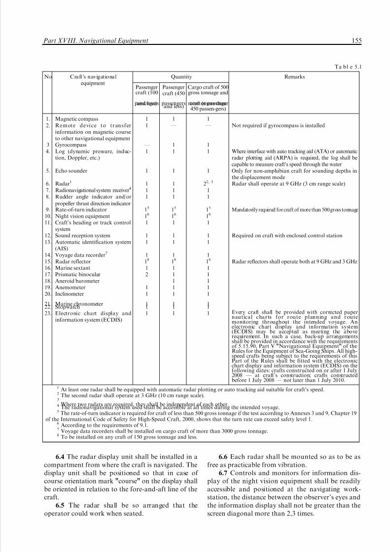
5/12/2018 High Speed Craft Rusa - slidepdf.com
http://slidepdf.com/reader/full/high-speed-craft-rusa 156/167
6.4 The radar display unit shall be installed in acompartment from where the craft is navigated. Thedisplay unit shall be positioned so that in case of course orientation mark "course" on the display shallbe oriented in relation to the fore-and-aft line of thecraft.
6.5 The radar shall be so arranged that theoperator could work when seated.
6.6 Each radar shall be mounted so as to be asfree as practicable from vibration.
6.7 Controls and monitors for information dis-play of the night vision equipment shall be readilyaccessible and positioned at the navigating work-station, the distance between the observer's eyes andthe information display shall not be greater than thescreen diagonal more than 2,3 times.
No Craft's navigationalequipment
Quantity
Passengercraft (100
passengersand less)
Passengercraft (450
passengersand less)
Cargo craft of 500gross tonnage and
more or passengercraft (more than450 passen-gers)
Remarks
1.2.
34.
5.
6.7.8.
9.10.11.
12.13.
14.15.16.17.18.19.20.
21.22.23.
Magnetic compassRe mote d e vi c e to tr an s ferinformation on magnetic courseto other navigational equipmentGyrocompassLog (dynamic pressure, induc-tion, Doppler, etc.)
Echo sounder
Radar1
Radionavigational system receiver4
Rudder angle indicator and/or
propeller thrust direction indicatorRate-of-turn indicatorNight vision equipmentCraft's heading or track controlsystemSound reception systemAutomatic identification system(AIS)Voyage data recorder7
Radar reflectorMarine sextantPrismatic binocularAneroid barometerAnemometerInclinometer
Marine chronometerStopwatchElectronic chart display andinformation system (ECDIS)
11
_
1
1
111
15
16
1
11
118
12
11
111
1 _
11
1
111
15
16
1
11
118
11111
111
1 _
11
1
22, 3
11
15
16
1
11
118
11111
111
Not required if gyrocompass is installed
Where interface with auto tracking aid (ATA) or automaticradar plotting aid (ARPA) is required, the log shall becapable to measure craft's speed through the waterOnly for non-amphibian craft for sounding depths inthe displacement modeRadar shall operate at 9 GHz (3 cm range scale)
Mandatorily required for craft of more than 500 gross tonnage
Required on craft with enclosed control station
Radar reflectors shall operate both at 9 GHz and 3 GHz
Every craft shall be provided with corrected papernautical charts for route planning and routemonitoring throughout the intended voyage. Anelectronic chart display and information system(ECDIS) may be accepted as meeting the aboverequirement. In such a case, back-up arrangementsshall be provided in accordance with the requirementsof 5.15.90, Part V "Navigational Equipment" of theRules for the Equipment of Sea-Going Ships. All high-speed crafts being subject to the requirements of thisPart of the Rules shall be fitted with the electronicchart display and information system (ECDIS) on thefollowing dates: crafts constructed on or after 1 July2008 _ at craft's construction; crafts constructedbefore 1 July 2008 _ not later than 1 July 2010.
1 At least one radar shall be equipped with automatic radar plotting or auto tracking aid suitable for craft's speed.2 The second radar shall operate at 3 GHz (10 cm range scale).3
Where two radars are required, they shall be independent of each other.4 The radionavigational system used shall be accessible at all times during the intended voyage.5 The rate-of-turn indicator is required for craft of less than 500 gross tonnage if the test according to Annexes 3 and 9, Chapter 19
of the International Code of Safety for High-Speed Craft, 2000, shows that the turn rate can exceed safety level 1.6 According to the requirements of 9.1.7 Voyage data recorders shall be installed on cargo craft of more than 3000 gross tonnage.8 To be installed on any craft of 150 gross tonnage and less.
T a b l e 5 .1
Part XVIII. Navigational Equipment 155
5/12/2018 High Speed Craft Rusa - slidepdf.com
http://slidepdf.com/reader/full/high-speed-craft-rusa 157/167
6.8 The sensor of the night vision equipment shallbe arranged so that:
.1 in the required horizontal field of view thereare no shadow sectors forward of the bow on either
side to 308;.2 in the required vertical field of view, sea surface
shown on the screen shall not reduce by more thantwo lengths of the ship following changes of theshadow zone of the ship due to vertical inclinations of the sensor.
7 SOURCES OF POWER
7.1 Navigational equipment required by this Partshall be supplied from the main and emergency
sources of electrical power in compliance with therequirements of Part XI "Electrical Equipment" of the present Rules.
7.2 Each navigational instrument indicated inTable 5.1 and requiring electrical power shall besupplied from the navigational equipment switch-board by separate feeders. Power supply to switch-board busbars shall be provided from the mainswitchboard and from the emergency switchboard bytwo separate feeders.
7.3 Magnetic compasses shall be illuminatedfrom the main and emergency sources of electricalpower.
8 SPARE PARTS
8.1 Spare parts for all navigational instrumentsshall be provided in accordance with 2.5, Part V"Navigational Equipment" of Rules for the Equip-ment of Sea-Going Ships.
The number of spare parts may be changed onagreement with the Register depending on naviga-tional conditions and duration of the voyage.
9 NIGHT VISION EQUIPMENT
9.1 For navigation of high-speed craft in dark time,they shall be fitted with night vision equipment.
10 CRAFT CONTROL STATIONS
10.1 All control functions of the craft when underway in any mode shall be exercised from the craftcontrol station at the navigating bridge.
10.2 The craft control station shall be positionedin the upper part of the superstructure or be raisedabove the upper deck. The operating compartmentshall be fitted with windows around the periphery to
provide view all round the horizon when at sea and inmanoeuvring the craft to a berth. Where all-roundview is not provided, two control stations shall bearranged.
At least one exit to the craft's side or stern shallbe provided at the craft's operating compartment.Besides, the operating compartment shall commu-nicate with interior spaces. Arrangements shall bemade to prevent passengers from entering theoperating compartment.
10.3 Blind sectors shall be as few as possible. Thetotal arc of blind sectors from right ahead to 22,58
abaft the beam on either side shall not exceed 208.Each individual blind sector shall not exceed 58 andthe clear sector between two blind sectors shall not beless than 108. The view of the sea surface from thecontrol station, when the navigators are seated, shallnot be obscured by more than one craft lengthforward of the bow to 908 on either side, irrespectiveof the craft draught, trim and deck cargo.
10.4 The control station of the craft shall be, asfar as possible, such as to ensure visual observationfor the navigators and utilization of leading marksastern of the craft.
10.5 The number of workstations for personnel
on watch in the craft control station shall besufficient to normally maintain the watch and steerthe craft. The required vision of the surroundingsfrom each workstation sufficient for the operatingpersonnel to perform their duties shall be provided.
10.6 The number of workstations and theirarrangement depending on a possibility of all-roundview, procedure of maintaining the watch by anavigator, helmsman, craft engineer and radiooperator as well as on the extent of craft automationmay be different and are subject to special considera-tion by the Register.
10.7 Where a docking station is provided fordocking the craft, the field of vision from the dockingworkstation shall permit one navigator to safelymanoeuvre the craft to a berth.
10.8 If separate workstations for supervision of engine performance and use of the radio equipmentare placed in the operating compartment, thelocation and use of these workstations shall notinterfere with primary functions in the operatingcompartment.
10.9 Each workstation shall be equipped with aseat, control panels with all necessary controls for theofficer in charge to perform all the prescribed functions.
10.10 Seats shall be comfortable and so positionedthat in the operational mode each operating crew
156 Rules for the Classification and Construction of High-Speed Craft

5/12/2018 High Speed Craft Rusa - slidepdf.com
http://slidepdf.com/reader/full/high-speed-craft-rusa 158/167
member could be seated facing right ahead. The heightof the seat shall be adjustable so that, in addition to theview referred to in 10.3, all indicators, controls andalarms referred to 10.16 could be easily used.
10.11 Seats shall be provided with safety beltsand permanently attached in the most convenientposition for the personnel in charge which shall notbe changed during the craft operation. The operatingcrew members, with the seats suitably adjusted andsafety belts correctly worn, shall be able to performthe operations referred to in 10.10. Subsequentchange of seat position to operate any control shallnot be acceptable. Exception may be made only inrespect of controls which are required on very rareoccasions and which are not associated with the needfor safety restraint.
10.12 A table suitable for chart work and recordkeeping in a logbook at the workstation shall be of asize sufficient for keeping nautical charts andpublications thereon. The table shall be so placedthat the navigator could work with charts andpublications not leaving the seat.
10.13 The dimensions of the table at the work-station shall be not less than:
.1 760 mm in width;
.2 660 mm in depth.10.14 The arrangement of the equipment in the
control station is subject to special consideration bythe Register.
10.15 Where an automatic steering aid isprovided, a chart table may be positioned beyondthe workstation but close thereto. In such case theofficer in charge may temporarily leave the seat.
10.16 The following devices and instruments shallbe located at each workshop in the control station:
.1 levers to control main engines direction andspeed of rotation or engine telegraph hand levers;
.2 hand levers, buttons or wheels of directionalcontrol systems, i.e. steering engines, foils, flaps,steerable propellers, jets, yaw control ports, sidethrusters, differential propulsive thrust, variable
geometry of the craft or its lifting-system compo-nents, aerial or water rudders, lift fans, etc.;
.3 main engine rotational speed and directionindicators, course indicators, rudder angle indicators,position indicators of foils, flaps, sterable propellers,
jets, yaw control ports, side thrusters, differentialpropulsive thrust, variable geometry of the craft or itslifting-system components, aerial or water rudders,lift fans, etc.;
.4 alarms on failures in engines, control devices andsystems referred to in 10.16.1, 10.16.2 and 10.16.5;
.5 craft's automatic stabilization system controlstation and automatic safety control station;
.6 hand controls of safety device of automaticstabilization system of craft modes;
.7 illuminated indicator panels and sound alarmsof the warning and alarm systems of craft automatedmachinery, systems and arrangements;
.8 illuminated indicator panels and sound alarms
of fire detection systems;.9 a device for remote starting of fire-extinguish-
ing systems;.10 navigation light boards and associated
signalling systems;.11 navigational equipment required by this Part;.12 radio equipment required by Part XVII
"Radio Equipment";.13 light and sound signalling devices on failures
in ventilation system for special-category spaces;.14 switches for remote stopping of fans in
accommodation, service, machinery spaces and in
special-category spaces;.15 instruments for measuring temperature,pressure, level of liquid, voltage, load and otheressential parameters of craft propulsion machineryand arrangements;
.16 remote arrangements for stopping flammableliquid transfer pumps and fire-extinguishing systemscontrol;
.17 alarms on high water level in drained spaces;
.18 any other instruments, arrangements, con-trols, including those for emergency purposes, whichmay be required depending on the craft structure.
10.17 The equipment referred to in 10.16 shall be
arranged on consoles, bulkheads, desks, etc. It shallhave such design and size of light and digitalindicator scales, signal lamps, controls, and be somounted and illuminated that operating personnelcan easily view the instruments and operate thecontrols without leaving their seats in all possibleservice conditions.
10.18 All alarm, indication and monitoringinstruments referred to in 10.16, and controls shallbe logically grouped according to their function. Thealarm, indication and monitoring instruments shallbe clearly marked with any limitation if this
information is not otherwise clearly presented to theoperating crew. The instrument panels forming theemergency control for the monitoring of the fire-fighting systems and launching of liferafts, etc. shallbe grouped and be separate. The instruments shallnot be rationalized by sharing functions or by inter-switching.
10.19 The alarm, indication and monitoringinstruments shall be so designed as to be plainlyvisible at any level of lighting. Glare and reflectionsfrom the instruments shall not interfere with normalwork of the operating personnel at nighttime.
10.20 The surfaces of the alarm, indication andmonitoring instruments, and console tops shall havedark, matt, glare-free colours.
Part XVIII. Navigational Equipment 157

5/12/2018 High Speed Craft Rusa - slidepdf.com
http://slidepdf.com/reader/full/high-speed-craft-rusa 159/167
10.21 Only the most essential equipment shall bearranged in front of the operating crew membersfacing right ahead, provided their attention andobservation of the surroundings is not prevented.
Where indications of the alarm, indication andmonitoring instruments and visual information onthe displays of navigational equipment shall be usedby more than one person, they shall be located foreasy viewing by all users concurrently. If this is notpossible, the instrument or display shall be dupli-cated.
10.22 Where maintaining watch and radioequipment control at workstations are difficult dueto arrangement of the radio equipment used, a specialworkstation for the radio operator, in addition to theworkstations referred to in 10.5, shall be provided.
The VHF radio installation control desk shall bepositioned in all cases at the workstations referred toin 10.5.
10.23 Means to communicate between theoperating compartment and spaces containing essen-tial machinery, such as propulsion machinery,emergency steering positions, etc., shall be provided.
10.24 A portable microphone shall be provided inthe operating compartment for making publicaddress and safety announcements to all areas towhich passengers and crew have access and throughwhich escape paths are routed, and to all survivalcraft embarkation stations.
10.25 The operating compartment shall beequipped with adequate temperature and ventilationcontrol systems.
10.26 An adequate level of lighting shall beprovided in the operating compartment to enable theoperating personnel to efficiently perform their tasksboth at sea and in port. Red light shall be used tomaintain dark adaptation whenever any items of equipment other than the chart table require localillumination in the operational mode.
10.27 Lighting in the operating compartment andnoise generated by the instruments installed in the
operating compartment shall not produce any inter-ference for navigation.
10.28 Where provision is additionally made tocontrol the craft from control stations other than thecraft's operating compartment referred to in 10.2, thealarm, indication and monitoring instruments andcontrols shall be switched over to operation fromother stations only from the craft's operatingcompartment.
10.29 Sockets supplied from the emergencysource of electrical power for connection of aportable lamp which shall be permanently kept inthe craft control station shall be provided in the craft.
10.30 Where the craft control station is equippedwith a combined craft control panel, one shall be
guided by the provisions of this Section, those of 5.12, Part V "Navigational Equipment" of Rules forthe Equipment of Sea-Going Ships and 4.5 "Elec-trical Equipment" of the Rules for the Classification
and Construction of Sea-Going Ships.10.31 Divisions between windows shall be kept to
a minimum. No division shall be installed immedi-ately forward of the officer in charge and helmsmanworkstations.
10.32 The arrangement of the control stationwindows and the curvature of their surface shall besuch that no glare, reflections or distortions areproduced which might result in navigation errors.Neither polarized or tinted window glass shall befitted. The windows shall be angled from the verticalplane top out to not less than 108 but not more than
258 to reduce unwanted reflections. Windows shall bemade of a material which will not break intodangerous fragments if fractured.
10.33 Front windows and, depending of config-uration of the control station, other window shall beprovided with means for wiping, heating and airblowing of the windows. The means shall be soarranged that no reasonably probable single failurecan result in a reduction of the cleared field of visionfrom the operating compartment.
10.34 The design and software of the equipmentarranged in the operating compartment shall be suchas to prevent their use for purposes other than
navigation, communication and other functionsessential to the safe operation of the craft.
11 OPERATIONAL REQUIREMENTS
FOR NAVIGATIONAL EQUIPMENT
11.1 General requirements.
11.1.1 All navigational instruments and devicesthat are part of the craft's navigational equipmentshall have technical characteristics not lower thanthose required by this Part of the Rules, and they
shall be arranged so that safety of navigation isensured in the area and under conditions for whichthe craft is intended.
11.1.2 All navigational equipment required bythis Part of the Rules as well as the navigational aidsto be installed on high-speed craft in addition tothose required shall comply in respect of theirtechnical characteristics with the requirements of Section 5, Part V "Navigational Equipment" of theRules for the Equipment of Sea-Going Ships,provided they are not specially defined in this Part,and with special requirements dictated by high speedsof the craft between 30 and 70 knots. Suchrequirements, if they are not set forth below, aresubject to special consideration by the Register.
158 Rules for the Classification and Construction of High-Speed Craft

5/12/2018 High Speed Craft Rusa - slidepdf.com
http://slidepdf.com/reader/full/high-speed-craft-rusa 160/167
11.2 Radars.
11.2.1 The radars installed on HSCs on or after1 July 2008 shall comply with the requirements of Section 5.7, Part V "Navigational Equipment" of the
Rules for the Equipment of Sea-Going Ships. Thenumber of the radars required shall comply with therequirements of Table 5.1 of this Part of the Rules andtheir performance characteristics, depending on grosstonnage, shall comply with the requirements of Table5.7.2, Part V "Navigational Equipment" of the Rulesfor the Equipment of Sea-Going Ships. In this case, aspeed of aerial rotation shall be at least 40 rpm. Theradars installed on HSCs before 1 July 2008 shallcomply with the performance standards given below.
11.2.2 The radar shall be capable of providing aclear indication of coastlines, surface objects and
locating their position giving continuous uninter-rupted all round scanning of the horizon under trueand relative motion presentation. All radars operat-ing in 3 cm range shall have horizontally polarizedradiation.
11.2.3 Where the radar antenna is mounted at aheight of 7,5 m above sea level, the radar display unitshall be capable of giving clear indication of surfaceobjects, such as navigation buoys having an effectiveechoing area of 10 m2 at 2,5 nautical miles in theabsence of clutter. These objects shall be clearly seenat the radar display at a minimum distance of 35 mand up to a distance of one nautical mile without
changing of controls position except the range scaleswitch. The above-mentioned requirements shall bemet at rolling and pitching motions up to 108.
11.2.4 The radar display shall have an effectivediameter of at least 250 mm without any outsidemagnifying instruments. The display shall providemulti-colour presentation and adjustment of itsbrightness. Provision shall be made for the quickchange of colour presentation for better observationboth in daytime and at night.
The display unit of the radar shall be providedwith the following set of range scales: 0,25; 0,5; 0,75;
1,5; 3; 6; 12 and 24 nautical miles. Additional rangescales may be provided. There shall be indicated notless than two fixed electronic range rings on the rangescales 0,25, 0,5 and 0,75 nautical miles, and up to sixrings on the other scales.
The nominal value of the range scale and distancebetween fixed electronic range rings shall be clearlyindicated on the working part of the display unit.
Besides, variable electronic range ring with anumeric read-out of the range shall be provided.
The fixed and the variable range rings shallensure the accuracy of measurement of the objectrange with an error not exceeding 1 per cent of themaximum range of the scale in use, or 30 m,whichever is the greater.
Provision shall be made for off-set of the centreof scanning at least for 50 per cent but not more thanfor 75 per cent from the range scale used.
It shall be possible that brightness of the fixed
and a variable range rings be varied up to their totalremoval from the display.
11.2.5 The display unit of the radar shall have anelectronic direction sighting device intended fordetermination of the direction to any target whichmark appears on the screen. The error of measure-ment of the direction to a target which is on the edgeof the screen shall not exceed +18.
Provision shall be made for at least two lines of the direction sighting device.
After installation on the craft and adjustment theaccuracy of measurement of the direction to the
target shall be maintained without any adjustmentsindependently of the craft movement in magneticfields of the Earth.
11.2.6 The craft heading shall be indicated on thescreen by means of electronic course mark in theform of a line with a maximum error +18. The widthof the course mark at the edge of the display faceshall not exceed 0,58.
The possibility shall be provided for temporaryremoval of the course mark image using a switch withautomatic reset to "on" position.
11.2.7 Provision shall be made for indication onthe screen of the display unit, along with radar
information, of the planned route in graphical form,i. e. route points and segments of straight linesconnecting them. The source of graphical informa-tion shall be clearly indicated.
The possibility shall be provided for displayingtarget motion trajectories in the form of trails createdby marks of targets due to the screen artificialafterglow.
Trails shall be relative or true, true trails shall bestabilized relative to the water or ground.
11.2.8 The radar shall have a resolution that, inthe absence of clutter, provides:
.1 on 1 mile range scale and less, separateindication of two objects with an effective targetarea of 10 m2 located on the same azimuth at thedistance equal to 50 _ 100 per cent of the rangenominal value of the range scale used and distant notmore than 35 m from each other;
.2 on 1,5 mile range scale and less, separateindication of two objects with an effective target areaof 10 m2 located at the same distance within 0,5 to1 mile limits and not more than 2,58 from each otherfor radar operating in 3 cm range and not more than48 for radar operating in 10 cm range.
11.2.9 Devices shall be provided to eliminateclutter created by reflections from precipitation,clouds, sand storms and sea surface.
Part XVIII. Navigational Equipment 159

5/12/2018 High Speed Craft Rusa - slidepdf.com
http://slidepdf.com/reader/full/high-speed-craft-rusa 161/167
Provision shall be made for smooth manualregulation of such devices and for switching off thosesignal processing devices which may prevent reflec-tion from the radar beacon responder.
11.2.10 The radar shall be ready for operationwithin 4 min upon being switched on. The "stand-by"position shall be provided after which the radar maybe set in the "switched on" position within 15 s.
11.2.11 Means shall be provided to check anddetermine a substantial drop in performance relativeto the manufacturer calibration standard and tocheck that the equipment is correctly adjusted in theabsence of targets indication on the screen of thedisplay unit.
11.2.12 The radar shall be capable of receivinginformation signals from gyrocompass, log, receivers
of radionavigation systems. Alarms on absence ordecreasing of quality of information signals from theabove-mentioned equipment shall be duplicated.
11.2.13 The radar shall be capable to provide all-round view over the entire horizon in the relativemotion mode. The accuracy of alignment with acourse information source shall be within +0,58 witha rotation rate of 208/s.
The radar shall operate properly in the absence of a signal from a course information source.
It is recommended to provide the possibility of radar operation in the true motion mode.
11.2.14 Provision shall be made in the radar for
clockwise continuous and automatic scan through3608 of azimuth. The scan rate shall be not less than40 rpm.
The antenna shall be capable to operate with arelative wind velocity up to 100 knots.
11.2.15 Controls shall be readily accessible andeasily recognizable.
In case symbols are used for their indication, theyshall correspond to commonly used symbols foridentification of navigation marine radar controls.The navigator shall be able to switch on and operatethe radar from his workstation, when seated.
11.3 Gyrocompasses.11.3.1 In craft whose speed is below 30 knots the
gyrocompass shall comply with the requirements of 5.3, Part V ªNavigational Equipmentº of the Rulesfor the Equipment of Sea-Going Ships; for crafthaving speeds between 30 and 70 knots the gyro-compass shall meet the requirements given below.
11.3.2 The gyrocompass positioned on a hor-izontal and stationary base on board the craftoperating in latitudes of up to 708 shall comply withthe following requirements:
.1 the gyrocompass shall be brought into align-ment with meridian within 6 hours;
.2 the steady-state error at any course shall notexceed +0,758 x secant latitude, the root mean
square value of the difference between individualcourse indications and the mean value of the courseshall be not less than +0,258 x secant latitude;
.3 the permissible error from one run-up to
another shall be within +0,258 x secant latitude.11.3.3 In latitudes between 708N and 708S, when
the craft operates within the latitude range 108, thegyrocompass shall comply with the following require-ments:
.1 under rolling and pitching harmonic motionswith a period of 6 to 15 s, amplitude of 58 at maxi-mum accelerations of 22 m/s2 the gyrocompass shallbe brought into alignment with meridian within 6 h;
.2 the steady-state error of the master compassreadings, from one run-up to another, under serviceconditions associated with variations of the magnetic
field and environmental temperature shall be within+18 x secant latitude;.3 the residual error at a straight course (after
correction for speed and course at a speed of 70 knotsshall not exceed +0,258 x secant latitude;
.4 the maximum error of readings due to a rapidacceleration of the craft up to a speed of 70 knotsshall not exceed 2;
.5 the error of readings due to rapid alteration of course of 1808 at a turn angular speed 208/s and speedof 70 knots shall not exceed +38;
.6 steady and variable errors of the indicationscaused by harmonic rolling up to 208, pitching up to
108 and yawing up to 58 with a period from 6 to 15 sand the maximum horizontal acceleration not morethan 1 m/s2 at any course (in particular, 458, 908 and3158) shall not exceed +18 x secant latitude;
.7 gyrocompasses shall operate reliably as it isrequired in 5.1.2, Part V "Navigational Equipment"of the Rules for the Equipment of Sea-Going Ships;the maximum error shall not exceed +18;
.8 the maximum divergence in readings betweenthe master compass and repeaters shall not exceed+0,58 under any operational conditions;
.9 the respond rate of the gyrocompass follow-up
system shall be not less than 208/s.11.3.4 Gyrocompass shall be provided with a
compass card or analogue repeater for indication of course information, visual bearing taking devices aswell as a corrector used for correction of compassreadings in respect of craft speed and latitude.
The device shall be calibrated in 18 or 1/108increments. Digital markings shall be indicated inevery 108 clockwise from 0 to 3608.
In addition, a digital indicator may be provided.The course shall be presented on the digital indicatorin the form of three figures (the fourth figure mayindicate tenths of a degree). If a gyrocompass with adigital indicator is used it shall include a turnindicator.
160 Rules for the Classification and Construction of High-Speed Craft

5/12/2018 High Speed Craft Rusa - slidepdf.com
http://slidepdf.com/reader/full/high-speed-craft-rusa 162/167
11.3.5 The remote indication system of thegyrocompass shall be designed so as to ensuresimultaneous operation of gyrocompass own repea-ters, course recorder, as well as repeaters fitted in
other navigational equipment.11.3.6 A course recorder shall be capable of
recording craft course in respect of time with anaccuracy +1 %.
11.3.7 Provision shall be made for a visual and/oraudible indication of gyrocompass readiness foroperation as well as audible and visual alarms onpower supply failure or failures in the compass system.
11.3.8 The compass shall be supplied with electricpower from the main and emergency sources of power with automatic switching-over.
11.3.9 Gyrocompass shall be provided with
devices for correction of error due to a rapidalteration of craft's speed and influence of themagnetic field in different latitudes.
11.3.10 Appropriate interfaces shall be providedto transfer of the course information to othernavigation equipment, such as radars, ARPA,ATA, ETA, AIS, ECDIS, voyage data recorder,craft's heading control system or track controlsystem.
11.4 Craft heading control systems (automatic
steering devices).
11.4.1 The heading control system for HSC shallmeet the requirements of 5.16, Part V "Navigational
Equipment" of the Rules for the Convention Equip-ment of Sea-Going Ships as well as the requirementsgiven below and governed by specific features of HSCand the following operational conditions:
.1 craft speed 730 to 70 knots;
.2 maximum rate of turn 7208/s;
.3 navigation of the craft in latitudes up to 708.11.4.2 The heading control system shall enable
the craft to keep automatically the preset headingwith minimum operation of the craft steering gear.
11.4.3 The heading control system, having regardto the craft's manoeuvring qualities, shall enable the
craft to keep automatically the preset heading with anaccuracy of +28.
The heading control system shall be fitted with aregulator of permissible deviation from the presetheading (yaw), and the maximum amplitude of yawshall not exceed the amplitude permitted undermanual control. Means shall be incorporated in theheading control system to enable the rudder anglelimitation and an alarm to indicate when the angle of limitation has been reached.
11.4.4 The heading control system shall be able toperform turns within the craft turning capabilitiesand in accordance with 11.4.1.2.
11.4.5 The heading control system shall becapable of adapting automatically or manually to
different steering characteristics of the craft undervarious speeds, accelerations, loading conditions of the craft, sea and weather conditions. Means shall beprovided to control and correct the system para-
meters.11.4.6 Change-over from manual to automatic
steering and vice versa shall be possible at anyposition of the rudder. The heading control systemshall change to a preset heading without significantovershoot. Adequate indication shall be provided toshow which method of steering is in operation. Whenchanging from manual to automatic steering theheading control system shall take over the actualheading as the preset heading. Any possibility of inadvertent or unauthorized alteration of the presetcourse shall be prevented. Switching-over from
automatic to manual control shall be possible underany circumstances, even in case of the automaticcontrol system failure. In case of manual steering, apossibility shall be provided for preventing theautomatic steering operation.
11.4.7 Controls intended for changing frommanual to automatic steering method and vice versashall be located in the master station and close toeach other.
11.4.8 Controls intended for alteration of theheading shall be designed so as to ensure altering thepreset heading to starboard by turning the headingsetting control clockwise or tilting the control handle to
the right-hand side or a command for turning starboardif a control is a digital device. Alteration of the presetheading to port side shall be ensured by turning theheading setting control counter-clockwise or tilting thecontrol handle to the left-hand side or a command forturning to the port side if a control is a digital device.
The alteration of the preset heading shall bepossible by adjustment of only one the preset headingcontrol.
Controls at the remote control stations shall meetthe requirements of this Chapter. Change of thesystem control to a remote control station shall be
possible only from the master station.11.4.9 The heading control system shall be
electrically connected with a gyrocompass and receiveinformation on the heading.
11.4.10 An alarm shall be provided in the headingcontrol system to indicate failure of any headingmonitor used for control. All warning alarms likelyto appear when information transmitters are inoperation shall be duplicated at the craft's coursecontrol station.
11.4.11 The heading control system shall beprovided with audible and visual alarms to indicatefailure or reduction of power supply.
11.4.12 An alarm shall be provided when theactual heading deviates from the preset heading
Part XVIII. Navigational Equipment 161

5/12/2018 High Speed Craft Rusa - slidepdf.com
http://slidepdf.com/reader/full/high-speed-craft-rusa 163/167
beyond a preset limit, the heading track aid shall getinformation from an independent indicator.
11.4.13 Alarms shall be positioned at the steeringcontrol station.
11.4.14 Provision shall be made for connection of the heading control system with information sensorsas required by 5.1.31, Part V "Navigational Equip-ment" of Rules for the Equipment of Sea-GoingShips.
11.5 Night vision equipment.
11.5.1 Night vision equipment shall be designedfor continuous operation during night time (fromsunset to dawn). Night vision equipment shall bedesigned so that it detects objects above water surfaceat a given distance from the ship which threatenshipping, such as small unlit boats, floating logs, oil
drums, containers, buoys, ice, whales, etc. and showsthem on the screen.Night vision equipment shall determine position
of such objects in relation to the ship and displaythem in real time.
11.5.2 After the equipment has been switched onit shall be operational in less than 15 min.
11.5.3 Night vision equipment shall detect thestandard test target at a distance of at least 600 mwith a minimum probability of 90 per cent undermean starlight conditions without clouds and withoutmoon. The standard target shall be a black metalobject of such a size that when at least 50 per cent is
immersed, 1,5 m long and 0,5 m high remains abovewater at right angles to the desired direction of detection. The standard test target shall stay at least24 h in water before testing.
11.5.4 Equipment shall enable detection anddisplay of objects staying in:
horizontal field of view shall be at least 208, 108on either side of the bow;
vertical field of view shall be at least 128,meanwhile observation of the horizon shall beprovided.
Other sectors of view may be provided. They shall
be activated by special non-locking switch whichreturns to the required field of view when released.
Watch navigator working place shall be equippedwith the visual indication of the sector of view in use.
11.5.5 The axis of the field of view of theequipment shall be capable of being moved at least208 horizontally to either side. The system shall becapable of panning at a minimum angular speed of 308/s. This shift shall be made by a single control andthe equipment shall be capable to revert automati-cally to the initial sector of view to the ahead positionat a minimum angular speed of 308/s.
11.5.6 The elevation axis of the field of view shallbe capable of being adjusted by at least 108 tocompensate for the trim of the craft.
11.5.7 The heading marker of the craft shall beindicated on the display with an error not greaterthan +18.
A visual indication of relative bearing with an
error of not greater than +18 shall be provided, itshall appear while the axis of horizontal field of viewhas shifted to the corner when the heading markerdisappears from the display.
11.5.8 Sensor of the night vision equipment shallbe designed so that it operates at the followingweather conditions:
pitching and/or rolling up to 108;relative velocity of the head wind and / or true
wind up to 100 knots;icing;spattering or thumbing of the sensor lens.
It shall be possible to clean sensor lens from theship control station.If the sensor rotating mechanism fails, it shall be
possible to fix it in the forward direction.11.5.9 The equipment shall be designed so that to
exclude or reduce to minimum such hindrances likedazzle or reflection of light, glow or other visualinterferences.
11.5.10 Equipment shall have indication that it isup and running.
11.5.11 Night vision equipment shall include avisual indication of any failure.
11.5.12 Number of controls shall be minimal.
Clear notes and/or conventional symbols shallindicate their purpose.
It is not recommended to use controls of dualpurpose as well as to apply Menus for operation of equipment.
11.5.13 Controls shall be clearly visible indarkness. If they are fitted with lighting it shall beadjustable.
11.5.14 Information display of night visionequipment shall not twinkle or blind craft operatingcrew. Screen diagonal shall be sufficient to showimage of at least 180 mm by diagonal.
11.5.15 If any function of the night visionequipment is realized by means of software, it shall:
display the user interface status;contain self-description of the functions imple-
mented by means of software;be protected from casual and/or unauthorised
changes;meet requirements of Part XV "Automation" of
Rules for the Classification and Construction of Sea-going Ships.
11.5.16 If manufacturer recommends to carry outmaintenance works of the equipment regularly, itshall be fitted with the elapsed operation timecounter.
162 Rules for the Classification and Construction of High-Speed Craft

5/12/2018 High Speed Craft Rusa - slidepdf.com
http://slidepdf.com/reader/full/high-speed-craft-rusa 164/167
1 GENERAL
1.1 Unless expressly provided otherwise, signalmeans of HSC shall meet the requirements of Part III"Signal Means" of Rules for the Equipment of Sea-Going Ships.
2 EQUIPMENT OF CRAFT WITH SIGNAL MEANS
2.1 In addition to those lanterns which are
indicated in 2.2.4 of Part III "Signal Means" of Rules for the Equipment of Sea-Going Ships a set of spare lanterns for air-cushion vehicles shall include ayellow flashing light.
2.2 At least 12 red rocket parachute flares shall bestowed in the craft control station.
2.3 One portable signalling lamp capable of operating independently of the craft main electricalsupply shall be provided and maintained ready foruse in the control station at all times.
2.4 HSC shall be equipped with at least oneadequate searchlight, which shall be controllablefrom the control station.
3 FITTING OF SIGNAL MEANS ON BOARD
3.1 Fixed installation of a craft bell is notrequired but a device shall be provided for quickinstallation thereof in its regular place.
The bell and the device shall be stowed in closevicinity of the installation place.
3.2 The forward masthead light or if there is onlyone masthead light on HSC with a length to breadthration less than three may be positioned at a heightless than required in 4.2.1.1, Part III "Signal Means"of Rules for the Equipment of Sea-Going Ships,
provided the angles at the base of the isoscelestriangle viewed from the craft ends and formed byside lanterns and topmast lantern are not lessthan 278.
3.3 The yellow flashing light in air-cushionvehicles shall be installed so that there is no flashinglight reflection from craft structures or is kept to aminimum, which impair observation of the surround-ings.
Part XIX. Signal Means 163
PART XIX. SIGNAL MEANS

5/12/2018 High Speed Craft Rusa - slidepdf.com
http://slidepdf.com/reader/full/high-speed-craft-rusa 165/167
>AA89A:89 <>@A:>9 @538AB@ AC4>E>4AB20
@028;0 :;0AA8D8:0F88 8 ?>AB@>9:8 2KA>:>A:>@>AB=KE AC4>2
2008 3.
Russian Maritime Register of Shipping
Rules for the Classification and Construction of High-Speed Craft
2008
The edition is prepared by Russian Maritime Register of Shipping
8, Dvortsovaya Naberezhnaya, 191186, St. Petersburg, Russian Federation
Tel.: +7(812) 312-89-59Fax: +7(812) 312-89-86

5/12/2018 High Speed Craft Rusa - slidepdf.com
http://slidepdf.com/reader/full/high-speed-craft-rusa 166/167

5/12/2018 High Speed Craft Rusa - slidepdf.com
http://slidepdf.com/reader/full/high-speed-craft-rusa 167/167