Embed Size (px)
Citation preview
HIGH-RISE DESIGN AND THE USE OF HIGH STRENGTH STEEL
M. O’Connor
WSP Cantor Seinuk, 70 Chancery Lane, London, WC2A 1AF, UK
Keywords: Tall Buildings, Structural Design, Structural Systems, High Strength Steels, Niobium
Abstract
High-rise design involves a delicate balancing act of meeting the aspirations of the client,
architect, regulatory authorities and the myriad of other design professionals working on the
scheme. This balancing act often means that the main structural elements providing stability to
the building need to be sized to minimise their impact on the building. It is in these situations
that the structural engineer starts to consider the use of high strength steel (355 N/mm2 and
greater) to help achieve his/her goals.
This paper explores the main drivers in the design of high-rise buildings, the common lateral and
vertical load carrying systems adopted and the important role high strength steels can play to
make the buildings feasible. The paper will use a number of case studies from WSP’s extensive
portfolio of tall building projects in the United States, United Kingdom and Asia. In each case,
the key design considerations will be explored and the important benefits realised by the use of
high strength steel, microalloyed with elements such as niobium, explained.
Introduction
The financial and economic challenges of development on inner city sites are continuing to push
building designs taller and taller. This gives the structural engineer numerous challenges in
deriving designs which meet the competing functional requirements of tall buildings in a cost
effective manner. High-rise design involves a delicate balancing act of meeting the aspirations of
the client, architect, regulatory authorities and the myriad of other design professionals working
on the scheme. This balancing act often means that the main structural elements providing
stability need to be sized to minimise their impact on the building. It is in these situations that the
structural engineer starts to consider the use of high strength steel to help achieve his/her goals.
WSP Cantor Seinuk is part of WSP Genivar, one of the world’s largest global consultancies.
From its structural engineering offices in New York, London, the Middle East and Asia, it has
been responsible for the design of some of the world’s tallest buildings, including the Freedom
Tower in New York, The Shard in London and the Nakheel Tower in Dubai. Each building
brings its own structural challenges and high strength steel has a role to play in meeting those
challenges. To fully understand that role, the key demands of the different parts of the structural
stability system need to be understood.
This paper explores the main drivers in the structural design of high-rise buildings, the common
lateral and vertical load carrying systems adopted and the important role high strength steels can
play to make the buildings feasible.
1
Proceedings of the Value-Added Niobium Microalloyed Construction Steels SymposiumCBMM and TMS, 2015
High-rise Design
Design Process
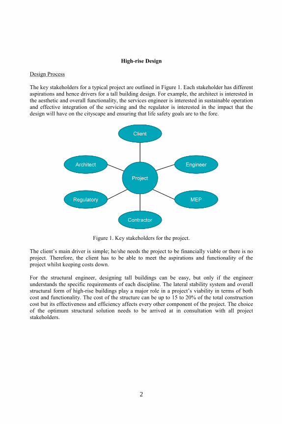
The key stakeholders for a typical project are outlined in Figure 1. Each stakeholder has different
aspirations and hence drivers for a tall building design. For example, the architect is interested in
the aesthetic and overall functionality, the services engineer is interested in sustainable operation
and effective integration of the servicing and the regulator is interested in the impact that the
design will have on the cityscape and ensuring that life safety goals are to the fore.
Figure 1. Key stakeholders for the project.
The client’s main driver is simple; he/she needs the project to be financially viable or there is no
project. Therefore, the client has to be able to meet the aspirations and functionality of the
project whilst keeping costs down.
For the structural engineer, designing tall buildings can be easy, but only if the engineer
understands the specific requirements of each discipline. The lateral stability system and overall
structural form of high-rise buildings play a major role in a project’s viability in terms of both
cost and functionality. The cost of the structure can be up to 15 to 20% of the total construction
cost but its effectiveness and efficiency affects every other component of the project. The choice
of the optimum structural solution needs to be arrived at in consultation with all project
stakeholders.
2
The main structural engineering challenges in helping meet the client’s aspirations are therefore:
Design an overall framing system that requires the least amount of construction material (an
essential part of any credible sustainable development strategy);
Maximise the number of floors per given height;
Provide the maximum net-to-gross area on each floor in the building.
Structural Form
Tall buildings are basically cantilevers out of the ground. As the number of floors increase, the
gravitational forces increase, requiring stronger material for columns, shear walls and
foundations. In addition, lateral loads such as wind and seismic forces increase rapidly with
height. If we consider that tall buildings are cantilevers, then as height increases then so does the
lever arm of the lateral loads and hence the overturning moment at the base of the building.
Therefore, above a certain height the lateral stability system becomes the dominant structural
concern.
In terms of overall structural performance, there are a number of performance criteria that need
to be met. The first is obviously strength; the overall strength of the system has to be sufficient to
sustain the loads applied to it. However, in high-rise design serviceability aspects often govern.
The structure has to be stiff enough that the façade providing the protective envelope of the
building maintains water tightness whilst undergoing the deflections imposed on the building by
lateral forces. The structure also has to be stiff enough to ensure that the dynamic characteristics
are such that occupants do not become uncomfortable by the inevitable motion set up when the
building is buffeted by fluctuating wind loads at high level. In addition to these main
performance characteristics, buildings have to be robust under seismic and accidental events and
also have to be durable, ie are designed for a certain design life.
A number of structural forms for lateral stability are available and the suitability of each form
will vary dependent on height, site constraints, geotechnical conditions, the needs of other
stakeholders, etc. At present, the most common high-rise structural forms available include:
Interior core;
Interior core with outriggers;
Perimeter tube;
Diagrids.
Some of the forms are only suitable and financially viable below a certain height. For example,
interior core forms are usually designed by placing concrete shear walls or steel braced frames
around the main lift cores and service risers forming a vertical spine to the building. As vertical
transportation technology and effectiveness of service provision improve, the proportion of floor
area required for services reduces with height. If we consider that the effectiveness of resisting
an overturning moment is dependent on the width of the base of the lateral stability system, then
it can be seen that the core walls alone become inefficient in sustaining a building above a
certain height. An example of a pure core supported form would be The Shard at London Bridge,
Figure 2.
3
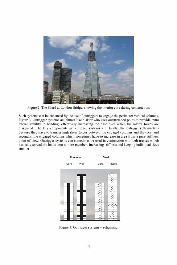
Figure 2. The Shard at London Bridge, showing the interior core during construction.
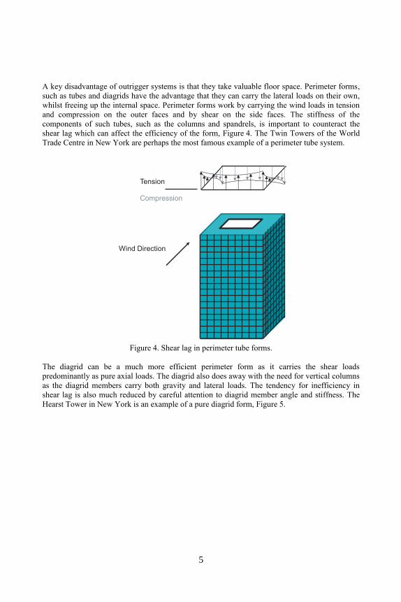
Such systems can be enhanced by the use of outriggers to engage the perimeter vertical columns,
Figure 3. Outrigger systems act almost like a skier who uses outstretched poles to provide extra
lateral stability in bending, effectively increasing the base over which the lateral forces are
dissipated. The key components in outrigger systems are, firstly, the outriggers themselves
because they have to transfer high shear forces between the engaged columns and the core, and
secondly, the engaged columns which sometimes have to increase in area from a pure stiffness
point of view. Outrigger systems can sometimes be used in conjunction with belt trusses which
basically spread the loads across more members increasing stiffness and keeping individual sizes
smaller.
Section
Plan
Type I
Wall
SteelConcrete
With
ou
trig
ge
rs
TrussesCoreCore
Figure 3. Outrigger systems – schematic.
4
A key disadvantage of outrigger systems is that they take valuable floor space. Perimeter forms,
such as tubes and diagrids have the advantage that they can carry the lateral loads on their own,
whilst freeing up the internal space. Perimeter forms work by carrying the wind loads in tension
and compression on the outer faces and by shear on the side faces. The stiffness of the
components of such tubes, such as the columns and spandrels, is important to counteract the
shear lag which can affect the efficiency of the form, Figure 4. The Twin Towers of the World
Trade Centre in New York are perhaps the most famous example of a perimeter tube system.
Wind Direction
Tension
Compression
Figure 4. Shear lag in perimeter tube forms.
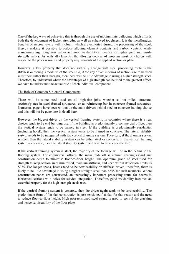
The diagrid can be a much more efficient perimeter form as it carries the shear loads
predominantly as pure axial loads. The diagrid also does away with the need for vertical columns
as the diagrid members carry both gravity and lateral loads. The tendency for inefficiency in
shear lag is also much reduced by careful attention to diagrid member angle and stiffness. The
Hearst Tower in New York is an example of a pure diagrid form, Figure 5.
5
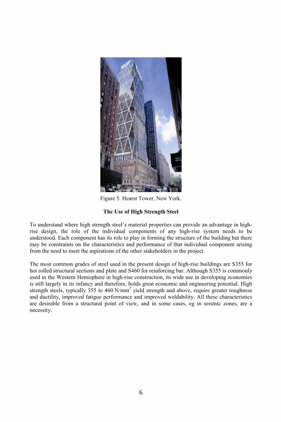
Figure 5. Hearst Tower, New York.
The Use of High Strength Steel
To understand where high strength steel’s material properties can provide an advantage in high-
rise design, the role of the individual components of any high-rise system needs to be
understood. Each component has its role to play in forming the structure of the building but there
may be constraints on the characteristics and performance of that individual component arising
from the need to meet the aspirations of the other stakeholders in the project.
The most common grades of steel used in the present design of high-rise buildings are S355 for
hot rolled structural sections and plate and S460 for reinforcing bar. Although S355 is commonly
used in the Western Hemisphere in high-rise construction, its wide use in developing economies
is still largely in its infancy and therefore, holds great economic and engineering potential. High
strength steels, typically 355 to 460 N/mm2 yield strength and above, require greater toughness
and ductility, improved fatigue performance and improved weldability. All these characteristics
are desirable from a structural point of view, and in some cases, eg in seismic zones, are a
necessity.
6
One of the key ways of achieving this is through the use of niobium microalloying which affords
both the development of higher strengths, as well as enhanced toughness. It is the metallurgical
benefits of microalloying with niobium which are exploited during the processing of the steel,
thereby making it possible to reduce alloying element contents and carbon content, while
maintaining high toughness values and good weldability at identical or higher yield and tensile
strength values. As with all elements, the alloying content of niobium must be chosen with
respect to the process route and property requirements of the applied section or plate.
However, a key property that does not radically change with steel processing route is the
stiffness or Young’s modulus of the steel. So, if the key driver in terms of section size to be used
is stiffness rather than strength, then there will be little advantage to using a higher strength steel.
Therefore, to understand where the advantages of high strength can be used to the greatest effect,
we have to understand the actual role of each individual component.
The Role of Common Structural Components
There will be some steel used on all high-rise jobs, whether as hot rolled structural
sections/plates in steel framed structures, or as reinforcing bar in concrete framed structures.
Numerous papers have been written on the main drivers behind steel or concrete framing choice
and this will not be gone into in detail here.
However, the biggest driver on the vertical framing system, in countries where there is a real
choice, tends to be end building use. If the building is predominantly a commercial office, then
the vertical system tends to be framed in steel. If the building is predominantly residential
(including hotel), then the vertical system tends to be framed in concrete. The lateral stability
system needs to be integrated with the vertical framing system. Therefore, if the framing system
is steel, then the lateral stability system can be either steel or concrete. If the vertical framing
system is concrete, then the lateral stability system will tend to be in concrete also.
If the vertical framing system is steel, the majority of the tonnage will be in the beams to the
flooring system. For commercial offices, the main trade off is column spacing (span) and
construction depth to minimise floor-to-floor height. The optimum grade of steel used for
strength to keep section sizes minimised, maintain stiffness, and keep within deflection limits, is
S355. For longer spans, beams tend to be serviceability or stiffness driven, therefore, there is
likely to be little advantage in using a higher strength steel than S355 for such members. Where
construction zones are constricted, an increasingly important processing route for beams is
fabricated sections with holes for service integration. Therefore, good weldability becomes an
essential property for the high strength steels used.
If the vertical framing system is concrete, then the driver again tends to be serviceability. The
predominant form of flat slab construction is post-tensioned flat slab for that reason and the need
to reduce floor-to-floor height. High post-tensioned steel strand is used to control the cracking
and hence serviceability of the floor plate.
7
The major area where high strength steel can make a contribution in high-rise construction is for
structural components, where strength is the key driver. As building designs become taller, this
becomes even more of a factor.
The key structural components for high-rise design, where high strength steel could potentially
be used, can be listed as:
Columns and braces – individual elements acting predominantly in compression that form
part of the vertical load carrying system or perimeter tube/diagrid system;
Shear walls – individual elements that usually form part of the interior core system;
Link beams – individual elements that link shear walls together to form cores;
Outrigger trusses/walls – trusses or walls that link perimeter columns to interior cores;
Belt trusses – trusses that link perimeter columns together;
Transfer systems – structures that help transfer vertical load from individual elements to
other vertical load carrying elements;
Connections – connections between members in any system or component.
Columns (and braces in diagrid structures) get bigger as they pick up load down the structure.
The size of the columns can become a problem aesthetically for the architect as the space at the
bottom of the building is often so important.
For tall steel framed structures, the columns and braces at the bottom of the structure are usually
outside the normal section range, meaning that the sections to be used are fabricated from plate.
Common forms include fabricated ‘I’ and box sections, tubular columns – often concrete filled -
and composite steel-concrete members. High strength steel has advantages in terms of reducing
member size, improving constructability by reduced member weight, whilst ensuring good
weldability for the fabricated forms.
For tall concrete framed structures, column member sizes are reduced by the use of increasingly
higher strength concretes. To be able to take advantage of such concretes, the confinement
provided by the rebar also needs to be enhanced. Additionally, in high seismic zones such
members also need to provide minimum confining reinforcement to meet the requirements for
deformation capability. This often leads to congestion in the cross-section, especially where
rebar needs to be lapped at column splices or where such members meet the foundation. The use
of higher strength rebar (670 N/mm2 and above) can reduce this congestion.
This is also the case for concrete shear wall construction. Shear walls act predominantly in
bending and shear. Reducing the thickness of shear walls is important in maximising the net-to-
gross area on floor plates. Reinforcement needs to be placed in certain zones within the wall to
ensure good ductility and strength performance. In high seismic and wind zones, there is often
not enough room to place the reinforcement, meaning that some shear walls become
unconstructable, or alternatively need to increase in size. Again, the use of higher strength rebar
(670 N/mm2 and above) has been adopted to reduce this congestion, whilst maintaining the
minimum thickness of the shear wall.
8
Link or coupling beams in concrete shear walls are important highly stressed components that
make the various elements of the stability system work together. Link beams tend to be placed
above openings and doorways, so are often constrained in depth and thickness. These members
act mainly in shear and bending and therefore, are often heavily reinforced. Congestion is an
issue in terms of constructability and high strength rebar has been used to reduce this, whilst
ensuring that deformation and ductility requirements have been satisfied.
Outrigger trusses and belt trusses overall act predominantly in shear and tend to be either single
or double height trusses. The steel members making the trusses act mainly in axial compression
and tension. Outrigger trusses are highly disruptive to the main floor plates, so they are usually
located in the main mechanical floors where they do not impinge on the valuable commercial
space. However, although this space is not commercially valuable, it is valuable to the MEP
(Mechanical, Electrical and Plumbing) engineer, so often such systems also have to fit between
tightly packed plant required to service the building. High strength steels (S355 and above) have
been used to reduce member sizes, whilst ensuring that the forces generated in making the lateral
stability system work under high wind loads can be safely carried between columns and core.
Transfer systems, where load paths through the structure are diverted, are almost unavoidable in
tall buildings. These transfer systems need to be designed and detailed to minimise impact on the
architecture, space and cost. High strength steels can be used to reduce member sizes to reduce
impact on space and to reduce weight to ensure that such members can be more easily placed
within the structure during construction.
Finally, steel framed structures have to be connected together to make effective framing systems.
This is especially important for tubular perimeter and diagrid forms. The preferred method of
connecting members together is in the form of bolted connections to reduce the need for on-site
welding. The forces, often transferred in the main lateral stability members, can be substantial,
meaning that the plates and bolts required to transfer the forces make the connections very
cumbersome. Perimeter forms have to be integrated with the façade system and sometimes
connection sizes clash at pinch points with the façade. High strength steel can be used to reduce
plate sizes and ensure easier integration of the main structure with the façade.
Overall, higher strength means a lower weight per component. It reduces fabrication costs as
well as important costs, such as transportation and handling. With a reduction in wall thickness,
there is also a reduction in the weld metal volume (amounting to an exponent of two). It is the
weld metal volume that determines the production time needed for fabrication of the component
- an ever-increasing economic driver as frame fabrication is often on the critical path for project
completion. As high strength steels, microalloyed with niobium, afford fine grains, they are well
suited where cold formability and weldability are key aspects of the fabrication. The benefits are
especially greater when lower carbon is also part of niobium microalloyed steel design.
9
In conclusion, the use of high strength steel in present-day high-rise construction is suited to
certain areas of the structural framing, where its properties are beneficial in reducing member
sizes, thus ensuring more effective integration of the framing system with the building envelope
and floor space. Adopting strengths such as S355 saves overall weight and hence costs compared
to S235 and selective use of even higher strength grades such as S460 can lead to a further
weight saving in columns, for example (up to 14% in comparison with S355). In terms of
material costs, the savings for S460 are about 10% compared to S355 and 25% compared to
S235.
All of this is made possible by small microalloying additions of niobium in both plate and
beams, and higher strength reinforcement bar, allowing the development of stronger, tougher and
easily weldable steels, even for the thickest sections. It is important that engineers are made more
aware of the advantages of high strength steel in meeting the aspirations of the client and other
stakeholders in the project and in particular the value-added benefits of the properties of such
steels when microalloyed with elements, such as niobium.
Finally, in the future, as pressure on premium land continually increases, developers will demand
greater returns and buildings will need to become higher as a consequence. It is certain that more
opportunities to use high strength steel will present themselves as new structural forms evolve.
The Future: Supertall and Megatall
The definition by the CTBUH (Council on Tall Buildings and Urban Habitat) of Supertall is
buildings over 300 m and Megatall over 600 m. WSP has been involved in the design of a
number of schemes that have started construction, but due to recent economic woes have been
put on hold awaiting the return of the right economic climate. Although these buildings have not
been constructed, it is worth taking a look at the structural forms to give a glimpse of where there
are opportunities for high strength steel, in particular those microalloyed with niobium, which
will play a role in making such buildings a success.
The 700 m+ high India Tower was proposed for Mumbai in 2010, Figure 6. This mixed use
tower consists of retail, residential and luxury hotel occupancies. The tower is highly slender and
the main lateral stability system was formed by linking three substantial cores at the periphery of
the tower with substantial multi-storey linkages at various heights through the tower. These
linkages were supplemented by the exposed superdiagonal braces also linking the main cores
together.
Due to the high wind loads applied to the system, the linkages and superdiagonals are carrying
substantial loads. In such a slender tower, the net to gross efficiency of the floor plates is crucial
and high strength steel is ideal to reduce the main linkage sizes. Due to the need to reduce the
sizes of the main core walls at the bottom of the building, the use of the highest grade concretes
is envisaged. High strength rebar is to be used to reduce the inevitable congestion that would
result and to enable the main core walls to be constructed.
10
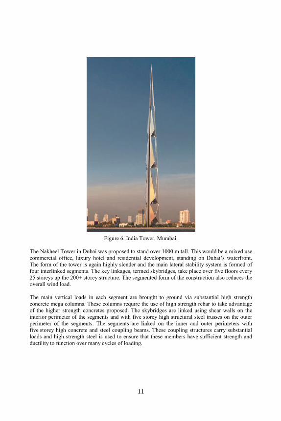
Figure 6. India Tower, Mumbai.
The Nakheel Tower in Dubai was proposed to stand over 1000 m tall. This would be a mixed use
commercial office, luxury hotel and residential development, standing on Dubai’s waterfront.
The form of the tower is again highly slender and the main lateral stability system is formed of
four interlinked segments. The key linkages, termed skybridges, take place over five floors every
25 storeys up the 200+ storey structure. The segmented form of the construction also reduces the
overall wind load.
The main vertical loads in each segment are brought to ground via substantial high strength
concrete mega columns. These columns require the use of high strength rebar to take advantage
of the higher strength concretes proposed. The skybridges are linked using shear walls on the
interior perimeter of the segments and with five storey high structural steel trusses on the outer
perimeter of the segments. The segments are linked on the inner and outer perimeters with
five storey high concrete and steel coupling beams. These coupling structures carry substantial
loads and high strength steel is used to ensure that these members have sufficient strength and
ductility to function over many cycles of loading.
11
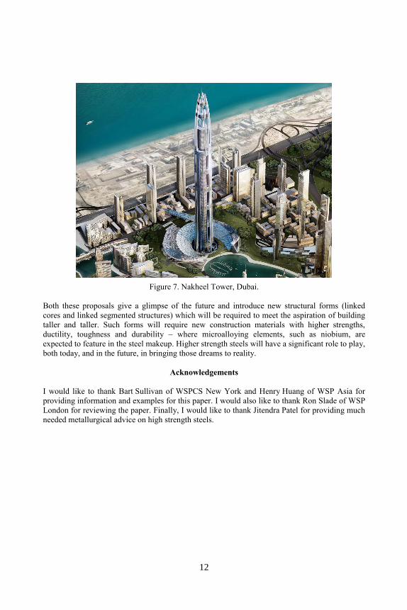
Figure 7. Nakheel Tower, Dubai.
Both these proposals give a glimpse of the future and introduce new structural forms (linked
cores and linked segmented structures) which will be required to meet the aspiration of building
taller and taller. Such forms will require new construction materials with higher strengths,
ductility, toughness and durability – where microalloying elements, such as niobium, are
expected to feature in the steel makeup. Higher strength steels will have a significant role to play,
both today, and in the future, in bringing those dreams to reality.
Acknowledgements
I would like to thank Bart Sullivan of WSPCS New York and Henry Huang of WSP Asia for
providing information and examples for this paper. I would also like to thank Ron Slade of WSP
London for reviewing the paper. Finally, I would like to thank Jitendra Patel for providing much
needed metallurgical advice on high strength steels.
12