Embed Size (px)
Citation preview
High recovery recycling route of WEEE: The potential of pyrolysis
Proceedings of EMC 2015 1
High recovery recycling route of WEEE: The
potential of pyrolysis
Diaz, F; Florez S.; Friedrich, B.
IME Process Metallurgy and Metal Recycling, RWTH Aachen University
Intzestraße 3
D-52056 Aachen, Germany
Keywords: WEEE, autothermic process, pyrolysis, vacuum distillation, aluminium, Copper.
Abstract
An optimized recycling route is being designed to recycle complex metallic materials such as waste
electric and electronic equipment (WEEE). The new proposed methodology overcomes huge
challenges like improved recovery of valuable metals, better control of hazardous substances,
improved process control and recycling capacity. The recycling process for E-Scrap would be
developed in such way that no waste would be obtained and all products and by-products could be
saleable materials.
In this work pyrolysis is introduced as a pre-processing method, which stands out among current
standard processing paths due to its versatility when treating two different streams from high metal
containing WEEE. From one side the method achieves a better separation of the metallic from the
non-metallic fraction when dealing with PCBs. An increase of 10% in the beneficiation of the
metal, while the production of solid and a liquid of organic nature, with high potential as fuel and
chemical feedstock are valuable characteristics. Alternatively, it favours the separation of plastic
material found in the metallic fraction as a requirement to a farther separation in order to produce
individual fractions rich in Cu and Al with purities above 90%.
1 Introduction
According to the WEEE directive 2002/96/EG, WEEE is the end of life of products of “Electric and
Electronic Equipment”. It is applied to devices which use electric currents or electromagnetic fields
to work, as well as, equipment used for generation, transfer and measurement of such currents and
fields not exceeding an AC voltage of 1000V and a DC voltage of 1500V. [1]
Composition of WEEE can vary from time to time due to diversity of WEEE. The WEEE Directive
2012/19/EU subdivides the WEEE into ten categories: 1. Large household appliances, 2. Small
household appliances, 3. Information technology and telecommunications equipment, 4. Consumer
equipment, 5. Lightning equipment, 6.Electrical and electronics tools, 7. Toys, 8. Medical
equipment systems, 9. Monitoring and control instruments, 10. Automatic dispensers. However,
Diaz, F; Florez S.; Friedrich, B.
Proceedings of EMC 2015 2
generally speaking electronic scrap roughly consists of 15-30% plastics, 40-50% ceramics and 20-
30% metals like copper, aluminum and iron. [2] The metallic fraction in printed circuits boards
(PCBs) consists of approximately 16% copper, 4% tin-lead, 3% iron and ferrite, 2% nickel, 0.05%
silver, 0.03% gold, 0.01% palladium and even metals such as tantalum are found which are
normally bonded to a ceramic or plastic cover. [3][4]
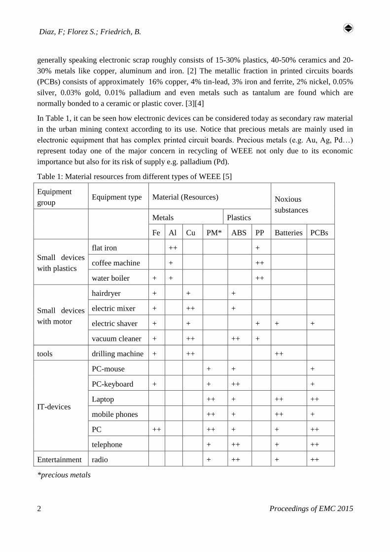
In Table 1, it can be seen how electronic devices can be considered today as secondary raw material
in the urban mining context according to its use. Notice that precious metals are mainly used in
electronic equipment that has complex printed circuit boards. Precious metals (e.g. Au, Ag, Pd…)
represent today one of the major concern in recycling of WEEE not only due to its economic
importance but also for its risk of supply e.g. palladium (Pd).
Table 1: Material resources from different types of WEEE [5]
Equipment
group Equipment type Material (Resources) Noxious
substances
Metals Plastics
Fe Al Cu PM* ABS PP Batteries PCBs
Small devices
with plastics
flat iron ++ +
coffee machine + ++
water boiler + + ++
Small devices
with motor
hairdryer + + +
electric mixer + ++ +
electric shaver + + + + +
vacuum cleaner + ++ ++ +
tools drilling machine + ++ ++
IT-devices
PC-mouse + + +
PC-keyboard + + ++ +
Laptop ++ + ++ ++
mobile phones ++ + ++ +
PC ++ ++ + + ++
telephone + ++ + ++
Entertainment radio + ++ + ++
*precious metals
High recovery recycling route of WEEE: The potential of pyrolysis
Proceedings of EMC 2015 3
2 Theoretical background for the planned recycling process
2.1 Preprocessing of WEEE
Many are the attempts to stablish a certain path for WEEE recycling. This is however not easy since
WEEE is a mixture of different components which require special pre-processing techniques for its
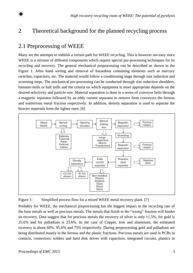
recycling and recovery. The general mechanical preprocessing can be described as shown in the
Figure 1. After hand sorting and removal of hazardous containing elements such as mercury
switches, capacitors, etc. The material would follow a conditioning stage through size reduction and
screening steps. The mechanical pre-processing can be conducted through size reduction shredders,
hammer-mills or ball mills and the criteria on which equipment is more appropriate depends on the
desired selectivity and particle size. Material separation is done in a series of conveyor belts through
a magnetic separator followed by an eddy current separator to remove from conveyors the ferrous
and nonferrous metal fraction respectively. In addition, density separation is used to separate the
heavier materials from the lighter ones. [6]
Figure 1: Simplified process flow for a mixed WEEE metal recovery plant. [7]
Probably for WEEE, the mechanical preprocessing has the biggest impact in the recycling rate of
the base metals as well as precious metals. The metals that finish in the “wrong” fraction will hinder
its recovery. Data suggest that for precious metals the recovery of silver is only 11.5%, for gold is
25.6% and for palladium is 25.6%. In the case of Copper, iron and aluminum, the estimated
recovery is about 60%, 95.6% and 75% respectively. During preprocessing gold and palladium are
being distributed mainly in the ferrous and the plastic fractions. Precious metals are used in PCBs in
contacts, connectors, solders and hard disk drives with capacitors, integrated circuits, plastics in
Diaz, F; Florez S.; Friedrich, B.
Proceedings of EMC 2015 4
PCBs tracks, interboard layers, etc. Therefore, after shredding the small pieces that still contain a
magnetic part are pulled out during the strong magnetic separation. On the other hand, a strong
shredding process disperses the PM in the dust which is not further treated for a recovery but
mainly dumped. [8]
2.2 Basics of pyrolysis
Pyrolysis is a process that involves chemical and thermal decomposition under absence of oxygen
with λ=0, where λ is the ratio of the total amount of air in the system to the air required for total
stoichiometric combustion. Organics are mainly degraded to cokes and gaseous components: [11]
Organic(s) = Cokes(s) + gaseous Components (1)
However, the gaseous components could be also divided in non-condensable gases and condensable
gases that are transformed into a liquid/oil state (made up of naphthenes, aromatics, paraffin and
olefins). Pyrolysis finds its main application in the thermal decomposition of polymers, where the
principal objective is to break down the macromolecular structure of polymeric materials into
smaller molecules, known as monomers or oligomers. The thermal decomposition of polymers can
be classified as depolymerization, random decomposition and mid chain degradation. Extensive
studies have been done in this field and therefore the mechanism that allows this decomposition has
in general the following possible mechanisms:
I) End-chain scission or depolymerization: the breaking of the polymer takes place, starting
from the end groups resulting in successive groups of monomers. It is widely consider as the main
method for plastic pyrolysis.
II) Random-chain scission: after the polymer is broken up from the end groups, the polymer
chain starts breaking up randomly along the main chain into fragments of unequal length.
III) Chain-stripping: any external additive or reactive substitutes and side groups are eliminated
from the polymer chain. The yield is a cracking product by one side and a charing polymer on the
other.
IV) Cross-linking: generation of a chain network, which is very common mechanism for
thermosetting polymers when heated.
The way in which the polymer is decomposed and the products generated are until a certain extent,
related to the bond dissociation energies, the chain defects of the polymer and the presence of
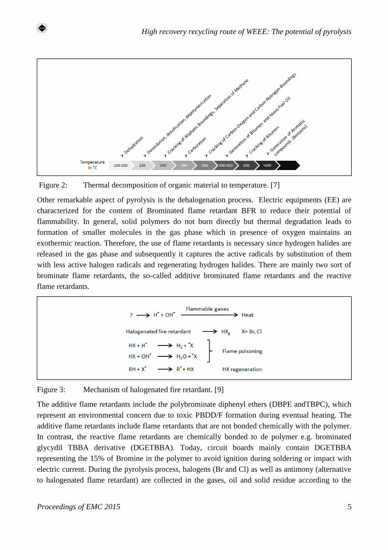
additives in the chain such as halogens and heteroatoms. In figure 2 is shown the thermal
degradation of the organic material upon temperature. [9] [10]
High recovery recycling route of WEEE: The potential of pyrolysis
Proceedings of EMC 2015 5
Figure 2: Thermal decomposition of organic material to temperature. [7]
Other remarkable aspect of pyrolysis is the dehalogenation process. Electric equipments (EE) are
characterized for the content of Brominated flame retardant BFR to reduce their potential of
flammability. In general, solid polymers do not burn directly but thermal degradation leads to
formation of smaller molecules in the gas phase which in presence of oxygen maintains an
exothermic reaction. Therefore, the use of flame retardants is necessary since hydrogen halides are
released in the gas phase and subsequently it captures the active radicals by substitution of them
with less active halogen radicals and regenerating hydrogen halides. There are mainly two sort of
brominate flame retardants, the so-called additive brominated flame retardants and the reactive
flame retardants.
Figure 3: Mechanism of halogenated fire retardant. [9]
The additive flame retardants include the polybrominate diphenyl ethers (DBPE andTBPC), which
represent an environmental concern due to toxic PBDD/F formation during eventual heating. The
additive flame retardants include flame retardants that are not bonded chemically with the polymer.
In contrast, the reactive flame retardants are chemically bonded to de polymer e.g. brominated
glycydil TBBA derivative (DGETBBA). Today, circuit boards mainly contain DGETBBA
representing the 15% of Bromine in the polymer to avoid ignition during soldering or impact with
electric current. During the pyrolysis process, halogens (Br and Cl) as well as antimony (alternative
to halogenated flame retardant) are collected in the gases, oil and solid residue according to the

Diaz, F; Florez S.; Friedrich, B.
Proceedings of EMC 2015 6
substrate and on pyrolysis conditions. Formed HBr could be eventually recovered from the gas
phase for re-use and condensed inorganic halides in the oil can be extracted from oil by washing.
Despite the advantage of strong reduction of halogens from the solid materials there is still a major
concern of appropriated treatment of oil and gases due to the add value for these complex
treatments to the total recycling process.[9]
Figure 4: Instance of a flame retardant’s Polymer chain: DGETBBA. [9]
Figure 5: PCDD/F and PBDD/F. [9]
3 Experimental work
As described in Table 1, a special focus would be done in electronic scrap that contains precious
metals. The standard mechanical preprocessing of WEEE (see Figure 1) would be applied to
devices that do not contain printed circuit boards. However, for devices that contain PCBs greater
than 10 cm2, a separation is to be done either at the manual separation stage or after pre-shredding
to avoid grinding of PCBs and to produce a rich fraction of them. For the scope of this work PCBs
and metal fraction containing plastic insulation material are of relevance. For both fractions
pyrolysis is used as a pre-processing method, allowing a better separation of the metallic and non-
metallic fraction in the case of PCBs and alternatively favours the separation of plastic material
found in the metallic fraction.
As first instance PCBs will be subjected to pyrolysis experiments and afterwards the solid fraction
undergo a grinding step to obtain the metallic and non-metallic portions. These fractions can be
latter conditioned and agglomerated in order to obtain pellets. The advantage of doing so is the
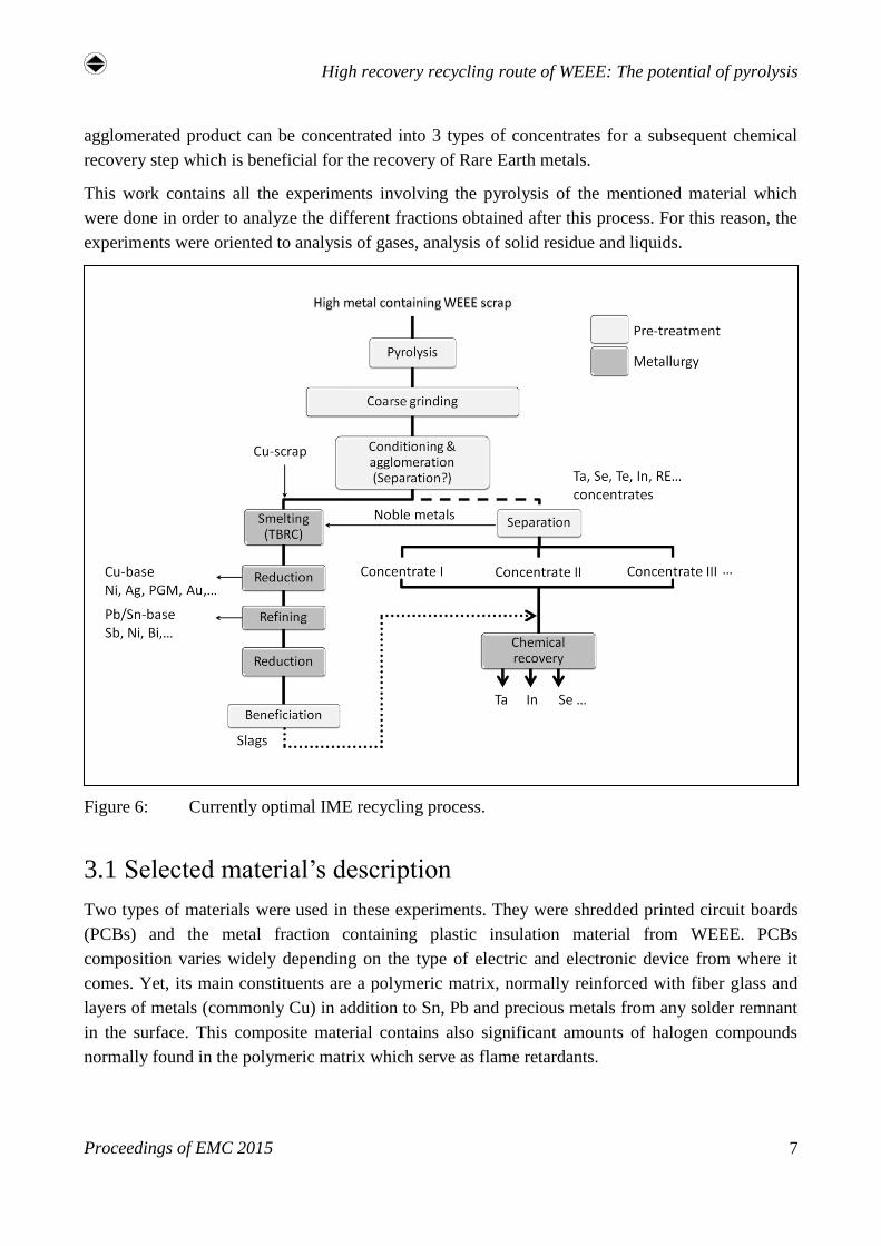
possibility to obtain an agglomerated material with an autothermic property. As seen on figure 6 the
agglomerated product after pyrolysis can be treated with a direct smelting process in order to melt
the Cu-base components and later refine the Pb/Sn subproducts. Parallel to this process the
High recovery recycling route of WEEE: The potential of pyrolysis
Proceedings of EMC 2015 7
agglomerated product can be concentrated into 3 types of concentrates for a subsequent chemical
recovery step which is beneficial for the recovery of Rare Earth metals.
This work contains all the experiments involving the pyrolysis of the mentioned material which
were done in order to analyze the different fractions obtained after this process. For this reason, the
experiments were oriented to analysis of gases, analysis of solid residue and liquids.
Figure 6: Currently optimal IME recycling process.
3.1 Selected material’s description
Two types of materials were used in these experiments. They were shredded printed circuit boards
(PCBs) and the metal fraction containing plastic insulation material from WEEE. PCBs
composition varies widely depending on the type of electric and electronic device from where it
comes. Yet, its main constituents are a polymeric matrix, normally reinforced with fiber glass and
layers of metals (commonly Cu) in addition to Sn, Pb and precious metals from any solder remnant
in the surface. This composite material contains also significant amounts of halogen compounds
normally found in the polymeric matrix which serve as flame retardants.
Diaz, F; Florez S.; Friedrich, B.
Proceedings of EMC 2015 8
By another hand, the metallic fraction is also very heterogeneous material and its composition is
usually dependent upon the type of EEE group it derives from. In principle, Cu, Al and Fe appear as
the metals with the greatest portion. Therefore, some typical alloys such as CuZn38Pb or AlSi12 are
commonly found in this group. The metallic fraction is also characterized because the metals are
found as wires and plates of different sizes. In most of the cases the cables possess a plastic
insulation which interferes in a further density separation process when it is desired to obtain a
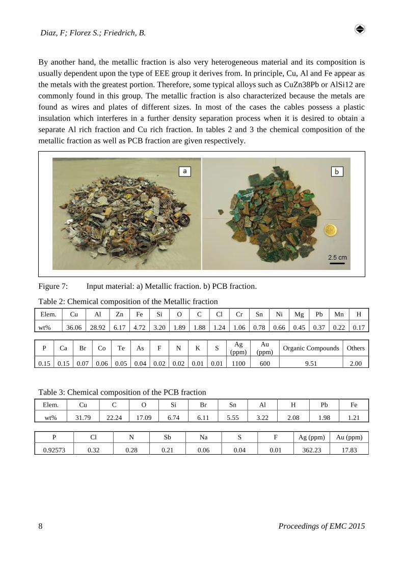
separate Al rich fraction and Cu rich fraction. In tables 2 and 3 the chemical composition of the
metallic fraction as well as PCB fraction are given respectively.
Figure 7: Input material: a) Metallic fraction. b) PCB fraction.
Table 2: Chemical composition of the Metallic fraction
Elem. Cu Al Zn Fe Si O C Cl Cr Sn Ni Mg Pb Mn H
wt% 36.06 28.92 6.17 4.72 3.20 1.89 1.88 1.24 1.06 0.78 0.66 0.45 0.37 0.22 0.17
Table 3: Chemical composition of the PCB fraction
Elem. Cu C O Si Br Sn Al H Pb Fe
wt% 31.79 22.24 17.09 6.74 6.11 5.55 3.22 2.08 1.98 1.21
P Ca Br Co Te As F N K S Ag
(ppm)
Au
(ppm) Organic Compounds Others
0.15 0.15 0.07 0.06 0.05 0.04 0.02 0.02 0.01 0.01 1100 600 9.51 2.00
P Cl N Sb Na S F Ag (ppm) Au (ppm)
0.92573 0.32 0.28 0.21 0.06 0.04 0.01 362.23 17.83
High recovery recycling route of WEEE: The potential of pyrolysis
Proceedings of EMC 2015 9
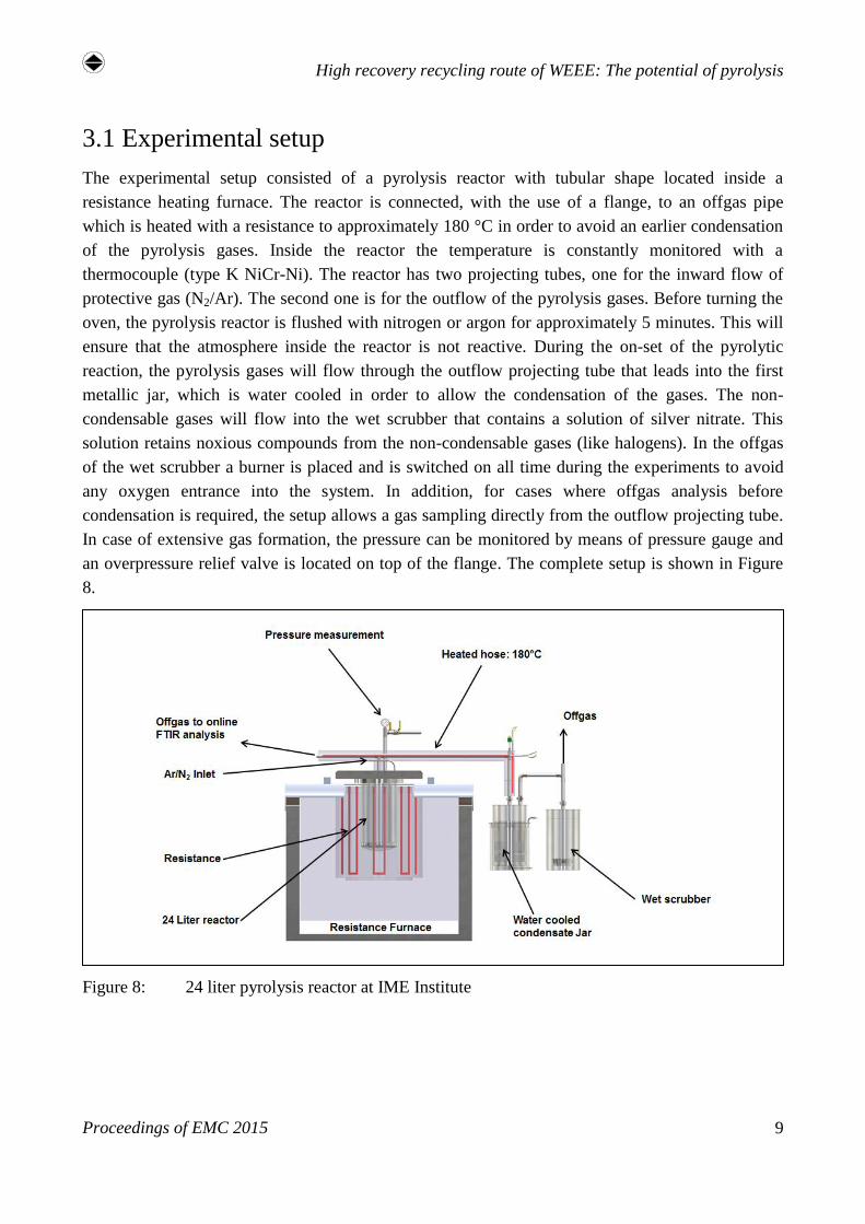
3.1 Experimental setup
The experimental setup consisted of a pyrolysis reactor with tubular shape located inside a
resistance heating furnace. The reactor is connected, with the use of a flange, to an offgas pipe
which is heated with a resistance to approximately 180 °C in order to avoid an earlier condensation
of the pyrolysis gases. Inside the reactor the temperature is constantly monitored with a
thermocouple (type K NiCr-Ni). The reactor has two projecting tubes, one for the inward flow of
protective gas (N2/Ar). The second one is for the outflow of the pyrolysis gases. Before turning the
oven, the pyrolysis reactor is flushed with nitrogen or argon for approximately 5 minutes. This will
ensure that the atmosphere inside the reactor is not reactive. During the on-set of the pyrolytic
reaction, the pyrolysis gases will flow through the outflow projecting tube that leads into the first
metallic jar, which is water cooled in order to allow the condensation of the gases. The non-
condensable gases will flow into the wet scrubber that contains a solution of silver nitrate. This
solution retains noxious compounds from the non-condensable gases (like halogens). In the offgas
of the wet scrubber a burner is placed and is switched on all time during the experiments to avoid
any oxygen entrance into the system. In addition, for cases where offgas analysis before
condensation is required, the setup allows a gas sampling directly from the outflow projecting tube.
In case of extensive gas formation, the pressure can be monitored by means of pressure gauge and
an overpressure relief valve is located on top of the flange. The complete setup is shown in Figure
8.
Figure 8: 24 liter pyrolysis reactor at IME Institute
Diaz, F; Florez S.; Friedrich, B.
Proceedings of EMC 2015 10
4 Results and discussion
4.1 Pyrolysis of the metallic fraction
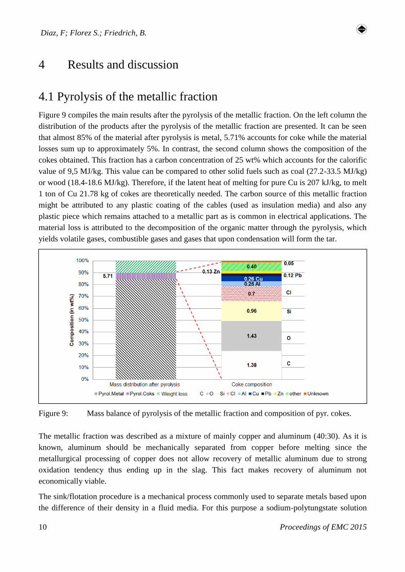
Figure 9 compiles the main results after the pyrolysis of the metallic fraction. On the left column the
distribution of the products after the pyrolysis of the metallic fraction are presented. It can be seen
that almost 85% of the material after pyrolysis is metal, 5.71% accounts for coke while the material
losses sum up to approximately 5%. In contrast, the second column shows the composition of the
cokes obtained. This fraction has a carbon concentration of 25 wt% which accounts for the calorific
value of 9,5 MJ/kg. This value can be compared to other solid fuels such as coal (27.2-33.5 MJ/kg)
or wood (18.4-18.6 MJ/kg). Therefore, if the latent heat of melting for pure Cu is 207 kJ/kg, to melt
1 ton of Cu 21.78 kg of cokes are theoretically needed. The carbon source of this metallic fraction
might be attributed to any plastic coating of the cables (used as insulation media) and also any
plastic piece which remains attached to a metallic part as is common in electrical applications. The
material loss is attributed to the decomposition of the organic matter through the pyrolysis, which
yields volatile gases, combustible gases and gases that upon condensation will form the tar.
Figure 9: Mass balance of pyrolysis of the metallic fraction and composition of pyr. cokes.
The metallic fraction was described as a mixture of mainly copper and aluminum (40:30). As it is
known, aluminum should be mechanically separated from copper before melting since the
metallurgical processing of copper does not allow recovery of metallic aluminum due to strong
oxidation tendency thus ending up in the slag. This fact makes recovery of aluminum not
economically viable.
The sink/flotation procedure is a mechanical process commonly used to separate metals based upon
the difference of their density in a fluid media. For this purpose a sodium-polytungstate solution
High recovery recycling route of WEEE: The potential of pyrolysis
Proceedings of EMC 2015 11
(3Na2WO4·9WO3·H2O, ⍴ = 2.82 g/cm) was utilized to separate aluminum from copper as they
were the most abundant portion in the metallic fraction. From the process is expected that the
heavier metals will sink, while the lighter will float in the surface of the liquid.
It was found that subjecting the metallic fraction to pyrolysis permits an easy separation of organics
from the metals. This fact is of importance since otherwise the density separation would not work as
expected due to an alteration of the buoyancy force of heavier metals. In other words, the buoyancy
force of the plastic recovering the metal is higher than the gravity force of the heavy metal
necessary to settle in the bottom of the liquid. Therefore by removal of the organics density
separation can operate under normal conditions obtaining a heavy metal fraction (rich in Cu) and a
light metal fraction (rich in Al).
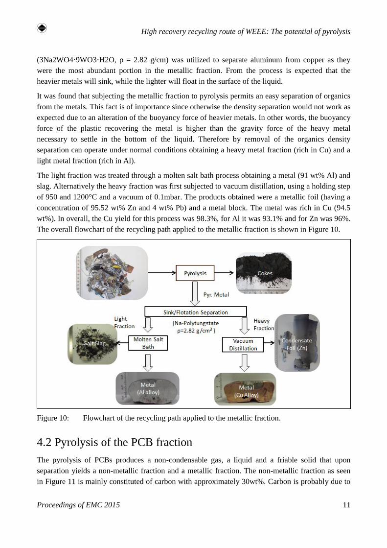
The light fraction was treated through a molten salt bath process obtaining a metal (91 wt% Al) and
slag. Alternatively the heavy fraction was first subjected to vacuum distillation, using a holding step
of 950 and 1200°C and a vacuum of 0.1mbar. The products obtained were a metallic foil (having a
concentration of 95.52 wt% Zn and 4 wt% Pb) and a metal block. The metal was rich in Cu (94.5
wt%). In overall, the Cu yield for this process was 98.3%, for Al it was 93.1% and for Zn was 96%.
The overall flowchart of the recycling path applied to the metallic fraction is shown in Figure 10.
Figure 10: Flowchart of the recycling path applied to the metallic fraction.
4.2 Pyrolysis of the PCB fraction
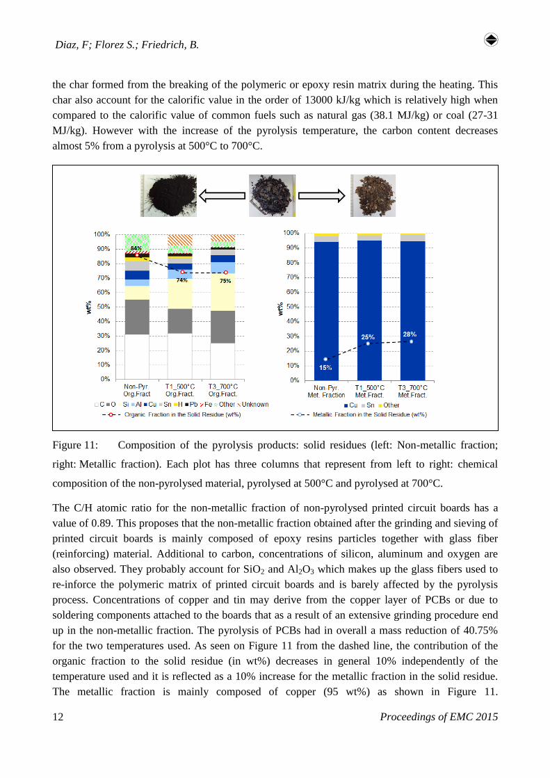
The pyrolysis of PCBs produces a non-condensable gas, a liquid and a friable solid that upon
separation yields a non-metallic fraction and a metallic fraction. The non-metallic fraction as seen
in Figure 11 is mainly constituted of carbon with approximately 30wt%. Carbon is probably due to
Diaz, F; Florez S.; Friedrich, B.
Proceedings of EMC 2015 12
the char formed from the breaking of the polymeric or epoxy resin matrix during the heating. This
char also account for the calorific value in the order of 13000 kJ/kg which is relatively high when
compared to the calorific value of common fuels such as natural gas (38.1 MJ/kg) or coal (27-31
MJ/kg). However with the increase of the pyrolysis temperature, the carbon content decreases
almost 5% from a pyrolysis at 500°C to 700°C.
Figure 11: Composition of the pyrolysis products: solid residues (left: Non-metallic fraction;
right: Metallic fraction). Each plot has three columns that represent from left to right: chemical
composition of the non-pyrolysed material, pyrolysed at 500°C and pyrolysed at 700°C.
The C/H atomic ratio for the non-metallic fraction of non-pyrolysed printed circuit boards has a
value of 0.89. This proposes that the non-metallic fraction obtained after the grinding and sieving of
printed circuit boards is mainly composed of epoxy resins particles together with glass fiber
(reinforcing) material. Additional to carbon, concentrations of silicon, aluminum and oxygen are
also observed. They probably account for SiO2 and Al2O3 which makes up the glass fibers used to
re-inforce the polymeric matrix of printed circuit boards and is barely affected by the pyrolysis
process. Concentrations of copper and tin may derive from the copper layer of PCBs or due to
soldering components attached to the boards that as a result of an extensive grinding procedure end
up in the non-metallic fraction. The pyrolysis of PCBs had in overall a mass reduction of 40.75%
for the two temperatures used. As seen on Figure 11 from the dashed line, the contribution of the
organic fraction to the solid residue (in wt%) decreases in general 10% independently of the
temperature used and it is reflected as a 10% increase for the metallic fraction in the solid residue.
The metallic fraction is mainly composed of copper (95 wt%) as shown in Figure 11.
High recovery recycling route of WEEE: The potential of pyrolysis
Proceedings of EMC 2015 13
Concentrations of silver and gold in the range of 200-300 ppm and 10 ppm respectively were also
found.
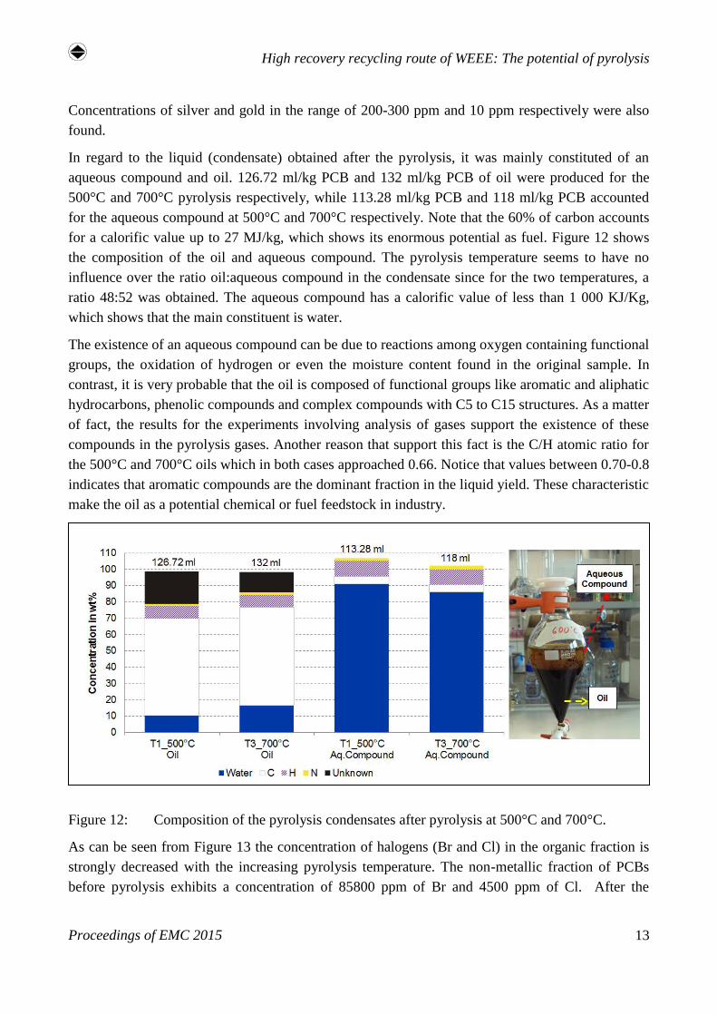
In regard to the liquid (condensate) obtained after the pyrolysis, it was mainly constituted of an
aqueous compound and oil. 126.72 ml/kg PCB and 132 ml/kg PCB of oil were produced for the
500°C and 700°C pyrolysis respectively, while 113.28 ml/kg PCB and 118 ml/kg PCB accounted
for the aqueous compound at 500°C and 700°C respectively. Note that the 60% of carbon accounts
for a calorific value up to 27 MJ/kg, which shows its enormous potential as fuel. Figure 12 shows
the composition of the oil and aqueous compound. The pyrolysis temperature seems to have no
influence over the ratio oil:aqueous compound in the condensate since for the two temperatures, a
ratio 48:52 was obtained. The aqueous compound has a calorific value of less than 1 000 KJ/Kg,
which shows that the main constituent is water.
The existence of an aqueous compound can be due to reactions among oxygen containing functional
groups, the oxidation of hydrogen or even the moisture content found in the original sample. In
contrast, it is very probable that the oil is composed of functional groups like aromatic and aliphatic
hydrocarbons, phenolic compounds and complex compounds with C5 to C15 structures. As a matter
of fact, the results for the experiments involving analysis of gases support the existence of these
compounds in the pyrolysis gases. Another reason that support this fact is the C/H atomic ratio for
the 500°C and 700°C oils which in both cases approached 0.66. Notice that values between 0.70-0.8
indicates that aromatic compounds are the dominant fraction in the liquid yield. These characteristic
make the oil as a potential chemical or fuel feedstock in industry.
Figure 12: Composition of the pyrolysis condensates after pyrolysis at 500°C and 700°C.
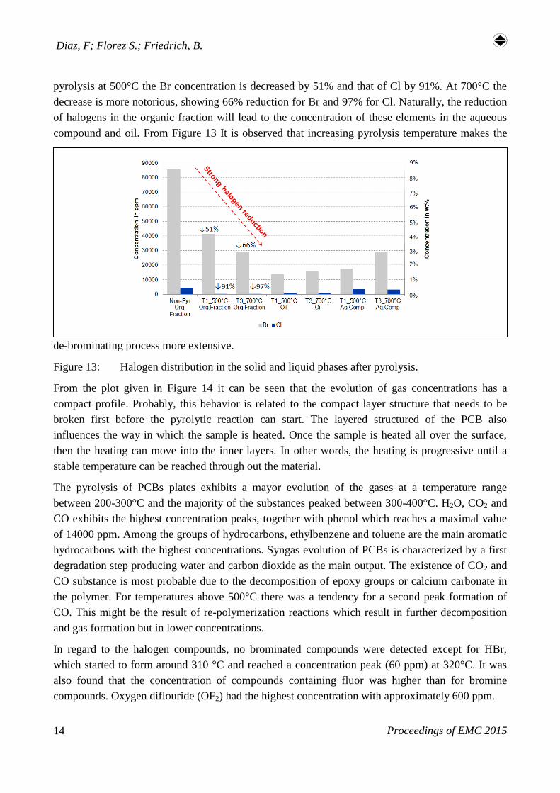
As can be seen from Figure 13 the concentration of halogens (Br and Cl) in the organic fraction is
strongly decreased with the increasing pyrolysis temperature. The non-metallic fraction of PCBs
before pyrolysis exhibits a concentration of 85800 ppm of Br and 4500 ppm of Cl. After the
Diaz, F; Florez S.; Friedrich, B.
Proceedings of EMC 2015 14
pyrolysis at 500°C the Br concentration is decreased by 51% and that of Cl by 91%. At 700°C the
decrease is more notorious, showing 66% reduction for Br and 97% for Cl. Naturally, the reduction
of halogens in the organic fraction will lead to the concentration of these elements in the aqueous
compound and oil. From Figure 13 It is observed that increasing pyrolysis temperature makes the
de-brominating process more extensive.
Figure 13: Halogen distribution in the solid and liquid phases after pyrolysis.
From the plot given in Figure 14 it can be seen that the evolution of gas concentrations has a
compact profile. Probably, this behavior is related to the compact layer structure that needs to be
broken first before the pyrolytic reaction can start. The layered structured of the PCB also
influences the way in which the sample is heated. Once the sample is heated all over the surface,
then the heating can move into the inner layers. In other words, the heating is progressive until a
stable temperature can be reached through out the material.
The pyrolysis of PCBs plates exhibits a mayor evolution of the gases at a temperature range
between 200-300°C and the majority of the substances peaked between 300-400°C. H2O, CO2 and
CO exhibits the highest concentration peaks, together with phenol which reaches a maximal value
of 14000 ppm. Among the groups of hydrocarbons, ethylbenzene and toluene are the main aromatic
hydrocarbons with the highest concentrations. Syngas evolution of PCBs is characterized by a first
degradation step producing water and carbon dioxide as the main output. The existence of CO2 and
CO substance is most probable due to the decomposition of epoxy groups or calcium carbonate in
the polymer. For temperatures above 500°C there was a tendency for a second peak formation of
CO. This might be the result of re-polymerization reactions which result in further decomposition
and gas formation but in lower concentrations.
In regard to the halogen compounds, no brominated compounds were detected except for HBr,
which started to form around 310 °C and reached a concentration peak (60 ppm) at 320°C. It was
also found that the concentration of compounds containing fluor was higher than for bromine
compounds. Oxygen diflouride (OF2) had the highest concentration with approximately 600 ppm.

High recovery recycling route of WEEE: The potential of pyrolysis
Proceedings of EMC 2015 15
Judging from the results, it can be said that a pyrolysis conducted at 400°C is sufficient to start the
decomposition of the printed circuit board plates.
Figure 14: evolution of the syngas during pyrolysis.
5 Conclusion
Pyrolysis is a process that involves chemical and thermal decomposition which converts WEEE in
three main products: non-condensable gas fraction, liquid fraction (made up of naphthenes,
aromatics, paraffin and olefins) and solid residue. Oils and gases can be used as chemical
feedstocks or fuels due to its high calorific value, whereas metals, inorganic fillers, organic carbon
and glass fibers get accumulated in the solid fraction. The resulting solid material makes the
separation of organics, metals and glass fiber fractions much easier and consequently the recycling
of each fraction more viable. In figure 15 and Table 3, the standard process is contrasted with the
pyrolysis based processing method applied to the two selected materials given in this report.
Based on this work, it was found that a recycling process of complex metallic waste involving a
pyrolysis followed by a density separation allows recovery of Aluminum with a 93% of
effectiveness from copper containing scraps, which by other means would be lost in the slag during
the metallurgical process. In addition, the produced pyrolysed cokes with a carbon concentration of
25 wt% that accounts for the calorific value of 9,5 MJ/kg, have an enormous potential as alternative
fuel in the pyrometallurgical recycling process of copper. In regard to the printed circuit boards it
was concluded that a pyrolysis is a viable process with no material losses to produce a liquid fuel
and combustible gases, while the solid residue due to its friability after pyrolysis allows an
Diaz, F; Florez S.; Friedrich, B.
Proceedings of EMC 2015 16
extensive beneficiation of the metals, in addition to a mass reduction of about 40%. It was also
concluded that pyrolysis permits removal of about 60% of the bromine and more than 95% of the
chlorine from non-metallic fraction in PCBs, which otherwise would be fumed in the smelter
producing acidic gases that harm the refractory material of the furnace at high temperatures.
However, accumulation of halogens in the condensate makes its treatment rather complex and
expensive. An alternative to condensation would be to perform combustion of the produced syngas
before condensation takes place. The liberated energy could be used as a part of the consumed
energy during the pyrolysis itself which would decrease strongly the operating cost of the process.
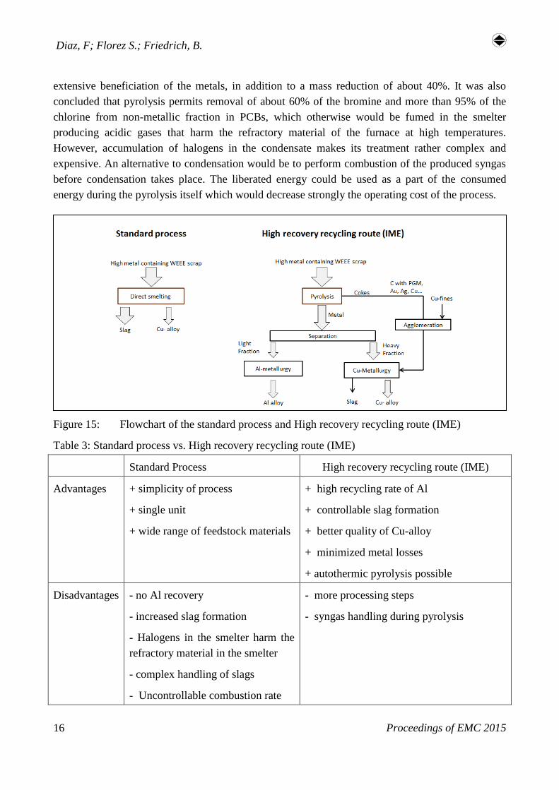
Figure 15: Flowchart of the standard process and High recovery recycling route (IME)
Table 3: Standard process vs. High recovery recycling route (IME)
Standard Process High recovery recycling route (IME)
Advantages + simplicity of process
+ single unit
+ wide range of feedstock materials
+ high recycling rate of Al
+ controllable slag formation
+ better quality of Cu-alloy
+ minimized metal losses
+ autothermic pyrolysis possible
Disadvantages - no Al recovery
- increased slag formation
- Halogens in the smelter harm the
refractory material in the smelter
- complex handling of slags
- Uncontrollable combustion rate
- more processing steps
- syngas handling during pyrolysis
High recovery recycling route of WEEE: The potential of pyrolysis
Proceedings of EMC 2015 17
6 Summary and Outlook
Since the early 90s the concern for WEEE recycling has grown in importance due to fast innovation
and replacement of electrical and electronic equipment. However, the take back and treatment
systems for WEEE have in practice a high degree of complexity since the material composition
varies widely. The standard recycling technique for WEEE is the mechanical processing that
includes disassembling, grinding and sorting. The metallic fraction from this product can be
optimally treated with a remelting process. However, metals like Al, Zn and Pb cannot be safely
recovered. The organic fraction (found in printed circuit boards and plastics) cannot be treated
together with the metallic one owing to an elevated heat of combustion, high concentration of
halogen compounds and in general making more complex the preprocessing stage.
Based on this work, it was found that a process involving a pyrolysis of the metallic fraction
followed by a density separation firstly allows a separation of the pyrolised plastics from the metal
in addition to obtaining a separate portion rich in metallic aluminum. Additionally, a heavy fraction
was also obtained which after a vacuum distillation process allowed the recovery of a metal foil
with high zinc concentration (96 wt %) and a Cu-base alloy. Both main fractions (Al & Cu) exhibit
purity greater than 90% making them saleable products for Al and Cu industry. Note that the
metallic yield of copper, aluminum and zinc was 98.3%, 93.1% and 96 % respectively.
In regard to the printed circuit boards it was observed that a pyrolysis is a viable process with no
losses to produce a fuel with a high calorific value (27 MJ/kg), combustible gases with a potential
use as combustible gas or chemical feedstock and a solid residue with an extensive beneficiation of
the metal. This is the result of a mass reduction of about 40% in the solid residue. In addition, it was
found that pyrolysis can be used as a strong dehalogenation process of plastic containing wastes.
For this particular work a removal of about 60% and 97% of bromine and chlorine was respectively
achieved. Finally, after experimental validation, it was observed that a pyrolysis temperature above
400°C does not exhibit a remarkable difference in respect to the peaks of main compounds in the
syngas formation.
After preliminary experiments using shredded PCBs will follow a proof of principle of the proposed
recycling process (Figure 6) applied to PCBs from mobile phones, contrasted in parallel with the
current standards in mechanical pretreatment. For the following, a special focus on base metals and
precious metals is to be done. Subsequently, a thermodynamic assessment of the non-metallic
fraction produced after pyrolysis will be carried out using the software Factsage. The simulations
will be validated with experiments in lab scale. Finally, it will be necessary to define the
metallurgical process window in order to conduct an autothermic melting process using a top blown
rotary converter TBRC. The parameters that will define this process window are the chemical
composition of metallic fraction, type of agglomeration of the non-metallic fraction, use of
additives and inclusion of other copper secondary raw materials.
Diaz, F; Florez S.; Friedrich, B.
Proceedings of EMC 2015 18
References
[1] J. Huisman, F. Magalini, R. Kuehr, C. Maurer: 2008 Review of Directive 2002/96 on Waste
Electrical and Electronic Equipment (WEEE) –Final report, p 228-256, 2008.
[2] Chancerel, P., Rotter, S., 2009. Recycling-oriented characterization of small waste electrical
and electronic equipment. Waste Management 29, 2336-2352.
[3] Canal Marques, A., Cabrera, J-M., de Fraga Malfatti, C., 2013. Printed circuit boards: A
review on the perspective of sustainability. Journal of Environmental Management 131, 298-
306.
[4] Chen, M., Wang, J., Chen, H., Ogunseitan, O. A., Zhang, M., Zang, H., Hu, J., 2013.
Electronic Waste Dissasembly with industrial Waste Heat. Environmental Science and
Technology 47, 12409-12416.
[5] Hans Martens, “Recyclingtechnik: Fachbuch für Lehre und Praxis”, Spektrum Akademischer
Verlang Heidelberg 2011.
[6] Jirang Cui, Eric Forssberg, Mechanical recycling of waste electric and electronic equipment: a
review, Journal of Hazardous Materials B99 (2003), 243–263.
[7] DARREN KELL, Recycling and Recovery, Issues in Environmental Science and Technology,
27 Electronic Waste Managemen,t 2008.
[8] Chancerel, P.; Meskers, C.; Hagelueken, C.; Rotter, V. S. Assessment of precious Metal flow
during preprocessing of waste electrical and electronic. Journal of Industrial Ecology Volume
13, Issue 5, October 2009, Pages: 791‐810.
[9] M.P. Luda, 11 - Pyrolysis of WEEE plastics, In Woodhead Publishing Series in Electronic
and Optical Materials, edited by Vannessa Goodship and Ab Stevels, Woodhead Publishing,
Waste Electrical and Electronic Equipment (WEEE) Handbook, 2012, Pages 239-263.
[10] Scheirs, J., Kaminsky, W. Feedstock Recycling and Pyrolysis of Waste Plastics: Converting
Waste Plastics into Diesel and Other Fuels. Wiley Series in Polymer Science, 2006.
[11] Rumpel, S., die autotherme Wirlschichtpyrolyse zur Erzeugung heizwertreicher
Stützbrennstoffe, Universität Karlsruhe (TH), dissertation.