Embed Size (px)
Citation preview
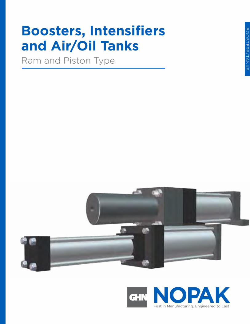
Boosters, Intensifiers and Air/Oil TanksRam and Piston Type
Boosters, Intensifiers and Air/Oil Tanks Ram and Piston Type
BO
OS
TE
RS
/TA
NK
S
172
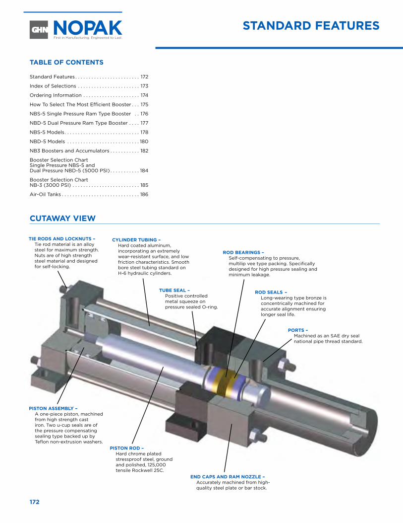
STAndARd FeATuReS
CuTAwAy VIew
ROd SeAlS – Long-wearing type bronze is concentrically machined for accurate alignment ensuring longer seal life.
end CAPS And RAm nOzzle – Accurately machined from high-quality steel plate or bar stock.
ROd BeARIngS – Self-compensating to pressure, multilip vee type packing. Specifically designed for high pressure sealing and minimum leakage.
PISTOn ASSemBly – A one-piece piston, machined from high strength cast iron. Two u-cup seals are of the pressure compensating sealing type backed up by Teflon non-extrusion washers.
CylIndeR TuBIng – Hard coated aluminum, incorporating an extremely wear-resistant surface, and low friction characteristics. Smooth bore steel tubing standard on H-6 hydraulic cylinders.
TuBe SeAl – Positive controlled metal squeeze on pressure sealed O-ring.
PORTS – Machined as an SAE dry seal national pipe thread standard.
TIe ROdS And lOCknuTS – Tie rod material is an alloy steel for maximum strength. Nuts are of high strength steel material and designed for self-locking.
PISTOn ROd – Hard chrome plated stressproof steel, ground and polished, 125,000 tensile Rockwell 25C.
TABle OF COnTenTS
Standard Features . . . . . . . . . . . . . . . . . . . . . . . . 172
Index of Selections . . . . . . . . . . . . . . . . . . . . . . . 173
Ordering Information . . . . . . . . . . . . . . . . . . . . . 174
How To Select The Most Efficient Booster . . . 175
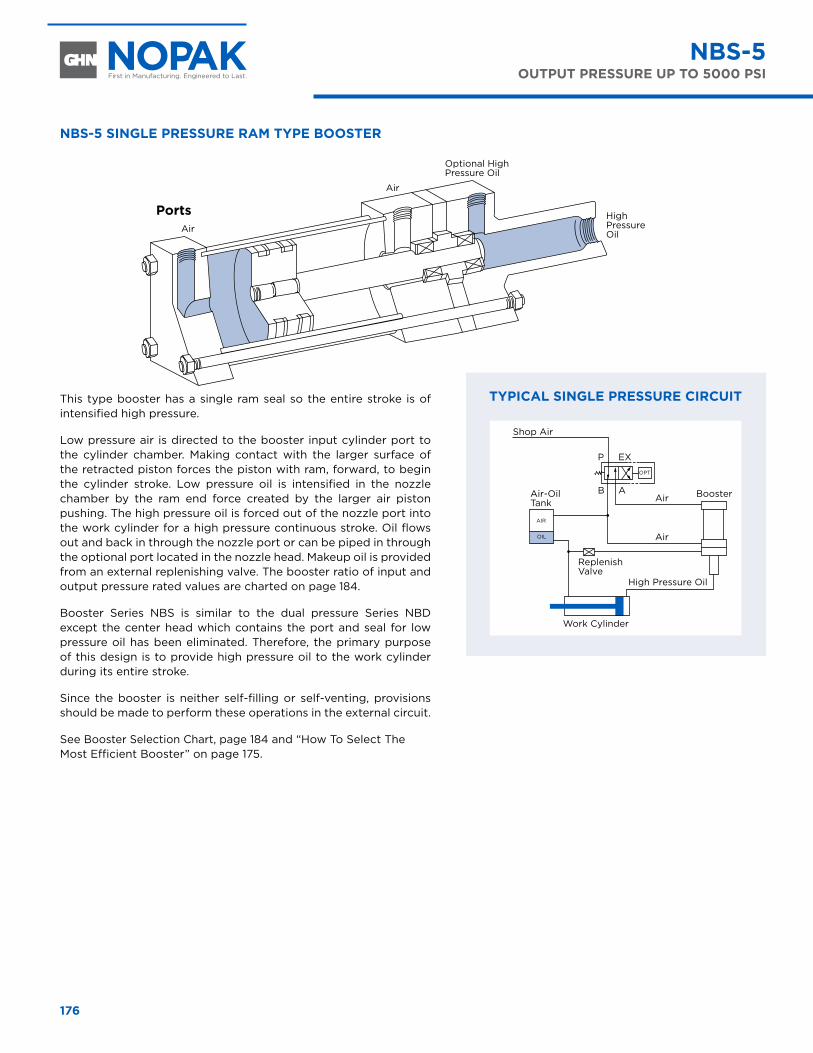
NBS-5 Single Pressure Ram Type Booster . . 176
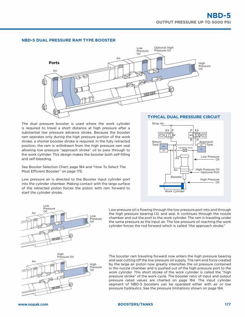
NBD-5 Dual Pressure Ram Type Booster . . . . 177
NBS-5 Models . . . . . . . . . . . . . . . . . . . . . . . . . . . . 178
NBD-5 Models . . . . . . . . . . . . . . . . . . . . . . . . . . . 180
NB3 Boosters and Accumulators . . . . . . . . . . . 182
Booster Selection Chart Single Pressure NBS-5 and Dual Pressure NBD-5 (5000 PSI) . . . . . . . . . . . 184
Booster Selection Chart NB-3 (3000 PSI) . . . . . . . . . . . . . . . . . . . . . . . . . 185
Air-Oil Tanks . . . . . . . . . . . . . . . . . . . . . . . . . . . . . 186
173www.nopak.com Boosters/tanks
RAm-TyPe BOOSTeRS A Booster is a device used to convert low pressure shop air to an intensified hydraulic pressure. This is accomplished by applying low pressure air to the full piston area of the low pressure side of the booster. This intensified force is transferred by means of a ram to the high pressure side of the booster. Intensification of pressure is based on the ratio in square inches between the low pressure piston and the high pressure ram.
This method of intensification eliminates costly hydraulic pumps or power pack units. It must be stated that a booster intensifier total output power is limited so that rapid cycling of a booster-cylinder combination is not feasible. Only applications where intermittent high pressure hydraulics required for a limited operation can be achieved with the booster intensifier. The unlimited bore-ram ratios makes the booster a versatile customized device. Whether your requirements are in the low, medium or high pressure range, there is a NOPAK booster available for your application.
PISTOn TyPe BOOSTeRS This type of booster can also be used as an accumulator depending on its location in the circuit. The operating principle is the same as the ram type booster except that intensification in the output cylinder is transmitted to the full area of a piston instead of the ram. The basic assembly consists of two cylinders connected as a unit using a common ram to transfer thrust from the input side of the booster. Parts for both cylinders are standard inventory for NOPAK’s Class 6 air or medium pressure hydraulic cylinder. The output cylinder is a NOPAK Class 3 high pressure hydraulic cylinder. Connection of both cylinders is accomplished by means of an adapter plate. The availability and standardization of adaptable parts makes the NB-3 booster economically priced with faster delivery time. Our engineering personnel can aid and advise you with your booster selection or special applications.
BOOSTeRS wITh AIR-OIl TAnk COmBInATIOnS The assembly of the air-oil tank to the booster as an integral unit will benefit users with less space required in the circuit and a savings on installation time. Tanks are mounted on the booster with a common plate and tie rods. Tanks are selected with the same diameter bore as the booster. The mounting of the booster must be in a vertical position because of the air over oil function of the tank. Ordering of this unit requires adding “T” (for tank) to booster code combinations. Examples of NOPAK standard boosters are NBT-3, NBST-5 and NBDT-5.
See page 186 and page 187 for air-oil tanks mounted separately in booster circuit.
nOPAk nBS-5 SIngle PReSSuRe RAm TyPe BOOSTeRS – 5000 PSI Single pressure boosters are used in applications where an intensified high pressure output is required throughout the full stroke of the work cylinder. Because of the singular ram seal, this type of booster is not self-bleeding or self-filling. Special care must be taken to bleed out air when filling or installing. The NBS-5 booster has an output pressure limitation of 5000 PSI maximum.
nOPAk nBd-5 duAl PReSSuRe RAm TyPe BOOSTeRS – 5000 PSI Dual pressure boosters are used in applications where low pressure is adequate for the approach stroke of the work cylinder and high pressure for the remainder of the stroke. The booster ram is only effective after entering the secondary seal of the high pressure side of booster. Therefore, a smaller dual booster can be used to do the job that normally it would take for a larger single booster. This type of booster is self-bleeding and self-filling. No external bleed valving is required in inlet line. The NBD-5 booster has an output pressure limitation of 5000 PSI maximum.
nOPAk nB-3 PISTOn TyPe BOOSTeR And ACCumulATOR - 3000 PSI Single-acting pressure boosters are used in applications where an intensified high pressure output is required throughout the full stroke of the work cylinder. Piston type boosters can be used in double-acting circuits as well. Intensification is accomplished by use of a piston instead of a ram in the output cylinder of the booster. This then makes the intensification area of the piston a factor in output computations. This type of unit can be used either as a booster or an accumulator, dependent on how it is located in the hydraulic circuit. The fact that it is assembled from stock inventory of available Class 3 and Class 6 components makes the booster economically priced. Modification of two components adapts the high pressure Class 3 to the low pressure Class 6 cylinder as a booster assembly. When applied as a booster, the unit is not self-bleeding, so provisions for this function must be made elsewhere in the hydraulic circuit. Use of stock parts makes the NB-3 booster pressure limitation at 3000 PSI maximum.
AIR-OIl TAnkS Air-Oil Tanks offer a means of smooth hydraulic speed control of a cylinder from an air line source. In addition they may be used to prefill a circuit or for low pressure advance of a work cylinder.
Index OF SeleCTIOnS
174
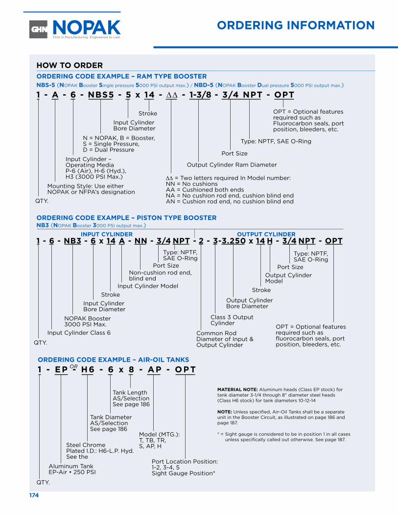
ORdeRIng InFORmATIOn hOw TO SeleCT The mOST eFFICIenT BOOSTeR
ORdeRIng COde exAmPle – RAm TyPe BOOSTeRnBS-5 (nOPAK Booster Single pressure 5000 PSI output max.) / nBd-5 (nOPAK Booster dual pressure 5000 PSI output max.)
1 - A - 6 - nBS5 - 5 x 14 - ∆∆ - 1-3/8 - 3/4 nPT - OPT
ORdeRIng COde exAmPle – PISTOn TyPe BOOSTeRnB3 (nOPAK Booster 3000 PSI output max.)
InPuT CylIndeR OuTPuT CylIndeR1 - 6 - nB3 - 6 x 14 A - nn - 3/4 nPT - 2 - 3-3.250 x 14 h - 3/4 nPT - OPT
hOw TO ORdeR
QTY.
QTY.
Input Cylinder – Operating Media P-6 (Air), H-6 (Hyd.), H3 (3000 PSI Max.)
Input Cylinder Class 6
Class 3 Output Cylinder
Output Cylinder Bore Diameter
Stroke
Mounting Style: Use either NOPAK or NFPA’s designation
N = NOPAK, B = Booster, S = Single Pressure, D = Dual Pressure
NOPAK Booster 3000 PSI Max.
Input Cylinder Bore Diameter
Input Cylinder Bore Diameter
Common Rod Diameter of Input & Output Cylinder
Input Cylinder Model
Output Cylinder Model
Port SizePort Size
Stroke
Stroke
∆∆ = Two letters required In Model number: NN = No cushions AA = Cushioned both ends NA = No cushion rod end, cushion blind end AN = Cushion rod end, no cushion blind end
Non-cushion rod end, blind end
Type: NPTF, SAE O-Ring
Type: NPTF, SAE O-Ring
Type: NPTF, SAE O-Ring
Port Size
Output Cylinder Ram Diameter
OPT = Optional features required such as Fluorocarbon seals, port position, bleeders, etc.
OPT = Optional features required such as fluorocarbon seals, port position, bleeders, etc.
ORdeRIng COde exAmPle – AIR-OIl TAnkS1 - eP - h6 - 6 x 8 - AP - OPT
QTY.
Steel Chrome Plated I.D.: H6-L.P. Hyd. See the
Aluminum Tank EP-Air • 250 PSI
Tank Diameter AS/Selection See page 186
Tank Length AS/SelectionSee page 186
Model (MTG.): T, TB, TR, S, AP, H
Port Location Position: 1-2, 3-4, 5 Sight Gauge Position*
OR
mATeRIAl nOTe: Aluminum heads (Class EP stock) for tank diameter 3-1/4 through 8" diameter steel heads (Class H6 stock) for tank diameters 10-12-14
nOTe: Unless specified, Air-Oil Tanks shall be a separate unit in the Booster Circuit, as illustrated on page 186 and page 187.
* = Sight gauge is considered to be in position 1 in all cases unless specifically called out otherwise. See page 187.
175www.nopak.com Boosters/tanks
STeP 1. SeleCTIng A SIngle PReSSuRe BOOSTeRPreliminary information needed:
A Thrust force or load required from work cylinder for application.
B Bore diameter of work cylinder and stroke length required to do the job (select a force greater than that required as a margin of safety).
C Input PSI pressure of work cylinder needed to obtain force selected.
d Available input PSI pressure to operate booster.
e Booster ratio.
exAmPle:Your application requires a thrust or force of 4,400 lbs. for 4" length.
From Class 3 Section Table C “Thrust Force and Displacement” you read 4,909 lbs. for a 2-1/2" diameter cylinder which requires an input pressure of 1,000 PSI to obtain this force. This allows a 500# force margin of safety.
Your available input pressure at site is 80 PSI shop air. Booster ratio can now be determined.
ratio = output pressure
= 1,000
= 12.5 input pressure 80
You have now established that: A Work cylinder force = 4,900 lbs.B Work cylinder diameter = 2-1/2" bore
Work cylinder stroke = 4" lengthC Booster output pressure = 1,000 PSI d Available input pressure = 80 PSI shop air e Booster ratio = 12.5
STeP 2. SeleCT BOOSTeR BORe And RAm SIzeUsing ratio from above Item E, select from Booster Selection Chart, page 184, the bore and ram size that reads closest to ratio. If exact ratio is not shown, then select next larger ratio. Next check if input PSI corresponds to application availability Item D above.
Read down input PSI column to output PSI that is equal or greater than Item C above. If table output is larger than needed then the ratio can be recalculated.
Now with your recalculated ratio, input pressure and closest output pressure, you can now read the booster bore diameter and ram size needed.
STeP 3. deTeRmIne BOOSTeR STROke Calculate the booster stroke using formula
S = V + VcL
Ra
S = Booster stroke V = Volume cubic inch of 2-1/2" bore work cylinder
times 4" stroke or 19.6 cu. in.VcL = Volume cubic inch plus oil volume cu. in. in circuit
lines (20 cu. in. FOR THIS EXAMPLE) TIMES 1% PER 1,000 PSI OR .01
Ra = Area of 1-3/8" diameter ram or 1.485 sq. in. nOTe: Substitute Pa (piston area) for Ra (ram area) in the above formula
when calculating a piston type booster or accumulator.
S = 19.6 + (19.6 + 20).01
1.485
S = 19.996
= 13.46 or 14" stroke 1.485
nOTe: To account for leakage (hydraulic slip) or any other uncertainties, a factor of safety of 20% should be added.
S = 14" x 1.20 = 16.8 OR 17" STROKE
From the following determining selection you would then order:
A 5" diameter single pressure NBS-5 booster with a 17" stroke using a 1-3/8 diameter ram. With an input pressure of 80 PSI air to be intensified to 1,058 PSI for full 4" stroke of 2-1/2" bore work cylinder with a recalculated ratio of 13.22.
SeleCTIng A duAl PReSSuRe BOOSTeR Steps No. 1 and 2 are the same as a single pressure booster. Proceed with step No. 3.
STeP 3. deTeRmIne BOOSTeR STROkeCalculate the booster stroke using formula.
S = V + VcL
+ 2 inch stroke required to close H.P. Seal
Ra
nOTe: For larger boosters with 3" diameter rod and over, use 3" plus calculated booster stroke.
S = Booster stroke
V = Volume cubic inch of 2-1/2" bore work cylinder times H.P. stroke length or 4.9 sq. in. x 1" = 4.9 cu. in. of H.P. stroke
VcL = Volume cu. in. plus oil volume cu. in. in circuit lines or 20 cu. in. times 1% per 1,000 PSI or .01
Ra = Area of 1-3/8" diameter ram or 1.485 sq. in. nOTe: Substitute Pa (piston area) for Ra (ram area) in the above formula
when calculating a piston type booster or accumulator.
S = 4.9 + (19.6 + 20).01
+ 2 1.485
S = 5.30
+ 2 1.485
S = 5.56 or 6" Booster stroke
S = 6 X 1.20 = 7.2 or 8" stroke (see note above).
From the following determining selection you would then order: A 5" diameter dual pressure NBD-5 booster with an 8" stroke using a 1-3/8" diameter ram. With an input pressure of 80 PSI air to be intensified to 1,058 PSI for last 1" stroke of 2-1/2" bore work cylinder with recalculated ratio of 13.22.
hOw TO SeleCT The mOST eFFICIenT BOOSTeR
176
nBS-5 SIngle PReSSuRe RAm TyPe BOOSTeR
PortsAir
Air
Optional High Pressure Oil
High Pressure Oil
This type booster has a single ram seal so the entire stroke is of intensified high pressure.
Low pressure air is directed to the booster input cylinder port to the cylinder chamber. Making contact with the larger surface of the retracted piston forces the piston with ram, forward, to begin the cylinder stroke. Low pressure oil is intensified in the nozzle chamber by the ram end force created by the larger air piston pushing. The high pressure oil is forced out of the nozzle port into the work cylinder for a high pressure continuous stroke. Oil flows out and back in through the nozzle port or can be piped in through the optional port located in the nozzle head. Makeup oil is provided from an external replenishing valve. The booster ratio of input and output pressure rated values are charted on page 184.
Booster Series NBS is similar to the dual pressure Series NBD except the center head which contains the port and seal for low pressure oil has been eliminated. Therefore, the primary purpose of this design is to provide high pressure oil to the work cylinder during its entire stroke.
Since the booster is neither self-filling or self-venting, provisions should be made to perform these operations in the external circuit.
See Booster Selection Chart, page 184 and “How To Select The Most Efficient Booster” on page 175.
nBS-5OuTPuT PReSSuRe uP TO 5000 PSI
Shop Air
Air-Oil Tank
P EXOPT
AIR
OIL
B AAir Booster
Replenish Valve
High Pressure Oil
Work Cylinder
Air
TyPICAl SIngle PReSSuRe CIRCuIT
nBS-5 SIngle PReSSuRe RAm TyPe BOOSTeR
177www.nopak.com Boosters/tanks
nBd-5 duAl PReSSuRe RAm TyPe BOOSTeR
Ports
Air
Air
Optional High Pressure Oil
Low Pressure Oil
High Pressure Oil
The dual pressure booster is used where the work cylinder is required to travel a short distance at high pressure after a substantial low pressure advance stroke. Because the booster ram operates only during the high pressure portion of the work stroke, a shorter booster stroke is required. In the fully retracted position, the ram is withdrawn from the high pressure ram seal allowing low pressure “approach stroke” oil to pass through to the work cylinder. This design makes the booster both self-filling and self-bleeding.
See Booster Selection Chart, page 184 and “How To Select The Most Efficient Booster” on page 175.
Low pressure air is directed to the Booster input cylinder port into the cylinder chamber. Making contact with the large surface of the retracted piston forces the piston with ram forward to start the cylinder stroke.
Air
Low Pressure Oil
Low Pressure Oil
Low pressure oil is flowing through the low pressure port into and through the high pressure bearing I.D. and seal. It continues through the nozzle chamber and out the port to the work cylinder. The ram is traveling under the same pressure as the input air. The low pressure oil reaching the work cylinder forces the rod forward which is called “the approach stroke.”
Air
High Pressure Oil
High Pressure Oil
The booster ram traveling forward now enters the high pressure bearing and seal cutting off the low pressure oil supply. The ram end force created by the large air piston now greatly intensifies the oil pressure contained in the nozzle chamber and is pushed out of the high pressure port to the work cylinder. This short stroke of the work cylinder is called the “high pressure stroke” of the work cycle. The booster ratio of input and output pressure rated values are charted on page 184. The input cylinder segment of NBD-5 boosters can be operated either with air or low pressure hydraulics. See the pressure limitations shown on page 184.
nBd-5OuTPuT PReSSuRe uP TO 5000 PSI
TyPICAl duAl PReSSuRe CIRCuITShop Air
Return Tank
Approach Tank
Low Pressure Oil
High Pressure Oil Optional Port
High Pressure Oil
PP EXEXOPTOPT
AIR
AIROIL
OIL
B A
Air
Air
Booster
Leveling Valve
Work Cylinder
nBd-5 duAl PReSSuRe RAm TyPe BOOSTeR
178
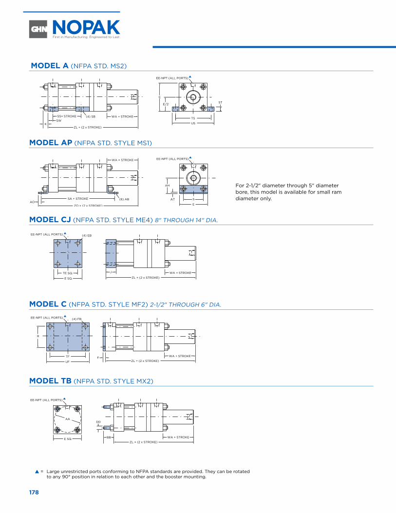
mOdel A (NFPA STD. MS2)
TS
US
E
E/2 ST
SS+ STROKE WA + STROKE
ZL + (2 x STROKE)
(4) SB
KSW
S
E
AH
AT
ZO + (2 x STROKE)
(6) ABAO
SA + STROKE
WA + STROKE
EE-NPT (ALL PORTS)
EE-NPT (ALL PORTS)
WA + STROKE
ZL + (2 x STROKE)F
WA + STROKE
ZL + (2 x STROKE)
DD
BB
EE-NPT (ALL PORTS)
E SQ.
AA
R
WA + STROKE
ZL + (2 x STROKE)
J
EE-NPT (ALL PORTS)
EE-NPT (ALL PORTS) (4) FB
(4) EB
E SQ.
TE SQ.
UF
TF
mOdel AP (NFPA STD. STYLE MS1)
TS
US
E
E/2 ST
SS+ STROKE WA + STROKE
ZL + (2 x STROKE)
(4) SB
KSW
S
E
AH
AT
ZO + (2 x STROKE)
(6) ABAO
SA + STROKE
WA + STROKE
EE-NPT (ALL PORTS)
EE-NPT (ALL PORTS)
WA + STROKE
ZL + (2 x STROKE)F
WA + STROKE
ZL + (2 x STROKE)
DD
BB
EE-NPT (ALL PORTS)
E SQ.
AA
R
WA + STROKE
ZL + (2 x STROKE)
J
EE-NPT (ALL PORTS)
EE-NPT (ALL PORTS) (4) FB
(4) EB
E SQ.
TE SQ.
UF
TF
mOdel CJ (NFPA STD. STYLE ME4) 8" THROUGH 14" DIA.
TS
US
E
E/2 ST
SS+ STROKE WA + STROKE
ZL + (2 x STROKE)
(4) SB
KSW
S
E
AH
AT
ZO + (2 x STROKE)
(6) ABAO
SA + STROKE
WA + STROKE
EE-NPT (ALL PORTS)
EE-NPT (ALL PORTS)
WA + STROKE
ZL + (2 x STROKE)F
WA + STROKE
ZL + (2 x STROKE)
DD
BB
EE-NPT (ALL PORTS)
E SQ.
AA
R
WA + STROKE
ZL + (2 x STROKE)
J
EE-NPT (ALL PORTS)
EE-NPT (ALL PORTS) (4) FB
(4) EB
E SQ.
TE SQ.
UF
TF
mOdel C (NFPA STD. STYLE MF2) 2-1/2" THROUGH 6" DIA.
TS
US
E
E/2 ST
SS+ STROKE WA + STROKE
ZL + (2 x STROKE)
(4) SB
KSW
S
E
AH
AT
ZO + (2 x STROKE)
(6) ABAO
SA + STROKE
WA + STROKE
EE-NPT (ALL PORTS)
EE-NPT (ALL PORTS)
WA + STROKE
ZL + (2 x STROKE)F
WA + STROKE
ZL + (2 x STROKE)
DD
BB
EE-NPT (ALL PORTS)
E SQ.
AA
R
WA + STROKE
ZL + (2 x STROKE)
J
EE-NPT (ALL PORTS)
EE-NPT (ALL PORTS) (4) FB
(4) EB
E SQ.
TE SQ.
UF
TF
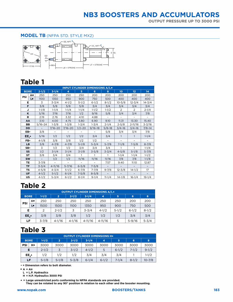
mOdel TB (NFPA STD. STYLE MX2)
TS
US
E
E/2 ST
SS+ STROKE WA + STROKE
ZL + (2 x STROKE)
(4) SB
KSW
S
E
AH
AT
ZO + (2 x STROKE)
(6) ABAO
SA + STROKE
WA + STROKE
EE-NPT (ALL PORTS)
EE-NPT (ALL PORTS)
WA + STROKE
ZL + (2 x STROKE)F
WA + STROKE
ZL + (2 x STROKE)
DD
BB
EE-NPT (ALL PORTS)
E SQ.
AA
R
WA + STROKE
ZL + (2 x STROKE)
J
EE-NPT (ALL PORTS)
EE-NPT (ALL PORTS) (4) FB
(4) EB
E SQ.
TE SQ.
UF
TF
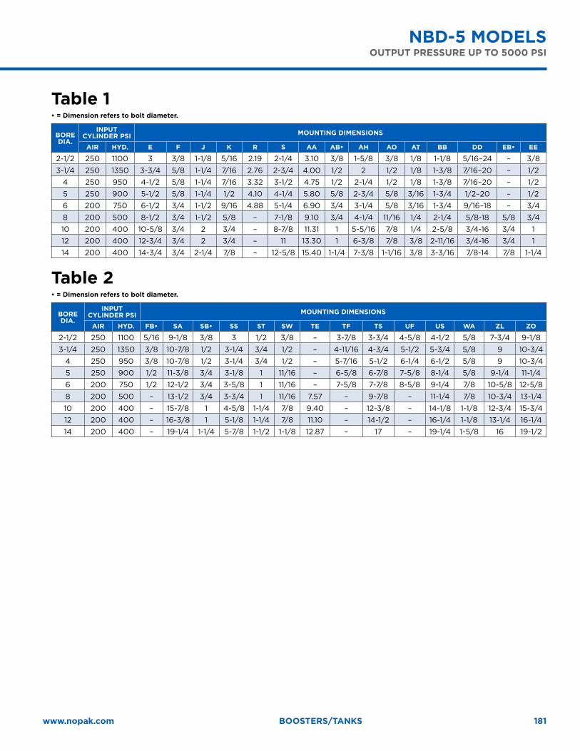
nBS-5 mOdelS
� = Large unrestricted ports conforming to NFPA standards are provided. They can be rotated to any 90° position in relation to each other and the booster mounting.
For 2-1/2" diameter through 5" diameter bore, this model is available for small ram diameter only.

179www.nopak.com Boosters/tanks
Table 1• = Dimension refers to bolt diameter.
BORe dIA.
InPuT CylIndeR PSI mOunTIng dImenSIOnS
AIR hyd. e F k R S AA AB• Ah AO AT BB dd EB• ee
2-1/2 250 1100 3 3/8 5/16 2.19 2-1/4 3.10 3/8 1-5/8 3/8 1/8 1-1/8 5/16–24 – 3/8
3-1/4 250 1350 3-3/4 5/8 7/16 2.76 2-3/4 4.00 1/2 2 1/2 1/8 1-3/8 7/16–20 – 1/2
4 250 950 4-1/2 5/8 7/16 3.32 3-1/2 4.75 1/2 2-1/4 1/2 1/8 1-3/8 7/16–20 – 1/2
5 250 900 5-1/2 5/8 1/2 4.10 4-1/4 5.80 5/8 2-3/4 5/8 3/16 1-3/4 1/2–20 – 1/2
6 200 750 6-1/2 3/4 9/16 4.88 5-1/4 6.90 3/4 3-1/4 5/8 3/16 1-3/4 9/16–18 – 3/4
8 200 500 8-1/2 3/4 5/8 – 7-1/8 9.10 3/4 4-1/4 11/16 1/4 2-1/4 5/8-18 5/8 3/4
10 200 400 10-5/8 3/4 3/4 – 8-7/8 11.31 1 5-5/16 7/8 1/4 2-5/8 3/4-16 3/4 1
12 200 400 12-3/4 3/4 3/4 – 11 13.30 1 6-3/8 7/8 3/8 2-11/16 3/4-16 3/4 1
14 200 400 14-3/4 3/4 7/8 – 12-5/8 15.40 1-1/4 7-3/8 1-1/16 3/8 3-3/16 7/8-14 7/8 1-1/4
Table 2• = Dimension refers to bolt diameter.
BORe dIA.
InPuT CylIndeR PSI mOunTIng dImenSIOnS
AIR hyd. FB• SA SB• SS ST Te TF TS uF uS wA zl zO
2-1/2 250 1100 5/16 7-5/8 3/8 3 1/2 – 3-7/8 3-3/4 4-5/8 4-1/2 5/8 6-1/4 7-1/4
3-1/4 250 1350 3/8 9-1/8 1/2 3-1/4 3/4 – 4-11/16 4-3/4 5-1/2 5-3/4 5/8 7-1/4 9
4 250 950 3/8 9-1/8 1/2 3-1/4 3/4 – 5-7/16 5-1/2 6-1/4 6-1/2 5/8 7-1/4 9
5 250 900 1/2 9-5/8 3/4 3-1/8 1 – 6-5/8 6-7/8 7-5/8 8-1/4 5/8 7-1/2 9-1/2
6 200 750 1/2 10-1/2 3/4 3-5/8 1 – 7-5/8 7-7/8 8-5/8 9-1/4 7/8 8-5/8 10-5/8
8 200 500 – 11-1/2 3/4 3-3/4 1 7.57 – 9-7/8 – 11-1/4 7/8 8-3/4 11-1/4
10 200 400 – 13-5/8 1 4-5/8 1-1/4 9.40 – 12-3/8 – 14-1/8 1-1/8 10-1/2 13-1/2
12 200 400 – 14-1/8 1 5-1/8 1-1/4 11.10 – 14-1/2 – 16-1/4 1-1/8 11 14
14 200 400 – 16-1/2 1-1/4 5-7/8 1-1/2 12.87 – 17 – 19-1/4 1-5/8 13-1/4 16-3/4
nBS-5 mOdelSOuTPuT PReSSuRe uP TO 5000 PSI
180
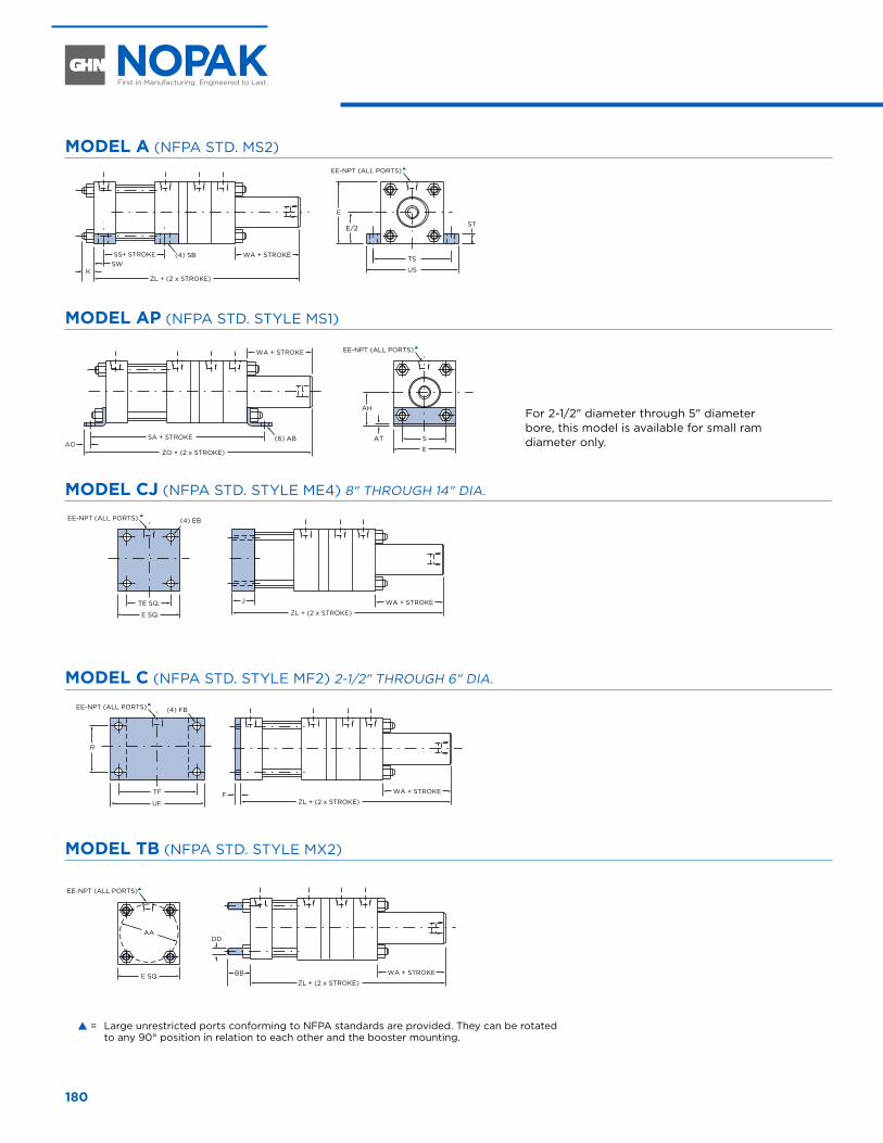
mOdel A (NFPA STD. MS2)
TS
US
E
E/2 ST
SS+ STROKE WA + STROKE
ZL + (2 x STROKE)
(4) SB
KSW
S
E
AH
AT
ZO + (2 x STROKE)
(6) ABAO
SA + STROKE
WA + STROKE
EE-NPT (ALL PORTS)
EE-NPT (ALL PORTS)
R
WA + STROKE
ZL + (2 x STROKE)F
J WA + STROKE
ZL + (2 x STROKE)
WA + STROKE
ZL + (2 x STROKE)
DD
BB
EE-NPT (ALL PORTS)
EE-NPT (ALL PORTS)
EE-NPT (ALL PORTS) (4) FB
(4) EB
E SQ.
E SQ.
TE SQ.
UF
TF
AA
mOdel AP (NFPA STD. STYLE MS1)
TS
US
E
E/2 ST
SS+ STROKE WA + STROKE
ZL + (2 x STROKE)
(4) SB
KSW
S
E
AH
AT
ZO + (2 x STROKE)
(6) ABAO
SA + STROKE
WA + STROKE
EE-NPT (ALL PORTS)
EE-NPT (ALL PORTS)
R
WA + STROKE
ZL + (2 x STROKE)F
J WA + STROKE
ZL + (2 x STROKE)
WA + STROKE
ZL + (2 x STROKE)
DD
BB
EE-NPT (ALL PORTS)
EE-NPT (ALL PORTS)
EE-NPT (ALL PORTS) (4) FB
(4) EB
E SQ.
E SQ.
TE SQ.
UF
TF
AA
mOdel CJ (NFPA STD. STYLE ME4) 8" THROUGH 14" DIA.
TS
US
E
E/2 ST
SS+ STROKE WA + STROKE
ZL + (2 x STROKE)
(4) SB
KSW
S
E
AH
AT
ZO + (2 x STROKE)
(6) ABAO
SA + STROKE
WA + STROKE
EE-NPT (ALL PORTS)
EE-NPT (ALL PORTS)
R
WA + STROKE
ZL + (2 x STROKE)F
J WA + STROKE
ZL + (2 x STROKE)
WA + STROKE
ZL + (2 x STROKE)
DD
BB
EE-NPT (ALL PORTS)
EE-NPT (ALL PORTS)
EE-NPT (ALL PORTS) (4) FB
(4) EB
E SQ.
E SQ.
TE SQ.
UF
TF
AA
mOdel C (NFPA STD. STYLE MF2) 2-1/2" THROUGH 6" DIA.
TS
US
E
E/2 ST
SS+ STROKE WA + STROKE
ZL + (2 x STROKE)
(4) SB
KSW
S
E
AH
AT
ZO + (2 x STROKE)
(6) ABAO
SA + STROKE
WA + STROKE
EE-NPT (ALL PORTS)
EE-NPT (ALL PORTS)
R
WA + STROKE
ZL + (2 x STROKE)F
J WA + STROKE
ZL + (2 x STROKE)
WA + STROKE
ZL + (2 x STROKE)
DD
BB
EE-NPT (ALL PORTS)
EE-NPT (ALL PORTS)
EE-NPT (ALL PORTS) (4) FB
(4) EB
E SQ.
E SQ.
TE SQ.
UF
TF
AA
mOdel TB (NFPA STD. STYLE MX2)
TS
US
E
E/2 ST
SS+ STROKE WA + STROKE
ZL + (2 x STROKE)
(4) SB
KSW
S
E
AH
AT
ZO + (2 x STROKE)
(6) ABAO
SA + STROKE
WA + STROKE
EE-NPT (ALL PORTS)
EE-NPT (ALL PORTS)
R
WA + STROKE
ZL + (2 x STROKE)F
J WA + STROKE
ZL + (2 x STROKE)
WA + STROKE
ZL + (2 x STROKE)
DD
BB
EE-NPT (ALL PORTS)
EE-NPT (ALL PORTS)
EE-NPT (ALL PORTS) (4) FB
(4) EB
E SQ.
E SQ.
TE SQ.
UF
TF
AA
nBd-5 mOdelS
� = Large unrestricted ports conforming to NFPA standards are provided. They can be rotated to any 90° position in relation to each other and the booster mounting.
For 2-1/2" diameter through 5" diameter bore, this model is available for small ram diameter only.
181www.nopak.com Boosters/tanks
Table 1• = Dimension refers to bolt diameter.
BORe dIA.
InPuT CylIndeR PSI mOunTIng dImenSIOnS
AIR hyd. e F J k R S AA AB• Ah AO AT BB dd EB• ee
2-1/2 250 1100 3 3/8 1-1/8 5/16 2.19 2-1/4 3.10 3/8 1-5/8 3/8 1/8 1-1/8 5/16–24 – 3/8
3-1/4 250 1350 3-3/4 5/8 1-1/4 7/16 2.76 2-3/4 4.00 1/2 2 1/2 1/8 1-3/8 7/16–20 – 1/2
4 250 950 4-1/2 5/8 1-1/4 7/16 3.32 3-1/2 4.75 1/2 2-1/4 1/2 1/8 1-3/8 7/16–20 – 1/2
5 250 900 5-1/2 5/8 1-1/4 1/2 4.10 4-1/4 5.80 5/8 2-3/4 5/8 3/16 1-3/4 1/2–20 – 1/2
6 200 750 6-1/2 3/4 1-1/2 9/16 4.88 5-1/4 6.90 3/4 3-1/4 5/8 3/16 1-3/4 9/16–18 – 3/4
8 200 500 8-1/2 3/4 1-1/2 5/8 – 7-1/8 9.10 3/4 4-1/4 11/16 1/4 2-1/4 5/8-18 5/8 3/4
10 200 400 10-5/8 3/4 2 3/4 – 8-7/8 11.31 1 5-5/16 7/8 1/4 2-5/8 3/4-16 3/4 1
12 200 400 12-3/4 3/4 2 3/4 – 11 13.30 1 6-3/8 7/8 3/8 2-11/16 3/4-16 3/4 1
14 200 400 14-3/4 3/4 2-1/4 7/8 – 12-5/8 15.40 1-1/4 7-3/8 1-1/16 3/8 3-3/16 7/8-14 7/8 1-1/4
Table 2• = Dimension refers to bolt diameter.
BORe dIA.
InPuT CylIndeR PSI mOunTIng dImenSIOnS
AIR hyd. FB• SA SB• SS ST Sw Te TF TS uF uS wA zl zO
2-1/2 250 1100 5/16 9-1/8 3/8 3 1/2 3/8 – 3-7/8 3-3/4 4-5/8 4-1/2 5/8 7-3/4 9-1/8
3-1/4 250 1350 3/8 10-7/8 1/2 3-1/4 3/4 1/2 – 4-11/16 4-3/4 5-1/2 5-3/4 5/8 9 10-3/4
4 250 950 3/8 10-7/8 1/2 3-1/4 3/4 1/2 – 5-7/16 5-1/2 6-1/4 6-1/2 5/8 9 10-3/4
5 250 900 1/2 11-3/8 3/4 3-1/8 1 11/16 – 6-5/8 6-7/8 7-5/8 8-1/4 5/8 9-1/4 11-1/4
6 200 750 1/2 12-1/2 3/4 3-5/8 1 11/16 – 7-5/8 7-7/8 8-5/8 9-1/4 7/8 10-5/8 12-5/8
8 200 500 – 13-1/2 3/4 3-3/4 1 11/16 7.57 – 9-7/8 – 11-1/4 7/8 10-3/4 13-1/4
10 200 400 – 15-7/8 1 4-5/8 1-1/4 7/8 9.40 – 12-3/8 – 14-1/8 1-1/8 12-3/4 15-3/4
12 200 400 – 16-3/8 1 5-1/8 1-1/4 7/8 11.10 – 14-1/2 – 16-1/4 1-1/8 13-1/4 16-1/4
14 200 400 – 19-1/4 1-1/4 5-7/8 1-1/2 1-1/8 12.87 – 17 – 19-1/4 1-5/8 16 19-1/2
nBd-5 mOdelSOuTPuT PReSSuRe uP TO 5000 PSI
182
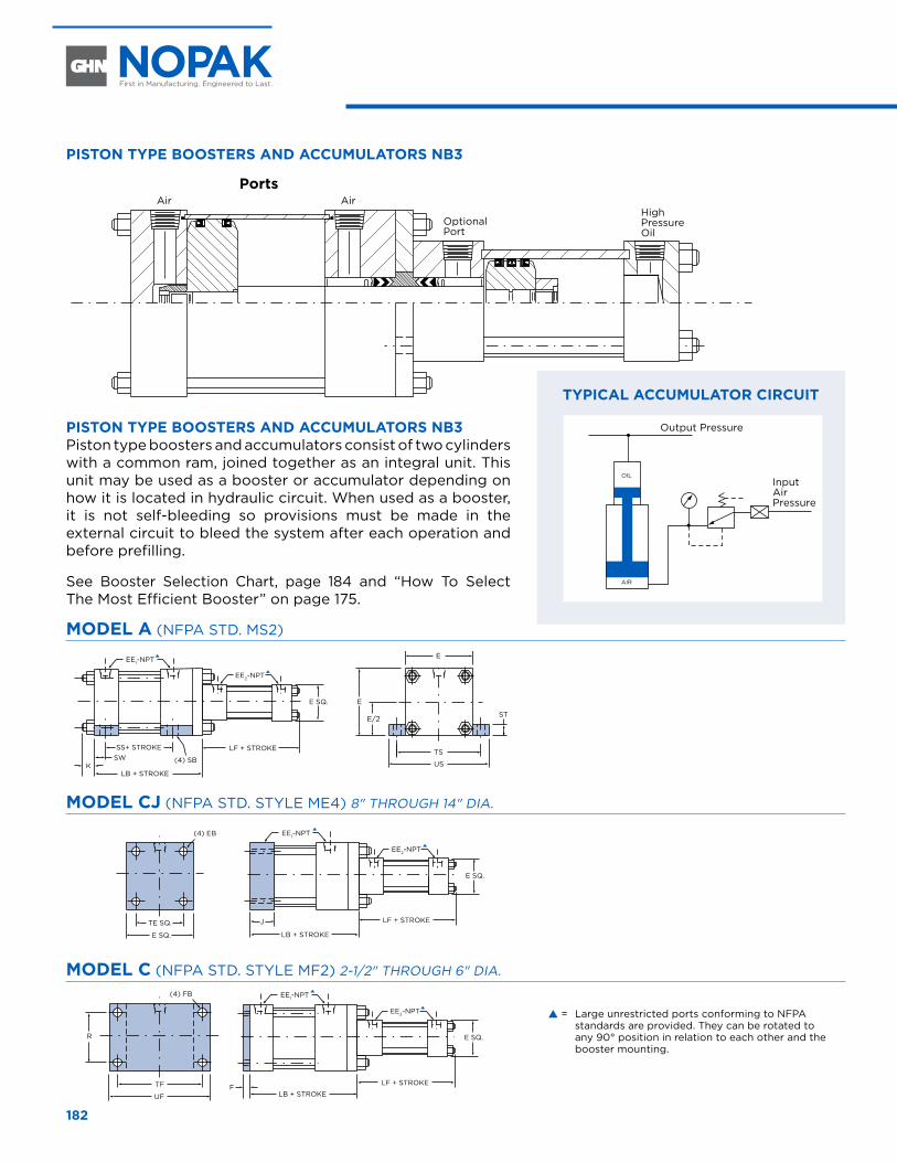
PISTOn TyPe BOOSTeRS And ACCumulATORS nB3
PortsAir Air
Optional Port
High Pressure Oil
PISTOn TyPe BOOSTeRS And ACCumulATORS nB3 Piston type boosters and accumulators consist of two cylinders with a common ram, joined together as an integral unit. This unit may be used as a booster or accumulator depending on how it is located in hydraulic circuit. When used as a booster, it is not self-bleeding so provisions must be made in the external circuit to bleed the system after each operation and before prefilling.
See Booster Selection Chart, page 184 and “How To Select The Most Efficient Booster” on page 175.
mOdel A (NFPA STD. MS2)
TS
US
E
E
E SQ.
E/2 ST
SS+ STROKE LF + STROKE
LB + STROKE
(4) SBK
SW
EE1-NPT
EE1-NPT
EE2-NPT
EE1-NPT
EE2-NPT
R
F
J
(4) FB
(4) EB
E SQ.
TE SQ.
UF
TF
EE1-NPT
EE2-NPT
LF + STROKE
EE2-NPT
E SQ.
E SQ.
E SQ.
LB + STROKE
DD
BB
LF + STROKE
LB + STROKE
LF + STROKE
LB + STROKE
E SQ.
AA
mOdel CJ (NFPA STD. STYLE ME4) 8" THROUGH 14" DIA.
TS
US
E
E
E SQ.
E/2 ST
SS+ STROKE LF + STROKE
LB + STROKE
(4) SBK
SW
EE1-NPT
EE1-NPT
EE2-NPT
EE1-NPT
EE2-NPT
R
F
J
(4) FB
(4) EB
E SQ.
TE SQ.
UF
TF
EE1-NPT
EE2-NPT
LF + STROKE
EE2-NPT
E SQ.
E SQ.
E SQ.
LB + STROKE
DD
BB
LF + STROKE
LB + STROKE
LF + STROKE
LB + STROKE
E SQ.
AA
mOdel C (NFPA STD. STYLE MF2) 2-1/2" THROUGH 6" DIA.
TS
US
E
E
E SQ.
E/2 ST
SS+ STROKE LF + STROKE
LB + STROKE
(4) SBK
SW
EE1-NPT
EE1-NPT
EE2-NPT
EE1-NPT
EE2-NPT
R
F
J
(4) FB
(4) EB
E SQ.
TE SQ.
UF
TF
EE1-NPT
EE2-NPT
LF + STROKE
EE2-NPT
E SQ.
E SQ.
E SQ.
LB + STROKE
DD
BB
LF + STROKE
LB + STROKE
LF + STROKE
LB + STROKE
E SQ.
AA
nB3 BOOSTeRS And ACCumulATORS
Output Pressure
Input Air Pressure
AIR
OIL
TyPICAl ACCumulATOR CIRCuIT
� = Large unrestricted ports conforming to NFPA standards are provided. They can be rotated to any 90° position in relation to each other and the booster mounting.
183www.nopak.com Boosters/tanks
mOdel TB (NFPA STD. STYLE MX2)
TS
US
E
E
E SQ.
E/2 ST
SS+ STROKE LF + STROKE
LB + STROKE
(4) SBK
SW
EE1-NPT
EE1-NPT
EE2-NPT
EE1-NPT
EE2-NPT
R
F
J
(4) FB
(4) EB
E SQ.
TE SQ.
UF
TF
EE1-NPT
EE2-NPT
LF + STROKE
EE2-NPT
E SQ.
E SQ.
E SQ.
LB + STROKE
DD
BB
LF + STROKE
LB + STROKE
LF + STROKE
LB + STROKE
E SQ.
AA
Table 1InPuT CylIndeR dImenSIOnS A/l �
BORe 2-1/2 3-1/4 4 5 6 8 10 12 14
PSIA� 250 250 250 250 200 200 200 200 200l� 1100 1350 950 900 750 500 400 400 400
e 3 3-3/4 4-1/2 5-1/2 6-1/2 8-1/2 10-5/8 12-3/4 14-3/4F 3/8 5/8 5/8 5/8 3/4 3/4 3/4 3/4 3/4J 1-1/8 1-1/4 1-1/4 1-1/4 1-1/2 1-1/2 2 2 2-1/4k 5/16 7/16 7/16 1/2 9/16 5/8 3/4 3/4 7/8R 2.19 2.76 3.32 4.10 4.88 – – – –
AA 3.10 4.00 4.75 5.80 6.90 9.10 11.31 13.30 15.40BB 5/16–24 1-3/8 1-3/8 1-3/4 1-3/4 2-1/4 2-5/8 2-11/16 3-3/16dd – 7/16–20 7/16–20 1/2–20 9/16–18 5/8–18 3/4–16 3/4–16 7/8–14EB• 3/8 – – – – 5/8 3/4 3/4 7/8
ee1� 5/16 1/2 1/2 1/2 3/4 3/4 1 1 1-1/4
FB• 4-1/8 3/8 3/8 1/2 1/2 – – – –lB 3/8 4-7/8 4-7/8 5-1/8 5-3/4 5-7/8 7-1/8 7-5/8 8-7/8SB• 3 1/2 1/2 3/4 3/4 3/4 1 1 1-1/4SS 1/2 3-1/4 3-1/4 3-1/8 3-5/8 3-3/4 4-5/8 5-1/8 5-7/8ST 3/8 3/4 3/4 1 1 1 1-1/4 1-1/4 1-1/2Sw – 1/2 1/2 11/16 11/16 11/16 7/8 7/8 1-1/8Te 3-7/8 – – – – 7.57 9.40 11.10 12.87TF 3-3/4 4-11/16 5-7/16 6-5/8 7-5/8 – – – –TS 4-5/8 4-3/4 5-1/2 6-7/8 7-7/8 9-7/8 12-3/8 14-1/2 17uF 4-1/2 5-1/2 6-1/4 7-5/8 8-5/8 – – – –uS 4-1/2 5-3/4 6-1/2 8-1/4 9-1/4 11-1/4 14-1/8 16-1/4 19-1/4
Table 2OuTPuT CylIndeR dImenSIOnS A/l �
BORe 1-1/2 2 2-1/2 3-1/4 4 5 6 8
PSIA� 250 250 250 250 250 250 200 200l� 1500 1500 1100 1350 950 900 750 500
e 2 2-1/2 3 3-3/4 4-1/2 5-1/2 6-1/2 8-1/2
ee2� 3/8 3/8 3/8 1/2 1/2 1/2 3/4 3/4
lF 3-7/8 4-1/16 4-1/16 4-11/16 4-11/16 5 5-9/16 5-3/4
Table 3 OuTPuT CylIndeR dImenSIOnS h�
BORe 1-1/2 2 2-1/2 3-1/4 4 5 6 8
PSI h� 3000 3000 3000 3000 3000 3000 3000 3000
e 2-1/2 3 3-1/2 4-1/2 5 6-1/2 7-1/2 9-1/2
ee2� 1/2 1/2 1/2 3/4 3/4 3/4 1 1-1/2
lF 5-1/8 5-1/8 5-3/8 6-1/4 6-1/2 7-1/4 8-1/2 10-7/8
• = Dimension refers to bolt diameter.� A = Air L = L.P. Hydraulics H = H.P. Hydraulics 3000 PSI� = Large unrestricted ports conforming to NFPA standards are provided.
They can be rotated to any 90° position in relation to each other and the booster mounting.
nB3 BOOSTeRS And ACCumulATORSOuTPuT PReSSuRe uP TO 3000 PSI
184
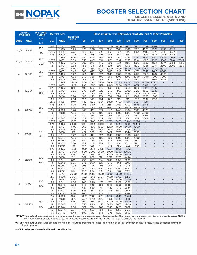
dRIVIng CylIndeR
PReSSuRe RATIng OuTPuT RAm
BOOSTeR RATIo•
InTenSIFIed OuTPuT hydRAulIC PReSSuRe (PSI) AT InPuT PReSSuRe
BORe AReAAIR
hyd.
dIA. AReA 60 80 100 200 250 400 500 750 900 950 1100 1350
2–1/2 4.909250
1100
0.625 0.307 16.00 960 1280 1600 3200 4000 6401 8001 12001 14401 15201 17601 –1 0.785 6.25 375 500 625 1250 1563 2500 3125 4688 5625 5938 6876 –
1.375 1.485 3.31 198 264 331 661 827 1322 1653 2480 2975 3141 3637 –1.75 2.405 2.04 122 163 204 408 510 816 1020 1531 1837 1939 2245 –
3–1/4 8.296250
1350
1 0.785 10.56 634 845 1056 2113 2641 4225 5282 7922 9507 10035 11619 142601.375 1.485 5.59 335 447 559 1117 1397 2235 2794 4190 5028 5308 6146 75431.75 2.405 3.45 207 276 345 690 862 1380 1725 2587 3104 3277 3794 46562 3.142 2.64 158 211 264 528 660 1056 1320 1981 2377 2509 2905 3565
4 12.566250
950
1 0.785 16.00 960 1280 1600 3200 4000 6400 8000 12000 14400 15200 – –1.375 1.485 8.46 508 677 846 1693 2116 3385 4231 6347 7617 8040 – –1.75 2.405 5.22 313 418 522 1045 1306 2090 2612 3918 4702 4963 – –2 3.142 4.00 240 320 400 800 1000 1600 2000 3000 3600 3800 – –
2.5 4.909 2.56 154 205 256 512 640 1024 1280 1920 2304 2432 – –
5 19.634250
900
1 0.785 25.00 1500 2000 2500 5000 6250 10000 12500 18750 22500 – – –1.375 1.485 13.22 793 1058 1322 2645 3306 5289 6611 9917 11901 – – –1.75 2.405 8.16 490 653 816 1633 2041 3265 4082 6122 7347 – – –2 3.142 6.25 375 500 625 1250 1562 2500 3125 4687 5625 – – –
2.5 4.909 4.00 240 320 400 800 1000 1600 2000 3000 3600 – – –3 7.068 2.78 167 222 278 556 694 1111 1389 2083 2500 – – –
3.5 9.621 2.04 122 163 204 408 510 816 1020 1531 1837 – – –
6 28.274200
750
1.375 1.485 19.04 1142 1523 1904 3808 4760 7617 9521 14281 – – – –1.75 2.405 11.76 705 940 1176 2351 2939 4702 5878 8816 – – – –2 3.142 9.00 540 720 900 1800 2250 3600 4500 6750 – – – –
2.5 4.909 5.76 346 461 576 1152 1440 2304 2880 4320 – – – –3 7.068 4.00 240 320 400 800 1000 1600 2000 3000 – – – –
3.5 9.621 2.94 176 235 294 588 735 1176 1469 2204 – – – –4 12.566 2.25 135 180 225 450 563 900 1125 1688 – – – –
8 50.264200
500
1.375 1.485 33.85 2031 2708 3385 6770 8463 13540 16926 – – – – –1.75 2.405 20.90 1254 1672 2090 4180 5224 8359 10449 – – – – –2 3.142 16.00 960 1280 1600 3200 4000 6400 8000 – – – – –
2.5 4.909 10.24 614 819 1024 2048 2560 4096 5120 – – – – –3 7.068 7.11 427 569 711 1422 1778 2844 3556 – – – – –
3.5 9.621 5.22 313 418 522 1045 1306 2090 2612 – – – – –4 12.566 4.00 240 320 400 800 1000 1600 2000 – – – – –
4.5 15.904 3.16 190 253 316 632 790 1264 1580 – – – – –5 19.634 2.56 154 205 256 512 640 1024 1280 – – – – –
5.5 23.758 2.12 127 169 212 423 529 846 1058 – – – – –
10 78.538200
400
1.75 2.405 32.65 1959 2612 3265 6531 8163 13061 – – – – – –2 3.142 25.00 1500 2000 2500 5000 6250 10000 – – – – – –
2.5 4.909 16.00 960 1280 1600 3200 4000 6400 – – – – – –3 7.068 11.11 667 889 1111 2222 2778 4444 – – – – – –
3.5 9.621 8.16 490 653 816 1633 2041 3265 – – – – – –4 12.566 6.25 375 500 625 1250 1563 2500 – – – – – –
4.5 15.904 4.94 296 395 494 988 1235 1975 – – – – – –5 19.634 4.00 240 320 400 800 1000 1600 – – – – – –
5.5 23.758 3.31 198 264 331 661 826 1322 – – – – – –
12 113.094200
400
2 3.142 36.00 2160 2880 3600 7200 9000 14400 – – – – – –2.5 4.909 23.04 1382 1843 2304 4608 5760 9216 – – – – – –3 7.068 16.00 960 1280 1600 3200 4000 6400 – – – – – –
3.5 9.621 11.76 705 940 1176 2351 2939 4702 – – – – – –4 12.566 9.00 540 720 900 1800 2250 3600 – – – – – –
4.5 15.904 7.11 427 569 711 1422 1778 2844 – – – – – –5 19.634 5.76 346 461 576 1152 1440 2304 – – – – – –
5.5 23.758 4.76 286 381 476 952 1190 1904 – – – – – –
14 153.934200
400
2.5 4.909 31.36 1882 2509 3136 6272 7840 12544 – – – – – –3 7.068 21.78 1307 1742 2178 4356 5444 8711 – – – – – –
3.5 9.621 16.00 960 1280 1600 3200 4000 6400 – – – – – –4 12.566 12.25 735 980 1225 2450 3063 4900 – – – – – –
4.5 15.904 9.68 581 774 968 1936 2420 3872 – – – – – –5 19.634 7.84 470 627 784 1568 1960 3136 – – – – – –
5.5 23.758 6.48 389 518 648 1296 1620 2592 – – – – – –nOTe: When output pressures are in the gray shaded area, the output pressure has exceeded the rating for the output cylinder and then Boosters NBS-5
THROUGH NBD-5 should not be used. For output pressures greater than 5000 PSI, please consult the factory.
nOTe: When output pressures are not shown, either output pressure has exceeded rating of output cylinder or input pressure has exceeded rating of input cylinder.
• = CL3 series not shown in this ratio combination.
BOOSTeR SeleCTIOn ChARTSIngle PReSSuRe nBS-5 And
duAl PReSSuRe nBd-5 (5000 PSI)
BOOSTeR SeleCTIOn ChART SIngle PReSSuRe nBS-5 And duAl PReSSuRe nBd-5 (5000 PSI)
BOOSTeR SeleCTIOn ChARTnB-3 (3000 PSI)
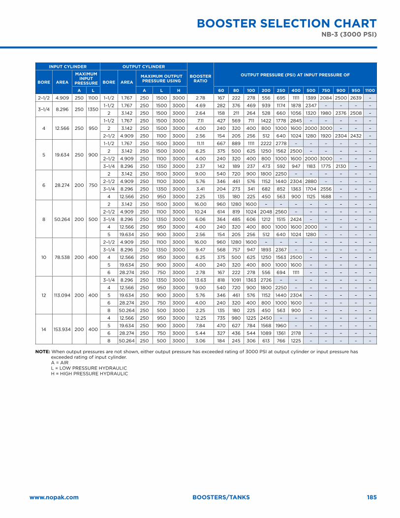
185www.nopak.com Boosters/tanks
InPuT CylIndeR OuTPuT CylIndeR
BOOSTeR RATIO
OuTPuT PReSSuRe (PSI) AT InPuT PReSSuRe OF
BORe AReA
mAxImum InPuT
PReSSuRe BORe AReAmAxImum OuTPuT PReSSuRe uSIng
A l A l h 60 80 100 200 250 400 500 750 900 950 1100
2–1/2 4.909 250 1100 1–1/2 1.767 250 1500 3000 2.78 167 222 278 556 695 1111 1389 2084 2500 2639 –
3–1/4 8.296 250 13501–1/2 1.767 250 1500 3000 4.69 282 376 469 939 1174 1878 2347 – – – –
2 3.142 250 1500 3000 2.64 158 211 264 528 660 1056 1320 1980 2376 2508 –
4 12.566 250 950
1–1/2 1.767 250 1500 3000 7.11 427 569 711 1422 1778 2845 – – – – –
2 3.142 250 1500 3000 4.00 240 320 400 800 1000 1600 2000 3000 – – –
2–1/2 4.909 250 1100 3000 2.56 154 205 256 512 640 1024 1280 1920 2304 2432 –
5 19.634 250 900
1–1/2 1.767 250 1500 3000 11.11 667 889 1111 2222 2778 – – – – – –
2 3.142 250 1500 3000 6.25 375 500 625 1250 1562 2500 – – – – –
2–1/2 4.909 250 1100 3000 4.00 240 320 400 800 1000 1600 2000 3000 – – –
3–1/4 8.296 250 1350 3000 2.37 142 189 237 473 592 947 1183 1775 2130 – –
6 28.274 200 750
2 3.142 250 1500 3000 9.00 540 720 900 1800 2250 – – – – – –
2–1/2 4.909 250 1100 3000 5.76 346 461 576 1152 1440 2304 2880 – – – –
3–1/4 8.296 250 1350 3000 3.41 204 273 341 682 852 1363 1704 2556 – – –
4 12.566 250 950 3000 2.25 135 180 225 450 563 900 1125 1688 – – –
8 50.264 200 500
2 3.142 250 1500 3000 16.00 960 1280 1600 – – – – – – – –
2–1/2 4.909 250 1100 3000 10.24 614 819 1024 2048 2560 – – – – – –
3–1/4 8.296 250 1350 3000 6.06 364 485 606 1212 1515 2424 – – – – –
4 12.566 250 950 3000 4.00 240 320 400 800 1000 1600 2000 – – – –
5 19.634 250 900 3000 2.56 154 205 256 512 640 1024 1280 – – – –
10 78.538 200 400
2–1/2 4.909 250 1100 3000 16.00 960 1280 1600 – – – – – – – –
3–1/4 8.296 250 1350 3000 9.47 568 757 947 1893 2367 – – – – – –
4 12.566 250 950 3000 6.25 375 500 625 1250 1563 2500 – – – – –
5 19.634 250 900 3000 4.00 240 320 400 800 1000 1600 – – – – –
6 28.274 250 750 3000 2.78 167 222 278 556 694 1111 – – – – –
12 113.094 200 400
3–1/4 8.296 250 1350 3000 13.63 818 1091 1363 2726 – – – – – – –
4 12.566 250 950 3000 9.00 540 720 900 1800 2250 – – – – – –
5 19.634 250 900 3000 5.76 346 461 576 1152 1440 2304 – – – – –
6 28.274 250 750 3000 4.00 240 320 400 800 1000 1600 – – – – –
8 50.264 250 500 3000 2.25 135 180 225 450 563 900 – – – – –
14 153.934 200 400
4 12.566 250 950 3000 12.25 735 980 1225 2450 – – – – – – –
5 19.634 250 900 3000 7.84 470 627 784 1568 1960 – – – – – –
6 28.274 250 750 3000 5.44 327 436 544 1089 1361 2178 – – – – –
8 50.264 250 500 3000 3.06 184 245 306 613 766 1225 – – – – –
nOTe: When output pressures are not shown, either output pressure has exceeded rating of 3000 PSI at output cylinder or input pressure has exceeded rating of input cylinder. A = AIR L = LOW PRESSURE HYDRAULIC H = HIGH PRESSURE HYDRAULIC
BOOSTeR SeleCTIOn ChARTnB-3 (3000 PSI) BOOSTeR SeleCTIOn ChART
nB-3 (3000 PSI)
186
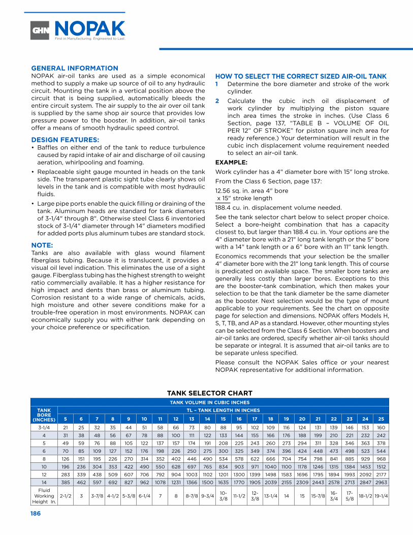
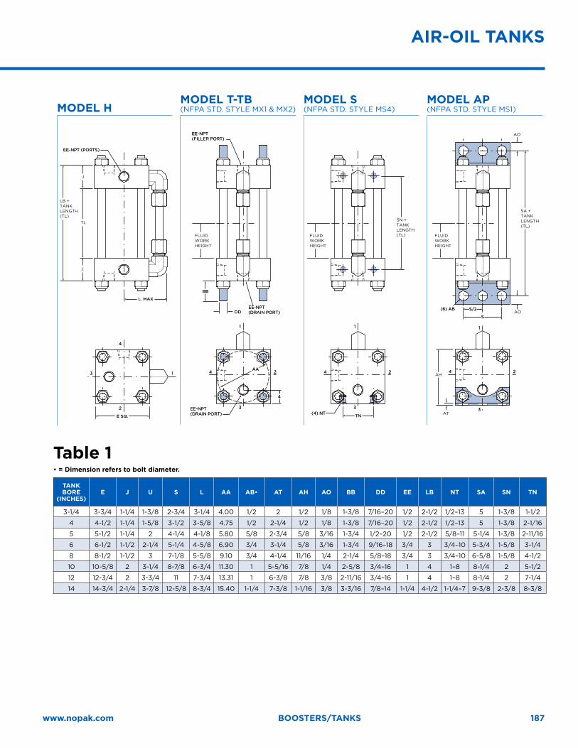
geneRAl InFORmATIOn NOPAK air-oil tanks are used as a simple economical method to supply a make up source of oil to any hydraulic circuit. Mounting the tank in a vertical position above the circuit that is being supplied, automatically bleeds the entire circuit system. The air supply to the air over oil tank is supplied by the same shop air source that provides low pressure power to the booster. In addition, air-oil tanks offer a means of smooth hydraulic speed control.
deSIgn FeATuReS: • Baffles on either end of the tank to reduce turbulence
caused by rapid intake of air and discharge of oil causing aeration, whirlpooling and foaming.
• Replaceable sight gauge mounted in heads on the tank side. The transparent plastic sight tube clearly shows oil levels in the tank and is compatible with most hydraulic fluids.
• Large pipe ports enable the quick filling or draining of the tank. Aluminum heads are standard for tank diameters of 3-1/4" through 8". Otherwise steel Class 6 inventoried stock of 3-1/4" diameter through 14" diameters modified for added ports plus aluminum tubes are standard stock.
nOTe: Tanks are also available with glass wound filament fiberglass tubing. Because it is translucent, it provides a visual oil level indication. This eliminates the use of a sight gauge. Fiberglass tubing has the highest strength to weight ratio commercially available. It has a higher resistance for high impact and dents than brass or aluminum tubing. Corrosion resistant to a wide range of chemicals, acids, high moisture and other severe conditions make for a trouble-free operation in most environments. NOPAK can economically supply you with either tank depending on your choice preference or specification.
hOw TO SeleCT The CORReCT SIzed AIR-OIl TAnk1 Determine the bore diameter and stroke of the work
cylinder.
2 Calculate the cubic inch oil displacement of work cylinder by multiplying the piston square inch area times the stroke in inches. (Use Class 6 Section, page 137, “TABLE B – VOLUME OF OIL PER 12” OF STROKE” for piston square inch area for ready reference.) Your determination will result in the cubic inch displacement volume requirement needed to select an air-oil tank.
exAmPle: Work cylinder has a 4" diameter bore with 15" long stroke.
From the Class 6 Section, page 137:
12.56 sq. in. area 4" bore x 15" stroke length
188.4 cu. in. displacement volume needed.
See the tank selector chart below to select proper choice. Select a bore-height combination that has a capacity closest to, but larger than 188.4 cu. in. Your options are the 4" diameter bore with a 21" long tank length or the 5" bore with a 14" tank length or a 6" bore with an 11" tank length.
Economics recommends that your selection be the smaller 4" diameter bore with the 21" long tank length. This of course is predicated on available space. The smaller bore tanks are generally less costly than larger bores. Exceptions to this are the booster-tank combination, which then makes your selection to be that the tank diameter be the same diameter as the booster. Next selection would be the type of mount applicable to your requirements. See the chart on opposite page for selection and dimensions. NOPAK offers Models H, S, T, TB, and AP as a standard. However, other mounting styles can be selected from the Class 6 Section. When boosters and air-oil tanks are ordered, specify whether air-oil tanks should be separate or integral. It is assumed that air-oil tanks are to be separate unless specified.
Please consult the NOPAK Sales office or your nearest NOPAK representative for additional information.
AIR-OIl TAnkSAIR-OIl TAnkS
TAnk SeleCTOR ChARTTAnk VOlume In CuBIC InCheS
TAnk BORe
(InCheS)
Tl – TAnk lengTh In InCheS
5 6 7 8 9 10 11 12 13 14 15 16 17 18 19 20 21 22 23 24 25
3-1/4 21 25 32 35 44 51 58 66 73 80 88 95 102 109 116 124 131 139 146 153 160
4 31 38 48 56 67 78 88 100 111 122 133 144 155 166 176 188 199 210 221 232 242
5 49 59 76 88 105 122 137 157 174 191 208 225 243 260 273 294 311 328 346 363 378
6 70 85 109 127 152 176 198 226 250 275 300 325 349 374 396 424 448 473 498 523 544
8 126 151 195 226 270 314 352 402 446 490 534 578 622 666 704 754 798 841 885 929 968
10 196 236 304 353 422 490 550 628 697 765 834 903 971 1040 1100 1178 1246 1315 1384 1453 1512
12 283 339 438 509 607 706 792 904 1003 1102 1201 1300 1399 1498 1583 1696 1795 1894 1993 2092 2177
14 385 462 597 692 827 962 1078 1231 1366 1500 1635 1770 1905 2039 2155 2309 2443 2578 2713 2847 2963
Fluid Working
Height In.2-1/2 3 3-7/8 4-1/2 5-3/8 6-1/4 7 8 8-7/8 9-3/4 10-
3/8 11-1/2 12-3/8 13-1/4 14 15 15-7/8 16-
3/417-5/8 18-1/2 19-1/4
187www.nopak.com Boosters/tanks
mOdel hmOdel T-TB (NFPA STD. STYLE MX1 & MX2)
mOdel S (NFPA STD. STYLE MS4)
mOdel AP (NFPA STD. STYLE MS1)
EE-NPT (PORTS)EE-NPT (PORTS)
EE-NPT(FILLER PORT)EE-NPT(FILLER PORT)
EE-NPT(DRAIN PORT)EE-NPT(DRAIN PORT)
(6) AB(6) AB
(4) NT(4) NT
44 22
11
33
L. MAXL. MAX
DDDDS/2S/2
SS
BBBB
TNTN
44 22
11
33
44 22
11
33
AAAAAH
AT
FLUIDWORKHEIGHT
AO
AO
SA +TANKLENGTH (TL)
SN +TANKLENGTH (TL)
LB +TANKLENGTH (TL)
TL
J
J
44
EE-NPT(DRAIN PORT)EE-NPT(DRAIN PORT)E SQ.E SQ.
44
22
1133
FLUIDWORKHEIGHT
FLUIDWORKHEIGHT
Table 1• = Dimension refers to bolt diameter.
TAnk BORe
(InCheS)e J u S l AA AB• AT Ah AO BB dd ee lB nT SA Sn Tn
3-1/4 3-3/4 1-1/4 1-3/8 2-3/4 3-1/4 4.00 1/2 2 1/2 1/8 1-3/8 7/16–20 1/2 2-1/2 1/2–13 5 1-3/8 1-1/2
4 4-1/2 1-1/4 1-5/8 3-1/2 3-5/8 4.75 1/2 2-1/4 1/2 1/8 1-3/8 7/16–20 1/2 2-1/2 1/2–13 5 1-3/8 2-1/16
5 5-1/2 1-1/4 2 4-1/4 4-1/8 5.80 5/8 2-3/4 5/8 3/16 1-3/4 1/2–20 1/2 2-1/2 5/8–11 5-1/4 1-3/8 2-11/16
6 6-1/2 1-1/2 2-1/4 5-1/4 4-5/8 6.90 3/4 3-1/4 5/8 3/16 1-3/4 9/16–18 3/4 3 3/4–10 5-3/4 1-5/8 3-1/4
8 8-1/2 1-1/2 3 7-1/8 5-5/8 9.10 3/4 4-1/4 11/16 1/4 2-1/4 5/8–18 3/4 3 3/4–10 6-5/8 1-5/8 4-1/2
10 10-5/8 2 3-1/4 8-7/8 6-3/4 11.30 1 5-5/16 7/8 1/4 2-5/8 3/4–16 1 4 1–8 8-1/4 2 5-1/2
12 12-3/4 2 3-3/4 11 7-3/4 13.31 1 6-3/8 7/8 3/8 2-11/16 3/4–16 1 4 1–8 8-1/4 2 7-1/4
14 14-3/4 2-1/4 3-7/8 12-5/8 8-3/4 15.40 1-1/4 7-3/8 1-1/16 3/8 3-3/16 7/8–14 1-1/4 4-1/2 1-1/4–7 9-3/8 2-3/8 8-3/8
AIR-OIl TAnkS

188