Embed Size (px)
Citation preview

BULLETIN 912-A
February 1999
HIGH PRESSURE BLOWER Model HPB Direct Drive/Belt Driven

Model HPB High Pressure Blowers
ContentsIntroduction . . . . . . . . . . . . . . . . . . . . . . . . . 2Design Features . . . . . . . . . . . . . . . . . . . . . . .3Drive Arrangements . . . . . . . . . . . . . . . . . . . .3Accessories . . . . . . . . . . . . . . . . . . . . . . . . . .4How To Select A Pressure Blower . . . . . . . . . .6Performance Data . . . . . . . . . . . . . . . . . . . . .7Material Specifications For Standard Units . . . .20Dimensional Data . . . . . . . . . . . . . . . . . . . . .21Typical Specifications . . . . . . . . . . . . . . . . . .25
©1999 Aerovent
Bulletin illustrations cover the general appearance of products at the time of publication andwe reserve the right to make changes in design and construction at any time without notice.
Aerovent’s High Pressure Blowers feature high staticpressure capabilities from 11" to 69" and air volume to6500 CFM. High Pressure Blowers are durable, compactand versatile fans used in applications such as:
● Agitation and aeration● Product cooling and drying● Conveying● Supplying combustion air to furnaces and ovens● Exhausting● Transporting solid materials ● Gas boosting and compressing
Landfill VentilationAerovent commonly utilizes Model HPB High PressureBlowers in landfill ventilation applications to extractmethane gas. Methane emitted from decomposed wastein landfill sites can contaminate the surrounding prop-erty, through migration, if not properly contained.Typically, a gas collection system collects the methanegenerated by the waste and uses it to produce electric-ity for onsite equipment operation or for resale to localutilities. Recovered methane gas provides a cleansource of fuel, improves air quality, and reduces green-house gas emissions.
To extract methane gas from the landfill, perforatedpipes (average 4" diameter) are sunk vertically downinto the landfill and back filled with gravel. The pipesare manifolded together at the surface, and connectedto the high pressure blower. Gas flows through thepressure blower and then to either a gas collection sys-tem or to a flare stack where it is burned off.
Typical Pressure BlowerConstruction for LandfillVentilation● Abrasive and corrosion resistant coating on all air-
stream parts (for example, 3055 plasite baked phe-nolic).
● Thrust vanes on the back of the wheel — to ensurenegative pressure where the shaft penetrates thehousing.
● AMCA “B” Spark Resistant Construction — for thehazardous methane atmosphere. ● Stuffing Box Shaft Seal — to
obtain the best seal against gasleakage, although it does notmake the unit completely gastight. Available only in Ar-rangement 1 or Arrangement8.
● Continuous double-weldedscroll.
● Explosion Proof Motor (ClassI, Group D, Division 1).
Material ConveyingHigh Pressure Blowers can alsobe utilized to convey material forindustrial processes. An examplewould be polystyrene, or “Styro-foam,” for the manufacture of
plastic grocery bags. Styrofoam is difficult to transportby hand because it is light and bulky. A high pressureblower is utilized to pneumatically convey this materialfrom storage containers to the extrusion process formelting, molding and cooling. The polystyrene materialis then melted on an extruder ring and air is blownthrough the ring to form a plastic tube. In many casesa separate high pressure blower is utilized to blow airthrough the ring. After the tube is formed, one end isheat sealed to complete the forming of the plastic bag.
2 Aerovent Bulletin 912

Aerovent Bulletin 912 3
Design Features
Drive Arrangements
ConstructionA continuously-welded heavy-gauge steel housing andmotor base provide for rugged, heavy-duty service.Rotatable and reversible housings are offered as a stan-dard for all sizes.
An inlet venturi with a guard is standard for all units.A flanged or pipe inlet is available as an option. Thestandard discharge is an all-welded heavy-duty flangedrilled to match American Standard Class 125 bolt pat-tern.
WheelThe Model HPB Blower is furnishedwith an aluminum alloy wheel,and is provided with a split-taperlock bushing for easy wheelremoval from the shaft. Standardfor wheel sizes 14" through 26" isriveted construction, while size27" through 30" wheels are weld-ed. Welded steel wheels are avail-
Arr. 4Inlet Side
Arr. 4Drive Side
Arrangement 1Arrangement 1 has a shaft and bearing assemblydesigned for the motor to be mounted in one of thefour AMCA standard motor positions, W, X, Y or Z.
Standard Unit Arrangement 4Wheel is mounted directly to motor shaft, providingmaximum performance at minimum cost and mainte-nance. Available for the full range of wheel sizes from14" through 30". Maximum temperature is 180°F.
able in all sizes for heat applications (temperatures300°F to 600°F).
For increased fan capacity, a wider wheel is offeredfor sizes 22" through 26". These fans are identified as“W” (wide) and the ratings are listed on pages 19 and20.
Heat FansArrangement 1 and 8 fans areavailable with optional construc-tion for operation at temperaturesup to 600°F. High temperaturemodifications include a weldedsteel wheel, special base con-struction to accommodate a heatslinger and guard, and aluminumpaint finish. Fans requiring “W”(wide) wheels are not availablewith 600°F construction.
Heat Slinger
Arrangement 8Direct coupled unit with an extended pedestal toaccommodate a motor and flexible coupling. Fanassembly can remain intact while removing motor forservice. Available for the full range of wheel sizes from14" through 30". Maximum temperature with aluminumwheel is 300°F.
Arrangement 9Built to Arrangement 1 specifications, but with anadjustable motor slide base and V-belt drive mountedon the fan pedestal. Motor located on right side as stan-dard. Available throughout the range of sizes, and canbe modified for operation at elevated temperatures.Pedestal dimensions limit selection to small motorsonly. Consult factory for availability of belt drivenArrangement 9 fans.
neg
Arr. 8

4 Aerovent Bulletin 912
Accessories
Shaft SealFour types of frictionshaft seals are available:
1. Elastomeric RotarySeal — Rides against aheavy Teflon wearplate. Spare seal pro-vided as standard. Cutoff old seal and pushspare into place. Thisseal is suitable foroperation up to 300°F.
2. Ceramic Felt — Elements are encased betweenhousing drive side and metal retaining plate. Ceramicfelt inserts may be easily split for field installationand maintenance. The seal is best suited for 301°F to600°F operation. These seals minimize leakagearound the shaft opening but are not gas-tight.
3. Lubricated Seals — For longer seal life. Suitable to300°F.
4. Stuffing Boxes — Constructed of three rows of per-manently lubricated packing material encasedbetween the housing drive side and the machinedmetal packing gland. This shaft seal provides the bestseal against gas leakage but is not totally gas-tight.Suitable for temperatures to 500°F. Specify tempera-ture for proper packing material.
Wheel Thrust VanesProvide a simple solution to applications which requirenegative pressure at the point of shaft penetration of thescroll in order to prevent the escape of undesirablefumes or gases.
Outlet DampersControl airflow on discharge side of blower. Dampershave manual lever control. Recommended where a pipeis not connected to the discharge side of the blower.Standard damper is suitable for temperatures to 400°F.
Available in Arr. 8 or inBelt Driven Fans Only
Inlet Filters(Weatherhood Shown)Permanent oil-wetted filters or throwaway cellulose fil-ters are recommended where heavy dust conditionsexist. An all-weather hood option is available. Pressuredrop through clean filter, less hood, is 0.25" W.G.Specify flanged inlet for mounting. A combination fil-ter/silencer is also available (see page 5).
Flexible SleeveConnects fan to standard piping and reduces noise andvibration transmission. Furnished with stainless steelhose clamps.
Tube AdaptorBolts to flanged inlet or discharge of fan. Provides con-nection to American Standard pipe sizes or a flexiblesleeve (see above).
Aerovent Bulletin 912 5
Accessories
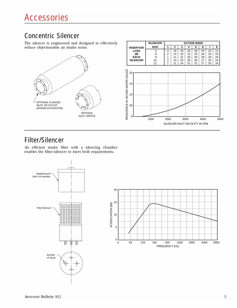
SILENCER OCTAVE BAND
INSERTION SIZE 1 2 3 4 5 6 7 8LOSS 4 4 18 26 33 36 29 23 21
dB 6 2 14 23 31 33 28 25 23EACH 8 1 11 21 29 30 28 26 25
SILENCER 10 2 14 23 30 30 27 25 2412 1 11 24 31 31 27 25 24
Concentric SilencerThe silencer is engineered and designed to effectivelyreduce objectionable air intake noise.
Filter/Silencer An efficient intake filter with a silencing chamberenables the filter/silencer to meet both requirements.
OPTIONAL FLANGEDINLET OR OUTLET(SHOWN IN PHANTOM)
OPTIONALINLET ORIFICE
1000 2000 3000 4000 5000
SILENCER INLET VELOCITY IN FPM
.20
.15
.10
.05
0
RE
SIS
TAN
CE
IN IN
CH
ES
WAT
ER
GA
UG
E
0 63 125 250 500 1000 2000 4000 8000FREQUENCY (HZ)
20
15
10
5
0
ATTE
NTU
ATIO
N (d
B)
WeatherhoodWith Lift Handles
Filter Element
Number of Studs

6 Aerovent Bulletin 912
How To Select A Pressure BlowerTo select a high pressure blower from the fan perfor-mance curves on pages 7 through 20, the system designCFM and SP are needed (at standard density of 0.075lb./ft3).
For high pressure blowers, it is recommended toselect a motor 1 to 2 sizes larger than the performancecurves suggest, as described in the following example:
Example 1:Given a performance of 400 CFM at 25" SP, select a size19" High Pressure Blower with a 4" diameter outlet.The performance looks as follows (also shown on page9 of this catalog):
The operating point of 400 CFM and 25" SP is notedabove by the diamond shape.
Therefore, the performance point of 400 CFM at 25"SP requires a 5 HP motor.
NOTE: For a 5% or 1" reduction in design static pres-sure, the performance will require a 71⁄2 HP motor, asshown by the triangle shape. It is common in systemdesign to put a 5 to 10% safety factor on the system sta-tic pressure. However, when utilizing this type of fan, itis important to consider its increasing brake horsepow-er characteristic.
The performance curve for the Size 19", 4" outletduct High Pressure Blower shown below depicts theincreasing brake horsepower characteristic more clear-ly. For a small reduction in static pressure, the brakehorsepower increases.
Suction Pressure CorrectionsFor Inlet Suction ConditionsA suction pressure correction is necessary for inlet stat-ic pressures (usually 10" or greater). The static pressureis negative on the inlet or suction side of the fan so apartial vacuum is created at the fan inlet. This partialvacuum lowers the density of the air (or gas) or makesthe air (or gas) rarefied. Therefore, the air must be con-verted to standard conditions by using the “SuctionPressure Correction Factor,” as shown in the examplebelow.
Example 2:Given a fan inlet static pressure of 20" at 70°F at sealevel, the suction pressure correction ratio is calculatedusing the following formula:
Ratio = Ambient Absolute Press. – Fan Inlet SPAmbient Absolute Press.
= 407 – Fan Inlet SP407
Ambient Absolute Press. = 407"
For this example:
Ratio = 407 – 20 = 0.9509407
Using this ratio, the static pressure at standard condi-tions is calculated as follows:
SP @ Std. Cond. = 20" = 21.03" SP @ Std. Cond.0.9509
The static pressure of 21.03" is used for selecting the fanfrom the performance curves.
5 HP
71⁄2 HP
300 500400 600 700
26
25
23
22
24
CFM
Sta
tic P
ress
ure
(Inc
hes
W.G
.)
400 CFM at 25"SP, 3.91 BHP
With a 5% safety factor in static pressure,actual design may be 24" SP, which wouldrequire 5.38 BHP and a 71⁄2 HP motor.
Decreasein SP
SP @ 3500 RPM SP2 =24" SP
400 CFM, SP1 = 25"
Increasein BHP
BHP2 =5.38
BHP1 =3.91
BHP @ 3500 R
PM
33
30
27
24
21
18
15
12
3
0 4 8 12 16 20
6
9
CFM IN 100s
STA
TIC
PR
ES
SU
RE
13.20
12.00
10.80
9.60
8.40
7.20
6.00
4.80
3.60
2.40
1.20
BR
AK
E H
OR
SE
PO
WE
R

Aerovent Bulletin 912 7
Performance Data
The Aerovent Model HPB Blowers shown on pages 7through 20 of this bulletin have been tested and ratedin accordance with industry accepted test codes, andare guaranteed by Aerovent to deliver rated perfor-mance.
Performances shown are based on 3500 RPM motorspeeds and standard inlet air density of 0.075 lbs./ft3.
Range of performance is within motor horsepowerspecified.
Catalog Numbering System
Performance shown is for installation Type D: Ducted inlet, ducted outlet.Performance ratings do not include the effects of appurtenances in the airstream
STA
TIC
PR
ES
SU
RE
– I
NC
HE
S W
.G.
W 26 - 12 - HPB - 3500 - 60
Wide HousingNominal Fan Size (In.)Nominal Outlet Size (In.)Fan TypeRPMMotor Horsepower

8 Aerovent Bulletin 912
Performance shown is for installation Type D: Ducted inlet, ducted outlet.Performance ratings do not include the effects of appurtenances in the airstream

Aerovent Bulletin 912 9
Performance shown is for installation Type D: Ducted inlet, ducted outlet.Performance ratings do not include the effects of appurtenances in the airstream

10 Aerovent Bulletin 912
Performance shown is for installation Type D: Ducted inlet, ducted outlet.Performance ratings do not include the effects of appurtenances in the airstream

Aerovent Bulletin 912 11
Performance shown is for installation Type D: Ducted inlet, ducted outlet.Performance ratings do not include the effects of appurtenances in the airstream

12 Aerovent Bulletin 912
Performance shown is for installation Type D: Ducted inlet, ducted outlet.Performance ratings do not include the effects of appurtenances in the airstream

Aerovent Bulletin 912 13
Performance shown is for installation Type D: Ducted inlet, ducted outlet.Performance ratings do not include the effects of appurtenances in the airstream

14 Aerovent Bulletin 912
Performance shown is for installation Type D: Ducted inlet, ducted outlet.Performance ratings do not include the effects of appurtenances in the airstream

Aerovent Bulletin 912 15
SIZE 27" — 12" 27" Wheel Dia. – 12" Outlet 3500 RPM
CFM
SIZE 27" — 10" 27" Wheel Dia. – 10" Outlet 3500 RPM
CFM
SIZE 27" — 8" 27" Wheel Dia. – 8" Outlet 3500 RPM
CFM
Performance shown is for installation Type D: Ducted inlet, ducted outlet.Performance ratings do not include the effects of appurtenances in the airstream.
SIZE 27" — 6" 27" Wheel Dia. – 6" Outlet 3500 RPM
CFM
STA
TIC
PR
ES
SU
RE
– I
NC
HE
S W
.G.
30323436384042444648505254565860
0 500 1000 1500 2000 2500 3000 3500
15 hp 20 hp 25 hp 30 hp 40 hp
4042444648505254565860
0 500 1000 1500 2000 2500 3000 3500 4000
15 hp 25 hp 40 hp30 hp20 hp
50 hp
30323436384042444648505254565860
0 500 1000 1500 2000 2500 3000 3500 4000 4500 5000
15 hp 25 hp 40 hp30 hp20 hp
50 hp 60 hp
30323436384042444648505254565860
0 500 1000 1500 2000 2500 3000 3500 4000 4500 5000
15 hp 25 hp 40 hp30 hp20 hp 50 hp
60 hp

16 Aerovent Bulletin 912
Performance shown is for installation Type D: Ducted inlet, ducted outlet.Performance ratings do not include the effects of appurtenances in the airstream.
SIZE 28" — 6" 28" Wheel Dia. – 6" Outlet 3500 RPM
CFM
SIZE 28" — 8" 28" Wheel Dia. – 8" Outlet 3500 RPM
CFM
SIZE 28" — 10" 28" Wheel Dia. –10" Outlet 3500 RPM
CFM
SIZE 28" — 12" 28" Wheel Dia. – 12" Outlet 3500 RPM
CFM
STA
TIC
PR
ES
SU
RE
– I
NC
HE
S W
.G.
30323436384042444648505254565860
0 500 1000 1500 2000 2500 3000 3500 4000
15 hp 20 hp 25 hp 30 hp 40 hp 50 hp
3032343638404244464850525456586062
0 500 1000 1500 2000 2500 3000 3500 4000 4500 5000
15 hp 20 hp 25 hp 30 hp 40 hp 50 hp 60 hp 75 hp
32
34
36
38
40
42
44
46
48
50
52
54
56
58
60
0 500 1000 1500 2000 2500 3000 3500 4000 4500 5000
15 hp 20 hp 25 hp 30 hp 40 hp 50 hp 60 hp
75 hp
3032343638404244464850525456586062
0 500 1000 1500 2000 2500 3000 3500 4000 4500 5000
15 hp 20 hp 40 hp25 hp 30 hp 50 hp 60 hp

Aerovent Bulletin 912 17
Performance shown is for installation Type D: Ducted inlet, ducted outlet.Performance ratings do not include the effects of appurtenances in the airstream.
SIZE 29" — 6" 29" Wheel Dia. – 6" Outlet 3500 RPM
CFM
SIZE 29" — 8" 29" Wheel Dia. – 8" Outlet 3500 RPM
CFM
SIZE 29" — 10" 29" Wheel Dia. –10" Outlet 3500 RPM
CFM
SIZE 29" — 12" 29" Wheel Dia. – 12" Outlet 3500 RPM
CFM
2830323436384042444648505254565860626466
0 500 1000 1500 2000 2500 3000 3500 4000 4500
20 hp 25 hp 30 hp 40 hp 50 hp 60 hp
34
36
38
40
42
44
46
48
50
52
54
56
58
60
62
64
66
0 500 1000 1500 2000 2500 3000 3500 4000 4500 5000
20 hp 25 hp 30 hp 50 hp40 hp 60 hp 75 hp
34
36
38
40
42
44
46
48
50
52
54
56
58
60
62
64
66
0 500 1000 1500 2000 2500 3000 3500 4000 4500 5000 5500
20 hp 25 hp 50 hp30 hp 40 hp 75 hp60 hp
34
36
38
40
42
44
46
48
50
52
54
56
58
60
62
64
66
0 500 1000 1500 2000 2500 3000 3500 4000 4500 5000 5500
25 hp 40 hp 50 hp 60 hp20 hp 30 hp 75 hp
STA
TIC
PR
ES
SU
RE
– I
NC
HE
S W
.G.
18 Aerovent Bulletin 912
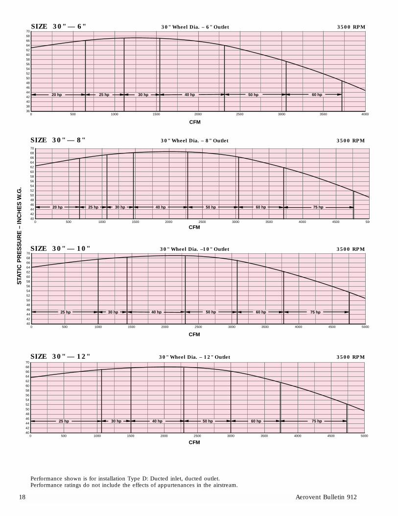
Performance shown is for installation Type D: Ducted inlet, ducted outlet.Performance ratings do not include the effects of appurtenances in the airstream.
SIZE 30" — 6" 30" Wheel Dia. – 6" Outlet 3500 RPM
CFM
SIZE 30" — 8" 30" Wheel Dia. – 8" Outlet 3500 RPM
CFM
SIZE 30" — 10" 30" Wheel Dia. –10" Outlet 3500 RPM
CFM
SIZE 30" — 12" 30" Wheel Dia. – 12" Outlet 3500 RPM
CFM
363840424446485052545658606264666870
0 500 1000 1500 2000 2500 3000 3500 4000
20 hp 40 hp 50 hp25 hp 30 hp 60 hp
40424446485052545658606264666870
0 500 1000 1500 2000 2500 3000 3500 4000 4500 500
30 hp 40 hp 50 hp 60 hp20 hp 25 hp 75 hp
40424446485052545658606264666870
0 500 1000 1500 2000 2500 3000 3500 4000 4500 5000
25 hp 30 hp 40 hp 50 hp 60 hp 75 hp
40424446485052545658606264666870
0 500 1000 1500 2000 2500 3000 3500 4000 4500 5000
25 hp 30 hp 50 hp 60 hp40 hp 75 hp
STA
TIC
PR
ES
SU
RE
– I
NC
HE
S W
.G.
Aerovent Bulletin 912 19
Performance shown is for installation Type D: Ducted inlet, ducted outlet.Performance ratings do not include the effects of appurtenances in the airstream.
STA
TIC
PR
ES
SU
RE
– I
NC
HE
S W
.G.

20 Aerovent Bulletin 912
HOUSING MOTOR BASE ALUMINUM WHEEL STEEL WHEEL
SIZE SIDESCROLL FRAME BASE
WEIGHT WR2 WEIGHT WR2 MIN.
PLATESBACK & REINFORCE- PLATE REINFORCE-
(LB) (LB-FT2) (LB) (LB-FT2)MOTOR
SIDES MENT MENT HP*14" 8.4 1.4 25.2 4.2 11⁄215" 8.9 1.7 26.7 5.1 316" 0.1350" 0.135" 0.25" x 2" 0.250" 0.25" x 2" 9.4 2.1 28.2 6.3 317" 10.5 2.6 31.5 7.8 518" 11.6 3.2 34.8 9.6 519" 11.6 3.1 34.8 9.3 521" 0.1350" 0.135" 0.25" x 2" 0.250" 0.25" x 2" 13.5 4.6 40.5 13.8 71⁄222" 14.4 5.5 43.2 16.5 1023" 14.0 6.0 42.0 18.0 1024" 15.2 6.9 45.6 20.7 1025"
0.1875" 0.135" 0.25" x 2" 0.250" 0.25" x 2"16.2 8.0 48.6 24.0 10
26" 17.8 9.2 53.4 27.6 1027" 34.6 18.5 104 55.6 2528" 36.6 21.1 110 63.3 3029"
0.1875" 0.135" 0.25" x 2" 0.250" 0.25" x 2"38.6 23.8 116 71.6 30
30" 40.6 26.8 122 80.4 40W21" 16.5 4.9 49.5 14.7 71⁄2W22" 17.6 5.7 52.8 17.1 10W23" 18.0 6.8 54.0 20.4 10W24"
0.1875" 0.135" 0.25" x 2" 0.250" 0.25" x 2"19.6 7.8 58.8 23.4 10
W25" 21.4 9.1 64.2 27.3 10W26" 22.4 10.3 67.2 30.9 15
Material Specifications for Standard Units
*To overcome inertia of steel wheel.
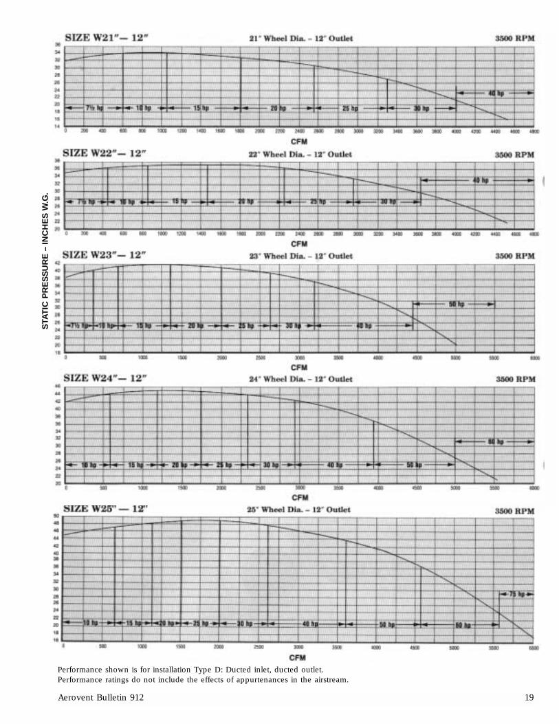
Performance shown is for installation Type D: Ducted inlet, ducted outlet.Performance ratings do not include the effects of appurtenances in the airstream.
STA
TIC
PR
ES
SU
RE
– I
NC
HE
S W
.G.

Aerovent Bulletin 912 21
Dimensional Data – Arrangement 1
F
G
C B
A
D
T
T
U U
KL
(I.D.)
E
SM
RN J
H
9/16 DIA.HOLES (4)
REQ'D.
WHL SHFTA
OUT. FLNGEC D E F G H J K L M N R S T U
SIZE DIA SIZE B14"15" 4"16" 11⁄2 183/8 6" 171⁄4 127/16 109/16 1013/16 133/16 1111/16 233⁄4 71⁄2 31⁄2 65⁄8 61⁄4 171⁄4 41⁄4 12 83⁄4 95⁄817" 8"18"
19"4"
21" 11⁄2 243/86" 173/4
165⁄8 143/4 141⁄2 175⁄8 155⁄8 233/4 61⁄2 4 65⁄8 61⁄4 171⁄4 43⁄8 12 11 117⁄822"
8"10" 213/4
23" 6"19
24"11⁄2 267/8
8"1811/16 1611/16 167/16 1913/16 179/16 231⁄2 61⁄2 5 8 53⁄4 17 41/32 12 123⁄8 131⁄4
25" 10"23
26" 12"27" 6"
261⁄228"
23/16 308"
225⁄8 1913/16 175⁄8 251⁄8 201⁄8 2915/16 61⁄2 6 8 53⁄4 211/16 41/16 16 133⁄8 141⁄429" 10"
281⁄230" 12"
W21"W22"W23"
115⁄16 267/8 12" 27 1811⁄16 1611⁄16 167⁄16 1913⁄16 179⁄16 253⁄8 77⁄16 6 8 75⁄8 1715⁄16 431⁄32 12 123⁄8 131⁄4W24"W25"W26"
HSG.SIZE
18"
22"
26"
30"
W26"

22 Aerovent Bulletin 912
Dimensional Data – Arrangement 4
F
C B
D
AG
E
L(I.D.)
N
H
M
J
Std. InletVenturi
U
U
T
T
S R
9/16" Dia. Holes
BASE DETAIL
NOTES:Flanged discharge is standard. Optional inlet flanges are available in any combination shown on page 24. Inlet flanges smaller than inlet venturi will require anoptional pipe inlet (performance will be affected). Inlet flange will match discharge flange where possible, if not otherwise specified. All flanges match AmericanStandard Class 125 drilling.
All dimensions in inches. *CONSULT FACTORY FOR DOWNBLAST DISCHARGE DIMENSIONS.
HOUSING WHEEL OUTLETSIZE SIZE SIZE
B C D E F G J L M N R S T U
14" 4", 6"15"
4"18" 16"
6"171⁄4 127⁄16 109⁄16 1013⁄16 133⁄16 1111⁄16 61⁄2 65⁄8 61⁄4 181⁄2 41⁄4 131⁄4 85⁄8 91⁄2
17"8"
18"19"
22" 21"173⁄4
165⁄8 143⁄4 141⁄2 175⁄8 155⁄8 61⁄2 65⁄8 61⁄4 205⁄8 43⁄8 151⁄4 11 117⁄822" 10" 213⁄423" 6"24" 8"
1926"
25" 10"1811⁄16 1611⁄16 167⁄16 1913⁄16 179⁄16 61⁄2 8 53⁄4 245⁄16 47⁄8 181⁄2 123⁄8 131⁄4
26" 12"23
27" 6"28" 8"
261⁄230"
29" 10"225⁄8 1913⁄16 175⁄8 251⁄8 201⁄8 61⁄2 8 53⁄4 245⁄16 47⁄8 181⁄2 133⁄8 141⁄4
30" 12"281⁄2
W21"W22"W23"
W26"W24"
12" 27 1811⁄16 1611⁄16 167⁄16 1913⁄16 179⁄16 77⁄16 8 75⁄8 251⁄4 513⁄16 181⁄2 123⁄8 131⁄4
W25"W26"
HOUSING MOTORH
SIZE FRAMEA OPEN ENCLOSED
MOTOR MOTOR143T & 145T 165⁄8182T & 184T 175⁄8
18"213T
25 25
215T183⁄8
143T & 145T 215⁄8182T & 184T 225⁄8
22" 213T & 215T 233⁄8 271⁄8 271⁄8254T256T
243⁄8
182T & 184T 251⁄8213T & 215T 257⁄8254T & 256T 267⁄8
26" 284TS 3013⁄16 3013⁄16
286TS275⁄8
324TS326TS
285⁄8
HOUSING MOTORH
SIZE FRAMEA OPEN ENCLOSED
MOTOR MOTOR254T & 256T 297⁄8
284TS & 286TS 305⁄830"
324TS & 326TS 315⁄83013⁄16 3013⁄16
364TS & 365TS 325⁄8213T & 215T 257⁄8254T & 256T 267⁄8
284TS286TS
275⁄8
W26" 324TS 3211⁄16 3211⁄16
326TS285⁄8
364TS365TS
295⁄8
4"6"8"

Aerovent Bulletin 912 23
Dimensional Data – Arrangement 8
HSG WHL SHFTA
OUT. FLNGEC D E F G J L M R T U
SIZE SIZE DIA SIZE B14"15" 4"
18" 16" 11⁄2 183/8 6" 171⁄4 127/16 109/16 1013/16 133/16 1111⁄16 61⁄2 65⁄8 61⁄4 41⁄4 83⁄4 95⁄817" 8"18"
19"4"
22" 21" 11⁄2 243/86" 173/4
165⁄8 143/4 141⁄2 175⁄8 155⁄8 61⁄2 65⁄8 61⁄4 43⁄8 11 117⁄822"
8"10" 213/4
23" 6"19
26"24"
11⁄2 267/88"
1811/16 1611/16 167/16 1913/16 179/16 61⁄2 8 53⁄4 41/32 123⁄8 131⁄425" 10"
2326" 12"27" 6"
261⁄230"
28"23/16 30
8"225⁄8 1913/16 175⁄8 251⁄8 201⁄8 61⁄2 8 53⁄4 41/16 133⁄8 141⁄4
29" 10"281⁄2
30" 12"W21"W22"
W26"W23"
115⁄16 267/8 12" 27 1811⁄16 1611⁄16 167⁄16 1913⁄16 179⁄16 77⁄16 8 75⁄8 431⁄32 123⁄8 131⁄4W24"W25"W26"
F
G
D
A
C B
T T
U U
E
MS S
RN
H
J
L(I.D.)
19/16 DIA.HOLES (6)
REQ'D.

24 Aerovent Bulletin 912
O.D.
B.C.
PipeSize
11/8"13/8"
JJ ±1/4"
FLANGED INLET PIPE INLET(OPTIONAL) (OPTIONAL)
FLANGE DIMENSIONSINLET/DISCHARGE BOLT HOLES
SIZEI.D. O.D.
CIRCLE NO. SIZE4" 4 9 71⁄2 8 3⁄46" 6 11 91⁄2 8 7⁄88" 8 131⁄2 113⁄4 8 7⁄8
10" 10 16 141⁄4 12 112" 12 19 17 12 1
DISCHARGEPOSITION
CLOCK-WISE
*
COUNTERCLOCK-
WISE
*
RO
TAT
ION
TOPHORIZONTAL
BOTTOMHORIZONTAL UPBLAST TOP
45° DOWNBOTTOM
45* UPTOP
45° UP
*SPECIAL CONSTRUCTION IS REQUIRED FOR CLOCKWISE AND COUNTERCLOCKWISE DOWNBLAST POSITIONS.
Discharge Arrangements
Standard Pipe Sizes Offered:65⁄8" O.D. on 18" and 22" housings85⁄8" O.D. on 26", 30" and W26" housings.
Others sizes available upon request.
Flange Dimensions

Aerovent Bulletin 912 25
Typical Specifications
Fans shall be Model HPB High Pressure Centrifugal Blowers as manufactured by Aerovent, Minneapolis, Minnesota,and shall be of the size and capacity as indicated in the fan schedule. Model HPB High Pressure Blowers shall betested and certified in accordance with ANSI/ASHRAE 51-1985 and ANSI/AMCA 210-85 test codes and guaranteed bythe manufacturer to deliver the rated, published performance levels. In addition, each unit shall be factory test runprior to shipment.
CONSTRUCTION — The Model HPB High Pressure Blower shall have a continuously welded heavy-gauge steelhousing and motor base for rugged, heavy duty service. All sizes shall have rotatable and reversible housing, inletventuri with a guard, and all-welded heavy duty flanged discharge drilled to match American Standard Class #125bolt pattern. A flanged or piped inlet is available as an option.
WHEEL — The Model HPB High Pressure Blower shall be furnished with an aluminum alloy wheel. Wheel sizes 14"through 26" shall be a riveted construction, while wheel sizes 27" to 30" shall be welded. The wheel shall be dynam-ically and statically balanced and shall be attached to the shaft with a split-taper lock bushing for easy removal fromthe shaft. Welded steel wheels are available for heat applications (temperatures 300°F to 600°F).
BEARINGS (Arr. 1, 8 only) — Bearings shall be of a regreasable pillow block type, and shall have a minimum L-10 life as defined by AFBMA of at least 20,000 hours (100,000 hours average life).
DRIVES (Arr. 1, 8 only) — Belts and sheaves furnished by the manufacturer shall be designed with a 1.4 servicefactor unless otherwise specified. Sheaves shall be cast iron with static conducting belts. The adjustment of the belttension is accomplished with an adjustable motor base.
MOTORS — Motors shall be foot-mounted NEMA Design B, standard industrial, continuous duty, ball bearing, vari-able torque type suitable for operation on voltage, phase, and hertz, as listed in the fan schedule. Motor bearingsshall have a minimum L-10 life, as defined by AFBMA, of at least 40,000 hours (200,000 hours average life).
BALANCING — The wheel assembly shall be statically and dynamically balanced in accordance with ANSI/AMCA204-96 “Balance Quality and Vibration Levels for Fans” to Fan Application Category BV-3, Balance Quality GradeG6.3. In addition, direct drive fan wheels shall be balanced on the motor shaft, belt driven fan wheels shall be bal-anced on the fan shaft after final assembly in the fan casing, in the manufacturing facility, to the following peak veloc-ity values, filter-in, at the fan test speed:
Fan Application Category Rigidly Mounted (in./s) Flexibly Mounted (in./s)BV-3 0.15 0.20
FINISH — The unit, after fabrication, shall be cleaned and chemically pretreated by a phosphatizing process andshall be painted inside and outside with an air dry enamel. The fan shall be coated with the following optional fin-ish:
� Plasite 4310 – Vinyl Ester � Plasite 7122L/Heresite VR506 – Epoxy Phenolic� Plasite 3066 – Baked Phenolic � Farboil – Baked Aromatic Epoxy� Air Dried Epoxy � Carbocoat 30 (replaces Carbolene 3358/Sanitile 550)
SOUND POWER LEVELS — The sound power level of the fans shall not exceed:Octave Band - CPS (Sound Power 10-12)
20-75 75-150 150-300 300-600 600-1200 1200-2400 2400-4800 4800-10000
ACCESSORIES — The units shall be furnished complete with:
� Spark Resistant Construction (Type A or B) � Outlet Dampers� Shaft & Bearing Guard � Continuous Double-Welded Scroll� Belt Guard � Inlet Filter� Coupling Guard � Inlet Combination Filter/Silencer� Inlet Flange � Inlet/Outlet Silencer� Tube Adapter (Inlet/Outlet) � Outlet Silencer� Flexible Connector (Inlet/Outlet) � High Temperature Welded Steel Wheel� Wheel Thrust Vanes � Unitary Base� Shaft Seal (Elastometric Rotary, Ceramic Felt, � Vibration Isolators (Spring or R.I.S.)
Lubricated, or Stuffing Box)