Embed Size (px)
Citation preview
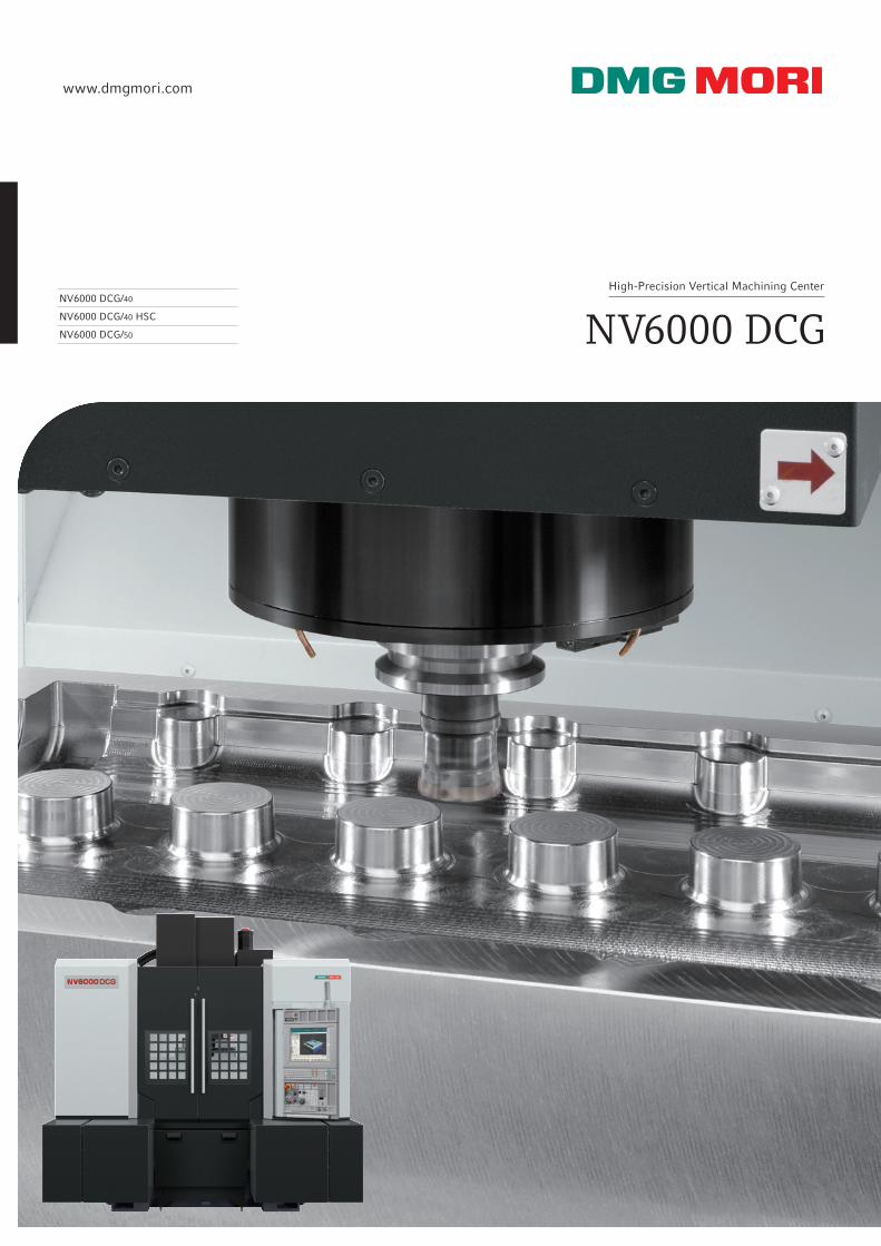
NV6000 DCG/40
NV6000 DCG/40 HSC
NV6000 DCG/50
High-Precision Vertical Machining Center
NV6000 DCG
www.dmgmori.com
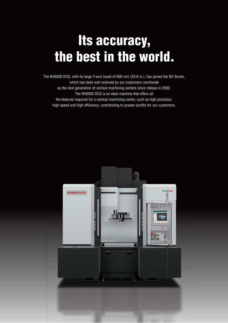
Its accuracy,the best in the world.
The NV6000 DCG, with its large Y-axis travel of 600 mm (23.6 in.), has joined the NV Series,which has been well received by our customers worldwide
as the next generation of vertical machining centers since release in 2002.The NV6000 DCG is an ideal machine that offers all
the features required for a vertical machining center, such as high precision,high speed and high efficiency, contributing to greater profits for our customers.
DCG: Driven at the Center of Gravity
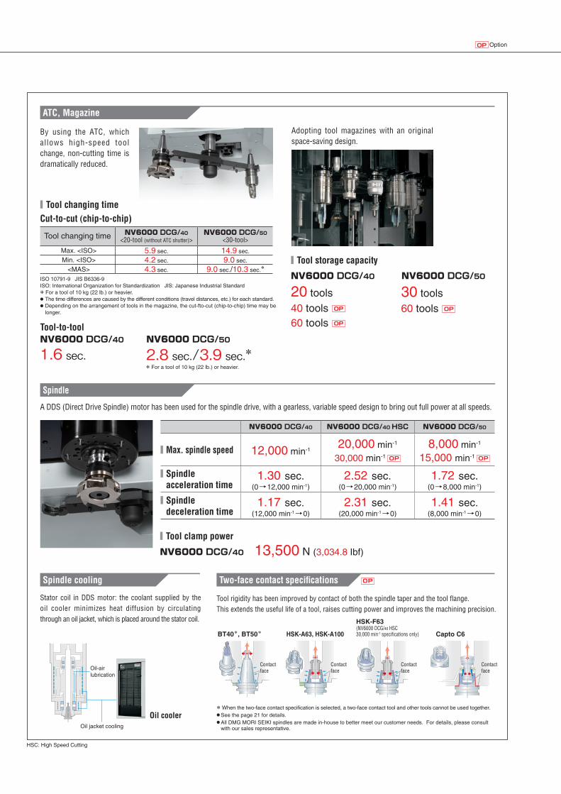
Despite its compact body, the NV6000 DCG ensures a large work envelope suitable for various workpieces.
Basic structure
Working areaMachine size
・ Improved surface quality ・Outstanding acceleration ・ Improved roundness ・Longer tool life
H
WD W:Width
D:DepthH:Height
■ Feedrate <X, Y and Z axes>
42 m/min (1,653.5 ipm)
42 m/min (1,653.5 ipm)<with AI contour control>
NV6000 DCG
NV6000 DCG
Driven at the Center of Gravity
TravelZ-axis: 450 mm(17.7 in.)
X-axis: 900 mm (35.4 in.)
Y-axis: 600 mm(23.6 in.)
Principal mechanisms
Principal mechanisms
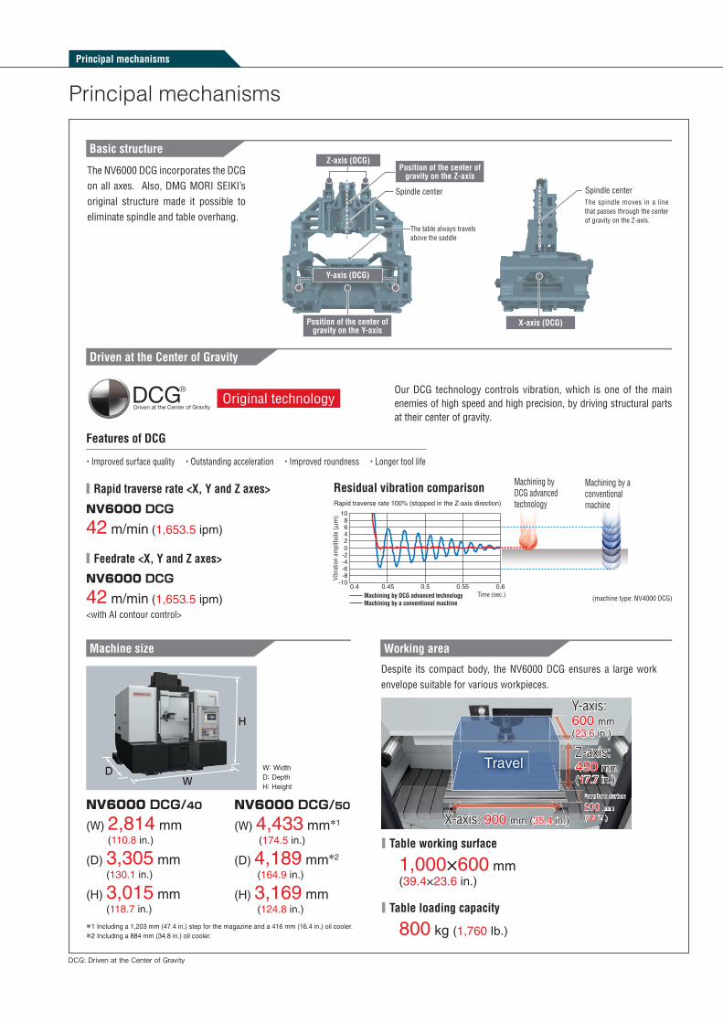
The NV6000 DCG incorporates the DCG on all axes. Also, DMG MORI SEIKI’s original structure made it possible to eliminate spindle and table overhang.
Spindle center
The table always travels above the saddle
Z-axis (DCG)Position of the center of
gravity on the Z-axis
Position of the center of gravity on the Y-axis
X-axis (DCG)
Spindle centerThe spindle moves in a line that passes through the center of gravity on the Z-axis.
Y-axis (DCG)
Original technologyOur DCG technology controls vibration, which is one of the main enemies of high speed and high precision, by driving structural parts at their center of gravity.
Features of DCG
■ Rapid traverse rate <X, Y and Z axes> Residual vibration comparisonRapid traverse rate 100% (stopped in the Z-axis direction)
─ Machining by DCG advanced technology─ Machining by a conventional machine
Time (sec.)
Vibr
atio
n am
plitu
de (μ
m)
-10-8-6-4-202468
10
0.4 0.45 0.5 0.55 0.6
Machining by DCG advanced technology
Machining by a conventional machine
*1 Including a 1,203 mm (47.4 in.) step for the magazine and a 416 mm (16.4 in.) oil cooler.*2 Including a 884 mm (34.8 in.) oil cooler.
NV6000 DCG/40
(W) 2,814 mm(110.8 in.)
(D) 3,305 mm(130.1 in.)
(H) 3,015 mm(118.7 in.)
NV6000 DCG/50
(W) 4,433 mm*1
(174.5 in.)
(D) 4,189 mm*2
(164.9 in.)
(H) 3,169 mm (124.8 in.)
■ Table working surface
1,000×600 mm(39.4×23.6 in.)
■ Table loading capacity
800 kg (1,760 Ib.)
(machine type: NV4000 DCG)
From table surface
200 mm(7.9 in.)
ATC, Magazine
Spindle
Spindle cooling Two-face contact specifications
■ Tool changing time
NV6000 DCG/40 NV6000 DCG/50
Cut-to-cut (chip-to-chip)
Tool-to-tool
■ Tool storage capacity
20 tools40 tools OP 60 tools OP
30 tools60 tools OP
NV6000 DCG/40 NV6000 DCG/50
■ Tool clamp power
NV6000 DCG/40
OP
NV6000 DCG/40 NV6000 DCG/40 HSC NV6000 DCG/50
■ Max. spindle speed 12,000 min-120,000 min-1
30,000 min-1 OP
8,000 min-1
15,000 min-1 OP
■ Spindleacceleration time
1.30 sec.(0→12,000 min-1)
2.52 sec.(0→20,000 min-1)
1.72 sec.(0→8,000 min-1)
■ Spindledeceleration time
1.17 sec.(12,000 min-1→0)
2.31 sec.(20,000 min-1→0)
1.41 sec.(8,000 min-1→0)
HSC: High Speed Cutting
OptionOP
By using the ATC, which al lows high-speed tool change, non-cutting time is dramatically reduced.
1.6 sec. 2.8 sec./3.9 sec.** For a tool of 10 kg (22 lb.) or heavier.
ISO 10791-9 JIS B6336-9ISO: International Organization for Standardization JIS: Japanese Industrial Standard* For a tool of 10 kg (22 lb.) or heavier.● The time differences are caused by the different conditions (travel distances, etc.) for each standard.● Depending on the arrangement of tools in the magazine, the cut-fto-cut (chip-to-chip) time may be
longer.
Tool changing time NV6000 DCG/40<20-tool (without ATC shutter)>
NV6000 DCG/50<30-tool>
Max. <ISO> 5.9 sec. 14.9 sec.
Min. <ISO> 4.2 sec. 9.0 sec.
<MAS> 4.3 sec. 9.0 sec./10.3 sec.*
Adopting tool magazines with an original space-saving design.
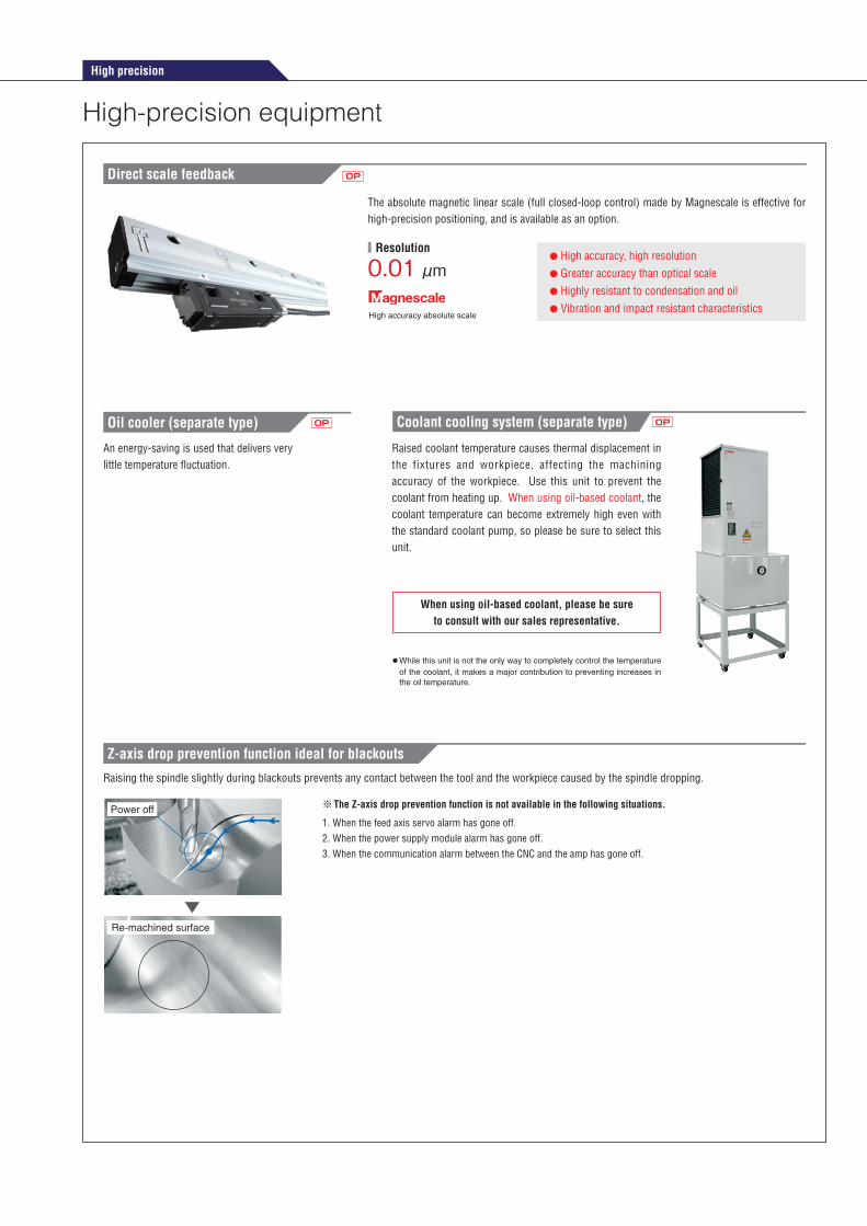
A DDS (Direct Drive Spindle) motor has been used for the spindle drive, with a gearless, variable speed design to bring out full power at all speeds.
13,500 N (3,034.8 Ibf)
Stator coil in DDS motor: the coolant supplied by the oil cooler minimizes heat diffusion by circulating through an oil jacket, which is placed around the stator coil.
Oil jacket cooling
Oil-air lubrication
Oil cooler
Tool rigidity has been improved by contact of both the spindle taper and the tool flange. This extends the useful life of a tool, raises cutting power and improves the machining precision.
Contact face
Contact face
Contact face
Contact face
* When the two-face contact specification is selected, a two-face contact tool and other tools cannot be used together.● See the page 21 for details.● All DMG MORI SEIKI spindles are made in-house to better meet our customer needs. For details, please consult
with our sales representative.
HSK-A63, HSK-A100BT40*, BT50*
HSK-F63(NV6000 DCG/40 HSC30,000 min-1 specifications only) Capto C6
High precision
High-precision equipment
OPDirect scale feedback
Coolant cooling system (separate type)Oil cooler (separate type) OPOP
※ The Z-axis drop prevention function is not available in the following situations.
1. When the feed axis servo alarm has gone off.2. When the power supply module alarm has gone off.3. When the communication alarm between the CNC and the amp has gone off.
Raising the spindle slightly during blackouts prevents any contact between the tool and the workpiece caused by the spindle dropping.
Z-axis drop prevention function ideal for blackouts
Re-machined surface
Power off
Pos
ition
(m
m)
-0.08
Time (s)
0.24
-0.04
0.20
0.00
0.16
0.04
0.120.08
-150
250
-100
200
-50
150
0
10050
TC
MD
0.95 0.955 0.96 0.965 0.97 0.975 0.98 0.985 0.99 0.995 1
Blackout
After blackout countermeasure (Z-axis raised)
RiseTCMD
PositionPos
ition
(m
m)
Time (s)
TC
MD
1.18 1.2 1.22 1.24 1.26 1.28 1.30 1.32 1.34 1.36 1.38-0.40
0.40
-0.30
0.30
-0.20
0.20
-0.10
0.100.00
4.5
3.0
7.0
3.5
6.5
4.0
6.05.55.0
Blackout
Before blackout countermeasure
TCMD
Position
● While this unit is not the only way to completely control the temperature of the coolant, it makes a major contribution to preventing increases in the oil temperature.
When using oil-based coolant, please be sure to consult with our sales representative.
Raised coolant temperature causes thermal displacement in the fixtures and workpiece, affecting the machining accuracy of the workpiece. Use this unit to prevent the coolant from heating up. When using oil-based coolant, the coolant temperature can become extremely high even with the standard coolant pump, so please be sure to select this unit.
An energy-saving is used that delivers very little temperature fluctuation.
● High accuracy, high resolution● Greater accuracy than optical scale ● Highly resistant to condensation and oil● Vibration and impact resistant characteristics
High accuracy absolute scale
0.01 μm
The absolute magnetic linear scale (full closed-loop control) made by Magnescale is effective for high-precision positioning, and is available as an option.
■ Resolution
Improved workability/Maintenance
Maintenance
Accessibility
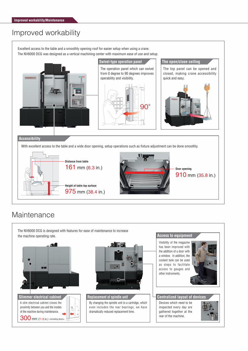
Excellent access to the table and a smoothly opening roof for easier setup when using a crane. The NV6000 DCG was designed as a vertical machining center with maximum ease of use and setup.
Improved workability
Swivel-type operation panel
The operation panel which can swivel from 0 degree to 90 degrees improves operability and visibility.
90°
The open/close ceiling
The top panel can be opened and closed, making crane accessibility quick and easy.
With excellent access to the table and a wide door opening, setup operations such as fixture adjustment can be done smoothly.
910 mm (35.8 in.)
Door opening161 mm (6.3 in.)
975 mm (38.4 in.)
Distance from table
Height of table top surface
Access to equipment
Slimmer electrical cabinet
The NV6000 DCG is designed with features for ease of maintenance to increase the machine operating rate.
300 mm (11.8 in.) <including doors>
A slim electrical cabinet closes the proximity between you and the insides of the machine during maintenance.
Replacement of spindle unitBy changing the spindle unit to a cartridge, which even includes the rear bearings, we have dramatically reduced replacement time.
Centralized layout of devicesDevices which need to be inspected every day are gathered together at the rear of the machine.
Visibility of the magazine has been improved with the addition of a door with a window. In addition, the coolant tank can be used as steps to faci l i tate access to gauges and other instruments.
Chip conveyor
OP
OP
Peripheral equipment
Peripheral equipment
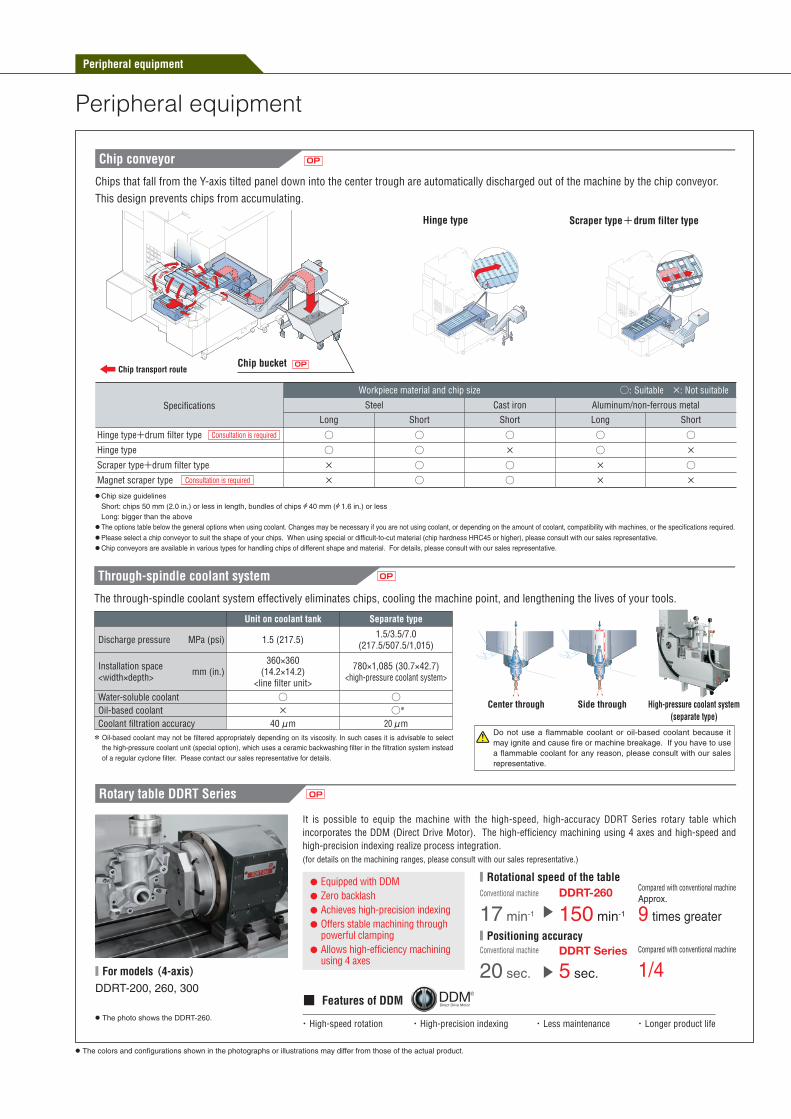
Chips that fall from the Y-axis tilted panel down into the center trough are automatically discharged out of the machine by the chip conveyor.This design prevents chips from accumulating.
Chip transport route
Hinge type Scraper type+drum filter type
Chip bucket
Specifications
Workpiece material and chip size ○: Suitable ×: Not suitable
Steel Cast iron Aluminum/non-ferrous metal
Long Short Short Long Short
Hinge type+drum filter type ○ ○ ○ ○ ○Hinge type ○ ○ × ○ ×Scraper type+drum filter type × ○ ○ × ○Magnet scraper type × ○ ○ × ×
Consultation is required
Consultation is required
● Chip size guidelines Short: chips 50 mm (2.0 in.) or less in length, bundles of chips A 40 mm (A 1.6 in.) or less Long: bigger than the above
● The options table below the general options when using coolant. Changes may be necessary if you are not using coolant, or depending on the amount of coolant, compatibility with machines, or the specifications required.● Please select a chip conveyor to suit the shape of your chips. When using special or difficult-to-cut material (chip hardness HRC45 or higher), please consult with our sales representative.● Chip conveyors are available in various types for handling chips of different shape and material. For details, please consult with our sales representative.
Through-spindle coolant system
Center through Side through High-pressure coolant system(separate type)
OP
The through-spindle coolant system effectively eliminates chips, cooling the machine point, and lengthening the lives of your tools.
■ For models (4-axis)DDRT-200, 260, 300
● The photo shows the DDRT-260.
It is possible to equip the machine with the high-speed, high-accuracy DDRT Series rotary table which incorporates the DDM (Direct Drive Motor). The high-efficiency machining using 4 axes and high-speed and high-precision indexing realize process integration.(for details on the machining ranges, please consult with our sales representative.)
Rotary table DDRT Series OP
● Equipped with DDM● Zero backlash● Achieves high-precision indexing● Offers stable machining through
powerful clamping● Allows high-efficiency machining
using 4 axes
■ Rotational speed of the table
150 min-117 min-1
Approx.
9 times greater■ Positioning accuracy
5 sec.20 sec. 1/4DDRT Series
DDRT-260Conventional machine
Conventional machine
Compared with conventional machine
Compared with conventional machine
● The colors and configurations shown in the photographs or illustrations may differ from those of the actual product.
* Oil-based coolant may not be filtered appropriately depending on its viscosity. In such cases it is advisable to select the high-pressure coolant unit (special option), which uses a ceramic backwashing filter in the filtration system instead of a regular cyclone filter. Please contact our sales representative for details.
Unit on coolant tank Separate type
Discharge pressure�� MPa (psi) 1.5 (217.5) 1.5/3.5/7.0(217.5/507.5/1,015)
Installation space<width×depth> mm (in.)
360×360(14.2×14.2)
<line filter unit>
780×1,085 (30.7×42.7)<high-pressure coolant system>
Water-soluble coolant ○ ○Oil-based coolant × ○*
Coolant filtration accuracy 40 μm 20 μm
・ High-speed rotation ・ High-precision indexing ・ Less maintenance ・ Longer product life
■ Features of DDM
Do not use a flammable coolant or oil-based coolant because it may ignite and cause fire or machine breakage. If you have to use a flammable coolant for any reason, please consult with our sales representative.
OptionOP
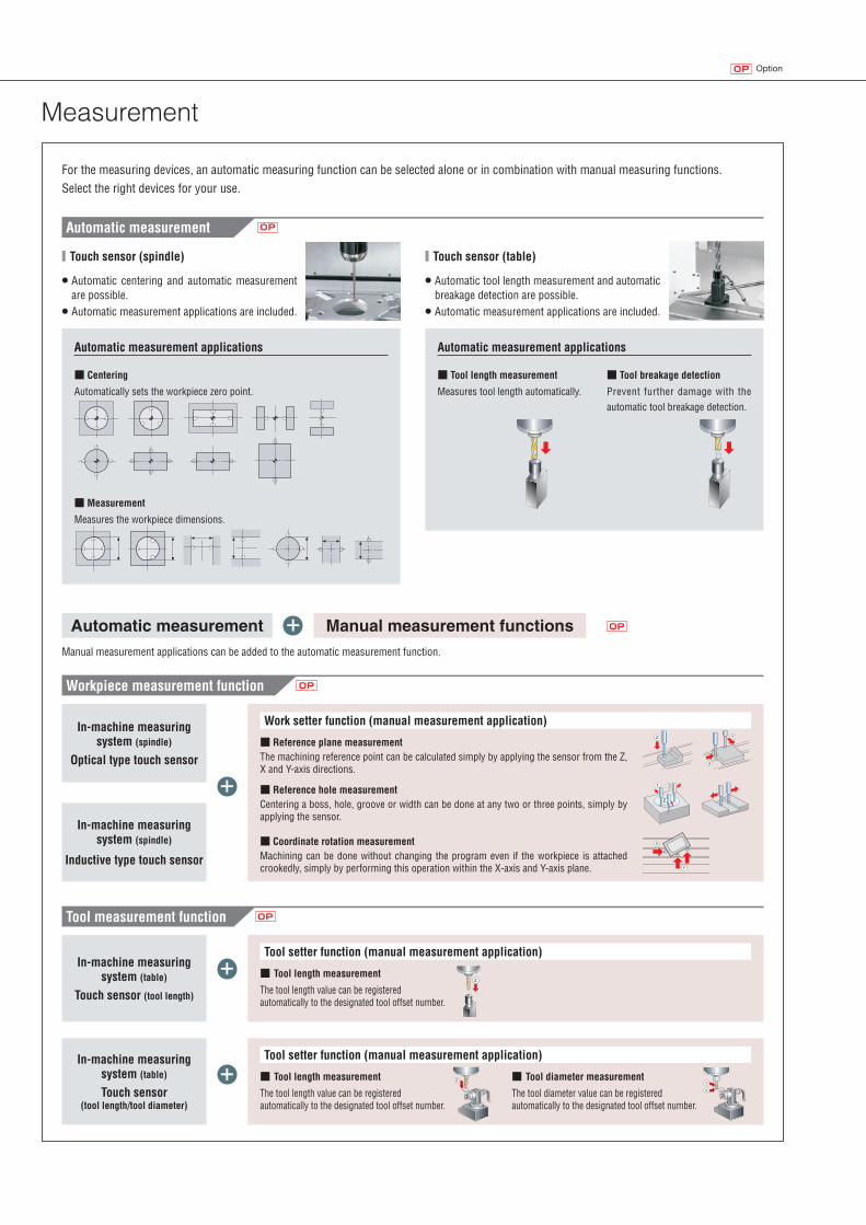
Measurement
In-machine measuring system (table)
Touch sensor (tool length/tool diameter)
In-machine measuring system (table)
Touch sensor (tool length)
In-machine measuring system (spindle)
Inductive type touch sensor
For the measuring devices, an automatic measuring function can be selected alone or in combination with manual measuring functions. Select the right devices for your use.
Manual measurement applications can be added to the automatic measurement function.
Work setter function (manual measurement application)
+
+
+
+
OP
In-machine measuring system (spindle)
Optical type touch sensor
OPAutomatic measurement
Workpiece measurement function
Tool measurement function
Automatically sets the workpiece zero point.
Measures the workpiece dimensions.
■ Centering
■ Measurement
Automatic measurement applications
■ Touch sensor (spindle)
Measures tool length automatically. Prevent further damage with the automatic tool breakage detection.
■ Tool length measurement ■ Tool breakage detection
Automatic measurement applications
Automatic measurement Manual measurement functions
The machining reference point can be calculated simply by applying the sensor from the Z, X and Y-axis directions.
The tool length value can be registered automatically to the designated tool offset number.
The tool length value can be registered automatically to the designated tool offset number.
The tool diameter value can be registered automatically to the designated tool offset number.
Centering a boss, hole, groove or width can be done at any two or three points, simply by applying the sensor.
Machining can be done without changing the program even if the workpiece is attached crookedly, simply by performing this operation within the X-axis and Y-axis plane.
■ Reference plane measurement
■ Tool length measurement
■ Tool length measurement ■ Tool diameter measurement
■ Reference hole measurement
■ Coordinate rotation measurement
Tool setter function (manual measurement application)
Tool setter function (manual measurement application)
OP
OP
● Automatic centering and automatic measurementare possible.
● Automatic measurement applications are included.
● Automatic tool length measurement and automatic breakage detection are possible.
● Automatic measurement applications are included.
■ Touch sensor (table)

Peripheral equipment
2-station turn-type APC (NV6000 DCG/40) OP
OP
OP
■ Machine front ■ Machine rear
Transfer systems
● The APC uses a 2-station turn-type design. Cycle time is shorter than that of a shuttle-type machine.● A new design allows access from the back of the machine when setting up the APC. This contributes to space savings.
Pallet size
900×600 mm (35.4×23.6 in.)
Pallet changing time
25 sec.● To prevent APC interference, this specification includes
time required for the spindle protection tool to be moveduntil after the APC turning is complete.
● When there are adjacent tools. Depending on the arrangement of tools in the magazine, the APC time may be longer.
● Without ATC shutter
Tool storage capacity
40/60 tools● For APC speci f icat ions, a dummy tool
which is mounted on the spindle duringAPC operation is included.
● The photo shows the NV4000 DCG.● The photo shows the NVD6000 DCG/40.
● The illustration shows the NV4000 DCG.
Setup station
Chip conveyor(external)
● When APC is selected, 200 mm (7.9 in.) raised column specifications are required.
OPChip bucket
Consultation is required
Robots make workpiece loading and unloading moreefficient, improving productivity.
Workpiece transfer robot
Reduced consumption of lubricating oil Power-saving function
■ Oil-bath ATCAn oil-bath design has been integrated into the ATC unitdesign. Compared with conventional oil drip designs, the amount of lubricating oil used has been radically reduced.
Eco-friendly design
If the keyboard is not touched after a certain amount of time and NC operation is not being performed, power is cut off to the servo motor, the spindle, the coolant pump and the chip conveyor, thereby saving energy.
If the operation panel is not touched for a certain amount of time, the interior light automatically turns off. This saves energy and lengthens the life of the machine lights.
Automatic sleep function
Automatic machine light function
Energy-saving settings screen
Reduction in environmental burden ● The colors and configurations shown in the photographs or illustrations may differ from those of the actual product.
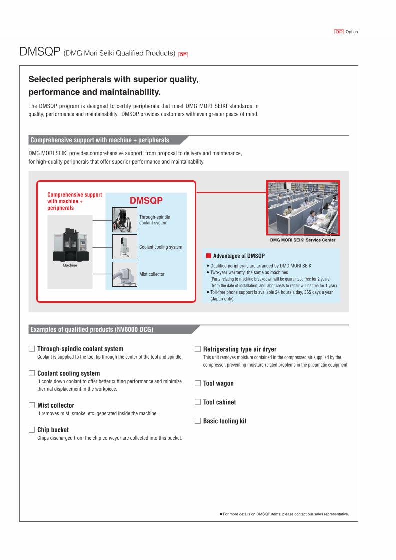
DMSQP (DMG Mori Seiki Qualified Products) OP
The DMSQP program is designed to certify peripherals that meet DMG MORI SEIKI standards in quality, performance and maintainability. DMSQP provides customers with even greater peace of mind.
Selected peripherals with superior quality,
performance and maintainability.
● For more details on DMSQP items, please contact our sales representative.
Examples of qualified products (NV6000 DCG)
□ Coolant cooling systemIt cools down coolant to offer better cutting performance and minimize thermal displacement in the workpiece.
□ Through-spindle coolant systemCoolant is supplied to the tool tip through the center of the tool and spindle.
□ Mist collectorIt removes mist, smoke, etc. generated inside the machine.
□ Tool wagon
□ Tool cabinet
□ Basic tooling kit
□ Refrigerating type air dryerThis unit removes moisture contained in the compressed air supplied by the compressor, preventing moisture-related problems in the pneumatic equipment.
□ Chip bucketChips discharged from the chip conveyor are collected into this bucket.
DMG MORI SEIKI provides comprehensive support, from proposal to delivery and maintenance, for high-quality peripherals that offer superior performance and maintainability.
Comprehensive support with machine + peripherals
Comprehensive support with machine + peripherals
DMG MORI SEIKI Service Center
■ Advantages of DMSQP● Qualified peripherals are arranged by DMG MORI SEIKI● Two-year warranty, the same as machines
( Parts relating to machine breakdown will be guaranteed free for 2 years from the date of installation, and labor costs to repair will be free for 1 year)
● Toll-free phone support is available 24 hours a day, 365 days a year (Japan only)
Through-spindle coolant system
Coolant cooling system
Mist collector
DMSQP
Machine
OptionOP
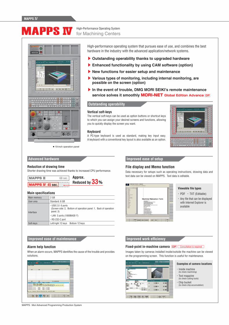
for Machining Centers
MAPPS: Mori Advanced Programming Production System
High-Performance Operating System
High-performance operating system that pursues ease of use, and combines the best hardware in the industry with the advanced application/network systems.
Vertical soft-keys
Keyboard
The vertical soft-keys can be used as option buttons or shortcut keys to which you can assign your desired screens and functions, allowing you to quickly display the screen you want.
A PC-type keyboard is used as standard, making key input easy. A keyboard with a conventional key layout is also available as an option.
▶ Outstanding operability thanks to upgraded hardware
▶ Enhanced functionality by using CAM software (option)
▶ New functions for easier setup and maintenance
▶ Various types of monitoring, including internal monitoring, arepossible on the screen (option)
▶ In the event of trouble, DMG MORI SEIKI’s remote maintenanceservice solves it smoothly MORI-NET Global Edition Advance OP
Outstanding operability
Alarm help functionWhen an alarm occurs, MAPPS identifi es the cause of the trouble and provides solutions.
Improved ease of maintenance
File display and Memo functionData necessary for setups such as operating instructions, drawing data and text data can be viewed on MAPPS. Text data is editable.
Improved ease of setup
Viewable file types
・ PDF ・ TXT (Editable)
・ Any fi le that can be displayed with Internet Explorer is available
Improved work effi ciency
Examples of camera locations
・ Inside machine (to check machining)
・ Tool magazine (to check cutting tools)
・ Chip bucket (to check chip accumulation)
Fixed-point in-machine cameraImages taken by cameras installed inside/outside the machine can be viewed on the programming screen. This function is useful for maintenance.
Consultation is requiredOP
● 19-inch operation panel
Reduction of drawing time
Main specifications
Shorter drawing time was achieved thanks to increased CPU performance.
Main memory 2 GB
User area Standard: 6 GB
Interface
・ USB 2.0 6 ports(Screen side: 2, Bottom of operation panel: 1, Back of operation panel: 3)
・LAN 2 ports (1000BASE-T)
・RS-232-C port
Soft-keys Left/right 12 keys Bottom 12 keys
Advanced hardware
Approx. Reduced by 33%
68 sec.
45 sec.MAPPS Ⅳ
MAPPS Ⅲ
MAPPS Ⅳ
■ Machining menu ■ Islands, open pockets OP■ Contour input
■ DXF import function*1 OP
■ List display function
■ MORI-POST advanced mode OP
■ Remote Desktop <Patent pending> ■ License borrowing system ■ Support system
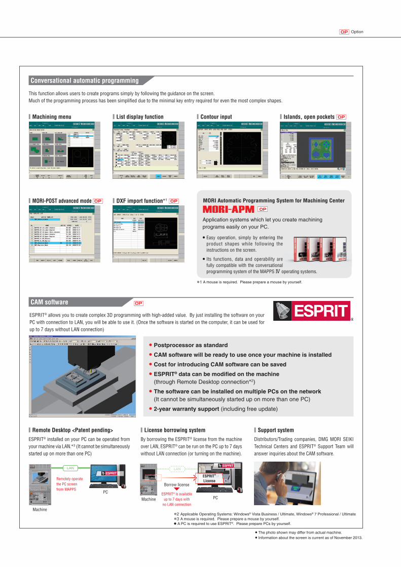
This function allows users to create programs simply by following the guidance on the screen.Much of the programming process has been simplifi ed due to the minimal key entry required for even the most complex shapes.
ESPRIT® allows you to create complex 3D programming with high-added value. By just installing the software on your PC with connection to LAN, you will be able to use it. (Once the software is started on the computer, it can be used for up to 7 days without LAN connection)
ESPRIT® installed on your PC can be operated from your machine via LAN.*3 (It cannot be simultaneously started up on more than one PC)
By borrowing the ESPRIT® license from the machine over LAN, ESPRIT® can be run on the PC up to 7 days without LAN connection (or turning on the machine).
Distributors/Trading companies, DMG MORI SEIKI Technical Centers and ESPRIT® Support Team will answer inquiries about the CAM software.
Conversational automatic programming
CAM software
*2 Applicable Operating Systems: Windows® Vista Business / Ultimate, Windows® 7 Professional / Ultimate*3 A mouse is required. Please prepare a mouse by yourself.● A PC is required to use ESPRIT®. Please prepare PCs by yourself.
● Postprocessor as standard● CAM software will be ready to use once your machine is installed● Cost for introducing CAM software can be saved● ESPRIT® data can be modifi ed on the machine
(through Remote Desktop connection*2)
● The software can be installed on multiple PCs on the network(It cannot be simultaneously started up on more than one PC)
● 2-year warranty support (including free update)
MORI Automatic Programming System for Machining Center
OP
Application systems which let you create machining programs easily on your PC.
● Easy operation, simply by entering theproduct shapes while following theinstructions on the screen.
● Its functions, data and operability arefully compatible with the conversationalprogramming system of the MAPPS Ⅳ operating systems.
LAN LAN
PCPC
ESPRIT® is available up to 7 days with
no LAN connection
ESPRIT®
LicenseRemotely operate the PC screen from MAPPS
Borrow license
OP
● The photo shown may differ from actual machine.● Information about the screen is current as of November 2013.
Machine
Machine
ESPRITESPRIT®
LicenseLicenseLicense
OptionOP
*1 A mouse is required. Please prepare a mouse by yourself.
MAPPS Ⅳ
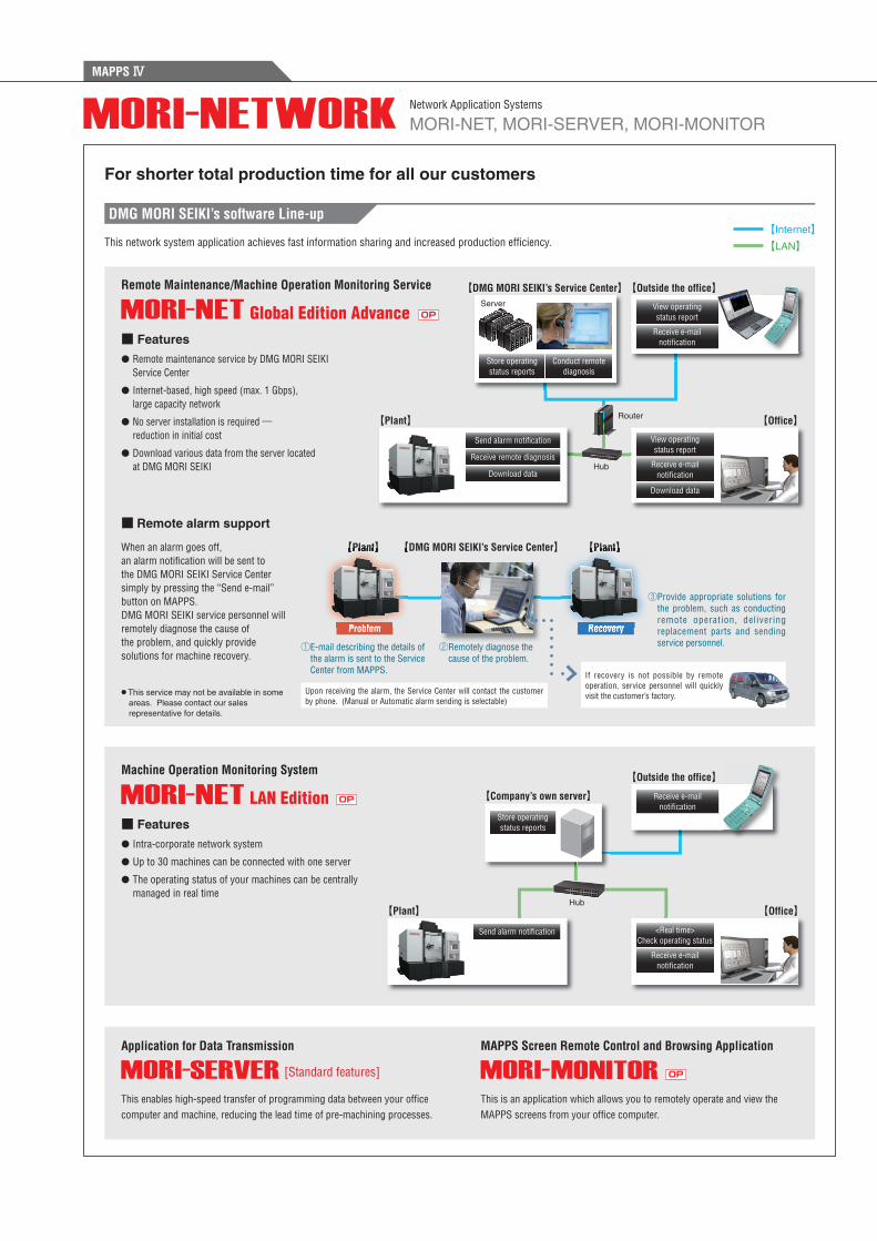
This is an application which allows you to remotely operate and view the MAPPS screens from your office computer.
This enables high-speed transfer of programming data between your office computer and machine, reducing the lead time of pre-machining processes.
DMG MORI SEIKI’s software Line-up
For shorter total production time for all our customers
This network system application achieves fast information sharing and increased production effi ciency.
Remote Maintenance/Machine Operation Monitoring Service
Machine Operation Monitoring System
Application for Data Transmission MAPPS Screen Remote Control and Browsing Application
【Plant】
【Plant】
[Standard features]
Receive e-mail notifi cation
View operating status report
Receive e-mail notifi cation
【DMG MORI SEIKI’s Service Center】
【Company’s own server】
Server
Hub
Router
● Remote maintenance service by DMG MORI SEIKI Service Center
● Internet-based, high speed (max. 1 Gbps), large capacity network
● No server installation is required ―reduction in initial cost
● Download various data from the server located at DMG MORI SEIKI
● Intra-corporate network system
● Up to 30 machines can be connected with one server
● The operating status of your machines can be centrally managed in real time
■ Features
■ Features
【Office】
【Outside the office】
【Outside the office】
Receive remote diagnosis
Download data
Download data
Send alarm notifi cation
Hub
OP
OP
OP
Store operating status reports
Send alarm notifi cation
【Office】
Receive e-mail notifi cation
<Real time>Check operating status
■ Remote alarm support
When an alarm goes off, an alarm notification will be sent to the DMG MORI SEIKI Service Center simply by pressing the “Send e-mail” button on MAPPS. DMG MORI SEIKI service personnel will remotely diagnose the cause of the problem, and quickly provide solutions for machine recovery.
【Plant】 【Plant】【DMG MORI SEIKI’s Service Center】
① E-mail describing the details of the alarm is sent to the Service Center from MAPPS.
② Remotely diagnose the cause of the problem.
③ Provide appropriate solutions forthe problem, such as conductingremote operation, deliveringreplacement parts and sendingservice personnel.②
Problem Recovery
Upon receiving the alarm, the Service Center will contact the customer by phone. (Manual or Automatic alarm sending is selectable)
If recovery is not possible by remote operation, service personnel will quickly visit the customer’s factory.● This service may not be available in some
areas. Please contact our sales representative for details.
Store operating status reports
Conduct remote diagnosis
View operating status report
Receive e-mail notifi cation
MORI-NET, MORI-SERVER, MORI-MONITORNetwork Application Systems
【Internet】 【LAN】
NETWORK_E01_cs5.indd 1 13/09/19 19:57
MAPPS Ⅳ
【Plant】 【
Problem
【Plant】
Recovery

OptionOP
DMG MORI SEIKI’s new proposal, ACT, is designed to strengthen connections between machine tools and peripheral equipment by standardizing communication and software of the entire system. With ACT, standardization of interfaces of peripherals, simplified wiring, and labor saving can be achieved.
This industrial network using the standard Ethernet (TCP/IP) offers high speed and reliable connection. Simple Plug and Play connections, which are made available just by connecting to the hub through MAPPS, enable you to build a system easily.The use of standard cables also helps to reduce costs.
MTConnect, which was introduced by the Association for Manufacturing Technology (AMT) in 2008, is a new XML (Extensible Markup Language) based communication protocol that offers an open interface. This interface allows you to build a system to monitor the operating status of your machines.
Advanced Communication Technology
MAPPS EtherNet/IP I/F OP
MAPPS MTConnect I/F
Advanced Communication Technology (ACT) connects machine tool and peripheral devices
■ Easy system construction■ Connection with existing devices■ Inexpensive devices
You can check the operating history on the Gantt chart screen.
● Connections between a machine and peripheral equipment become easy because standard LAN cables are used
● Thanks to increased versatility, your peripheral equipment can be used even when the machine tools are replaced by new ones
● Reliability is significantly increased by reducing the number of I/O cables
● Open communication interface allows you to access to your company’s system
● This makes it possible for you to build a system to monitor the operating status of your machines via the Internet
■ Features
■ Features
■ System examples
Operating status can be checked in real time.
Your machines are displayed all at once, allowing you to quickly call up the machine you wish to check.
■ Application examples
Industrial Network for Peripheral Equipment Control
Communication Interface for Monitoring Machine Operation
● A server and application must be prepared by the customer.● For introduction of MTConnect, separate consultation is required.
【Internet】 【LAN】
Other devices
Measuring equipment Tool presetter
Machine
Hub
Robot
Adapter 1
ServerAdapter 2
Adapter 3
Outside the offi ce
Offi ce
Other terminal deviceAgent 1
Agent 2
Application
Router
NETWORK_E01_cs5.indd 2 13/09/19 19:57
OptionOP
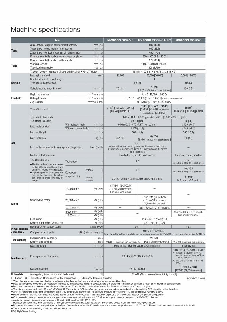
Machine specificationsItem NV6000 DCG/40 NV6000 DCG/40 HSC NV6000 DCG/50
Travel
X-axis travel <longitudinal movement of table> mm (in.) 900 (35.4)Y-axis travel <cross movement of saddle> mm (in.) 600 (23.6)Z-axis travel <vertical movement of spindle head> mm (in.) 450 (17.7)Distance from table surface to spindle gauge plane mm (in.) 200ー650 (7.9ー25.6)
Table
Distance from table surface to floor surface mm (in.) 975 (38.4)Working surface mm (in.) 1,000×600 (39.4×23.6)Table loading capacity kg (lb.) 800 (1,760)Table surface configuration <T slots width×pitch×No. of T slots> 18 mm×100 mm×6 (0.7 in.×3.9 in.×6)
Spindle
Max. spindle speed min-1 12,000 20,000 [30,000] 8,000 [15,000]Number of spindle speed ranges 1Type of spindle taper hole No. 40 No. 50
Spindle bearing inner diameter mm (in.) 70 (2.8) 70 (2.8)[60 (2.4) <30,000 min-1 specifications>] 100 (3.9)
FeedrateRapid traverse rate mm/min (ipm) X, Y, Z: 42,000 (1,653.5)Cutting feedrate mm/min (ipm) X, Y, Z: 1ー42,000 (0.04ー1,653.5) <with AI contour control>
Jog feedrate mm/min (ipm) 0ー5,000 (0ー197.0) <20 steps>
ATC
Type of tool shank BT40* [HSK-A63] [DIN40]
[CAT40] [Capto C6]
BT40* [HSK-A63] [DIN40]
[CAT40] [HSK-F63 <30,000 min-1 specifications>] [Capto C6]
BT50*
[HSK-A100] [DIN50] [CAT50]
Type of retention knob DMG MORI SEIKI 90° type [45° (MAS-Ⅰ)] [60°(MAS-Ⅱ)] [HSK]Tool storage capacity 20 [40] [60] 30 [60]
Max. tool diameterWith adjacent tools mm (in.) A 80 (A 3.1) [A 70 (A 2.7) <40-, 60-tool>] A 120 (A 4.7)Without adjacent tools mm (in.) A 125 (A 4.9) A 240 (A 9.4)
Max. tool length mm (in.) 300 (11.8) 350 (13.7)
Max. tool mass kg (lb.) 8 (17.6) 8 (17.6)[3 (6.6) <30,000 min-1 specifications>] 20 (44)
Max. tool mass moment <from spindle gauge line> N・m (ft・lbf)11 (8.1)
<a tool with a mass moment greater than the maximum tool massmoment may cause problems during ATC operations even if it satisfie
other conditions.>
−
Method of tool selection Fixed address, shorter route access Technical memory random
Tool changing time
● The time differences are causedby the different conditions (traveldistances, etc.) for each standard.
● Depending on the arrangement oftools in the magazine, the cut-to-cut (chip-to-chip) time may belonger.
Tool-to-tool s 1.6 2.8/3.9<for a tool of 10 kg (22 lb.) or heavier>
Cut-to-cut(chip-to-chip)
<MAS> s 4.3 9.0/10.3<for a tool of 10 kg (22 lb.) or heavier>
ISO 10791-9
JIS B6336-9s 20-tool <without ATC shutter>: 5.9 <max.>/4.2 <min.> 30-tool:
14.9 <max.>/9.0 <min.>
MotorSpindle drive motor
12,000 min-1 kW (HP)18.5/15/11 (24.7/20/15) <10 min/30 min/cont> {high-speed winding side}
−
−
20,000 min-1 kW (HP) −18.5/15/11 (24.7/20/15) <10 min/30 min/cont> {high-speed winding side}
[30,000 min-1] kW (HP) − 18.5/13 (24.7/17.3) <1 min/cont> −8,000 min-1 kW (HP) − 30/22 (40/30) <30 min/cont>
{high-speed winding side}[15,000 min-1] kW (HP)Feed motor kW (HP) X: 4.5 (6) Y, Z: 4.0 (5.3)Coolant pump motor <50/60 Hz> kW (HP) 0.6 (0.8)/1.02 (1.36)
Power sources <standard>
Electrical power supply <cont> I94056D03 (kVA) 36.1 49.1
Compressed air supply MPa (psi), L/min (gpm) 0.5 (72.5), 200 (52.8){when the tool tip air blow is regularly used, air supply of more than 300 L/min (79.2 gpm) is separately required>} <ANR>
Tank capacityHydraulic oil tank capacity L (gal.) 20 (5.3)Coolant tank capacity L (gal.) 345 (91.1) <without chip conveyor> [600 (158.4) <APC specifications>] 345 (91.1) <without chip conveyor>
Machine size
Machine height mm (in.) 3,015 (118.7) [3,215 (126.6) <APC specifications>] 3,169 (124.8)
Floor space <width×depth> mm (in.) 2,814×3,305 (110.8×130.1)
4,433 (174.5) *1×4,189 (164.9)*2
*1 Including a 1,203 mm (47.4 in.) step for the magazine and a 416 mm (16.4 in.) oil cooler.
*2 Including a 884 mm (34.8 in.) oil cooler.
Mass of machine kg (lb.) 10,160 (22,352) 10,970 (24,134)[12,300 (27,060) <60-tool>]
Noise data A-weighted, time-average radiated sound dB 61ー80 (Measurement uncertainty is 4 dB)[ ]Option ISO:International Organization for Standardization JIS: Japanese Industrial Standard NV6000DCG (200901)
* When the two-face contact specification is selected, a two-face contact tool and other tools cannot be used together.● Max. spindle speed: depending on restrictions imposed by the workpiece clamping device, fixture and tool used, it may not be possible to rotate at the maximum spindle speed.● Max. tool diameter: the maximum tool diameter is limited to 170 mm (6.6 in.) or less when using a No. 50 taper spindle at 10,000 min-1 or higher.● Tool storage capacity (40 tools, 60 tools) <NV6000 DCG/40>: with the APC specifications, a dummy tool to be mounted on the spindle during APC operation will be included.● ANR: ANR refers to a standard atmospheric state; i. e., temperature at 20 °C (68 ˚F), absolute pressure at 101.3 kPa (14.7 psi) and relative humidity at 65%.● Power sources, machine size: the actual values may differ from those specified in the catalogue, depending on the optional features and peripheral equipment. ● Compressed air supply: please be sure to supply clean compressed air <air pressure: 0.7 MPa (101.5 psi), pressure dew point: 10 °C (50 °F) or below>.● A criterion capacity to select a compressor is 90 L/min (23.8 gpm) per 0.75 kW (1 HP).
However, this figure may differ depending on the type of compressors and options attached. For details, please check the compressor specifications.● Noise data: the measurement was performed at the front of the machine with a No. 40 spindle taper and a maximum spindle speed of 12,000 min-1. Please contact our sales representative for details.● The information in this catalog is valid as of November 2013. HSC: High Speed Cutting

EXPORTATION: All contracts are subject to export permit by the Government of Japan. Customer shall comply with the laws and regulations of the exporting country governing the exportation or re-exportation of the Equipment, including but not limited to the Export Administration Regulations. The Equipment is subject to export restrictions imposed by Japan and other exporting countries and the Customer will not export or permit the export of the Equipment anywhere outside the exporting country without proper government authorization. To prevent the illegal diversion of the Equipment to individuals or nations that threaten international security, it may include a “Relocation Machine Security Function” that automatically disables the Equipment if it is moved following installation. If the Equipment is so-disabled, it can only be re-enabled by contacting DMG MORI SEIKI or its distributor representative. DMG MORI SEIKI and its distributor representative may refuse to re-enable the Equipment if it determines that doing so would be an unauthorized export of technology or otherwise violates applicable export restrictions. DMG MORI SEIKI and its distributor representative shall have no obligation to re-enable such Equipment. DMG MORI SEIKI and its distributor representative shall have no liability (including for lost profits or business interruption or under the limited service warranty included herein) as a result of the Equipment being disabled.
<Precautions for Machine Relocation>
● DCG, DDM, BMT and ORC are trademarks or registered trademarks of DMG MORI SEIKI CO., LTD. in Japan, the USA and other countries.● If you have any questions regarding the content, contact our sales representative.● The information in this catalog is valid as of November 2013. Designs and specifications are subject to changes without notice.● The machines shown in the catalog may differ from the actual machines. The location and the size of the nameplates may also differ from the actual machines, or the nameplates may not be
attached to some machines.● DMG MORI SEIKI is not responsible for differences between the information in the catalog and the actual machine.
2-year warranty, twice the peace of mind. For machines delivered outside of Japan, parts relating to machine breakdown will be guaranteed free for 2 years from the date of installation, and labor costs to repair will be free for 1 year. Please contact our sales representative for details.
Nagoya Head Office □ 2-35-16 Meieki, Nakamura-ku, Nagoya City, Aichi 450-0002, Japan Phone: +81-52-587-1811
Tokyo Branch □ 18th floor, Shinagawa Intercity Tower A, 2-15-1 Konan Minato-ku, Tokyo 108-6018, Japan Phone: +81-3-5460-3570Nara Campus Nara No. 1 Plant □ 362 Idono-cho, Yamato-Koriyama City, Nara 639-1183, Japan Phone: +81-743-53-1121
Nara No. 2 Plant □ 106 Kita-Koriyama-cho, Yamato-Koriyama City, Nara 639-1160, Japan Phone: +81-743-53-1125Iga Campus □ 201 Midai, Iga City, Mie 519-1414, Japan Phone: +81-595-45-4151Chiba Campus □ 488-19 Suzumi-cho, Funabashi City, Chiba 274-0052, Japan Phone: +81-47-410-8800
DMG MORI SEIKI CO., LTD.
NV6000-EE01ABD
D.1311.CDT.0000
Created in Japan