Embed Size (px)
DESCRIPTION
High Precision Temperature Controller. Group 13 Ashley Desiongco Stacy Glass Martin Trang Cara Waterbury. Objectives. Replace COTS controller More Efficient More Economical Use modern technology Part selection must consider production life. Application. Extended Area. Cavity . - PowerPoint PPT Presentation
Citation preview

HIGH PRECISION TEMPERATURE CONTROLLERGroup 13Ashley DesiongcoStacy GlassMartin TrangCara Waterbury

Objectives• Replace COTS controller
• More Efficient• More Economical
• Use modern technology• Part selection must consider production life

Application
Extended Area
• Uses 2 Type T T/C or 4 RTDs
• From -30°C to 700°C
Cavity
• Uses 2 Type S T/C• From 50°C to 1200°C
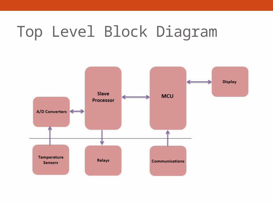
Top Level Block Diagram

ANALOG SUBSYSTEM

Sensor & Reading Specifications• Must be accurate within +/- 0.1 C• Read a minimum of:
• 2 differential thermocouple signals• 5 RTD signals
• Convert to digital signal and send to PIC• All noise/drift must be accounted for

Sensor TypesThermocouples
• Type S• 20 C min⁰• 1300 C max⁰• 0.1107 mV to 13.17 mV• Cavity source
• Type T• -30 C min⁰• 400 C max⁰• -1.21 mV to 20.87 mV• Extended area source
RTDs• PT100
• -30 C min⁰• 400 C max⁰• Extended area source:
• 88.22 Ω to 247.09 Ω• Cold junction comp:
• 100 Ω to 123.24 Ω

Block Diagram

Thermocouple Readings• Output range of -1.21 mV to 20.87 mV• Differential reading• Amplify signal to match min input requirements of AD
converter

Differential Op Amp
• Unity gain• VOCM = 2.5 V reference voltage
• Internal precision 10kΩ resistors


RTD Readings
• RTD ladder• Requires only 1 precision resistor
• Must match min input requirements of AD converter
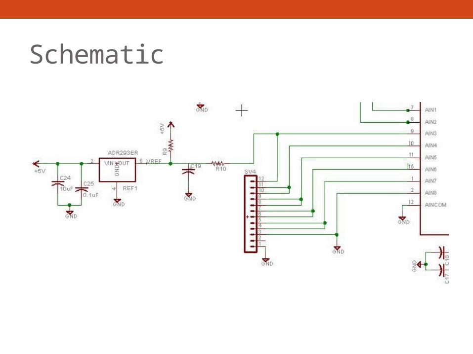
Schematic

A-D ConvertersAD7797
• 24 bit resolution• 1 differential input• SPI interface • Internal gain amplifier
fixed at 128• Used for heater (TC)
reading
AD7718• 24 bit resolution• 8 channel input MUX• SPI interface• Internal PGA of 1 or 128• Used for all RTD readings
and secondary TC reading

Reference Voltage ConsiderationsComponent Current DrawAD7797 1 μA
AD7718 1.25 μA
AD8476 – Op Amp (2) 5 μA
RTD Ladder 713 μA
TOTAL 720.25 μA
Vout = 2.5 VIout = 40 mATemp drift = 3ppm/ C⁰

MICROCONTROLLER

Microcontroller Specifications• Capable of Communicating with 8 Peripheral Devices.• Capable of Handling RS-232, RS-485, USB, and Ethernet
Protocols.• Capable of performing signed, floating point math.

PIC32MX150F128B• 2 SPI Lines• 2 UART Lines• Full-featured ANSI-Compliant C

General Design• Two PIC32MX150F128B connected in Master-Slave
configuration.• Slaves will be customized to serve a single purpose.• Master will handle outside communication and slave
coordination.

Pinout Table

Peripherals (from the Master)• MAX232 – RS232 - UART• MAX481 – RS485 - UART• MCP2200 – USB - UART• ENC28J60 – Ethernet – SPI• µLCD-32032 – Display – UART• PIC32MX150F128B – Slave – SPI

Peripheral Interfacing (Software)• No Interrupt Driven Pins
• Polling Transmit/Receive Buffers• Custom LABVIEW software to handle all interfacing• MAX232/MAX481 – No TX/RX Buffer• MCP2200 – 128 Bytes TX/RX Buffer• ENC28J60 – 8 KBytes TX/RX Buffer
Development Environment• MPLABX using MPLAB C32• Simulation Capability• Debugging
• Using PICKIT3

DISPLAY

Requirements• Touch Screen• Low-Cost• Fit in existing chassis• Interface easily to microcontroller

4D-Systems uLCD32 (GFX)
Deliver a diverse range of features in a single, compact, cost effective unit
• Built in Graphics Controller• Easy 5-pin interface • On-board Audio• Micro-SD card connector• Expansion Ports• Built in Graphics Libraries

Features
2
3
4
5 6
1
1.480x272 Resolution with 65k True to Life Colors
2.Expansion Ports (2)3.5 Pin Serial
Programming Interface4.PICASO-GFX2
Processor5.Micro-SD Card Slot6.1.2W Audio Amplifier
with Speaker
3.2”

Hardware Interface• Easy 5 pin
interface• Vin, TX, RX,
GND, RESET• Also used to
program display with 4D Programming Cable

PICASO-GFX2 Processor• Custom Graphics Controller• All functionality, including the high level
commands are built into the chip• Configuration available as a PmmC
(Personality-module-micro-Code)• PmmC file contains all low level micro-code
information• Provides an extremely flexible method of
customization

Audio/Micro-SD Card• Audio support is supplied by
the PICASO-GFX2 processor, an onboard audio amplifier and 8-ohm speaker
• Executed by a simple instruction
• Micro-SD card is used for all mulitmedia file retrieval such as images, animations and movie clips
• Can also be used as general purpose storage for data logging applications

Software Tools
1. 4D Workshop IDE
2. PmmC Loader
3. Graphics Composer
4. FONT Tool

• Temperature displayed at all times• User/Administrator Menu

POWER

Power Part
Current (mA) Voltage (V) Quantity Power (mW)
ADC 0.65 5 1 3.25
ADC 0.325 5 1 1.625
OpAmp 0.33 5 2 3.3
Ref 0.8 5 1 4
Quad Buffer 30 5 1 150
RS485 0.9 5 1 4.5
RS232 15 5 1 75
USB 95 5 1 475Ethernet Controller 180 3.3 1 594
Display 150 5 1 750Microcontroller
50 3.3 2 330
4:1 MUX 75 3.3 1 247.5
TOTALS 648.335 2638.175

Power Block Diagram
LS25-5 90 – 240 Vac
5V
ADC RS485OpAmp RS232Ref. DisplayBuffer USB
LT1129-3.3
EthernetMicrocontroller4:1 MUX
3.3V

PID

PID Requirements• Eliminate noise• Minimize overshoot• More efficient than standard PID

Nested PID• Initial loop encompasses
entire temperature range using only P and D parameters
• Next loop focuses on a smaller range and uses P, I and D
• Through testing we will determine the optimum repetition of these loops

COMPUTER USER INTERFACE

Requirements• Read data from the device• Ability to view PID values• Legible and convenient display

MagJack• Works with ENC28J60• RJ45 with built in masgnetics• Dual LEDs to inform of network activity

User Interface• Using NetBeans• Java based IDE (Intergrated Development Environment) • Good WYSIWYG Editor

Work Breakdown
Ashley Martin Cara Stacy
Analog Hardware 95% 5% - -
Digital Hardware - 80% - 20%
Display - 5% 95% -
Software 5% 10% 5% 80%Power - - 100% -

Progress
Resea
rch
Part S
electi
on
Program
ming
Design
Testin
g0%
10%20%30%40%50%60%70%80%90%
100%
IncompleteComplete

Potential Problems• Prototyping 24-SOIC parts• PID overshoot• Non-ideal operation of parts• Screen size

Budget
PartsDigital Devices $ 192
Display $ 101
Analog Devices $ 30
Prototyping Tools $ 25
Power $ 18
TOTAL $ 366
Goal: $500

QUESTIONS?