Embed Size (px)
Citation preview
Progress In Electromagnetics Research, PIER 92, 235–253, 2009
HIGH-ORDER ELECTROMAGNETIC MODELING OFSHORTWAVE INDUCTIVE DIATHERMY EFFECTS
M. Parise and S. Cristina
University Campus Bio-Medico of RomeVia Alvaro del Portillo 21, Rome 00128, Italy
Abstract—A high-order closed-form solution for the specific absorp-tion rate (SAR) distribution induced inside a plane geometry fatmuscletissue by a shortwave diathermy induction coil is presented. The solu-tion is derived starting from the complete integral expressions for theelectromagnetic field components generated by a currentcarrying cir-cular loop located horizontally above a stratified earth. It is valid in awide frequency range, and is flexible to any multi-turn coil configura-tion. The spatial distribution of the SAR induced in the muscle tissueby a flat round coil is computed by using the proposed formulation,the zero-order quasi-static one, and the finite difference time domain(FDTD) method. Excellent agreement is demonstrated to exist be-tween the results provided by the new approach and those achievedthrough FDTD simulations. On the contrary, the performed compu-tations show that the zero-order solution leads to over-estimate theSAR. The performances of the round and figure-eight coil geometriesare compared. Despite of what has been argued in previously pub-lished papers, it turns out that the figure-eight coil is less energeticallyefficient than the round one. The work in the present paper is anextension of a previous work.
1. INTRODUCTION
Shortwave or Radio Frequency (RF) inductive diathermy therapyconsists of using an applicator coil fed by a radiofrequency generatorto produce electric currents and ohmic heating in subcutaneous fatand muscle tissues by electromagnetic induction. This widespreadelectrotherapy treatment modality is employed for multiple purposes,that is to accelerate wound healing and nerve regeneration, to deal with
Corresponding author: M. Parise ([email protected]).
236 Parise and Cristina
vascular occlusion, and to reduce post-surgery pain or relieve musclespasms [1–3]. In particular, recent studies about wound healing [1]proved that the application of shortwave diathermy enhances theproliferation rates of the fibroblast cells, which are involved in thesynthesis of collagen and contribute to repair scar tissues. Previously,several tests performed on patients with peripheral vascular desease(PVD) [2] pointed out how the production of heating in deep tissuescauses vasodilation of the local vessels, thus increasing the blood flow.Moreover, heat produced by applicator coils is used in combinationwith conventional radiotherapy and chemotherapy for the managementof tumors (loco-regional hyperthermia [4–8]).
Regardless of the therapeutic purpose, diathermy treatmentplanning necessitates the a priori knowledge of the Specific AbsorptionRate (SAR) patterns induced in human tissues by coils.
When, as frequently occurs, the illuminated structure is humanback or abdomen, the SAR can be computed assuming a planartissue geometry, provided both the coil-to-subject spacing and coilradius are small if compared to the characteristic dimension ofthe cross section of the body trunk [3, 9, 10]. The EM analysiscan then be efficiently performed through analytical techniques,which require computer resources and computation times significantlysmaller than those implied by numerical procedures, and aresuitable for the comparative evaluation of various exposure conditionsand coil configurations. Closed-form expressions for the heatingpatterns generated in simplified tissue models (semi-infinite plane andcylinder) by circular coils were derived under the quasi-static fieldassumption [3, 10–13], that is neglecting the high-frequency effects dueto the displacement current (in both the air and the tissue) and thedepth of penetration (in the tissue). Yet, at the most commonly useddiathermy frequencies of 27.12 MHz or 40.68 MHz, any quasi-static(i.e., zero-order) model fails because the depth of penetration in muscletissue is smaller than the thickness of the layer, and more complexformulations are required in order to achieve accurate results.
The aim of this paper is to present a refined high-order model ofthe planar fat-muscle tissue combination exposed to radio waves froma diathermy coil, that responds to the following two requirements.First, it must be valid in the quasi-static as well as the nonquasi-static frequency regions (i.e., up to the maximum diathermy operatingfrequency). Second, it has to allow the analytical close-formulationfor the SAR distribution generated by any feasible flat multi-turngeometry. The latter requirement ensures minimum time consumptionwhen it is required to optimize the coil to produce a desiredheating pattern. The proposed model is based on the exact integral
Progress In Electromagnetics Research, PIER 92, 2009 237
representation for the electric field produced by a circular turn placedabove a stratified medium [14]. At first, such field integral is cast into aform suitable for the application of the Cauchy’s residue theorem. Nextthe non-oscillating part of the integrand is accurately approximatedwith a rational function according to the fitting algorithm [15],and finally the residue theorem is applied providing a closed-formexpression for the radial distribution of the electric field at anyplane parallel to the air-tissue boundary. The process of integrationtakes only few seconds, since the computational effort is limited tothe extraction of the poles and residues that describe the rationalapproximation. The heating patterns produced by multi-turn coils arecomputed by superposing the contributions arising from the differentturns. Moreover, since the function to be approximated is unique forall the possible turns at a given height from the medium, a singlerun of the fitting algorithm is enough to achieve the performancesof an infinite number of flat coils of various shapes and sizes. Thisfeature brings down the computational cost of any iterative processaimed at optimizing the coil geometry, and makes the proposed modeland computation methodology advantageous over standard purelynumerical techniques used to solve electromagnetic boundary valueproblems, like the FDTD and finite element methods.
The SAR distribution produced by the round coil in the regionoccupied by muscle tissue is computed by applying the proposedapproach. The obtained results closely agree with the correspondingones provided by FDTD simulations, while match the data achievedwith the quasi-static formulation only in the low frequency range. Athigher frequencies (like the diathermy operating frequencies) the quasi-static model leads to over-estimate the maximum SAR up to about30%.
Furthermore, to illustrate the flexibility of the developed methodto deal with different coil configurations, the poles and residues thathave been obtained for the case of a round coil are also used toinvestigate the heating pattern of a figure-eight (or butterfly) geometrymade up of a coplanar pair of coils with their perimeters touching. It isconfirmed that this configuration produces, with respect to the singleround coil, a more focused field under the joint, as was also concludedin previous papers [10, 11]. What has not yet been pointed out, andinstead emerges from the present analysis, is that, surprisingly, usinga figure-eight applicator worsens the efficiency of the system.
The present article is an extension of a previous conferencepaper [16]. It exhibits a more elegant and simplified theoreticaldevelopment, which allows to reduce from two to one the numberof rational approximations to be calculated. As a result, the
238 Parise and Cristina
computational time is halved as well. Furthermore, unlike thepreceding formulation, the solution proposed here can be easilyadjusted to any coil shape. Finally, a large number of numerical resultsare presented and investigated in this extended version.
2. THEORY
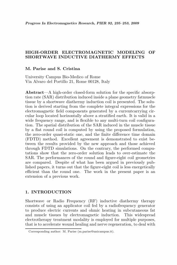
Consider a single-turn circular coil carrying a time-varying currentplaced horizontally above a planar skin-fat-muscle tissue combination,as shown in Fig. 1. The geometric configuration is symmetric withrespect to the coil axis, and a cylindrical coordinate system (r, ϕ, z) issuitably introduced and fixed on the skin surface.
a
hI
rz
o
d
skin
fat
muscle
z0
z1
μ , ε0 0
μ , ε , σ , ρ0 1 1 1
μ , ε , σ , ρ0 2 2 2
ϕ
Figure 1. Geometry and coordinates for a skin-fat-muscle planartissue exposed to a diathermy induction circular loop.
The thickness of the region occupied by the skin is negligible ifcompared to those of fat and muscle layers, to the local wavelengthand plane wave depth of penetration, and the EM field arising fromthe corresponding induced currents can be ignored. The thickness ofthe fat layer is d, while the muscle tissue can be considered a semi-infinite medium as long as its thickness is greater than the depthof penetration. The dielectric permittivity, electric conductivity, andmass density are respectively ε1, σ1, and ρ1 for fat, ε2, σ2, and ρ2 formuscle. The combination is assumed to have the magnetic permeabilityof free space μ0. The coil, with radius a, is situated in free space atheight h from air-tissue interface, and carries a current equal to Iejωt.Because of symmetry about the z-axis, the electric field generated bythe loop has no vertical component, and the EM field is transverseelectric (TE). The time-harmonic factor ejωt is suppressed throughoutanalysis. The exact integral representation for the nonzero electric field
Progress In Electromagnetics Research, PIER 92, 2009 239
component induced in the tissue is given by [14]:
Eϕ(r, z) =2Ia
π
∫ ∞
0f(λ, z)J1(λa)J1(λr)λdλ, (1)
with
f(λ, z) =
{g(λ)
[e−u1(z−d) + RTE
1 eu1(z−d)], 0 < z < d,
g(λ)(1 + RTE
1
)e−u2(z−d), z > d,
(2)
g(λ) =πωμ0(1 + RTE
0 )e−u0h
4ju0
(eu1d + RTE
1 e−u1d) , (3)
and being
um =(λ2 − ω2μmεm + jωμmσm
) 12 , (4)
RTE0 =
u0 [u1 + u2 tanh (u1d)] − u1 [u2 + u1 tanh (u1d)]u0 [u1 + u2 tanh (u1d)] + u1 [u2 + u1 tanh (u1d)]
, (5)
RTE1 =
u1 − u2
u1 + u2, (6)
respectively, the propagation coefficient in the m-th layer and thetransverse electric plane wave reflection coefficients at z = 0 and z = d.
The integral on the right-hand side of (1) is a first-order Hankeltransform. In principle, digital linear filter technique [17, 18] basedon exponential sampling would be suitable for the evaluation of thistransform, as the kernel function is seen to decay exponentially whenthe absolute value of λ increases. Yet, it is known that the conventionalapproach to digital filter design relies on repeated usage of the sampledomain Wiener-Hopf least-squares method within an optimizationloop [18]. Since the computational cost of the Wiener-Hopf method isproportional to the square of the filter length, such multiple executionscan take a huge amount of time for very long filter designs [17]. Thus,the accuracy of the result of computation can be theoretically enhancedby increasing the filter length, but at the cost of running an expensiveoptimization process. Furthermore, any digital filter is optimized for aspecific known integral transform (the so-called test function), and maylead to uncertain results when applied to the calculation of differenttransforms.
In order to overcome the intrinsic limitations of the digital filtertechnique, a new method is proposed for carrying out the evaluationof the integral on the right-hand side of (1). The key feature of themethod is that integration is performed analytically by applying the
240 Parise and Cristina
Cauchy’s residue theorem, once the function (2) is replaced with anaccurate rational approximation. At first the integral is cast into a formin which the range of integration extends from −∞ to ∞. Proceedingas discussed in [19] allows to derive the following representation forEϕ(r, z) alternative to (1):
Eϕ(r, z) =Ia
π
∫C1
f (λ, z) q(λ, r)λdλ (7)
with
q (λ, r) =
{H
(1)1 (λa)J1(λr), r < a,
J1(λa)H(1)1 (λr), r > a,
(8)
and being H(1)1 (ξ) the first-order Hankel function of the first kind.
The contour of integration C1 extends along the upper shore of thenegative real λ-axis (the branch cut of the Hankel function H
(1)1 ) and
the positive real λ-axis on the complex λ-plane, as shown in Fig. 2.It should be noted that, when increasing |λ|, the function f(λ, z)rapidly decay in all the quadrants of the complex λ-plane, while thefunction q (λ, r) exponentially diverges or decays depending on whetherIm[λ]<0 or Im[λ]>0. Hence, in agreement with Jordan’s lemma [20],Equation (7) does not suffer any alteration when closing the contour C1
with an infinite semicircle about the upper-half of the complex λ-plane.It reads:
Eϕ(r, z) =Ia
π
∫C1+C2
f (λ, z) q(λ, r)λdλ, (9)
being C2 the semicircle at infinity (a dashed line in Fig. 2).As proved in [20], any integral along a closed path C can be
evaluated by means of the residue theorem, provided the integrandis analytic inside and on C except for a number of pole singularities.In the present case, the square-root terms (4) introduce branch pointsingularities all over the complex λ-plane, which prevent from applyingthe residue theorem. To eliminate such branch points, the rationalapproximation
f (λ, z) ∼=Np∑n=1
cn(z)jλ2 − pn(z)
, (10)
is determined via the least squares-based fitting algorithm describedin [15]. The coefficients pn and cn (n = 1, . . . , Np) are either real orcome in complex conjugate pairs. Moreover, the pn’s are chosen sothat Re[pn]<0, and as a consequence the contour C1 + C2 encloses the

Progress In Electromagnetics Research, PIER 92, 2009 241
Im λ
λ−plane
C2
λ2
λ3λ1
λn
ε 0C1 Re λ
Branch cut of the Hankel functions
Figure 2. Closed path for the application of the residue theorem.
pole singularities λn =√−jpn (n = 1, . . . , Np). Substitution of (10)
into (9) and use of the residue theorem [20] lead to:
Eϕ (r, z) = 2jIa
Np∑n=1
�λn [bn(λ, r, z)] , (11)
withbn(λ, r, z) =
cn(z)jλ2 − pn(z)
q (λ, r) λ, (12)
and where
�λn [bn(λ, r, z)] = limλ→λn
[(λ − λn) bn(λ, r, z)] =12j
cn(z) q [λn(z), r]
(13)is the residue of bn(λ, r, z) at λ = λn.
Finally, substituting (13) into (11) yields:
Eϕ(r, z, h) = Ia
Np∑n=1
cn(z, h) q [λn(z, h), r, a] , (14)
where the dependences of the coefficients cn and λn upon h and thatof q upon the loop radius a are made explicit. Computational effortsof the proposed methodology are limited to the calculation of the cn’sand λn’s, and the accuracy of the results depends only on the quality of

242 Parise and Cristina
fitting. No expensive sample-domain optimization process is required,since the integral in (9) is solved analytically.
Closed-form expressions for the electric field distributions inducedin tissues by multi-turn coils can be derived by superposing solutionsof the form (14) valid for the separate turns. Coplanar turns sharethe same set of poles and residues and, as a consequence, electric fielddistributions arising from flat coils are computed with minimum timeconsumption. This is the case, for instance, of the pancake-shaped coilmade up of N concentric turns having different radii varying from a1
(inner radius) to aN (outer radius). Summing up the contributions (14)from all the turns of the coil leads to
E(pc)ϕ (r, z, h) = I
N∑i=1
ai
Np∑n=1
cn(z, h) q [λn(z, h), r, ai ] . (15)
Analogous expressions can be obtained for coils constituted bynon-concentric turns. In these cases, the summation of the variouscontributions is performed after splitting the electric field vectorgenerated by the i-th turn into its cartesian components along thex and y axes belonging to the coil plane (Fig. 3). From (14), it followsthat:
Exi(x, y, z, h) = −Iiai(y − yi)ri
Np∑n=1
cn(z, h) q [λn(z, h), ri, ai] , (16)
Eyi(x, y, z, h) =Iiai(x − xi)
ri
Np∑n=1
cn(z, h) q [λn(z, h), ri, ai] , (17)
where Pi ≡ (xi, yi) is the center of the i-th turn, and ri =√(x − xi)2 + (y − yi)2. The total electric field components are
expressed as:
Ex(x, y, z, h) =N∑
i=1
Exi(x, y, z, h), (18)
Ey(x, y, z, h) =N∑
i=1
Eyi(x, y, z, h), (19)
Notice that all the feasible flat coil geometries placed at heighth above the tissue correspond to a unique set of poles and residues.This feature is particularly useful when it is necessary to search forthe optimum coil that produces a desired field pattern, since the

Progress In Electromagnetics Research, PIER 92, 2009 243
x
i
iI r i
P
y i
E
a i
o
xi
y i
ixE
iyE
ϕ
ϕ
Figure 3. Geometry for the i-th turn.
conventional approach for solving such inverse problem relies on thecomputation of the patterns associated to coils of various shapes andsizes within an optimization loop. As the cn’s and λn’s are calculatedbefore entering the optimization algorithm, the computational workthat remains to be done at each iteration is negligible. This alonemakes the proposed methodology advantageous over purely numericaltechniques like the finite difference time domain and finite elementmethods.
3. RESULTS AND DISCUSSION
3.1. Validation of the Method
Since therapeutic heating is required in deeper regions of human body,the developed theory is applied to the computation of the SAR inducedin the muscle tissue sketched in Fig. 1 by a pancake round-shaped coil,which represents a widely used applicator for diathermy. The SAR(W/kg) in the muscle tissue is expressed as:
SAR(r, z) =σ2E
2ϕ(r, z)ρ2
, z > d, (20)

244 Parise and Cristina
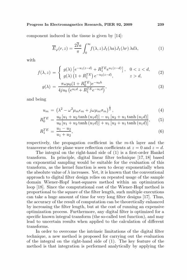
where Eϕ(r, z) is given by (15). The calculations are performedassuming σ1 = 0.033 S/m, εr1 = 8.45, ρ1 = 0.96 g/cm3, σ2 = 0.71 S/m,εr2 = 91.6, and ρ2 = 1.02 g/cm3 [21]. The coil has four compactlywound turns, inner radius a1 = 5.4 cm and outer radius a4 = 6cm.The wire, 0.2 cm in diameter, carries a current of 1A. The coil-to-subject spacing and fat layer thickness are respectively h = 3.5 cmand d = 2.25 cm. At first, the distribution of the SAR is evaluatedat depth z′ = z − d = 3.5 cm below the fat-muscle interface and atthe frequency of 27.12 MHz. The obtained results, depicted in Figs. 4and 5, show that the maximum of the deposited power is not on theaxis of symmetry of the coil and is not restricted to a small region, butit is spread circularly under the edge of the coil.
-20-10
010
2020
10
0
-10
-20
0
0.1
0.2
0.3
0.4
0.5
SA
R (
W/k
g)
0.40.30.20.1
x (cm)
y (cm)
Figure 4. 3D view of the SAR distribution induced by the round coilin the muscle tissue 3.5 cm below the fat-muscle interface.
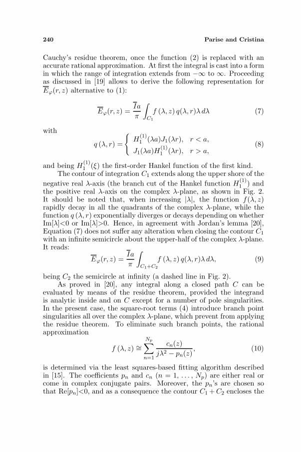
Figure 5 also illustrates the comparison among the SAR valuesobtained by applying (15) and those provided by the zero-orderquasistatic model [10–13] and the FDTD method. Results achievedwith the proposed high-order solution agree well with the FDTD data.On the contrary, the plotted curves demonstrate how the quasi-staticassumption leads to overestimating the EM energy absorption, andthis is a consequence of ignoring the attenuation of the electric fieldstrength due to the depth of penetration. The absolute error generatedby the zero-order model increases with the radial distance from the coilaxis, up to the maximum value of 78 mW/kg at r ∼= 12 cm (Fig. 6).Thereinafter, the absolute error diminishes indefinitely.
As far as the relative error is concerned, it increases as the radialdistance increases, with values comprised between 10% and 50% in therange r = 3–17 cm, where heating is at least one-third the peak value.
Progress In Electromagnetics Research, PIER 92, 2009 245
0
0.1
0.2
0.3
0.4
0.5
0 5 10 15 20 25 30 35
SA
R (
W/k
g)
Radial distance (cm)
High-order
Zero-order
FDTD
Figure 5. Radial distribution of the SAR induced by the round coilin the muscle tissue 3.5 cm below the fat-muscle interface.
0
10
20
30
40
50
60
70
80
90
2 4 6 8 10 12 14 16 18 20
% E
rror
, E
rror
(m
W/k
g)
Radial distance (cm)
% Error
Abs. Error
Figure 6. Radial distribution of the relative and absolute errorsresulting from the SAR calculated by applying the zero-order approach.
For r > 17 cm, the relative error is greater than 50%, but has littlerelevance because of the poor heating.
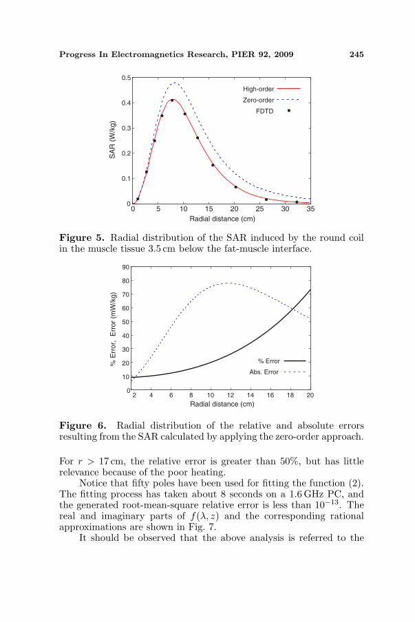
Notice that fifty poles have been used for fitting the function (2).The fitting process has taken about 8 seconds on a 1.6 GHz PC, andthe generated root-mean-square relative error is less than 10−13. Thereal and imaginary parts of f(λ, z) and the corresponding rationalapproximations are shown in Fig. 7.
It should be observed that the above analysis is referred to the
246 Parise and Cristina
-3
-3
-3
-3
-3
-3
-3
-30 -20 -10 0 10 20 30
f (λ
, 3.
5 1
0
).
−2
Im [f (λ, 3.5 10 )]. −2
Re [f (λ, 3.5 10 )]. −2
Lambda, λ [m ]−1
7.10
5.10
3.10
1.10
-1.10
-3.10
-5.10
Figure 7. Real and imaginary parts of the function f(λ, z) versus λ.Exact (−) and rational approximation (•).
0
5
10
15
20
25
30
0 5 10 15 20 25 30 35 40
% E
rror
Frequency (MHz)
z'=2 cm
z'=3.5 cm
z'=5 cm
Figure 8. Relative percent error resulting from computing the peakheating by applying the zero-order model against frequency.
particular operating frequency of 27.12 MHz, and to the depth ofz′ = 3.5 cm from the muscle layer upper boundary.
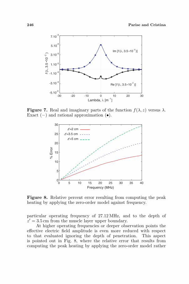
At higher operating frequencies or deeper observation points theeffective electric field amplitude is even more reduced with respectto that evaluated ignoring the depth of penetration. This aspectis pointed out in Fig. 8, where the relative error that results fromcomputing the peak heating by applying the zero-order model rather

Progress In Electromagnetics Research, PIER 92, 2009 247
than the proposed one is plotted against frequency. The plotted curvesshow that at the frequency of 1 MHz and lower the relative errorproduced by the zero-order model is almost null for every depth z′of the observation point in the muscle tissue. In fact, at 1 MHz thevalues of depth of penetration in fat and muscle are large if comparedrespectively to the thickness of the fat layer and the depth of theobservation point from the muscle upper boundary, and the total andthe incident electric fields are substantially coincident. Thereinafter,the relative percent error grows up with increasing frequency and, forthe same frequency, higher errors are generated at deeper locations. At40.68 MHz and for z′ ≥ 5 cm the relative percent error exceeds 30%.
3.2. Figure-eight Geometry
As a special case of multiple-coil configuration, the figure-eight orbutterfly-shaped coil is considered in this paragraph. This geometryconsists of a coplanar pair of oppositely connected round coils (seeFig. 9), and produces a localization of the deposited power under thepoint of intersection, where the eddy current densities induced by thetwo coils are additive.
The SAR deposited in the muscle tissue is expressed as:
SAR =σ2
(E2
x + E2y
)ρ2
, (21)
where Ex and Ey are given by (18) and (19). The SAR is computed
'
I
r r'
P
y
x
E
E
a1
a2
a3
a4 a5
a6
I
ϕ ϕ
'ϕ
ϕ
Figure 9. Geometry and coordinates for a figure-eight coil.

248 Parise and Cristina
at depth z′ = 3.5 cm from the fat-muscle boundary, assuming thatthe coil has six turns, with a1 = a4 = 2 cm, a2 = a5 = 2.2 cm,and a3 = a6 = 2.4 cm, and carries a current I = 3A at 27.12 MHz.Notice that the electric field components (18) and (19) are calculatedby using the same set of poles and residues found for the single roundcoil. Numerical results are shown in Figs. 10 and 11, which present,respectively, a 3D view and the profile along the x-axis of the absorbed
-15 -10 -5 0 5 10 15 15
105
0-5
-10-15
0
20
40
60
80
100
SA
R (
mW
/kg)
9070352015107654
x (cm)
y (cm)
Figure 10. 3D view of the SAR distribution induced by the butterflycoil in the muscle tissue 3.5 cm below the fat-muscle interface.
0
10
20
30
40
50
60
70
80
90
100
110
-30 -20 -10 0 10 20 30
SA
R (
mW
/kg)
x (cm)
Round
Γ= 2
Γ=1.4
Γ=1
Γ=0.5
Figure 11. Computed SAR profiles along the x-axis. Round (solidline) and butterfly (dashed lines) coils.

Progress In Electromagnetics Research, PIER 92, 2009 249
power density.Figure 11 illustrates the SAR profiles arising from both the
butterfly coil (upper dashed line) and its left wing alone centered atthe origin of the x-y plane (solid line). From the comparison betweenthese two curves it turns out that closing together two round N -turncoils to form a butterfly geometry increases the peak heating. Thisis made at the cost of doubling the required Joulean and magneticfield energies. In fact, if the total resistance and self-inductance are,respectively, RB and LB for the butterfly coil with 2N turns, RW andLW for the single wing with N turns, it results [11]:
RB(2N) = 2RW (N), LB(2N) ∼= 2LW (N), (22)
and, consequently,
PB(2N, I) = RB(2N)I2 = 2RW (N)I2 = 2PW (N, I), (23)UB(2N, I) = LB(2N)I2 ∼= 2LW (N)I2 = 2UW (N, I), (24)
where P = RI2 is the average power dissipated by R, and U = LI2
is the energy in the magnetic field when the current in the coil ismaximum (Imax = I
√2). In order to discern whether the butterfly
coil is more efficient than the single wing or not, comparison should bemade between the heating patterns generated from the same amountof energy. For this purpose, the values 2N ′ and I ′ for the number ofturns and the current in the butterfly coil are determined that makethe required active power PB(2N ′, I ′) and magnetic energy UB(2N ′, I ′)equal respectively to PW (N, I) and UW (N, I). The system of equationsto be solved is the following
2RW (N ′)I ′2 = RW (N)I2, (25)
2LW (N ′)I ′2 = LW (N)I2, (26)
and can be further reduced to one equation by introducing the well-known expressions for the resistance and self-inductance of a roundcoil [11]
RW (N) = αRN2, LW (N) = αLN2, (27)
where αR and αL depend on geometrical factors (i.e., the inner andouter radii). It yields:
2N ′2I ′2 = N2I2, (28)
that is, for fixed N and I, the equation of an equilateral hyperbola.Notice that the function
Γ(N ′, I ′) =PB(2N ′, I ′)PW (N, I)
=UB(2N ′, I ′)UW (N, I)
= 2(
N ′I ′
NI
)2
, (29)
250 Parise and Cristina
which represents the normalized dissipated power as well as thenormalized maximum magnetic energy in the butterfly coil, isconstantly equal to unity when moving along such hyperbola. Hence,Equation (28) describes a level curve (contour line) of Γ.
It can be numerically verified that all the points (N ′, I ′) belongingto a contour line (hyperbola) of Γ lead to the same heating pattern.For instance, the SAR profile of Fig. 11 corresponding to Γ = 2 isobtained either assuming (N ′, I ′) = (N, I) = (3, 3A), as it has beenmade, or for any other choice of N ′ and I ′ such that N ′I ′ = NI = 9A.
From the analysis of the curve labeled with Γ = 1 it can beconcluded that, when the provided energy is the same for the twoconfigurations, the peak heating produced by the butterfly coil is aboutone-fourth lower than that generated by the round one. Furthermore,contrarily to what has been argued in previous works [10, 11], thecurve indicated with Γ = 1.4 demonstrates that both the Joulean andmagnetic energies required to induce a given SAR intensity with a two-coil geometry are larger (by 40 percent) than and not about half thoserequired with a single round coil of the same inner and outer radii aseach of the two coils.
In fact, for Γ = 0.5 (that is for N ′ = N = 3 and I ′ = I/2 =1.5 A), the maximum power density deposited by the butterfly coilis 23.5 mW/kg. The round coil provides this value of SAR, which issignificantly less than the maximum, at radial distance r = 2.4 cm fromthe axis, that is at a point approximately under the coil edge (locatedat r = 2.6 cm). It is true that, after halving the energy supply, theSAR calculated under the edge of a round coil does not change if it isjoined to another coil with identical dimensions. At the same time, it isalso true that the peak SAR diminishes by a factor of 3 (see Fig. 11).Despite of increasing electric field focality, the butterfly geometry isless energetically efficient than the single coil geometry. It has beenpointed out that the computational cost of the proposed approach issignificantly smaller than that implied by numerical techniques likethe FDTD method, whenever it is required to optimize the coil toproduce a prescribed heating pattern. However, this advantage mightbe lost if the coil geometries that are going to be considered withinthe optimization loop are not composed of circular turns. For suchmore complicated sources, the FDTD method is then a more flexibleand standardized technique. Finally, it should be observed that theenergetic efficiency as well as the degree of localization (i.e. thefocality) of diathermy treatment can be directly deduced from thespatial distribution of the power density deposited in the tissue. Thetemperature rise in the tumor or treated area, instead, cannot bequantified on the basis of the SAR alone, since it is heavily determined

Progress In Electromagnetics Research, PIER 92, 2009 251
by the blood flow in local vessels. In fact, the increase in blood flowdue to vasodilatation has a cooling effect. Even the effectiveness of thetreatment does not depend uniquely on the SAR distribution inducedby the coil, as it varies also according to the patient pain tolerance.
4. CONCLUSION
A method has been developed that allows to determine a high-orderclosed-form solution for the SAR distribution induced inside a fat-muscle tissue by a diathermy induction coil. The method has beenderived starting from the exact complete expressions for the EM fieldcomponents generated by a current-carrying circular loop placed abovea stratified earth. The integral expression describing the elementarycontribution of the generic turn of the coil to the total producedelectric field is integrated according to an exact procedure, once thenon-oscillating part of the integrand is replaced with an accuraterational approximation generated by a fitting algorithm. The processof integration takes only few seconds, since the computational effortis limited to the extraction of the poles and residues of the rationalapproximation. The obtained closed-form solution is valid in a widefrequency range, and is different from the commonly used zero-orderformulations that do not account for the attenuation of the electricfield magnitude in the tissue due to the depth of penetration.
In the case of flat multi-turn coils, the heating patterns inducedin tissues are computed by superposing the simple solutions valid forthe separate turns. Since the poles and residues to be determinedare the same for all the coplanar turns which constitute the coil, timeconsumption is minimum and is only weakly affected by the number ofturns and the shape of the coil. Furthermore, the poles and residuesobtained for a particular coil geometry can be used for analyzing theperformances of an infinite number of coplanar geometries, with clearadvantages in terms of computational cost. This alone makes theproposed methodology exceptionally useful when it is necessary tosearch for the optimum coil that produces a desired field pattern, andconvenient with respect to any purely numerical technique commonlyused to solve electromagnetic boundary value problems, like the FDTDor finite element methods. Spatial distributions of the SAR induced inmuscle tissue by round and figure-eight coils are computed by applyingthe developed method. The obtained results are in excellent agreementwith those provided by FDTD simulations. Conversely, the observeddisagreement with numerical data produced by the zero-order modelconfirms that the quasi-static expressions for the field components leadto overestimating the EM energy absorption, and this is a consequence
252 Parise and Cristina
of ignoring the high-frequency effects of the depth of penetration in thetissue. Finally, the investigation of the heating pattern of a figure-eightcoil has allowed to conclude that, surprisingly, such geometry is lessefficient than the round one, though doubtless capable of producing amore localized electromagnetic field.
REFERENCES
1. Hill, J., M. Lewis, P. Mills, and C. Kielty, “Pulsed short-wave diathermy effects on human fibroblast proliferation,”Arch. Phys. Med. Rehabil., Vol. 83, No. 6, 832–836, 2002.
2. Santoro, D., L. Ostrander, B. Y. Lee, and B. Cagir, “Inductive27.12 MHz diathermy in arterial peripheral vascular disease,”EMBS 1994, Proc. IEEE 16th Annual Intern. Conf., Vol. 2, 776–777, 1994.
3. Guy, A. W., J. F. Lehmann, and J. B. Stonebridge, “Therapeuticapplications of electromagnetic power,” Proceedings of the IEEE,Vol. 62, No. 1, 55–75, 1974.
4. Rhattoy, A., S. Bri, and M. Audhuy-Peudecedery, “Coaxialantenna for microwave hyperthermia,” Journal of ElectromagneticWaves and Applications, Vol. 19, No. 14, 1963–1971, 2005.
5. Rajhi, A., “Optimization of the EM heating cycle by usinga dual frequency local hyperthermia applicator,” Journal ofElectromagnetic Waves and Applications, Vol. 17, No. 3, 447–464,2003.
6. Wu, M. S., K. Ito, and H. F. Kasai, “Analysis of current andelectric field distributions of coaxial-slot antenna for interstitialmicrowave hyperthermia,” Journal of Electromagnetic Waves andApplications, Vol. 9, No. 5–6, 831–849, 1995.
7. Kerem, M. and K. Yigiter, “Effects of continuous and pulsedshortwave diathermy in low back pain,” The Pain Clinic, Vol. 14,No. 1, 55–59, 2002.
8. Sciuto, M. G., C. Zanon, A. Mussa, R. Clara, M. Bortolini,A. Malossi, R. Moscato, P. Celoria, M. De Andrea, M. Rizzo,and I. Chiappino, “Chemohyperthermia for advanced abdominalmalignancies: A new procedure with closed abdomen andpreviously performed anastomosis,” International Journal ofHyperthermia, Vol. 17, No. 5, 456–464, 2001.
9. Curto, S. and M. J. Ammann, “Electromagnetic couplingmechanism in a layered human tissue model as reference for434 MHz RF medical therapy applicators,” Proc. 2007 IEEE

Progress In Electromagnetics Research, PIER 92, 2009 253
Antennas and Propagation Society International Symposium,Vol. 1, 3185–3188, 2007.
10. Ren, C., P. P. Tarjan, and D. B. Popovic, “A novel electricdesign for electromagnetic stimulation — The slinky coil,” IEEETrans. Biomed. Eng., Vol. 42, No. 9, 918–925, 1995.
11. Nyenhuis, J. A., G. A. Mouchawar, J. D. Bourland, and L. A. Ged-des, “Energy considerations in the magnetic (Eddycurrent) stimu-lation of tissues,” IEEE Trans. Magnetics, Vol. 27, No. 1, 680–687,1991.
12. Esselle, K. P. and M. A. Stuchly, “Quasi-static electric field ina cylindrical volume conductor induced by external coils,” IEEETrans. Biomed. Eng., Vol. 41, No. 2, 151–158, 1994.
13. Schnabel, V. and J. J. Struijk, “Calculation of electric fields in amultiple cylindrical volume conductor induced by magnetic coils,”IEEE Trans. Biomed. Eng., Vol. 48, No. 1, 78–86, 2001.
14. Singh, N. P. and T. Mogi, “Electromagnetic response of a largecircular loop source on a layered earth: A new computationmethod,” Pure and Applied Geophysics, Vol. 162, No. 1, 181–200,2005.
15. Gustavsen, B. and A. Semlyen, “Rational approximation offrequency domain responses by vector fitting,” IEEE Trans. PowerDelivery, Vol. 14, No. 3, 1052–1061, 1999.
16. Cristina, S. and M. Parise, “Closed-form expression of theSAR distribution in a multilayered planar model for shortwaveinductive diathermy,” Proc. IEEE 1st Intern. Conf. Bio. MedicalEngineering & Informatics, Vol. 2, 577–582, 2008.
17. Guptasarma, D. and B. Singh, “New digital linear filters fo HankelJ0 and J1 transforms,” Geophysical Prospecting, Vol. 45, No. 5,745–762, 1997.
18. Kong, F. N., “Hankel transform filters for dipole antenna radiationin a conductive medium,” Geophysical Prospecting, Vol. 55, No. 1,83–89, 2007.
19. Felsen, L. B. and N. Marcuvitz, Radiation and Scattering ofWaves, IEEE Press, Piscataway, NJ, 1994.
20. Marsden, J. E. and M. J. Hoffman, Basic Complex Analysis,W. H. Freeman and Company, New York, 1998.
21. “Tissue dielectric properties,” Federal Communications Com-mission, Washington, DC [Online], http://www.fcc.gov/fcc-bin/dielec.sh.