Embed Size (px)
Citation preview
High-order approximation of wave propagation constants in a uniformly curved waveguide
I.V.Petrusenko
Abstract: New high-accuracy approximations of the angular propagation constants of LE,,,, and LM,,,, modes in a continuously curved rectangular waveguide are derived. They are high-order asymptotic expansions that are obtained using analytical computations. The formulas can be used for both propagating modes and an arbitrary number of evanescent ones. The approximations are applicable over a broad range of curvature variation and a wide range of wavenumber values. They are efficient tools for the numerical solution of modal equations.
1 Introduction
The propagation of electromagnetic waves in curved guide structures has been a subject of interest to researchers for many years because of its great practical importance [1-31. Rectangular waveguides and microstrips that are continu- ously curved in the H- or E- plane in a circular arc (so- called uniform bends of guides) and various devices constructed on their basis (wave transformers, power divid- ers, rotary antenna relays, etc.) are widely used in micro- wave engineering.
To date, most of the work has focused on analysis of the junctions of a straight waveguide and a curved section of the bend. Useful references to a portion of a large body of the work are given in [l-91. The problem has been treated by a variety of methods. Most of them were developed to obtain an effective modal solution in the curved region, which is the key problem in curved guide theory.
Approximate modal solutions were derived in [l] by means of perturbation analysis. This technique was applied to modelling of the curved microstrip bend in [4]. An origi- nal method of conversion of the initial eigenvalue problem into an equivalent matrix eigenvalue equation was devel- oped in [5]. The calculation of the radial mode function by means of a step-like approximation was applied in [6]. According to the method of local modes [7], the field in the bend is described by means of superposition of modes of the locally straight waveguide. Modal decomposition, which is based on a combination of the approaches from [1, 51, was used in [SI. A step-like approximation of the uni- form bend by elementary mitred bent waveguides was applied in [9]. In all these works, the transformations of the initial boundary value problem were developed to over- come the difficulties of eigenmode analysis for a guide bend.
0 LEE, 2001 IEE Proceedmgs online no. 20010646 DOL 10.1049/ipmap:20010646 Paper first received 16th May 2000 and in revised form 16th July 2001 The author is with the Gebze Institute of Technology, GYTE, Cayirova kam- pus, 41400 P.K. 141, GebzdKmeli, Turkey and is on leave from the Dniepro- petrovsk National University, Naukova lane, 13, Dniepropetrovsk-50,
320625
In this paper, attention is focused on the straightforward numerical-analytical solution of the initial eigenvalue prob- lem for a uniformly curved guide. The main objective is to derive high-precision approximations of the propagation constants for both the propagating modes and an arbitrary number of evanescent ones. The approximations serve as a basis for an effective numerical solution of the modal equa- tions.
The results obtained are meant not only for the bend problem but for the rigorous analysis of more complicated structures, such as stratified dielectric posts in a curved guide, the curved power dividers and T-junctions.
2 Problem specification
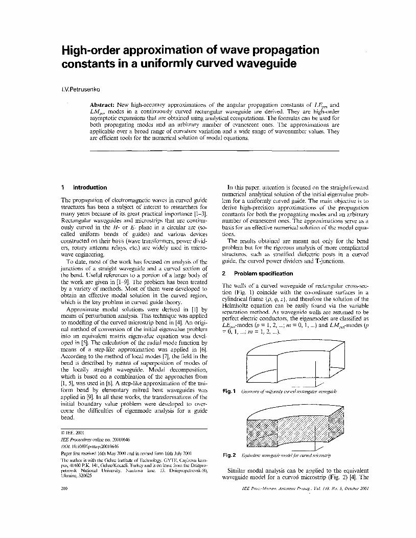
The walls of a curved waveguide of rectangular cross-sec- tion (Fig. 1) coincide with the co-ordinate surfaces in a cylindrical frame {p, 4, z } , and therefore the solution of the Helmholtz equation can be easily found via the variable separation method. As waveguide walls are assumed to be perfect electric conductors, the eigenmodes are classified as LE,,-modes (p = 1, 2, ...; m = 0, I , ...) and LM,,,,,-modes 07 -0 , l , . . . ; m = l , 2 ,... 1. -
-_y
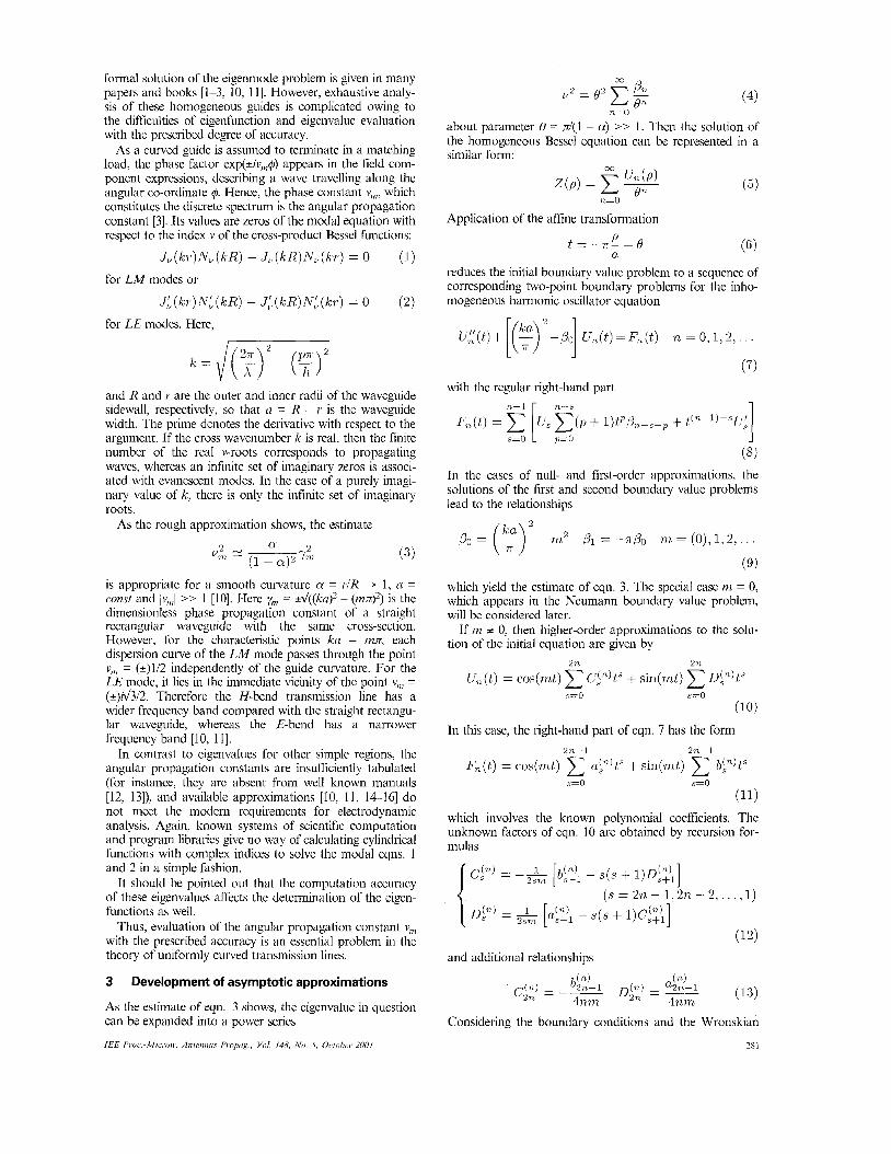
Fig. 2 Eqiriwlent wiveguide nrodd for curwd microstrip
Similar modal analysis can be applied to the equivalent waveguide model for a curved microstrip (Fig. 2) [4]. The
IEE Pruc - 1 ! 4 1 ~ r o ~ v AntennuJ Proprig Vol 148 N o S Ocfoher 2001 280
formal solution of the eigenmode problem is given in many papers and books [l-3, 10, 111. However, exhaustive analy- sis of these homogeneous guides is complicated owing to the difficulties of eigenfunction and eigenvalue evaluation with the prescribed degree of accuracy.
As a curved guide is assumed to teminate in a matching load, the phase factor exp(*iv&) appears in the field com- ponent expressions, describing a wave travelling along the angular co-ordinate q5. Hence, the phase constant vi,,, which constitutes the discrete spectrum is the angular propagation constant [3]. Its values are zeros of the modal equation with respect to the index v of the cross-product Bessel functions:
J,(lcr)N,(kR) - J,(kR)N,(kr) = 0
JL(kr)NL(kR) - J;(kR)N:(Fr) = 0
(1)
(2)
for LM modes or
for LE modes. Here,
and R and I' are the outer and inner radii of the waveguide sidewall, respectively, so that n = R - Y is the waveguide width. The prime denotes the derivative with respect to the argument. If the cross wavenumber k is real, then the finite number of the real v-roots corresponds to propagating waves, whereas an infinite set of imaginary zeros is associ- ated with evanescent modes. In the case of a purely imagi- nary value of k, there is only the infinite set of imaginary roots.
As the rough approximation shows, the estimate
(3)
is appropriate for a smooth curvature a = I'/R - 1, n = const and ~ v l , , ~ >> 1 [lo]. Here ym = d ( ( k ~ ) ~ - ( n z ~ ) ~ ) is the dimensionless phase propagation constant of a straight rectangular waveguide with the same cross-section. However, for the characteristic points ka = nzz, each dispersion curve of the LM mode passes through the point vi,, = (+)U2 independently of the guide curvature. For the LE mode, it lies in the inmediate vicinity of the point v,,, = (+)d3/2. Therefore the H-bend transmission line has a wider frequency band compared with the straight rectangu- lar waveguide, whereas the E-bend has a narrower frequency band [IO, 1 I].
In contrast to eigenvalues for other simple regions, the angular propagation constants are insufficiently tabulated (for instance, they are absent from well known manuals [12, 13]), and available approximations [IO, 11, 14-16] do not meet the modem requirements for electrodynamic analysis. Again, known systems of scientific computation and program libraries give no way of calculating cylindrical functions with complex indices to solve the modal eqns. 1 and 2 in a simple fashion.
It should be pointed out that the computation accuracy of these eigenvalues affects the determination of the eigen- functions as well.
Thus, evaluation of the angular propagation constant v,,, with the prescribed accuracy is an essential problem in the theory of uniformly curved transmission lines.
3 Development of asymptotic approximations
As the estimate of eqn. 3 shows, the eigenvalue in question can be expanded into a power series
IEE Proc.-Microw. Anteiiiim Proprig., Vol. 148. No. 5, October 2001
CO
(4) y2 = Pn On
n=O
about parameter 0 = d(l - w) >> 1. Then the solution of the homogeneous Bessel equation can be represented in a similar form:
(5) n=O
Application of the affine transformation
( 6 ) P a
t = - r r - + O
reduces the initial boundary value problem to a sequence of corresponding two-point boundary problems for the inho- mogeneous harmonic oscillator equation
(7) with the regular right-hand part
+ l)tq3,-,-, + ( 8 )
In the cases of null- and first-order approximations, the solutions of the first and second boundary value problems lead to the relationships
(9) which yield the estimate of eqn. 3. The special case nz = 0, which appears in the Neumann boundary value problem, will be considered later.
If m ;t 0, then higher-order approximations to the solu- tion of the initial equation are given by
2 n 211.
un(t) = cos(m,t) ~ i " ) t ' + sin(mt) obn)tS s=o s=o
(10)
In this case, the right-hand part of eqn. 7 has the form
s=o s=o
(11) which involves the known polynomial coefficients. The unknown factors of eqn. 10 are obtained by recursion for- mulas
and additional relationships
Considering the boundary conditions and the Wronskian
28 I
for cylindrical functions, we find
n > l
The final expressions for the required term of the asymp- totical series in eqn. 4 are of the form
(15) for the Dirichlet (upper row) and Neumann (lower row) boundary value problems.
It is well known that, in the case of the Neumann bound- ary value problem, a so-called null-root of the modal equa- tion appears that corresponds to the LEpo mode in the curved waveguide and to the TEM wave in the microstrip. In this case, eqn. 4 is of the form
3n--2
s=o
and the solution is obtained as a polynomial 3n
s=o
where cl@) = 0, n t I , as follows from the boundary condi- tions. Taking into account that
and c p ) = 0, n 2 1 , the final formula can be written in the form
1 3n
pn = -- ("ITs n 2 2 .ir2 scs
The algorithm developed and the formulas in eqns. 15 and 19 are suitable for realisation in the modem systems of computer algebra. The readily obtained terms Po and /3, are used as initial values for the analytical computation pro- gram. The terms f$ and = 0 obtained by hand were used as test solutions. The number of terms in the series in eqn. 4, which can be found using the above algorithm, is limited only by computer resources.
4 Analytical approximations of angular propagation constants
The asymptotic approximations derived made it possible to evaluate, not only all real v-zeros of the modal eqns. 1 and 2, but also the arbitrary number of purely imaginary ones for the evanescent modes. Adequate accuracy can be ensured if the high-order series terms are accounted for.
The formulas of a reasonable length are given below, where the following symbols are used
(19) s=3
r R a! = -, w = ("2
71 = 1 ~2 = 1 + (1 - C Y ) - (1 - a)3 + 3(1 -
7 3 = 1 + 2(1 - C Y ) - 5(1 - a!)3 + 28(1 74 = 1 + 3(1 - a ) - 14(1 - a!)3
- 17(1 - a)7
7 5 = 1 + 4(1 - C Y ) (20)
282
4. I Angular propagation constants of LM modes
2 U& = - 1 + (E-)
x ' { n=l
4 1-ar 4
a + CG$,, (1 - + 0 [( 1 - a ) l O y 9 ]
(21) where q = yn,21w = (ku/m..>2 - 1 8' = -l/(l2w)[q(o -15) - 181 8 4 = ll(720d)[q3(-5d + 105001 - 9900) + q2(-8d +
8 6 = l/(60480d)[q5(-105d + 86625d - 49140000 + 40162500) + $(-294d + 292950d - 172594800 + 142090200) + q3(440d + 448497d - 238291200 + 192092040) + q2(472d + 390348d - 161557200 +
(3024002 - 6804000 + 3606120)l 8 8 = 1/(36288000~)[q~(-22750~ + 477750003 -838593000d + 325883250000 - 244518750000) + q6(-896Om4 + 21403200d - 3912375600d + 1543691520000 - 1162953288000) + qS(-31072w4 + 53279700~2 - 8309952000d + 3080854980000 - 22821441 55200) + &58696u4 + 85177320d - l0420454520d + 335090800800~ - 2373499422000) + q3(44800w4 + 83706120d - 8125903800d + 213399635400~ - 1394503614000) + q2(4O320w4 + 48246480d - 3785223960d + 7866648720001 - 453675751200) + q(14878080d - 932510880d + 151770024000 - 73209679200) + (1 8 144OOd - 88905600d + 1 1240208000 - 4247737200)l.
4.2 Angular propagation constants of LE modes
2 4 0 0 ~ - 22860) + q(17100 - 16740) + (3600 - 3780)]
122109120) + q(178416d - 5352480~ + 35550900) +
4.2. I Case of null-root:
Y U; I= ~
(1 - a! )2
where q = (ka)2 /& = 1/30(q + 5) b4 = 11623700(-59q3 + 341q' + 825q - 3465) 8 6 = 1/248 1078600OO( 14263 14' - 1 106360$ - 2 1 054330q3 + 128290500q2 + 291537675q - 1214284500) bg = 1/1 127058486453900000(-4951757125q7 + 49568642809q6 + 1746871820100q5 - 4397782190000q" - 74924986531725q3 + 51 89503785320259' + 101 601 5125875750q - 41 395049348 15250) 6 1 0 = (0.376565730 x 0.238467143 x 0.185771175~ 10-sq5-0.187650960 x 10"&0.523248451 x lo4 q3 + 0.414286935 x 0.71 1591037 x
q9 - 0.464242880 x l t 9 q8 - q7 + 0.253464205 x lo4 q6 +
q2 + q - 0.283957298 x lo-*).
I E E Proc.-Microw Anterinns Propng., Vol. 148. No. 5 , October 2001
4.2.2 Other zeros (m = 7, 2, ... ): 2
v;= ( E L ) 1-a
{ n=l
4
x qa +ETn& (1 - a y n + 0 [ (1 - a)lOqlO]
(23 1 where q = yi , ,?~ = (ka/tnx)2 - 1 f i2 = - 1/(12w)[q2(w + 21) + 30q + 91 fi4 = 1/(720d)[q4(-5d - 1 4 7 0 ~ + 21420) + q3(-8a? - 34800 + 56700) + q2(-261Oo + 52020) + q(4OOw + 18900) + 21601 f i6 = 1/(60480cd)[q6(-105~ - 121275d + 89434800- 79485840) + q5(-294d - 416178d + 332866800 - 304025400) + &(-640& - 645435d + 49820400~ - 458086860) + q3(472d - 573300d + 38210760~ - 342740160) + q2(-273168d + 15692040~ - 131551560) + q(-50400d + 3200400~ - 23957640) + (2419200 - 1598940)l f i8 = 1/(36288000~)[q~(-2275~~ - 6688500d + 1416933000d - 54672975000~ + 409410288000) + q7(-8960u4 - 30204720~~ + 6826680000d - 269767373400~ + 2036280367800) + @(-3 1 0 7 2 ~ ~ -
75552540d + 15103095840d - 5681298798000+ 4232810698200) + q5(-58696u4 - 121768680~' + 20009155320d - 665268055200~ + 4756556082600) + $(-64800w4 - 121285560d + 16875404280d - 471264129000~ + 3120334698600) + q3(4O320w4 - 71390640d + 8862021000d - 2047128174000 + 1203475984200) + q2(-2286144Od + 2685906720d - 52334742600~ + 261 159633000) + q(-3024000cd + 40525G320d - 7028 1540000 + 28629984600) + (21772800d - 3746736000 + 1227101400]. In the formulas in eqns. 21-23, the estimate of error shows that the approximations can be useful for a not very large curvature and for moderate wavenumber values. However, as follows from Table 1, they are also suitable for quite small values of the curvature parameter 0.1 < a < 0.4 in the case of a single-mode guide.
It should be noticed that, at the characteristic points ka = mx, the formula of eqn. 21 gives the exact value vin2 = 1/4 whereas the formula of eqn. 23 provides the correct approximation value v,,: = -314 + 0[(1 - ~z)~m-~]. For the case k = 0, the exact value of the angular propagation constant is v,, = +i(mdln(a)), and the analytical estima- tion of the relative error gives 6 < 2.2[(1 - Od21'a)]'~, inde- pendently of the order number of the wave. According to the behaviour of the asymptotic series obtained, the formu- las' correctness will improve with an increase in the root number m and it diminishes with an increase in ku.
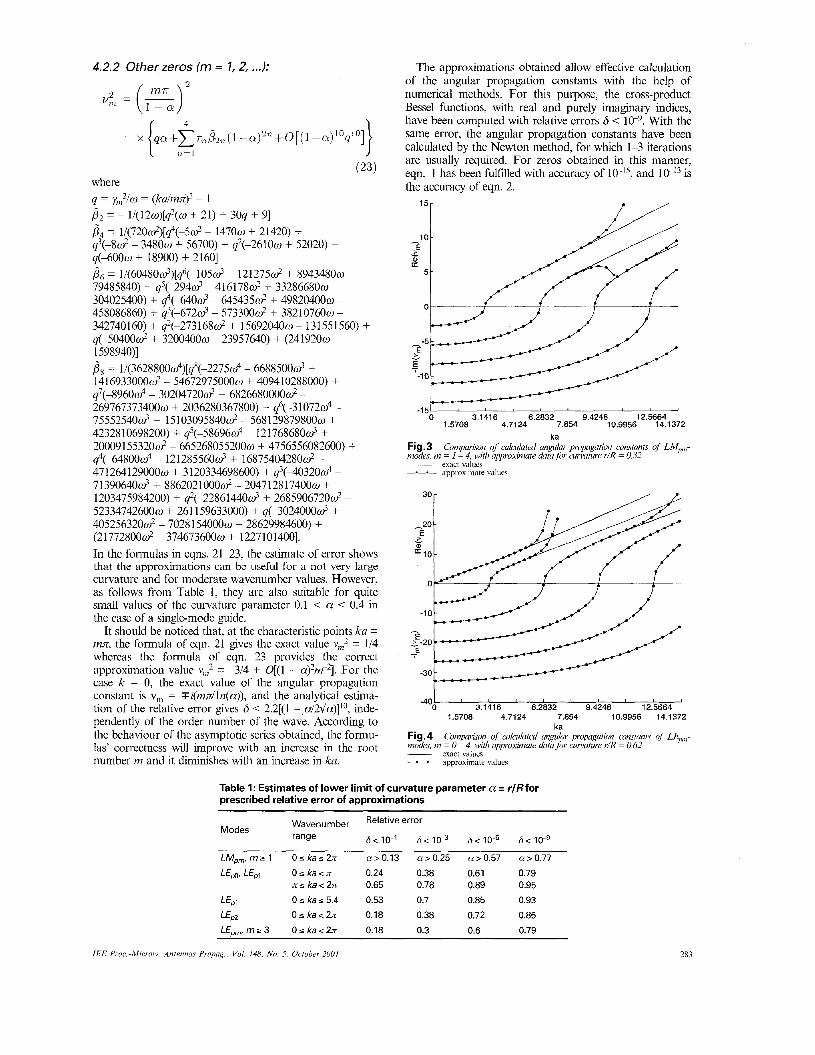
The approximations obtained allow effective calculation of the angular propagation constants with the help of numerical methods. For this purpose, the cross-product Bessel functions, with real and purely imaginary indices, have been computed with relative errors 6 < le9. With the same error, the angular propagation constants have been calculated by the Newton method, for which 1-3 iterations are usually required. For zeros obtained in this manner, eqn. 1 has been fulfdled with accuracy of and is the accuracy of eqn. 2.
-151 0 3.1416 6.2832 9.4248 12.5664
1.5708 4.7124 7.854 10.9956 14.1372 ka
Fig. 3 mo&, nz = 1 ~ 4, with upproximute datu for curvature r/R = 0.32 ~ exact values -.-.- approximate values
Cornpurism of cuIcuhted ungdur propagation conrtunts of LM,,-
- 12.5664 3.1416 6.2832 9.4248 -400
1.5708 4.7124 7.854 10.9956 14.1372 ka
Fig. 4 modes, in = 0 ~ 4, with upproxinlate datu for curvature r/R = 0.62 ~ exact values -.-.- approximate values
Coinpurhon of culmluted ungulur propugution comtunts of LE,,,-
Table I: Estimates of lower limit of curvature parameter a = r/Rfor prescribed relative error of approximations
Wavenumber Relative error Modes
range 6<10-1 6 < 1 0 - ~ 6 ~ 1 0 ~ 6 < 1 0 - ~
LMpm, m B 1 0 s ka 5 2n a > 0.13 a > 0.25 a > 0.57 a > 0.77 LEpo, LEpl 0 5 ka < n 0.24 0.38 0.61 0.79
ns k a c 2n 0.65 0.78 0.89 0.95 LEPl 0 s ka s 5.4 0.53 0.7 0.85 0.93 LEp2 O s k a c 2 n 0.18 0.38 0.72 0.85 L E p , , m ~ 3 O s k a c 2 n 0.18 0.3 0.6 0.79
IEE Proc.-Microli:. Antennas Propag.. Vol. 148, No. 5, October 2001 283
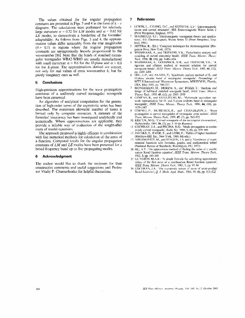
The values obtained for the angular propagation constants are presented in Figs. 3 and 4 in the form of k - Y
diagrams. The calculations were performed for relatively large curvature a = 0.32 for LM modes and a = 0.62 for LE modes, to demonstrate a borderline of the formulas’ adaptability. As follows from Figs. 3 and 4, the approxi- mation values differ noticeably from the true magnitudes (6 > 0.1) in regions where the angular propagation constants are asymptotically linearly proportional to the wavenumber {16]. Note that the bends of standard rectan- gular waveguides WR42-WR03 are usually manufactured with small curvature a > 0.6 for the H-plane and a > 0.8 for the E-plane. The approximations derived are correct, not only for real values of cross wavenumber k , but for purely imaginary ones as well.
5 Conclusions
High-precision approximations for the wave propagation constants of a uniformly curved rectangular waveguide have been presented.
An algorithm of analytical computation for the genera- tion of hgh-order terms of the asymptotic series has been described. The maximum allowable number of terms is limited only by computer resources. A measure of the formulas’ inaccuracy has been investigated analytically and numerically. Where approximations are applicable, they provide a reliable way of evaluation of the sought-after roots of modal equations.
The approach proposed is hghly efficient in combination with fast numerical methods for calculation of the zeros of a function. Computed results for the angular propagation constants of LM and LE modes have been presented for a broad frequency band up to five propagating modes.
6 Acknowledgment
The author would like to thank the reviewers for their constructive comments and useful suggestions and Profes- sor Vitaliy P. Chumachenko for helpful discussions.
7 References
1 LEWIN, L., CHANG, D.C., and KUESTER, E.F.: ‘Electromagnetic waves and curved structures’, IEE Electromagnetic Waves Series 2 (Peter Peregrinus, England, 1977)
2 MAHMOUD, S.F.: ‘Electromagnetic waveguides theory and applica- tions’, IEE Electromagnetic Waves Series 32 (Peter Peregrinus, Eng- land, 1991)
3 MITTRA, R., (Ed.): ‘Computer techniques for electromagnetics’ (Per- gamon Press, New York, 1973)
4 WEISSHAAR, A., and TRIPATHI, V.K.: ‘Perturbation analysis and modeling of curved microstrip bends’, I€EE Trms. Microw. Theory Tech., 1990, 38, (IO), pp. 149-1454
5 WEISSHAAR, A., GOODNICK, S.M., and TRIPATHI, V.K.: ‘A rigorous and efficient method of moment solution for curved waveguide bends’, IEEE Truns. Microw. Theory Tech., 1992, 40, (12), pp. 22W2206 HSU, J.-P., and ANADA, T.: ‘Systematic analysis method of E- and H-plane circular bend of rectangular waveguide’. Proceedings of MIT-S Intemational Microwave Symposium, MWSYM’95, Florida, USA, May 1995, pp. 749-752
7 MONGIARDO, M., MORINI, A., and ROZZI, T.: ‘Analysis and design of full-band matched waveguide bend‘, IEEE Trans. Microir. Theory Tech., 1995,43, (12), pp. 2965-2970 GIMENO, B., and GUGLIELMI, M.: ‘Multimode equivalent net- work representation for H- and E-plane uniform bend in rectangular waveguide’, IEEE Truns. Microw. Theory Tech., 1996, 44, (IO), pp. 1679-1687
9 CORNET, P., DUSSEAUX, R., and CHANDEZON, J.: ‘Wave propagation in curved waveguides of rectangular cross section’, IEEE Trans. Microw. Theory Tech., 1999, 41, (7), pp. 965-972
10 KISL‘UK, M.G.: ‘Curved waveguide of the rectangular cross-section’, Radiofehtziku, 1961, 16, (4), pp. 3-10 (in Russian)
11 COCHRAN, J.A., and PECINA, R.G.: ‘Mode propagation in contin- uously curved waveguide’, Radio Sci., 1966, 1, (6), pp. 679496
12 JAHNKE, E., EMDE, F., and LOSH, F.: ‘Tables of higher functions’ (McGraw-Hill, Inc., New York, 1960, 6th edn.)
13 ABRAMOWTZ, M., and STEGUN, LA. (eds.): ‘Handbook of math- ematical functions with formulas, graphs, and mathematical tables’ (National Bureau of Standards, Washington, DC, 1972)
14 HU, A.Y.: ‘An approximate method of iinding the order of a combi- nation Bessel function equation’, I€€€ Trans. Micron. Theory Tecl7..
15 GUNSTON, M.A.R.: ‘A simple formula for calculating approximate values of the first zeros of a combination Bessel function equation’, IEEE Trans. Microw. Theory Tech., 1963, 1, pp. 93-94
16 COCHRAN, J.A.: ‘The asymptotic nature of zeros of cross-product Bessel functions’, Q. J. Mech. Appl. Mufh., 1966, 19, (4), pp. 51 1-522
6
8
1962,3, pp. 145-146
284 IEE Proc.-Microw. Antennas Propog.. Vol. 148, N o . 5 , October 2003