Embed Size (px)
Citation preview
1
High-Coded Guard Lock Safety Door Switch (For Gate)
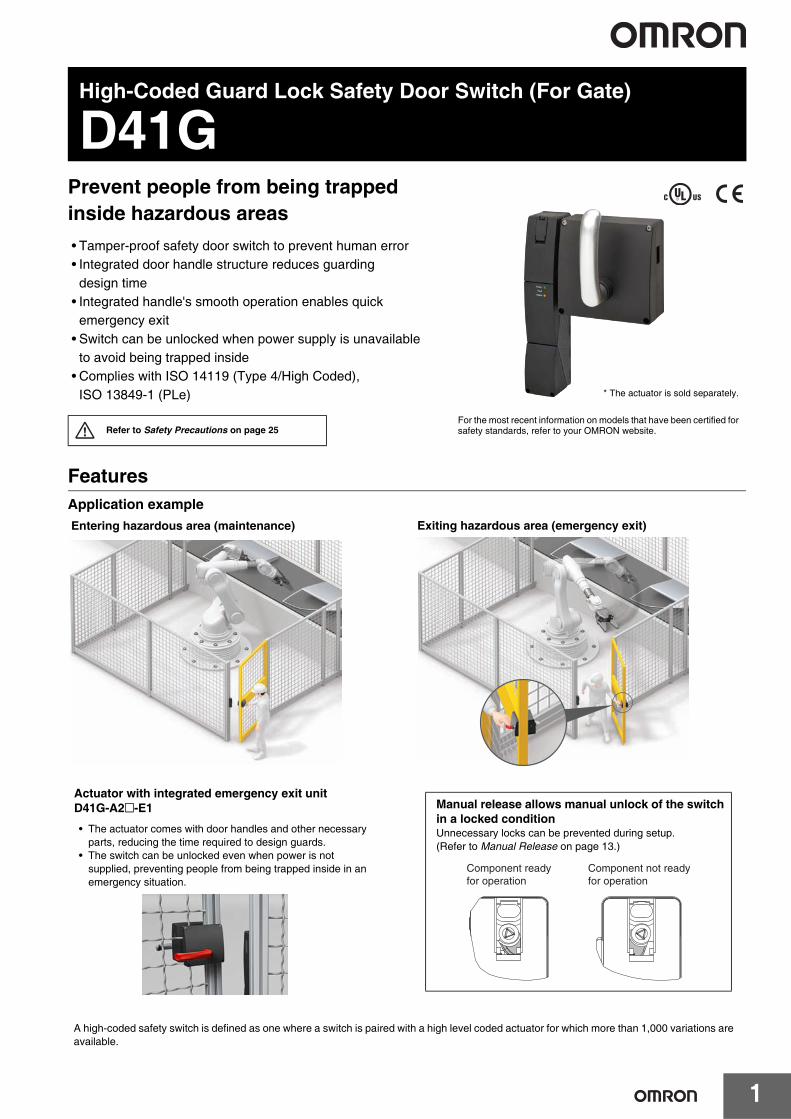
D41GPrevent people from being trapped inside hazardous areas• Tamper-proof safety door switch to prevent human error• Integrated door handle structure reduces guarding
design time• Integrated handle's smooth operation enables quick
emergency exit• Switch can be unlocked when power supply is unavailable
to avoid being trapped inside• Complies with ISO 14119 (Type 4/High Coded),
ISO 13849-1 (PLe)
FeaturesApplication example
Refer to Safety Precautions on page 25For the most recent information on models that have been certified for safety standards, refer to your OMRON website.
* The actuator is sold separately.
Entering hazardous area (maintenance) Exiting hazardous area (emergency exit)
Actuator with integrated emergency exit unitD41G-A2@-E1
• The actuator comes with door handles and other necessary parts, reducing the time required to design guards.
• The switch can be unlocked even when power is not supplied, preventing people from being trapped inside in an emergency situation.
Manual release allows manual unlock of the switch in a locked conditionUnnecessary locks can be prevented during setup.(Refer to Manual Release on page 13.)
Component readyfor operation
Component not readyfor operation
A high-coded safety switch is defined as one where a switch is paired with a high level coded actuator for which more than 1,000 variations are available.
D41G
2
Model Number StructureModel Number LegendSafety Door SwitchSwitch
Actuator
D41G - @ @ D @ - @ (2) (3)(1) (4) (5) (6)
(1) ModelG: Guard Lock (For Gate)
(2) Coding level / Teaching limitation1: High (Individual coding) / Teaching is not-repeatable2: High (Individual coding) / Teaching is repeatable
(3) OSSD configurationY: Guard monitoring AND lock monitoringZ: Only guard monitoring
(4) Diagnosis outputD: With diagnosis output
(5) Lock and releaseA: Power to unlock (Mechanical lock / Solenoid release)G: Power to lock (Solenoid lock/ Mechanical release)
(6) Connection methodN2: M12 ConnectorT1: Screw terminal (Conduit outlet M20)
D41G - A @ @ - @ @(2)(1)
(1) ModelG: Guard Lock (For Gate)
(2) Actuator typeA1: None door-handle (for sliding safety guards)A2: With door-handle (for hinged or sliding safety guards)
(3) Handle positionL: Left (Actuator is installed on left of switch)R: Right (Actuator is installed on right of switch)
(4) Emergency functionBlank: None functionE0: With emergency release tab (D41G-A1 only)E1: With emergency exit unit (D41G-A2 only)
(5) Lock-out option (D41G-A2 only)Blank: None optionT: With Lock-out tag
(3) (5)(4)
D41G
3
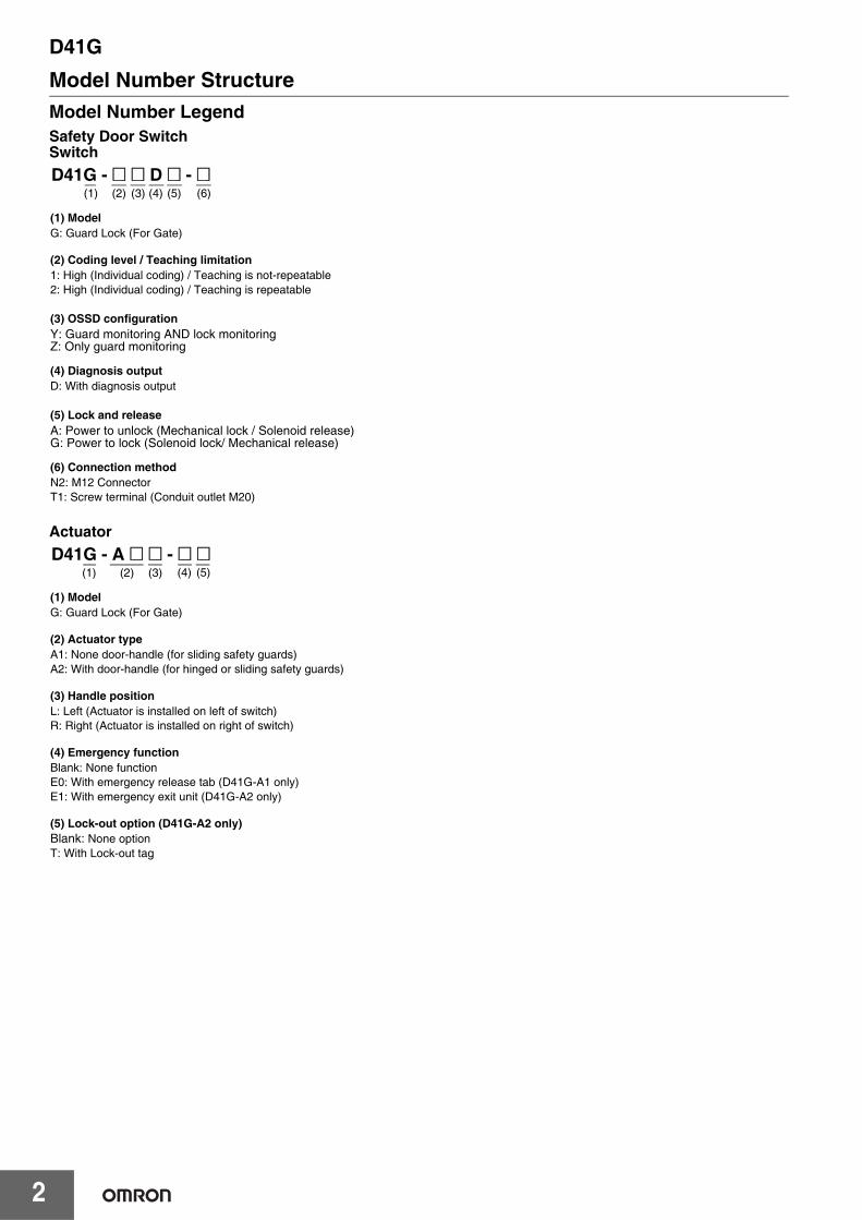
Ordering InformationList of ModelsSwitches
Actuators (Sold separately)
Accessory (Sold separately)Connecting cables
Classification (Lock and Release) Appearance Coding level /
Teaching limitation OSSD configuration Connection method Model
Power to unlock (Mechanical lock/ Solenoid release)
High / Teaching is not-repeatable
Guard monitoring AND lock monitoring
Screw terminal D41G-1YDA-T1M12 Connector D41G-1YDA-N2
High / Teaching is repeatable
Only guard monitoring Screw terminal D41G-2ZDA-T1
Guard monitoring AND lock monitoring
Screw terminal D41G-2YDA-T1M12 Connector D41G-2YDA-N2
Power to lock (Solenoid lock/
Mechanical release)
High / Teaching is repeatable
Only guard monitoringScrew terminal D41G-2ZDG-T1M12 Connector D41G-2ZDG-N2
Guard monitoring AND lock monitoring
Screw terminal D41G-2YDG-T1M12 Connector D41G-2YDG-N2
Actuator type Appearance Handle position Emergency function Lock-out option Model
With door-handle
Left
--- --- D41G-A2L
With emergency exit unit --- D41G-A2L-E1
With emergency exit unit With Lock-out tag D41G-A2L-E1T
Right
--- --- D41G-A2R
With emergency exit unit --- D41G-A2R-E1
With emergency exit unit With Lock-out tag D41G-A2R-E1T
None door-handle
Left
--- --- D41G-A1L
With emergency release tab --- D41G-A1L-E0
Right
--- --- D41G-A1R
With emergency release tab --- D41G-A1R-E0
Appearance Name Features Cable length Model
Connecting cables with Connector M12
Connecting cablewith connector (M12) (female),8-pole – 8 x 0.25 mm2, straight,IP69
5 m D41L-8P5-CFM12-905M
10 m D41L-8P5-CFM12-910M
D41G
4
Standards CertificationDirectives• Machinery Directive• RE Directive• RoHS Directive• WEEE Directive
Dispose in accordance with applicable regulations.
Standards• EN ISO 13849-1: PL e Category 4• EN 60947-5-3• EN 300 330• IEC 61508• EN 62061• EN ISO 14119
UL Certification• UL508• CAN/CSA C22.2 No.14
Regions where D41G can be usedThe product can be used in Japan, the United States, Canada, EU member states, the United Kingdom, China, Australia, and New Zealand.The use in other countries may conflict with radio laws of the countries.
D41G
5
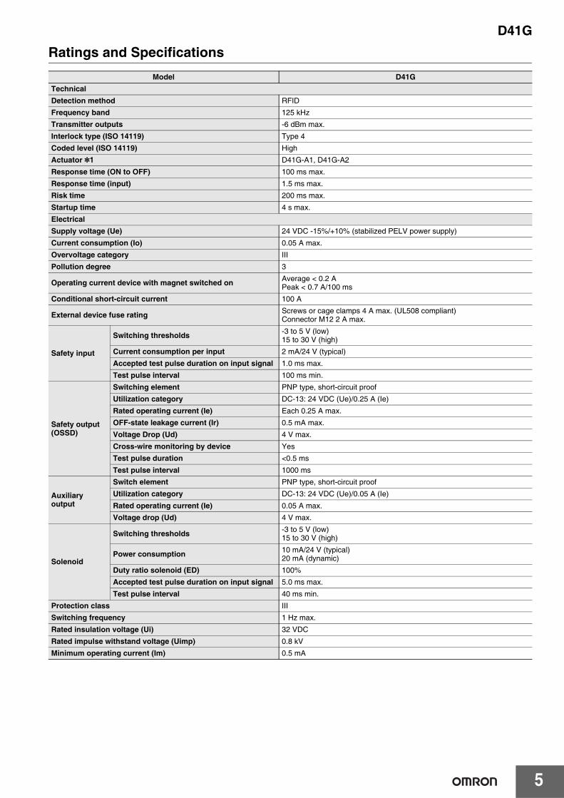
Ratings and SpecificationsModel D41G
TechnicalDetection method RFID
Frequency band 125 kHz
Transmitter outputs -6 dBm max.
Interlock type (ISO 14119) Type 4
Coded level (ISO 14119) High
Actuator *1 D41G-A1, D41G-A2
Response time (ON to OFF) 100 ms max.
Response time (input) 1.5 ms max.
Risk time 200 ms max.
Startup time 4 s max.
ElectricalSupply voltage (Ue) 24 VDC -15%/+10% (stabilized PELV power supply)
Current consumption (Io) 0.05 A max.
Overvoltage category III
Pollution degree 3
Operating current device with magnet switched on Average < 0.2 A Peak < 0.7 A/100 ms
Conditional short-circuit current 100 A
External device fuse rating Screws or cage clamps 4 A max. (UL508 compliant) Connector M12 2 A max.
Safety input
Switching thresholds -3 to 5 V (low) 15 to 30 V (high)
Current consumption per input 2 mA/24 V (typical)
Accepted test pulse duration on input signal 1.0 ms max.
Test pulse interval 100 ms min.
Safety output (OSSD)
Switching element PNP type, short-circuit proof
Utilization category DC-13: 24 VDC (Ue)/0.25 A (Ie)
Rated operating current (Ie) Each 0.25 A max.
OFF-state leakage current (Ir) 0.5 mA max.
Voltage Drop (Ud) 4 V max.
Cross-wire monitoring by device Yes
Test pulse duration <0.5 ms
Test pulse interval 1000 ms
Auxiliary output
Switch element PNP type, short-circuit proof
Utilization category DC-13: 24 VDC (Ue)/0.05 A (Ie)
Rated operating current (Ie) 0.05 A max.
Voltage drop (Ud) 4 V max.
Solenoid
Switching thresholds -3 to 5 V (low) 15 to 30 V (high)
Power consumption 10 mA/24 V (typical) 20 mA (dynamic)
Duty ratio solenoid (ED) 100%
Accepted test pulse duration on input signal 5.0 ms max.
Test pulse interval 40 ms min.
Protection class III
Switching frequency 1 Hz max.
Rated insulation voltage (Ui) 32 VDC
Rated impulse withstand voltage (Uimp) 0.8 kV
Minimum operating current (Im) 0.5 mA
D41G
6
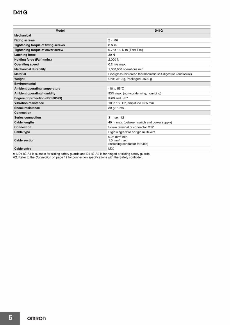
*1. D41G-A1 is suitable for sliding safety guards and D41G-A2 is for hinged or sliding safety guards.*2. Refer to the Connection on page 12 for connection specifications with the Safety controller.
MechanicalFixing screws 2 × M6
Tightening torque of fixing screws 8 N·m
Tightening torque of cover screw 0.7 to 1.0 N·m (Torx T10)
Latching force 30 N
Holding force (Fzh) (min.) 2,000 N
Operating speed 0.2 m/s max.
Mechanical durability 1,000,000 operations min.
Material Fiberglass reinforced thermoplastic self-digestion (enclosure)
Weight Unit: <510 g, Packaged: <600 g
EnvironmentalAmbient operating temperature -10 to 55°C
Ambient operating humidity 93% max. (non-condensing, non-icing)
Degree of protection (IEC 60529) IP66 and IP67
Vibration resistance 10 to 150 Hz, amplitude 0.35 mm
Shock resistance 30 g/11 ms
ConnectionSeries connection 31 max. *2
Cable lengths 40 m max. (between switch and power supply)
Connection Screw terminal or connector M12
Cable type Rigid single-wire or rigid multi-wire
Cable section0.25 mm2 min.1.5 mm2 max.(including conductor ferrules)
Cable entry M20
Model D41G
D41G
7
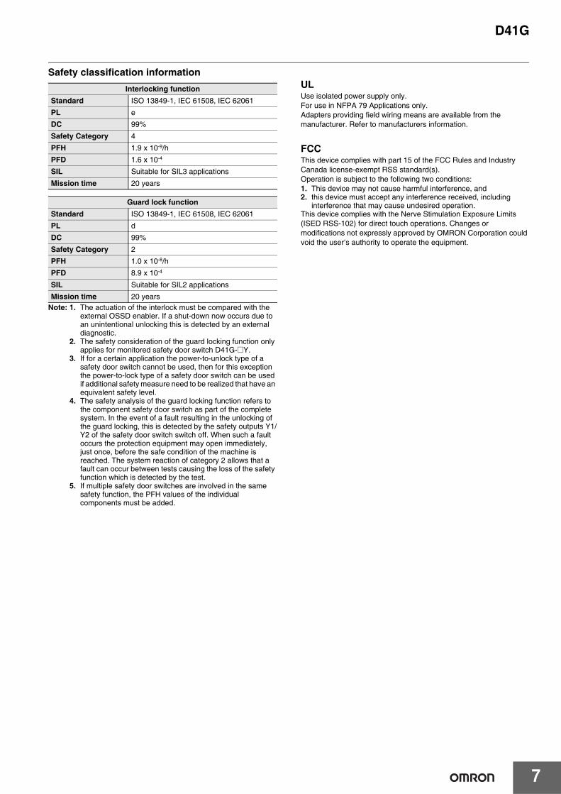
Safety classification information
Note: 1. The actuation of the interlock must be compared with the external OSSD enabler. If a shut-down now occurs due to an unintentional unlocking this is detected by an external diagnostic.
2. The safety consideration of the guard locking function only applies for monitored safety door switch D41G-@Y.
3. If for a certain application the power-to-unlock type of a safety door switch cannot be used, then for this exception the power-to-lock type of a safety door switch can be used if additional safety measure need to be realized that have an equivalent safety level.
4. The safety analysis of the guard locking function refers to the component safety door switch as part of the complete system. In the event of a fault resulting in the unlocking of the guard locking, this is detected by the safety outputs Y1/Y2 of the safety door switch switch off. When such a fault occurs the protection equipment may open immediately, just once, before the safe condition of the machine is reached. The system reaction of category 2 allows that a fault can occur between tests causing the loss of the safety function which is detected by the test.
5. If multiple safety door switches are involved in the same safety function, the PFH values of the individual components must be added.
ULUse isolated power supply only. For use in NFPA 79 Applications only.Adapters providing field wiring means are available from the manufacturer. Refer to manufacturers information.
FCCThis device complies with part 15 of the FCC Rules and Industry Canada license-exempt RSS standard(s).Operation is subject to the following two conditions:1. This device may not cause harmful interference, and2. this device must accept any interference received, including
interference that may cause undesired operation.This device complies with the Nerve Stimulation Exposure Limits (ISED RSS-102) for direct touch operations. Changes or modifications not expressly approved by OMRON Corporation could void the user‘s authority to operate the equipment.
Interlocking functionStandard ISO 13849-1, IEC 61508, IEC 62061
PL e
DC 99%
Safety Category 4
PFH 1.9 x 10⁻⁹/h
PFD 1.6 x 10⁻⁴
SIL Suitable for SIL3 applications
Mission time 20 years
Guard lock functionStandard ISO 13849-1, IEC 61508, IEC 62061
PL d
DC 99%
Safety Category 2
PFH 1.0 x 10⁻⁸/h
PFD 8.9 x 10⁻⁴
SIL Suitable for SIL2 applications
Mission time 20 years
D41G
8
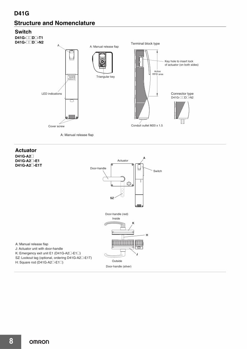
Structure and Nomenclature
PowerFault
Status
Key hole to insert lock of actuator (on both sides)
Active RFID area
Connector typeD41G-@@D@-N2
Conduit outlet M20 x 1.5
Triangular key
A: Manual release flap
Cover screw
ATerminal block type
A: Manual release flap
LED indications
SwitchD41G-@@D@-T1D41G-@@D@-N2
J
Door-handle (red)
Actuator
Inside
Outside
Door-handle (silver)
SwitchDoor-handle
K
H
A
SZ
A: Manual release flapJ: Actuator unit with door-handleK: Emergency exit unit E1 (D41G-A2@-E1@)SZ: Lockout tag (optional, ordering D41G-A2@-E1T)H: Square rod (D41G-A2@-E1@)
ActuatorD41G-A2@D41G-A2@-E1D41G-A2@-E1T
D41G
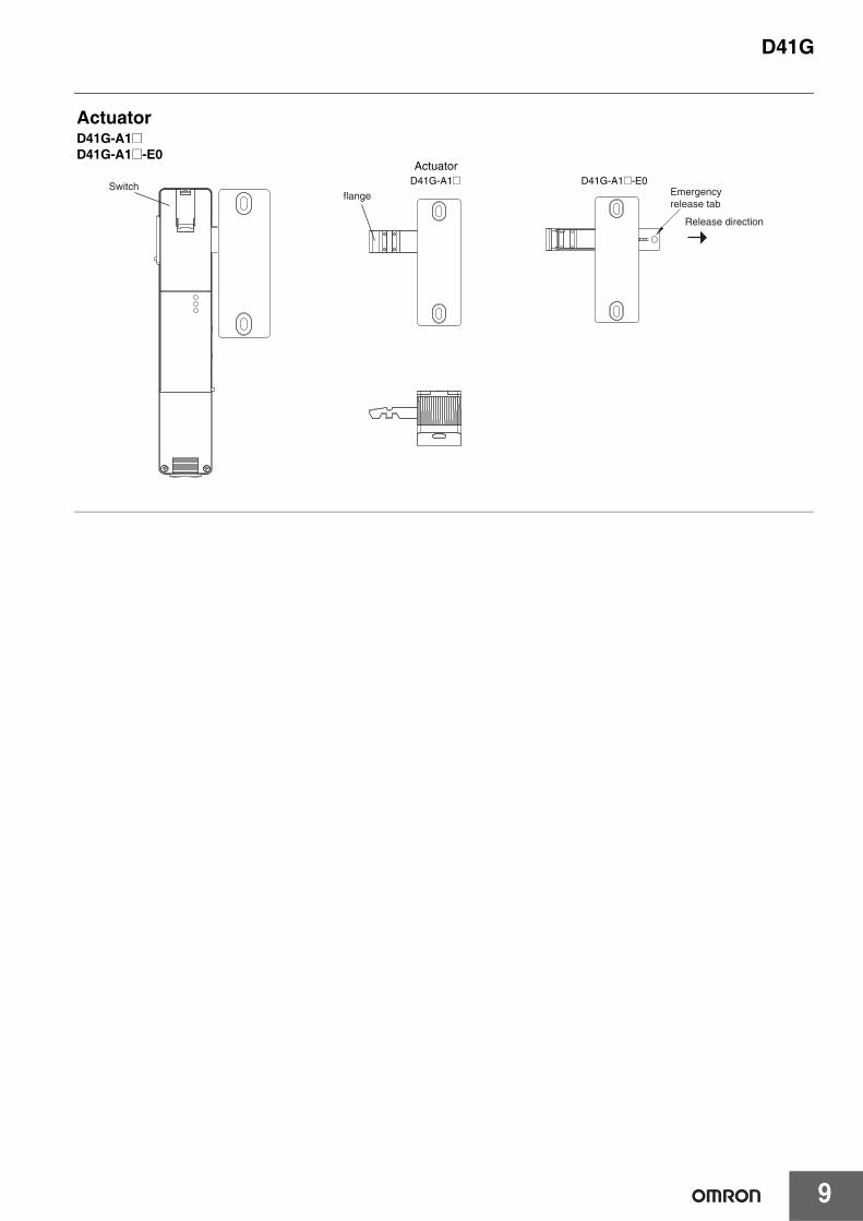
9
Emergencyrelease tab
Switchflange
D41G-A1@Actuator
D41G-A1@-E0
Release direction
ActuatorD41G-A1@D41G-A1@-E0
D41G
10
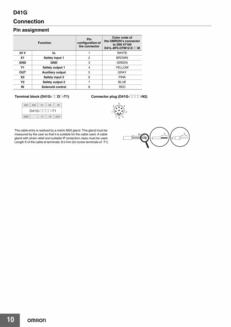
ConnectionPin assignment
FunctionPin
configuration of the connector
Color code ofthe OMRON’s connector
to DIN 47100D41L-8P5-CFM12-9@@M
24 V Ue 1 WHITE
X1 Safety input 1 2 BROWN
GND GND 3 GREEN
Y1 Safety output 1 4 YELLOW
OUT Auxiliary output 5 GRAY
X2 Safety input 2 6 PINK
Y2 Safety output 2 7 BLUE
IN Solenoid control 8 RED
X X40The cable entry is realized by a metric M20 gland. This gland must be measured by the user so that it is suitable for the cable used. A cable gland with strain relief and suitable IP protection class must be used.Length X of the cable at terminals: 8.0 mm (for screw terminals of -T1)
Terminal block (D41G-@@D@-T1)
Y1 Y2 OUTGND
24V 24V X1 X2 IN
D41G-@@@@-T1
Connector plug (D41G-@@@@-N2)
5
8
4
3
21
7
6
D41G
11
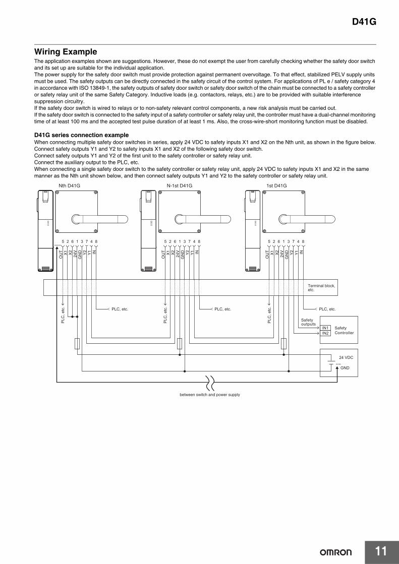
Wiring ExampleThe application examples shown are suggestions. However, these do not exempt the user from carefully checking whether the safety door switch and its set up are suitable for the individual application.The power supply for the safety door switch must provide protection against permanent overvoltage. To that effect, stabilized PELV supply units must be used. The safety outputs can be directly connected in the safety circuit of the control system. For applications of PL e / safety category 4 in accordance with ISO 13849-1, the safety outputs of safety door switch or safety door switch of the chain must be connected to a safety controller or safety relay unit of the same Safety Category. Inductive loads (e.g. contactors, relays, etc.) are to be provided with suitable interference suppression circuitry.If the safety door switch is wired to relays or to non-safety relevant control components, a new risk analysis must be carried out.If the safety door switch is connected to the safety input of a safety controller or safety relay unit, the controller must have a dual-channel monitoring time of at least 100 ms and the accepted test pulse duration of at least 1 ms. Also, the cross-wire-short monitoring function must be disabled.
D41G series connection exampleWhen connecting multiple safety door switches in series, apply 24 VDC to safety inputs X1 and X2 on the Nth unit, as shown in the figure below.Connect safety outputs Y1 and Y2 to safety inputs X1 and X2 of the following safety door switch.Connect safety outputs Y1 and Y2 of the first unit to the safety controller or safety relay unit.Connect the auxiliary output to the PLC, etc.When connecting a single safety door switch to the safety controller or safety relay unit, apply 24 VDC to safety inputs X1 and X2 in the same manner as the Nth unit shown below, and then connect safety outputs Y1 and Y2 to the safety controller or safety relay unit.
1 325 6 8
X1
4
Y1 INX2
7
Y2
OU
T
24V
GN
D X1
Y1 INX2
Y2
OU
T
24V
GN
D X1
Y1 INX2
Y2
OU
T
24V
GN
D
1 325 6 847 1 325 6 847
Nth D41G N-1st D41G 1st D41G
Terminal block, etc.
Safetyoutputs
between switch and power supply
PLC
, etc
.
PLC
, etc
.
PLC
, etc
.
IN1IN2
24 VDC
GND
SafetyController
PLC, etc. PLC, etc.PLC, etc.
D41G
12
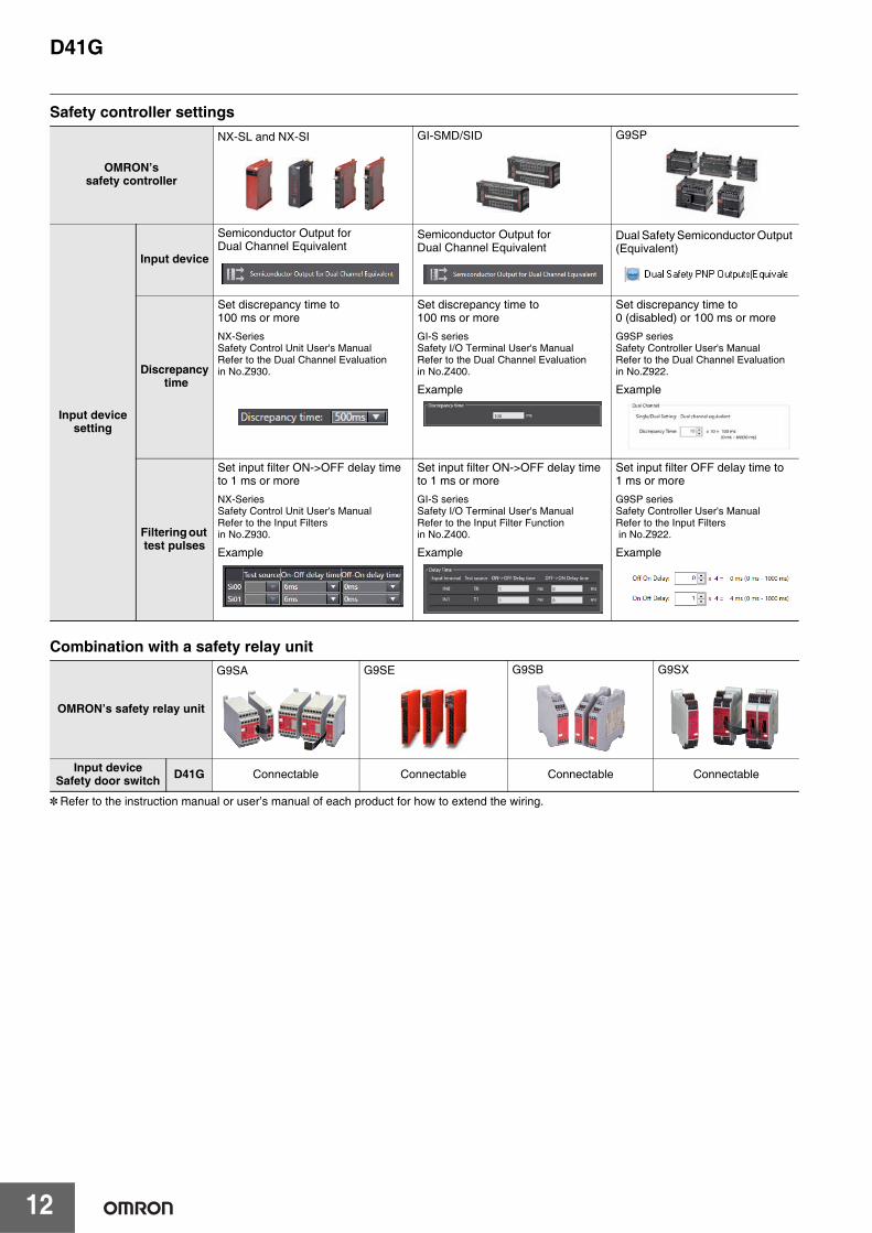
Safety controller settings
Combination with a safety relay unit
* Refer to the instruction manual or user’s manual of each product for how to extend the wiring.
OMRON’s safety controller
NX-SL and NX-SI GI-SMD/SID G9SP
Input device setting
Input device
Semiconductor Output for Dual Channel Equivalent
Semiconductor Output for Dual Channel Equivalent
Dual Safety Semiconductor Output (Equivalent)
Discrepancy time
Set discrepancy time to 100 ms or more
NX-SeriesSafety Control Unit User's ManualRefer to the Dual Channel Evaluation in No.Z930.
Set discrepancy time to 100 ms or more
GI-S seriesSafety I/O Terminal User's ManualRefer to the Dual Channel Evaluation in No.Z400.
Example
Set discrepancy time to 0 (disabled) or 100 ms or more
G9SP seriesSafety Controller User's ManualRefer to the Dual Channel Evaluation in No.Z922.
Example
Filtering out test pulses
Set input filter ON->OFF delay time to 1 ms or more
NX-SeriesSafety Control Unit User's ManualRefer to the Input Filters in No.Z930.
Example
Set input filter ON->OFF delay time to 1 ms or more
GI-S seriesSafety I/O Terminal User's ManualRefer to the Input Filter Function in No.Z400.
Example
Set input filter OFF delay time to 1 ms or more
G9SP seriesSafety Controller User's ManualRefer to the Input Filters in No.Z922.
Example
OMRON’s safety relay unit
G9SA G9SE G9SB G9SX
Input deviceSafety door switch D41G Connectable Connectable Connectable Connectable
D41G
13
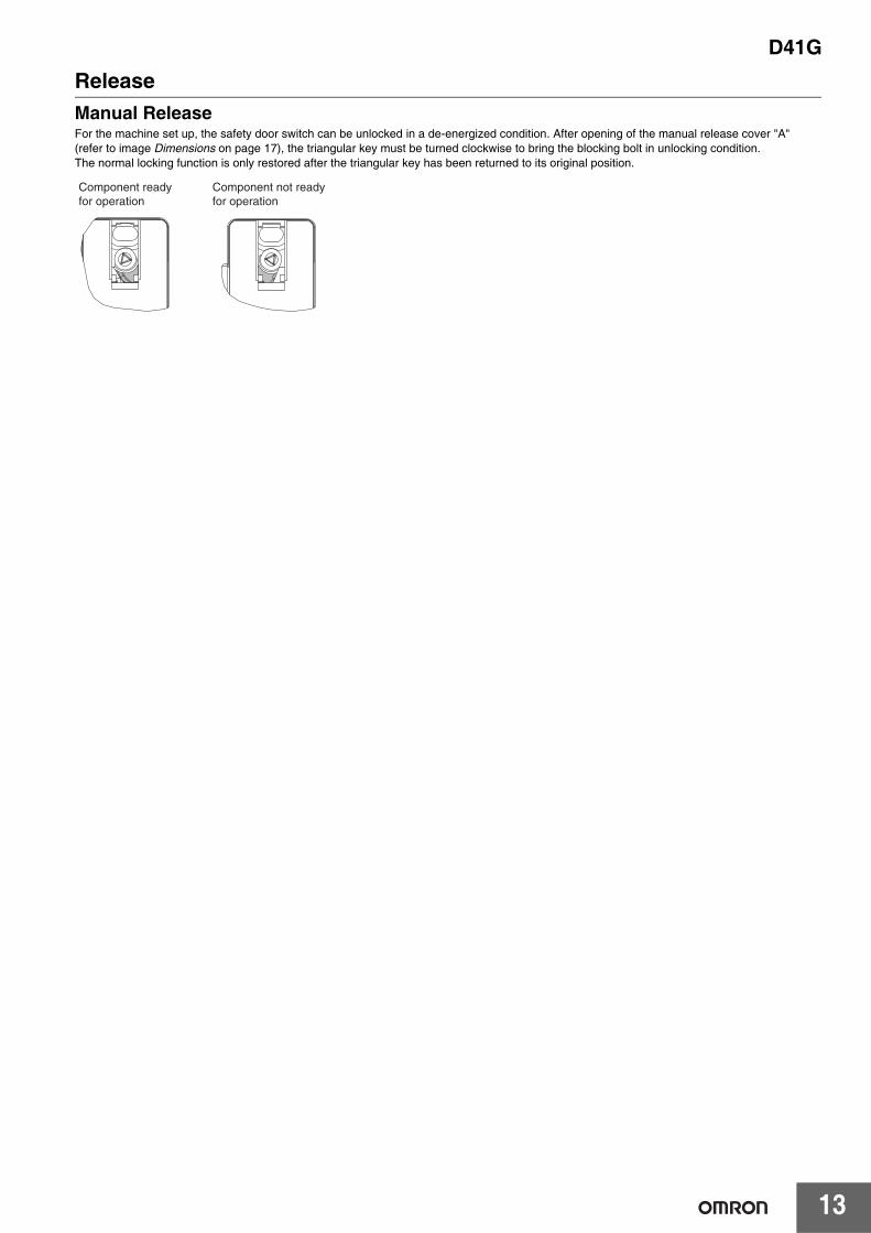
ReleaseManual ReleaseFor the machine set up, the safety door switch can be unlocked in a de-energized condition. After opening of the manual release cover "A" (refer to image Dimensions on page 17), the triangular key must be turned clockwise to bring the blocking bolt in unlocking condition.The normal locking function is only restored after the triangular key has been returned to its original position.
Component readyfor operation
Component not readyfor operation
D41G
14
TeachingIndividually coded safety door switch and actuators will require the following teach-in procedure:
1. Keep the actuator away from the detection range and switch the safety door switch's voltage supply off and back on.2. Introduce the actuator in the detection range. The teach-in procedure is signaled at the safety door switch, green LED off, red LED on, yellow
LED flashes (1 Hz).3. After 10 seconds, the yellow LED gives brief cyclic flashes (3 Hz). Switch off the supply voltage of the safety door switch. (If the voltage is not
switched off within 5 minutes, the safety door switch cancels the teach-in procedure and signals a false actuator by 5 red flashes).4. Switch the supply voltage back on. The actuator must be detected once more in order to activate the taught actuator code. In this way, the
activated code is definitively saved.
For ordering suffix D41G-1, the executed allocation of safety interlock and actuator is irreversible.When the above procedure is attempted with a D41G-1 which already completed teaching, the teaching procedure will not start.
For ordering suffix D41G-2, the teach-in procedure for a new actuator can be repeated an unlimited number of times. When a new actuator is taught, the code, which was applicable until that moment, becomes invalid. Subsequent to that, the safety outputs will be disabled for ten minutes, thus providing for an increased protection against intentional tampering. The green LED will flash until the expiration of the time (10 minutes) of the enabling inhibit and the detection of the new actuator. In case of power failure during the lapse of time, the 10-minutes tampering protection time will restart.When the above procedure is attempted with a combination of D41G-2 and actuator which already completed teaching, the teaching procedure will not start.
D41G
15
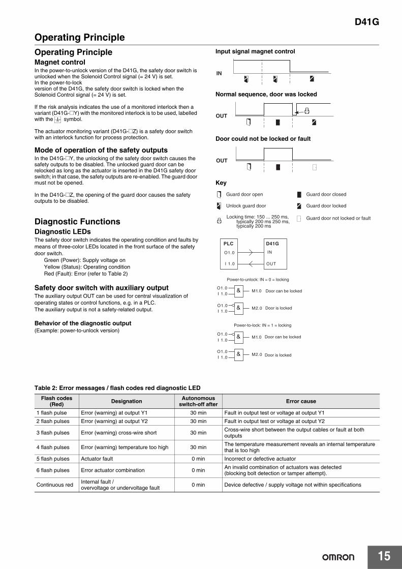
Operating PrincipleOperating PrincipleMagnet controlIn the power-to-unlock version of the D41G, the safety door switch is unlocked when the Solenoid Control signal (= 24 V) is set.In the power-to-lockversion of the D41G, the safety door switch is locked when the Solenoid Control signal (= 24 V) is set.
If the risk analysis indicates the use of a monitored interlock then a variant (D41G-@Y) with the monitored interlock is to be used, labelled with the symbol.
The actuator monitoring variant (D41G-@Z) is a safety door switch with an interlock function for process protection.
Mode of operation of the safety outputsIn the D41G-@Y, the unlocking of the safety door switch causes the safety outputs to be disabled. The unlocked guard door can be relocked as long as the actuator is inserted in the D41G safety door switch; in that case, the safety outputs are re-enabled. The guard door must not be opened.
In the D41G-@Z, the opening of the guard door causes the safety outputs to be disabled.
Diagnostic FunctionsDiagnostic LEDsThe safety door switch indicates the operating condition and faults bymeans of three-color LEDs located in the front surface of the safety door switch.
Green (Power): Supply voltage onYellow (Status): Operating conditionRed (Fault): Error (refer to Table 2)
Safety door switch with auxiliary outputThe auxiliary output OUT can be used for central visualization of operating states or control functions, e.g. in a PLC.The auxiliary output is not a safety-related output.
Behavior of the diagnostic output(Example: power-to-unlock version)
Input signal magnet control
Normal sequence, door was locked
Door could not be locked or fault
Key
Table 2: Error messages / flash codes red diagnostic LED
IN
OUT
OUT
Guard door open Guard door closed
Unlock guard door
Locking time: 150 ... 250 ms,
Guard door locked
typically 200 ms 250 ms, typically 200 ms
Guard door not locked or fault
AZM200
IN
OUTI 1.0
O1.0
O1.0I 1.0
O1.0I 1.0
M1.0
M1.0
M2.0
M2.0
&
&
O1.0I 1.0
&
O1.0I 1.0
&
Door can be locked
Door can be locked
Power-to-unlock: IN = 0 = locking
Door is locked
Door is locked
Power-to-lock: IN = 1 = locking
D41GPLC
Flash codes(Red) Designation Autonomous
switch-off after Error cause
1 flash pulse Error (warning) at output Y1 30 min Fault in output test or voltage at output Y1
2 flash pulses Error (warning) at output Y2 30 min Fault in output test or voltage at output Y2
3 flash pulses Error (warning) cross-wire short 30 min Cross-wire short between the output cables or fault at both outputs
4 flash pulses Error (warning) temperature too high 30 min The temperature measurement reveals an internal temperature that is too high
5 flash pulses Actuator fault 0 min Incorrect or defective actuator
6 flash pulses Error actuator combination 0 min An invalid combination of actuators was detected (blocking bolt detection or tamper attempt).
Continuous red Internal fault / overvoltage or undervoltage fault 0 min Device defective / supply voltage not within specifications
D41G
16
ActuatorIntroductionD41G-AMounting of the safety door switch and the actuator Refer to the D41G actuator's Quick Installation Manual for the corresponding actuator.The actuator must be permanently fitted to the guard doors and protected against displacement by suitable measures (tamper-proof screws, gluing, drilling of the screw heads).
Destination and UseD41G-A2In conjunction with the safety door switch D41G the actuator is suitable for hinged and sliding guard doors. The guard door can be opened and closed from outside by turning the door-handle.
The actuator is pulled into the actuator unit by a spring. The actuator unit with emergency exit is used to open the guard door inside the hazardous area. By actuating the emergency exit, the guard door can be opened from within the hazardous area without the need for unlocking the safety door switch D41G. The guard door cannot be locked from inside. On accessible protective equipment, the lockout tag prevents persons from being inadvertently being trapped. When entering the hazardous area, each member of the operating or service team fixes a lock to the lockout tag to prevent the locking of the guard door and therefore any inadvertent machine start.
Holding force Fzh- mounting outside 2,000 N
D41G-A1Actuators D41G-A1 is the preferred choice for use on sliding guard doors. Actuator D41G-A1-E0 only suitable for the safety door switch D41G with concealed installation.
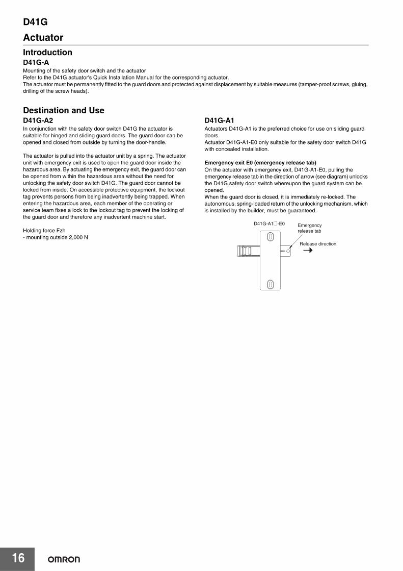
Emergency exit E0 (emergency release tab)On the actuator with emergency exit, D41G-A1-E0, pulling the emergency release tab in the direction of arrow (see diagram) unlocks the D41G safety door switch whereupon the guard system can be opened.When the guard door is closed, it is immediately re-locked. The autonomous, spring-loaded return of the unlocking mechanism, which is installed by the builder, must be guaranteed.
Emergencyrelease tab
D41G-A1@-E0
Release direction
D41G
17
Dimensions (Unit: mm)
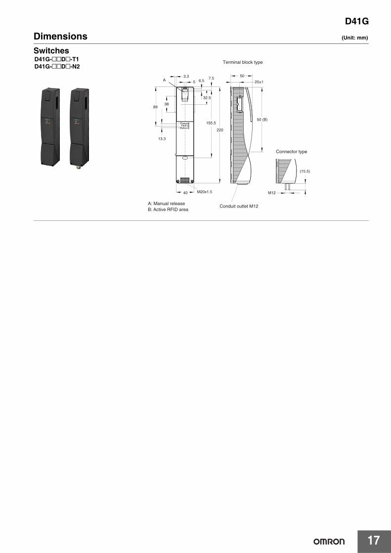
Switches
PowerFault
Status
A
38
13.3
89
5 6.5
32.5
3.3
220
155.5
7.5
40 M20x1.5
A: Manual releaseB: Active RFID area
20±1
50
50 (B)
Terminal block type
Conduit outlet M12
M12
(15.5)
Connector type
D41G-@@D@-T1D41G-@@D@-N2
D41G
18
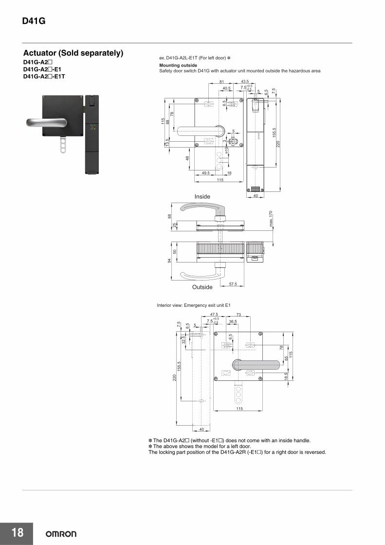
Actuator (Sold separately)D41G-A2@D41G-A2@-E1D41G-A2@-E1T
* The D41G-A2@ (without -E1@) does not come with an inside handle. * The above shows the model for a left door.The locking part position of the D41G-A2R (-E1@) for a right door is reversed.
Mounting outsideSafety door switch D41G with actuator unit mounted outside the hazardous area
Interior view: Emergency exit unit E1
Outside
Inside
ex. D41G-A2L-E1T (For left door) *
115
115
8813
.578
220
6.5
155.
5
43.58140.5
5 6.5 7.5
40
5
3
1649.5
¤10
48
7.5+0.5-2.5
115
115
6518
.578
220
6.5
155.
5
7347.5
36.556.
532
.57.
5
40
7.5+0.5-2.5
9468
5025
57.5
max
.170
D41G
19
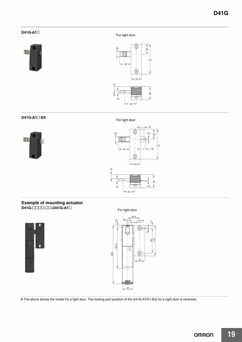
* The above shows the model for a light door. The locking part position of the D41G-A1R (-E0) for a right door is reversed.
20
15
10
115
50
39
45
44
40
D41G-A1@For light door
20
115
39
44
40
5.5
19
14
10
45
1.5
15
50
D41G-A1@-E0For light door
40
11
5
115
93
40
7.5
155.
5
220
55 1.5±
46.5
Example of mounting actuatorD41G-@@@@-@@+D41G-A1@ For light door
D41G
20
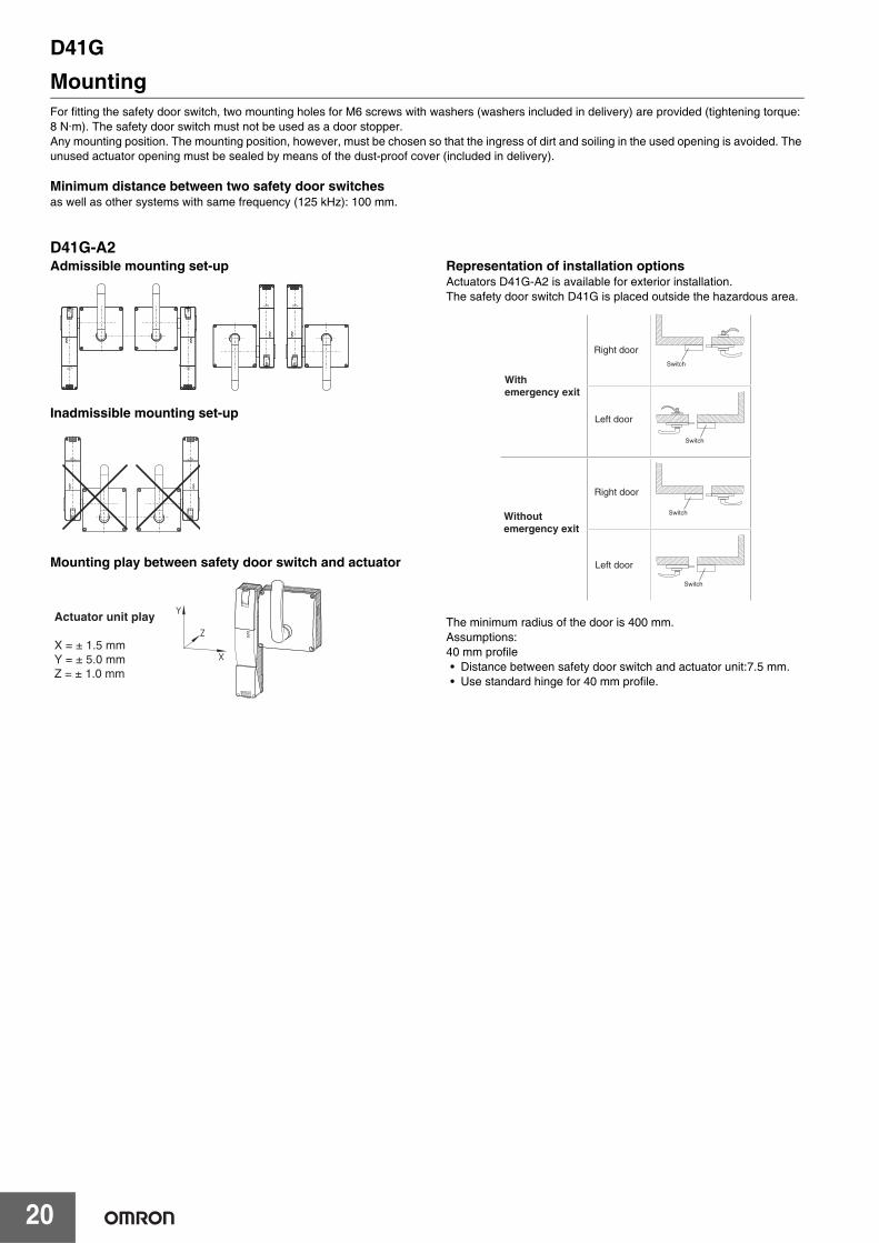
MountingFor fitting the safety door switch, two mounting holes for M6 screws with washers (washers included in delivery) are provided (tightening torque: 8 N·m). The safety door switch must not be used as a door stopper.Any mounting position. The mounting position, however, must be chosen so that the ingress of dirt and soiling in the used opening is avoided. The unused actuator opening must be sealed by means of the dust-proof cover (included in delivery).
Minimum distance between two safety door switches as well as other systems with same frequency (125 kHz): 100 mm.
D41G-A2Admissible mounting set-up
Inadmissible mounting set-up
Mounting play between safety door switch and actuator
Representation of installation optionsActuators D41G-A2 is available for exterior installation. The safety door switch D41G is placed outside the hazardous area.
The minimum radius of the door is 400 mm.Assumptions:40 mm profile• Distance between safety door switch and actuator unit:7.5 mm.• Use standard hinge for 40 mm profile.
Actuator unit play
X = ± 1.5 mmY = ± 5.0 mmZ = ± 1.0 mm
With emergency exit
Switch
Without emergency exit
Switch
Switch
Switch
Right door
Left door
Right door
Left door
D41G
21
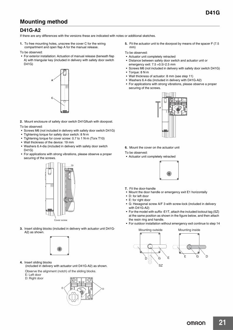
Mounting methodD41G-A2If there are any differences with the versions these are indicated with notes or additional sketches.
1. To free mounting holes, unscrew the cover C for the wiring compartment and open flap A for the manual release.
To be observed:• For exterior installation: Actuation of manual release (beneath flap
A) with triangular key (included in delivery with safety door switch D41G)
2. Mount enclosure of safety door switch D41Gflush with doorpost.
To be observed:• Screws M6 (not included in delivery with safety door switch D41G)• Tightening torque for safety door switch: 8 N·m• Tightening torque for cover screw: 0.7 to 1 N·m (Torx T10)• Wall thickness of the device: 19 mm• Washers 6.4-dia (included in delivery with safety door switch
D41G)• For applications with strong vibrations, please observe a proper
securing of the screws.
3. Insert sliding blocks (included in delivery with actuator unit D41G-A2) as shown.
4. Insert sliding blocks (included in delivery with actuator unit D41G-A2) as shown.
5. Fit the actuator unit to the doorpost by means of the spacer F (7.5 mm)
To be observed:• Actuator unit completely retracted• Distance between safety door switch and actuator unit or
emergency exit: 7.5 +0.5/-2.5 mm• Screws M6 (not included in delivery with safety door switch D41G)• Torque: 8 N·m• Wall thickness of actuator: 8 mm (see step 11)• Washers 6.4-dia (included in delivery with D41G-A2)• For applications with strong vibrations, please observe a proper
securing of the screws.
6. Mount the cover on the actuator unit
To be observed:• Actuator unit completely retracted
7. Fit the door-handle• Mount the door handle or emergency exit E1 horizontally• D: for left door• E: for right door• G: Hexagonal screw A/F 3 with screw-lock (included in delivery
with D41G-A2)• For the model with suffix -E1T, attach the included lockout tag (SZ)
at the same position as shown in the figure below, and then attach the resin ring and handle.
• For outdoor installation without emergency exit continue to step 14
A
C
GNRDYE
•
•
•
19
GNRDYE
Cover screw
Observe the alignment (notch) of the sliding blocks. E: Left door D: Right door
E D
F
EG
SZ
DDE G
Mounting outside Mounting inside
D41G
22
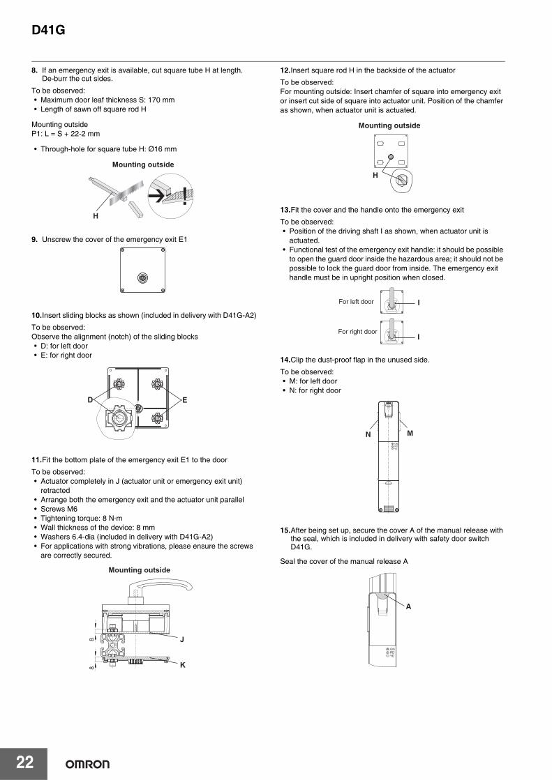
8. If an emergency exit is available, cut square tube H at length. De-burr the cut sides.
To be observed:• Maximum door leaf thickness S: 170 mm• Length of sawn off square rod H
Mounting outsideP1: L = S + 22-2 mm
• Through-hole for square tube H: Ø16 mm
9. Unscrew the cover of the emergency exit E1
10.Insert sliding blocks as shown (included in delivery with D41G-A2)
To be observed:Observe the alignment (notch) of the sliding blocks• D: for left door• E: for right door
11.Fit the bottom plate of the emergency exit E1 to the door
To be observed:• Actuator completely in J (actuator unit or emergency exit unit)
retracted• Arrange both the emergency exit and the actuator unit parallel• Screws M6• Tightening torque: 8 N·m• Wall thickness of the device: 8 mm• Washers 6.4-dia (included in delivery with D41G-A2)• For applications with strong vibrations, please ensure the screws
are correctly secured.
12.Insert square rod H in the backside of the actuator
To be observed:For mounting outside: Insert chamfer of square into emergency exit or insert cut side of square into actuator unit. Position of the chamfer as shown, when actuator unit is actuated.
13.Fit the cover and the handle onto the emergency exit
To be observed:• Position of the driving shaft I as shown, when actuator unit is
actuated.• Functional test of the emergency exit handle: it should be possible
to open the guard door inside the hazardous area; it should not be possible to lock the guard door from inside. The emergency exit handle must be in upright position when closed.
14.Clip the dust-proof flap in the unused side.
To be observed:• M: for left door• N: for right door
15.After being set up, secure the cover A of the manual release with the seal, which is included in delivery with safety door switch D41G.
Seal the cover of the manual release A
Mounting outside
H
D E
Mounting outside
88
K
J
Mounting outside
H
For left door
I
For right door I
GNRDYE
MN
GNRDYE
A
D41G
23
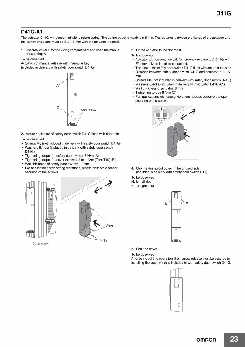
D41G-A1The actuator D41G-A1 is mounted with a return spring. The spring travel is maximum 5 mm. The distance between the flange of the actuator and the switch enclosure must be 5 ± 1.5 mm with the actuator inserted.
1. Unscrew cover C for the wiring compartment and open the manual release flap A.
To be observedActuation of manual release with triangular key(included in delivery with safety door switch D41G)
2. Mount enclosure of safety door switch D41G flush with doorpost.
To be observed• Screws M6 (not included in delivery with safety door switch D41G)• Washers 6.4-dia (included in delivery with safety door switch
D41G)• Tightening torque for safety door switch: 8 N•m (A)• Tightening torque for cover screw: 0.7 to 1 N•m (Torx T10) (B)• Wall thickness of safety door switch: 19 mm• For applications with strong vibrations, please observe a proper
securing of the screws
3. Fit the actuator to the doorpost.
To be observed• Actuator with emergency exit (emergency release tab) D41G-A1-
E0 may only be installed concealed.• Top side of the safety door switch D41G flush with actuator top side• Distance between safety door switch D41G and actuator: 5 ± 1.5
mm• Screws M6 (not included in delivery with safety door switch D41G)• Washers 6.4-dia (included in delivery with actuator D41G-A1)• Wall thickness of actuator: 8 mm• Tightening torque 8 N·m (C)• For applications with strong vibrations, please observe a proper
securing of the screws
4. Clip the dust-proof cover in the unused side. (included in delivery with safety door switch D41)
To be observedM: for left doorN: for right door
5. Seal the cover.
To be observedAfter being put into operation, the manual release must be secured by installing the seal, which is included in with safety door switch D41G.
A
C
GNRDYE
Cover screw
•
•
•
19
GNRDYE
Cover screw
(A)
(B)
5 ±1.5
GNRDYE
N M
D41G
24
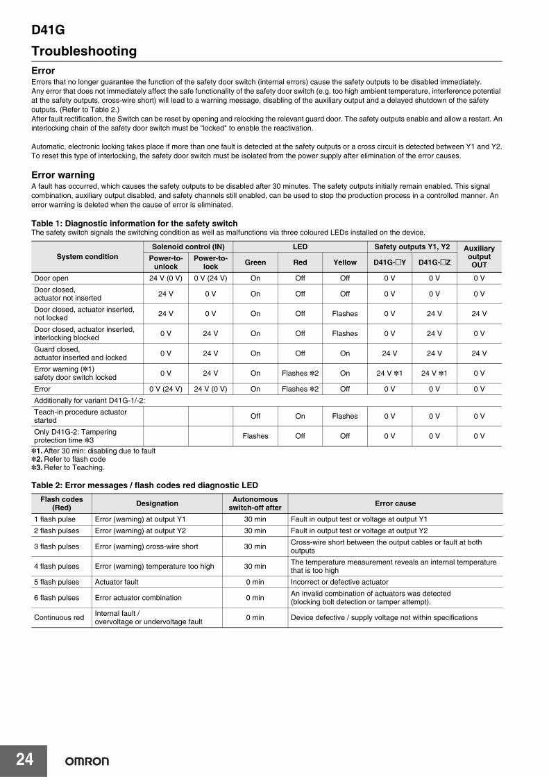
TroubleshootingErrorErrors that no longer guarantee the function of the safety door switch (internal errors) cause the safety outputs to be disabled immediately.Any error that does not immediately affect the safe functionality of the safety door switch (e.g. too high ambient temperature, interference potential at the safety outputs, cross-wire short) will lead to a warning message, disabling of the auxiliary output and a delayed shutdown of the safety outputs. (Refer to Table 2.)After fault rectification, the Switch can be reset by opening and relocking the relevant guard door. The safety outputs enable and allow a restart. Aninterlocking chain of the safety door switch must be "locked" to enable the reactivation.
Automatic, electronic locking takes place if more than one fault is detected at the safety outputs or a cross circuit is detected between Y1 and Y2.To reset this type of interlocking, the safety door switch must be isolated from the power supply after elimination of the error causes.
Error warningA fault has occurred, which causes the safety outputs to be disabled after 30 minutes. The safety outputs initially remain enabled. This signal combination, auxiliary output disabled, and safety channels still enabled, can be used to stop the production process in a controlled manner. An error warning is deleted when the cause of error is eliminated.
Table 1: Diagnostic information for the safety switchThe safety switch signals the switching condition as well as malfunctions via three coloured LEDs installed on the device.
*1. After 30 min: disabling due to fault*2. Refer to flash code*3. Refer to Teaching.
Table 2: Error messages / flash codes red diagnostic LED
System conditionSolenoid control (IN) LED Safety outputs Y1, Y2 Auxiliary
output OUT
Power-to-unlock
Power-to-lock Green Red Yellow D41G-@Y D41G-@Z
Door open 24 V (0 V) 0 V (24 V) On Off Off 0 V 0 V 0 V
Door closed, actuator not inserted 24 V 0 V On Off Off 0 V 0 V 0 V
Door closed, actuator inserted, not locked 24 V 0 V On Off Flashes 0 V 24 V 24 V
Door closed, actuator inserted, interlocking blocked 0 V 24 V On Off Flashes 0 V 24 V 0 V
Guard closed,actuator inserted and locked 0 V 24 V On Off On 24 V 24 V 24 V
Error warning (*1)safety door switch locked 0 V 24 V On Flashes *2 On 24 V *1 24 V *1 0 V
Error 0 V (24 V) 24 V (0 V) On Flashes *2 Off 0 V 0 V 0 V
Additionally for variant D41G-1/-2:
Teach-in procedure actuator started Off On Flashes 0 V 0 V 0 V
Only D41G-2: Tampering protection time *3 Flashes Off Off 0 V 0 V 0 V
Flash codes(Red) Designation Autonomous
switch-off after Error cause
1 flash pulse Error (warning) at output Y1 30 min Fault in output test or voltage at output Y1
2 flash pulses Error (warning) at output Y2 30 min Fault in output test or voltage at output Y2
3 flash pulses Error (warning) cross-wire short 30 min Cross-wire short between the output cables or fault at both outputs
4 flash pulses Error (warning) temperature too high 30 min The temperature measurement reveals an internal temperature that is too high
5 flash pulses Actuator fault 0 min Incorrect or defective actuator
6 flash pulses Error actuator combination 0 min An invalid combination of actuators was detected (blocking bolt detection or tamper attempt).
Continuous red Internal fault / overvoltage or undervoltage fault 0 min Device defective / supply voltage not within specifications
D41G
25
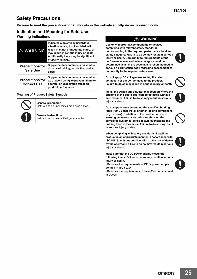
Safety PrecautionsBe sure to read the precautions for all models in the website at: http://www.ia.omron.com/.
Indication and Meaning for Safe UseWarning Indications
Meaning of Product Safety Symbols
Use only appropriate components or devices complying with relevant safety standards corresponding to the required performance level and safety category. Failure to do so may result in serious injury or death. Conformity to requirements of the performance level and safety category must be determined as an entire system. It is recommended to consult a certification body regarding assessment of conformity to the required safety level.
Do not apply DC voltages exceeding the rated voltages, nor any AC voltages to the product. Failure to do so may result in serious injury or death.
Install the switch and actuator in a position where the opening of the guard door can be detected within a safe distance. Failure to do so may result in serious injury or death.
Do not apply force exceeding the specified holding force (Fzh). Either install another locking component (e.g., a hook) in addition to the product, or use a warning measures or an indicator showing the controlled system is locked to avid overloading the holding force in lock mode. Failure to do so may result in serious injury or death.
When complying with safety standards, install the product in an appropriate manner in accordance with ISO 14119, with due consideration of the risk of defeat by the operator. Failure to do so may result in serious injury or death.
Make sure that the DC power supply meets the following items. Failure to do so may result in serious injury or death.- Satisfies the requirements of PELV power supply defined in IEC 60204-1.- Satisfies the requirements of class 2 circuits defined in UL508.
WARNING
Indicates a potentially hazardous situation which, if not avoided, will result in minor or moderate injury, or may result in serious injury or death. Additionally there may be significant property damage.
Precautions for Safe Use
Supplementary comments on what to do or avoid doing, to use the product safely.
Precautions for Correct Use
Supplementary comments on what to do or avoid doing, to prevent failure to operate, or undesirable effect on product performance.
General prohibitionInstructions on unspecified prohibited action.
General instructionsInstructions on unspecified general action.
WARNING
D41G
26
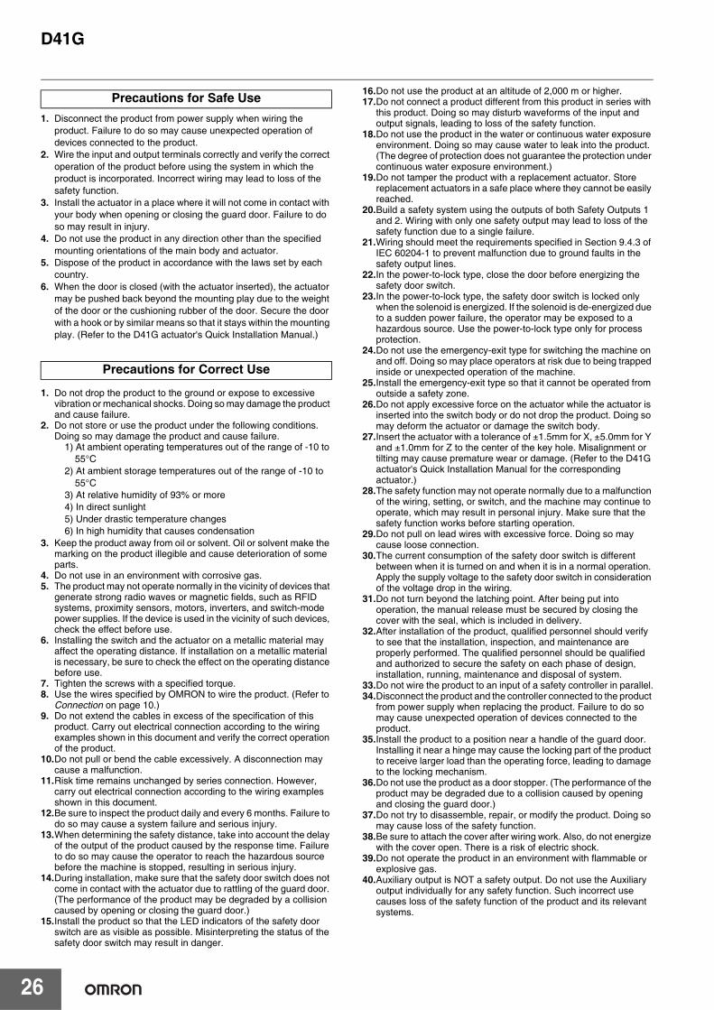
1. Disconnect the product from power supply when wiring the product. Failure to do so may cause unexpected operation of devices connected to the product.
2. Wire the input and output terminals correctly and verify the correct operation of the product before using the system in which the product is incorporated. Incorrect wiring may lead to loss of the safety function.
3. Install the actuator in a place where it will not come in contact with your body when opening or closing the guard door. Failure to do so may result in injury.
4. Do not use the product in any direction other than the specified mounting orientations of the main body and actuator.
5. Dispose of the product in accordance with the laws set by each country.
6. When the door is closed (with the actuator inserted), the actuator may be pushed back beyond the mounting play due to the weight of the door or the cushioning rubber of the door. Secure the door with a hook or by similar means so that it stays within the mounting play. (Refer to the D41G actuator's Quick Installation Manual.)
1. Do not drop the product to the ground or expose to excessive vibration or mechanical shocks. Doing so may damage the product and cause failure.
2. Do not store or use the product under the following conditions. Doing so may damage the product and cause failure.
1) At ambient operating temperatures out of the range of -10 to 55°C
2) At ambient storage temperatures out of the range of -10 to 55°C
3) At relative humidity of 93% or more4) In direct sunlight5) Under drastic temperature changes6) In high humidity that causes condensation
3. Keep the product away from oil or solvent. Oil or solvent make the marking on the product illegible and cause deterioration of some parts.
4. Do not use in an environment with corrosive gas.5. The product may not operate normally in the vicinity of devices that
generate strong radio waves or magnetic fields, such as RFID systems, proximity sensors, motors, inverters, and switch-mode power supplies. If the device is used in the vicinity of such devices, check the effect before use.
6. Installing the switch and the actuator on a metallic material may affect the operating distance. If installation on a metallic material is necessary, be sure to check the effect on the operating distance before use.
7. Tighten the screws with a specified torque.8. Use the wires specified by OMRON to wire the product. (Refer to
Connection on page 10.)9. Do not extend the cables in excess of the specification of this
product. Carry out electrical connection according to the wiring examples shown in this document and verify the correct operation of the product.
10.Do not pull or bend the cable excessively. A disconnection may cause a malfunction.
11.Risk time remains unchanged by series connection. However, carry out electrical connection according to the wiring examples shown in this document.
12.Be sure to inspect the product daily and every 6 months. Failure to do so may cause a system failure and serious injury.
13.When determining the safety distance, take into account the delay of the output of the product caused by the response time. Failure to do so may cause the operator to reach the hazardous source before the machine is stopped, resulting in serious injury.
14.During installation, make sure that the safety door switch does not come in contact with the actuator due to rattling of the guard door. (The performance of the product may be degraded by a collision caused by opening or closing the guard door.)
15.Install the product so that the LED indicators of the safety door switch are as visible as possible. Misinterpreting the status of the safety door switch may result in danger.
16.Do not use the product at an altitude of 2,000 m or higher.17.Do not connect a product different from this product in series with
this product. Doing so may disturb waveforms of the input and output signals, leading to loss of the safety function.
18.Do not use the product in the water or continuous water exposure environment. Doing so may cause water to leak into the product. (The degree of protection does not guarantee the protection under continuous water exposure environment.)
19.Do not tamper the product with a replacement actuator. Store replacement actuators in a safe place where they cannot be easily reached.
20.Build a safety system using the outputs of both Safety Outputs 1 and 2. Wiring with only one safety output may lead to loss of the safety function due to a single failure.
21.Wiring should meet the requirements specified in Section 9.4.3 of IEC 60204-1 to prevent malfunction due to ground faults in the safety output lines.
22.In the power-to-lock type, close the door before energizing the safety door switch.
23.In the power-to-lock type, the safety door switch is locked only when the solenoid is energized. If the solenoid is de-energized due to a sudden power failure, the operator may be exposed to a hazardous source. Use the power-to-lock type only for process protection.
24.Do not use the emergency-exit type for switching the machine on and off. Doing so may place operators at risk due to being trapped inside or unexpected operation of the machine.
25.Install the emergency-exit type so that it cannot be operated from outside a safety zone.
26.Do not apply excessive force on the actuator while the actuator is inserted into the switch body or do not drop the product. Doing so may deform the actuator or damage the switch body.
27.Insert the actuator with a tolerance of ±1.5mm for X, ±5.0mm for Y and ±1.0mm for Z to the center of the key hole. Misalignment or tilting may cause premature wear or damage. (Refer to the D41G actuator's Quick Installation Manual for the corresponding actuator.)
28.The safety function may not operate normally due to a malfunction of the wiring, setting, or switch, and the machine may continue to operate, which may result in personal injury. Make sure that the safety function works before starting operation.
29.Do not pull on lead wires with excessive force. Doing so may cause loose connection.
30.The current consumption of the safety door switch is different between when it is turned on and when it is in a normal operation. Apply the supply voltage to the safety door switch in consideration of the voltage drop in the wiring.
31.Do not turn beyond the latching point. After being put into operation, the manual release must be secured by closing the cover with the seal, which is included in delivery.
32.After installation of the product, qualified personnel should verify to see that the installation, inspection, and maintenance are properly performed. The qualified personnel should be qualified and authorized to secure the safety on each phase of design, installation, running, maintenance and disposal of system.
33.Do not wire the product to an input of a safety controller in parallel.34.Disconnect the product and the controller connected to the product
from power supply when replacing the product. Failure to do so may cause unexpected operation of devices connected to the product.
35.Install the product to a position near a handle of the guard door. Installing it near a hinge may cause the locking part of the product to receive larger load than the operating force, leading to damage to the locking mechanism.
36.Do not use the product as a door stopper. (The performance of the product may be degraded due to a collision caused by opening and closing the guard door.)
37.Do not try to disassemble, repair, or modify the product. Doing so may cause loss of the safety function.
38.Be sure to attach the cover after wiring work. Also, do not energize with the cover open. There is a risk of electric shock.
39.Do not operate the product in an environment with flammable or explosive gas.
40.Auxiliary output is NOT a safety output. Do not use the Auxiliary output individually for any safety function. Such incorrect use causes loss of the safety function of the product and its relevant systems.
Precautions for Safe Use
Precautions for Correct Use
D41G
27
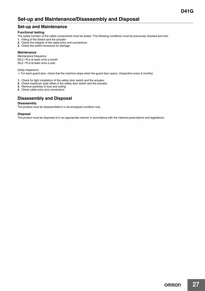
Set-up and Maintenance/Disassembly and DisposalSet-up and MaintenanceFunctional testingThe safety function of the safety components must be tested. The following conditions must be previously checked and met:1. Fitting of the Switch and the actuator2. Check the integrity of the cable entry and connections3. Check the switch enclosure for damage
MaintenanceMaintenance frequencySIL3 / PLe at least once a monthSIL2 / PLd at least once a year
(Daily inspection)• For each guard door, check that the machine stops when the guard door opens. (Inspection every 6 months)
1. Check for tight installation of the safety door switch and the actuator.2. Check maximum axial offset of the safety door switch and the actuator.3. Remove particles of dust and soiling4. Check cable entry and connections
Disassembly and DisposalDisassemblyThe product must be disassembled in a de-energized condition only.
DisposalThe product must be disposed of in an appropriate manner in accordance with the national prescriptions and legislations.

MEMO
28
Terms and Conditions AgreementRead and understand this catalog.
Please read and understand this catalog before purchasing the products. Please consult your OMRON representative if you have any questions or comments.
Warranties.(a) Exclusive Warranty. Omron’s exclusive warranty is that the Products will be free from defects in materials and workmanship
for a period of twelve months from the date of sale by Omron (or such other period expressed in writing by Omron). Omron disclaims all other warranties, express or implied.
(b) Limitations. OMRON MAKES NO WARRANTY OR REPRESENTATION, EXPRESS OR IMPLIED, ABOUT NON-INFRINGEMENT, MERCHANTABILITY OR FITNESS FOR A PARTICULAR PURPOSE OF THE PRODUCTS. BUYER ACKNOWLEDGES THAT IT ALONE HAS DETERMINED THAT THE PRODUCTS WILL SUITABLY MEET THE REQUIREMENTS OF THEIR INTENDED USE.
Omron further disclaims all warranties and responsibility of any type for claims or expenses based on infringement by the Products or otherwise of any intellectual property right. (c) Buyer Remedy. Omron’s sole obligation hereunder shall be, at Omron’s election, to (i) replace (in the form originally shipped with Buyer responsible for labor charges for removal or replacement thereof) the non-complying Product, (ii) repair the non-complying Product, or (iii) repay or credit Buyer an amount equal to the purchase price of the non-complying Product; provided that in no event shall Omron be responsible for warranty, repair, indemnity or any other claims or expenses regarding the Products unless Omron’s analysis confirms that the Products were properly handled, stored, installed and maintained and not subject to contamination, abuse, misuse or inappropriate modification. Return of any Products by Buyer must be approved in writing by Omron before shipment. Omron Companies shall not be liable for the suitability or unsuitability or the results from the use of Products in combination with any electrical or electronic components, circuits, system assemblies or any other materials or substances or environments. Any advice, recommendations or information given orally or in writing, are not to be construed as an amendment or addition to the above warranty.
See http://www.omron.com/global/ or contact your Omron representative for published information.
Limitation on Liability; Etc.OMRON COMPANIES SHALL NOT BE LIABLE FOR SPECIAL, INDIRECT, INCIDENTAL, OR CONSEQUENTIAL DAMAGES, LOSS OF PROFITS OR PRODUCTION OR COMMERCIAL LOSS IN ANY WAY CONNECTED WITH THE PRODUCTS, WHETHER SUCH CLAIM IS BASED IN CONTRACT, WARRANTY, NEGLIGENCE OR STRICT LIABILITY.
Further, in no event shall liability of Omron Companies exceed the individual price of the Product on which liability is asserted.
Suitability of Use.Omron Companies shall not be responsible for conformity with any standards, codes or regulations which apply to the combination of the Product in the Buyer’s application or use of the Product. At Buyer’s request, Omron will provide applicable third party certification documents identifying ratings and limitations of use which apply to the Product. This information by itself is not sufficient for a complete determination of the suitability of the Product in combination with the end product, machine, system, or other application or use. Buyer shall be solely responsible for determining appropriateness of the particular Product with respect to Buyer’s application, product or system. Buyer shall take application responsibility in all cases.
NEVER USE THE PRODUCT FOR AN APPLICATION INVOLVING SERIOUS RISK TO LIFE OR PROPERTY OR IN LARGE QUANTITIES WITHOUT ENSURING THAT THE SYSTEM AS A WHOLE HAS BEEN DESIGNED TO ADDRESS THE RISKS, AND THAT THE OMRON PRODUCT(S) IS PROPERLY RATED AND INSTALLED FOR THE INTENDED USE WITHIN THE OVERALL EQUIPMENT OR SYSTEM.
Programmable Products.Omron Companies shall not be responsible for the user’s programming of a programmable Product, or any consequence thereof.
Performance Data.Data presented in Omron Company websites, catalogs and other materials is provided as a guide for the user in determining suitability and does not constitute a warranty. It may represent the result of Omron’s test conditions, and the user must correlate it to actual application requirements. Actual performance is subject to the Omron’s Warranty and Limitations of Liability.
Change in Specifications.Product specifications and accessories may be changed at any time based on improvements and other reasons. It is our practice to change part numbers when published ratings or features are changed, or when significant construction changes are made. However, some specifications of the Product may be changed without any notice. When in doubt, special part numbers may be assigned to fix or establish key specifications for your application. Please consult with your Omron’s representative at any time to confirm actual specifications of purchased Product.
Errors and Omissions.Information presented by Omron Companies has been checked and is believed to be accurate; however, no responsibility is assumed for clerical, typographical or proofreading errors or omissions.
Authorized Distributor:
In the interest of product improvement, specifications are subject to change without notice.
Cat. No. F114-E1-02 0621 (0321)
© OMRON Corporation 2021 All Rights Reserved.
OMRON Corporation Industrial Automation Company
OMRON ELECTRONICS LLC2895 Greenspoint Parkway, Suite 200 Hoffman Estates, IL 60169 U.S.A.Tel: (1) 847-843-7900/Fax: (1) 847-843-7787
Regional HeadquartersOMRON EUROPE B.V.Wegalaan 67-69, 2132 JD HoofddorpThe NetherlandsTel: (31)2356-81-300/Fax: (31)2356-81-388
Contact: www.ia.omron.comKyoto, JAPAN
OMRON ASIA PACIFIC PTE. LTD.No. 438A Alexandra Road # 05-05/08 (Lobby 2), Alexandra Technopark, Singapore 119967Tel: (65) 6835-3011/Fax: (65) 6835-2711
OMRON (CHINA) CO., LTD.Room 2211, Bank of China Tower, 200 Yin Cheng Zhong Road, PuDong New Area, Shanghai, 200120, ChinaTel: (86) 21-5037-2222/Fax: (86) 21-5037-2200
High-Coded Safety Door Switch
1
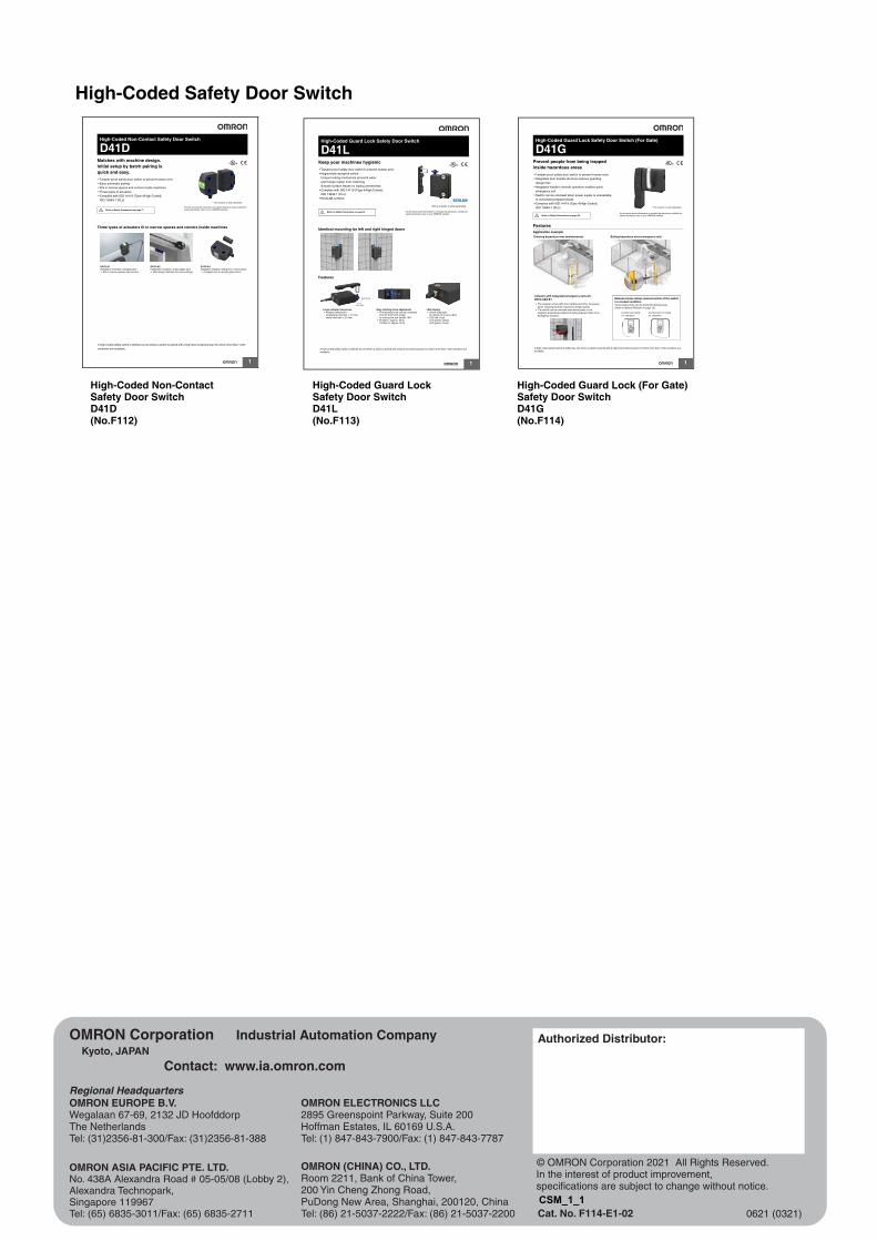
High-Coded Non-Contact Safety Door Switch
D41DMatches with machine design.Initial setup by batch pairing is quick and easy.� Tamper-proof safety door switch to prevent human error� Easy automatic pairing� Fits in narrow spaces and corners inside machines� Three types of actuators� Complies with ISO 14119 (Type 4/High Coded),
ISO 13849-1 (PLe)
Three types of actuators fit in narrow spaces and corners inside machines
Refer to Safety Precautions on page 17
D41D-A1Installation example: swinging door� Fits in narrow spaces and corners
D41D-A2Installation example: acrylic glass door� Flat design matches the surroundings
D41D-A3Installation example: sliding door, narrow space� Compact size for acrylic glass doors
For the most recent information on models that have been certified for safety standards, refer to your OMRON website.
* The actuator is sold separately.
A high-coded safety switch is defined as one where a switch is paired with a high level coded actuator for which more than 1,000
variations are available.
1
High-Coded Guard Lock Safety Door Switch
D41LKeep your machines hygienic� Tamper-proof safety door switch to prevent human error� Hygienically designed switch
Unique locking mechanism prevents water and foreign matter from collectingSmooth surface leaves no wiping unevenness
� Complies with ISO 14119 (Type 4/High Coded), ISO 13849-1 (PLe)
� ECOLAB certified
Identical mounting for left and right hinged doors
Features
Refer to Safety Precautions on page18
Large actuator tolerances� Actuator tolerance in
longitudinal direction ± 3.5 mm,lateral direction ± 2.0 mm
Easy latching force adjustment� The latching force can be increased
from 25 N to 50 N simply by turning the star handle 180°.
� Position I: approx. 25 N,Position II: approx. 50 N
LED display� Smart diagnostic
by means of 3-color LED's� LED red: Fault
LED yellow: StatusLED green: Power
For the most recent information on models that have been certified for safety standards, refer to your OMRON website.
* The actuator is sold separately.
±3.5 mm
±2.0 mm
A high-coded safety switch is defined as one where a switch is paired with a high level coded actuator for which more than 1,000 variations are available.
1
High-Coded Guard Lock Safety Door Switch (For Gate)
D41GPrevent people from being trapped inside hazardous areas� Tamper-proof safety door switch to prevent human error� Integrated door handle structure reduces guarding
design time� Integrated handle's smooth operation enables quick
emergency exit� Switch can be unlocked when power supply is unavailable
to avoid being trapped inside� Complies with ISO 14119 (Type 4/High Coded),
ISO 13849-1 (PLe)
FeaturesApplication example
Refer to Safety Precautions on page 25For the most recent information on models that have been certified for safety standards, refer to your OMRON website.
* The actuator is sold separately.
Entering hazardous area (maintenance) Exiting hazardous area (emergency exit)
Actuator with integrated emergency exit unitD41G-A2@@-E1
� The actuator comes with door handles and other necessary parts, reducing the time required to design guards.
� The switch can be unlocked even when power is not supplied, preventing people from being trapped inside in an emergency situation.
Manual release allows manual unlock of the switch in a locked conditionUnnecessary locks can be prevented during setup.(Refer to Manual Release on page 13.)
Component readyfor operation
Component not readyfor operation
A high-coded safety switch is defined as one where a switch is paired with a high level coded actuator for which more than 1,000 variations are available.
High-Coded Non-ContactSafety Door SwitchD41D(No.F112)
High-Coded Guard Lock Safety Door SwitchD41L(No.F113)
High-Coded Guard Lock (For Gate) Safety Door SwitchD41G(No.F114)
CSM_1_1


![Guard Lock Safety-door Switch D4BL - Mouser Electronics1]-190508.pdf · K3 and K4 (NC) K3 and K4 (NO) KM1 and KM2 (NC) KM1 and KM2 (NO) Operation instruction Lock release signal Lock](https://img.pdfslide.us/doc/110x75/5c9dddbe88c993cb368ba3c5/guard-lock-safety-door-switch-d4bl-mouser-1-190508pdf-k3-and-k4-nc-k3.jpg)