Embed Size (px)
Citation preview
(c)2000 American Institute of Aeronautics & Astronautics or Published with Permission of Author(s) and/or Author(s)' Sponsoring Organization.
AIAA Guidance, Navigation, andControl Conference and Exhibit14-17 August 2000 Denver, CO AOO-37046 AIAA-2000-4057
HIERARCHICAL CONTROL SYSTEM SYNTHESISFOR ROTORCRAFT-BASED UNMANNED AERIAL VEHICLES
David Hyunchul Shim*, Hyoun Jin Kirn*, Shankar Sastry**
ABSTRACT
This paper introduces the development of multiplenumber of Unmanned Arial Vehicle (UAV) systemas a part of BErkeley AeRobot (BEAR) project,highlighting the recent achievements in the designand implementation of rotorcraft-based UAV(RUAV) control system. Based on the experimentalflight data, linear system model valid near hovercondition is found by applying time-domainnumerical methods to experimental flight data. Theacquired linear model is used to design feedbackcontroller consisting of inner-loop attitude feedbackcontrol, mid-loop velocity feedback control and theouter-loop position control. The proposed vehicle-level controller is implemented and tested inBerkeley UAV, Ursa Magna 2, and shows superiorhovering performance. The vehicle level controller isintegrated with higher-level control using a scriptlanguage framework to command UAV.
1. Introduction
The rapid development of the sensor, communicationand control technology in the last few decades hasmade autonomous vehicles smaller and morepowerful. And the need to alleviate the actual humanparticipation in order to save human efforts and avoidhazards has been ever increasing in numerous fields.As a result, autonomous vehicles are about to becomepart of reality in many applications.
BErkeley AeRobot project aims to organize multiplenumber of autonomous agents into integrated andintelligent systems with reduced cognition andcontrol complexity, fault-tolerance, adaptivity to
'Graduate Students, Department of MechanicalEngineering, University of California at Berkeley**Professor, Department of Electrical Engineeringand Computer Science, University of California atBerkeley{hcshim,jin,sastry}@robotics.eecs.berkeley.eduCopyright © 2000 by David Hyunchul Shim.Published by the American Institute ofAeronautics and Astronautics Inc. withpermission.
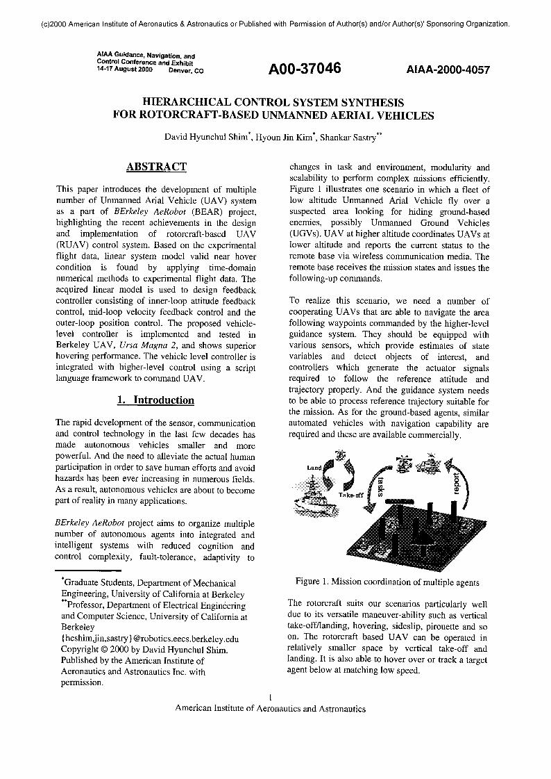
changes in task and environment, modularity andscalability to perform complex missions efficiently.Figure 1 illustrates one scenario in which a fleet oflow altitude Unmanned Arial Vehicle fly over asuspected area looking for hiding ground-basedenemies, possibly Unmanned Ground Vehicles(UGVs). UAV at higher altitude coordinates UAVs atlower altitude and reports the current status to theremote base via wireless communication media. Theremote base receives the mission states and issues thefollowing-up commands.
To realize this scenario, we need a number ofcooperating UAVs that are able to navigate the areafollowing waypoints commanded by the higher-levelguidance system. They should be equipped withvarious sensors, which provide estimates of statevariables and detect objects of interest, andcontrollers which generate the actuator signalsrequired to follow the reference attitude andtrajectory properly. And the guidance system needsto be able to process reference trajectory suitable forthe mission. As for the ground-based agents, similarautomated vehicles with navigation capability arerequired and these are available commercially.
Figure 1. Mission coordination of multiple agents
The rotorcraft suits our scenarios particularly welldue to its versatile maneuver-ability such as verticaltake-off/landing, hovering, sideslip, pirouette and soon. The rotorcraft based UAV can be operated inrelatively smaller space by vertical take-off andlanding. It is also able to hover over or track a targetagent below at matching low speed.
1American Institute of Aeronautics and Astronautics
(c)2000 American Institute of Aeronautics & Astronautics or Published with Permission of Author(s) and/or Author(s)' Sponsoring Organization.
Compared with the mission-level guidance tasks, theactual UAV navigation and control problem is notfully investigated and the diverse research activitiesare ongoing[2,3,4,5,6]. One of the daunting tasks inconstructing a UAV system is to obtain high fidelitymodel to design flight controllers upon. Thetraditional approach of borrowing the modeldeveloped for full-size helicopters often fails toaccount for the unique dynamics of RUAVs, whichare commonly equipped with the servorotor system.Recently, Mettler[2] suggested a very effective modelto account for the dynamics of servorotor. In thisresearch, this model is adopted for the identificationof the hovering and instead of frequency-domainidentification, time-domain method is applied. Theobtained model is used for multi-loop classicalhovering control design and full-model linear robustcontrol synthesis.
Vehicle Control Language(VCL) is also proposed inthis paper as an application and development tool forRUAV systems. This script language system,operating in a hierarchical client-server environment,integrates the vehicle-level control and the higher-level motion command.
The organization of the paper is as follows.Hierarchical architecture and configuration ofBerkeley UAV test bed system are explained in Sec.II. In Sec. Ill, we present the dynamic modelidentified from Berkeley RUAVs, highlighting theeffect of servorotor. In Sec. IV, we discuss how wedesign stabilizing control law and present theexperiment results. In Sec V, the novel approach ofVCL is introduced and examples are given.
2. Berkeley UAV System Architecture
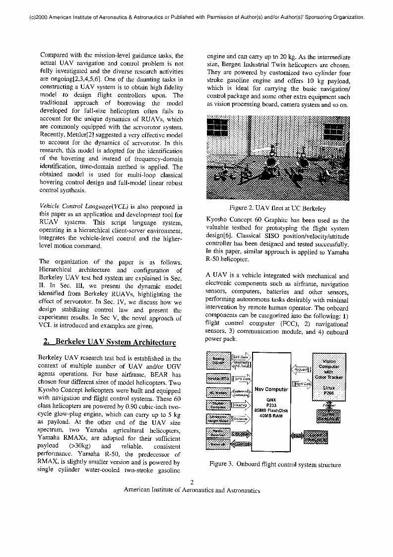
Berkeley UAV research test bed is established in thecontext of multiple number of UAV and/or UGVagents operations. For base airframe, BEAR haschosen four different sizes of model helicopters. TwoKyosho Concept helicopters were built and equippedwith navigation and flight control systems. These 60class helicopters are powered by 0.90 cubic-inch two-cycle glow-plug engine, which can carry up to 5 kgas payload. At the other end of the UAV sizespectrum, two Yamaha agricultural helicopters,Yamaha RMAXs, are adopted for their sufficientpayload (>30kg) and reliable, consistentperformance. Yamaha R-50, the predecessor ofRMAX, is slightly smaller version and is powered bysingle cylinder water-cooled two-stroke gasoline
engine and can carry up to 20 kg. As the intermediatesize, Bergen Industrial Twin helicopters are chosen.They are powered by customized two cylinder fourstroke gasoline engine and offers 10 kg payload,which is ideal for carrying the basic navigation/control package and some other extra equipment suchas vision processing board, camera system and so on.
Figure 2. UAV fleet at UC Berkeley
Kyosho Concept 60 Graphite has been used as thevaluable testbed for prototyping the flight systemdesign[6]. Classical SISO position/velocity/attitudecontroller has been designed and tested successfully.In this paper, similar approach is applied to YamahaR-50 helicopter.
A UAV is a vehicle integrated with mechanical andelectronic components such as airframe, navigationsensors, computers, batteries and other sensors,performing autonomous tasks desirably with minimalintervention by remote human operator. The onboardcomponents can be categorized into the following: 1)flight control computer (FCC), 2) navigationalsensors, 3) communication module, and 4) onboardpower pack.
Nav Computer
QNXP233
85MB Flash Disk40MB RAM
VisionComputer
vitttiCoJor thicker
LinuxP266
Figure 3. Onboard flight control system structure
American Institute of Aeronautics and Astronautics
(c)2000 American Institute of Aeronautics & Astronautics or Published with Permission of Author(s) and/or Author(s)1 Sponsoring Organization.
Table 1. Berkeley UAV physical specificationName
KyoshoConcept 60
BergenIndustrial Twin
Yamaha R-50
Yamaha RMAX
Length
1.4m
1.8m
3.5m
3.63m
Height
0.47m
0.6m
1.08m
1. 2m
Weight9.3kg
(4.5kg+4.8kgavionics)
7kg dry weight
54kg(44kg+10kg
avionics)
60kg dry weight
Engine
OS FX91 2.8bhp
Twin GenoaGasoline engine
Water cooled2stroke 1 cylinder
gasoline engine
Water cooled2 stroke 2 cylinder
gasoline engine
AutonomyBoeing DQINovAtel RT-2MediaGX233
N/A
Boeing DQINovAtel RT-2Pentium2334 ultrasonic altimeterDigital compassVision processor
N/A
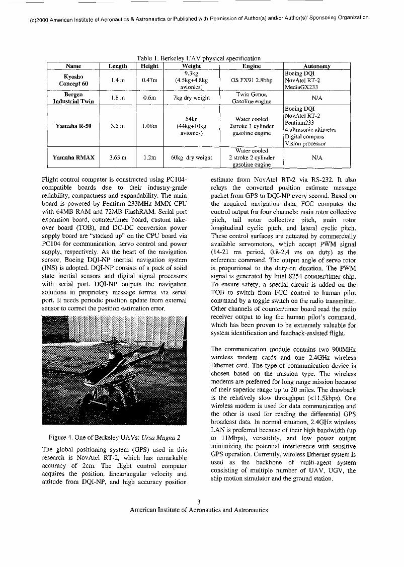
Flight control computer is constructed using PC 104-compatible boards due to their industry-gradereliability, compactness and expandability. The mainboard is powered by Pentium 233MHz MMX CPUwith 64MB RAM and 72MB FlashRAM. Serial portexpansion board, counter/timer board, custom take-over board (TOB), and DC-DC conversion powersupply board are "stacked up" on the CPU board viaPC 104 for communication, servo control and powersupply, respectively. As the heart of the navigationsensor, Boeing DQI-NP inertial navigation system(INS) is adopted. DQI-NP consists of a pack of solidstate inertial sensors and digital signal processorswith serial port. DQI-NP outputs the navigationsolutions in proprietary message format via serialport. It needs periodic position update from externalsensor to correct the position estimation error.
Figure 4. One of Berkeley UAVs: Ursa Magna 2
The global positioning system (GPS) used in thisresearch is NovAtel RT-2, which has remarkableaccuracy of 2cm. The flight control computeracquires the position, linear/angular velocity andattitude from DQI-NP, and high accuracy position
estimate from NovAtel RT-2 via RS-232. It alsorelays the converted position estimate messagepacket from GPS to DQI-NP every second. Based onthe acquired navigation data, FCC computes thecontrol output for four channels: main rotor collectivepitch, tail rotor collective pitch, main rotorlongitudinal cyclic pitch, and lateral cyclic pitch.These control surfaces are actuated by commerciallyavailable servomotors, which accept PWM signal(14-21 ms period, 0.8-2.4 ms on duty) as thereference command. The output angle of servo rotoris proportional to the duty-on duration. The PWMsignal is generated by Intel 8254 counter/timer chip.To ensure safety, a special circuit is added on theTOB to switch from FCC control to human pilotcommand by a toggle switch on the radio transmitter.Other channels of counter/timer board read the radioreceiver output to log the human pilot's command,which has been proven to be extremely valuable forsystem identification and feedback-assisted flight.
The communication module contains two 900MHzwireless modem cards and one 2.4GHz wirelessEthernet card. The type of communication device ischosen based on the mission type. The wirelessmodems are preferred for long range mission becauseof their superior range up to 20 miles. The drawbackis the relatively slow throughput (<11.5kbps). Onewireless modem is used for data communication andthe other is used for reading the differential GPSbroadcast data. In normal situation, 2.4GHz wirelessLAN is preferred because of their high bandwidth (upto UMbps), versatility, and low power outputminimizing the potential interference with sensitiveGPS operation. Currently, wireless Ethernet system isused as the backbone of multi-agent systemconsisting of multiple number of UAV, UGV, theship motion simulator and the ground station.
American Institute of Aeronautics and Astronautics
(c)2000 American Institute of Aeronautics & Astronautics or Published with Permission of Author(s) and/or Author(s)' Sponsoring Organization.
Ground station consists of a GPS base station and aportable computer connected with a communicationdevice such as wireless modem or wireless Ethernet.Ground station monitors and stores the flight data ofthe UAV and also sends the navigation commandscomprised of vehicle control language as explained inSec. V.
Larger UAVs are equipped with an onboard visionprocessing unit (VPU) and a camera actuated by pan-tilt-zoom platform. VPU can track a target objectwith certain color and computes its coordinate basedon the navigation data received from the onboardFCC via serial link. It can be accessed by itsindependent wireless Ethernet for monitoring anddebugging purposes. VPU serves the vital role forvision-based landing, ground object detection andmap building.
3. System Identification
The acquisition of high fidelity system model oftarget UAV is a crucial step towards the successful
design of high-performance flight control system. Ingeneral, however, it is often a challenging task toperform system identification of a rotorcraft basedUAV system due to its multi-input multi-output(MIMO), nonlinear characteristics, severe noise anddisturbance, and wide flight envelop.
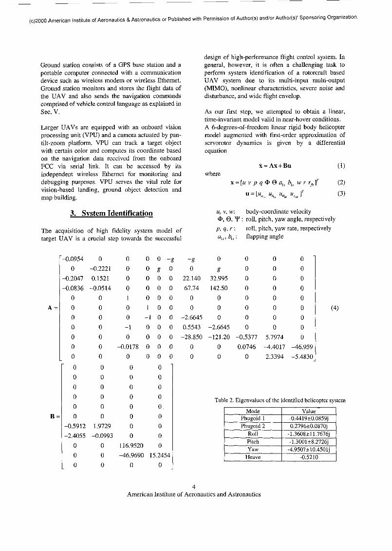
As our first step, we attempted to obtain a linear,time-invariant model valid in near-hover conditions.A 6-degrees-of-freedom linear rigid body helicoptermodel augmented with first-order approximation ofservorotor dynamics is given by a differentialequation
wherex = Ax + Bu
x = [M v p q <I> 0 als bls w ru = [ua u, UH ur ]r
L "„ b,, BM r,,, J
(1)
(2)(3)
u, v, w: body-coordinate velocity<&, 0, *F: roll, pitch, yaw angle, respectivelyp, q, r: roll, pitch, yaw rate, respectivelyals,bls\ flapping angle
A =
B =
"-0.09540
-0.2047-0.0836
0000000000000
-0.5912-2.4055
000
0-0.22210.1521-0.0514
0000000000000
1.9729-0.0993
000
0000100-10
-0.0178000000000
116.9520-46.9690
0
000001-10000
15
0g000000000000000000
-g -8 00 0 £
00
0 22.140 32.995 00 67.74 142.50 00 0 00 0 00 -2.6645 0
000
0 0.5543 -2.6645 00 -28.850 -121.20 -0.53770 0 00 0 0'
24540
00000000
00000000
5.7974 00.0746 -4.4017 -46.959
0 2.3394 -5.4830
Table 2. Eigenvalues of the identified helic
ModePhugoid 1Phugoid 2
RollPitchYaw
Heave
Value-0.4419±0.0.2796±0.(
-1.3608±11-1.3001±8.-4.9507±10
-0.52K
(4)
American Institute of Aeronautics and Astronautics
(c)2000 American Institute of Aeronautics & Astronautics or Published with Permission of Author(s) and/or Author(s)1 Sponsoring Organization.
rft : feedback gyro system state .One candidate model of eleventh order takes the formof Eq. (4) as suggested by Mettler et al [2]. Onedistinction of this model is the explicit account forthe servorotor, which modifies the helicopterdynamics significantly. The most important role ofservorotor is to slow down the roll and pitch responseso that human pilot on the ground can control thehelicopter with a remote controller. Heave dynamicsis approximated by first order quasi-static model.This model yields linear, low-order approximation ofthe nonlinear high-order heave dynamics. For higherbandwidth controllers, the third or fourth order ofmodel containing inflow and flapping dynamicsshould be used [7]. Yaw dynamics is inherentlystable and modeled as first order system withreasonable fidelity. One special feature of the yawdynamics is the built-in feedback action of yaw ratein the loop, which is provided by the built-in rategyro amplifier/mixer. Even though uncompensatedyaw dynamics is stable, the variation of the anti-torque of the main rotor continually perturbs theheading of the helicopter. The yaw rate feedbackcounteracts the torque by compensating the tail rotorcollective pitch and left in the UAV system in case ofmanual flights. The gyro system model suggested byMettler[2] is effective to account for the yawdynamics. One deficiency of the model (4) is theabsence of the cross coupling from yaw to sideslipand roll. It can be additionally parametrized in themodel, but it turned out during the numerical processthat the additional parameters are cumbersome to findbecause they appear as a product of parameters andthe numerical process becomes singular.
Since the model is treated as a linear model, thenonlinearity of helicopter aerodynamics should notbe excited by the excessive amount of control action.Hence, the appropriate design of control input signalsfor flight test is extremely important for theidentification of target flight dynamics. A number ofexperimental flights have been made to collect theflight data and the pilot input at 50Hz sampling rate.The control input consists of the combination offrequency-sweeping and random signals inlongitudinal, lateral, yaw and heave channels in turn.At the first stage, the control in longitudinal andlateral channels are given simultaneously to capturethe coupling between these axes while other channelsare controlled to maintain constant altitude andheading. In the next stage, main rotor collective pitchor tail collective pitch is perturbed. Finally, control
signals are issued in all channels to capture the cross-coupling term.
Before processing the data, the angular rate signalsare filtered by zero-phase noncausal discrete-timefilters to filter out high frequency noise withoutintroducing phase delay. The experiment result isprocessed using time-domain output-errorminimization tool from MatLAB™ SystemIdentification Toolbox™. The prediction errormethod (PEM) is an estimation algorithm, whichseeks to a set of parameters minimizing the quadraticerror between the predicted output and experimentdata[8,9]. It should be noted that this method isextremely sensitive to the initial guess of theparameters and easily trapped in local minima of theparameter hypersurface. To obtain meaningful resultsother than some parameter set that blindly matchesthe time history, the following technique is devised.First, the angular dynamics augmented with rotordynamics is identified using initial guess. Since theangular rate/rotor dynamics is known to be stable andsmall number of parameters are involved, thenumerical solution converges to consistent solutions.Then the horizontal dynamics, i.e., the longitudinaland lateral dynamics with linear velocity terms u andv, are identified while fixing the angular dynamicsparameters. This stage is rather challenging due to theunstable linear velocity dynamics. Shorter length ofexperiment data should be used to avoid theinstability of the predictor and the divergence of theprediction error with the small mismatch of the initialcondition and parameters. The solution is found aftera large number of iterations using the experimentaldata from different time intervals. Separate from thelongitudinal and lateral dynamics, the heave and yawdynamics is identified in similar manner. Theinherent stability of yaw and heave allows niceconvergence of the parameters. Once these twosubsystems are identified, they are combined as thefull-model dynamics and then the cross-couplingterms are estimated. Finally, a small number ofiteration is performed to recalibrate the parameters inthe subsystems.
4. Controller Design and Experiments
Based on the identified model in Sec. 3, stabilizingcontrol law is designed. As our first approach, weemploy single-input, single-output (SISO) controlstructure. Classic control design approach has anumber of advantages such as simple structure,straightforward design process and low computing
American Institute of Aeronautics and Astronautics
(c)2000 American Institute of Aeronautics & Astronautics or Published with Permission of Author(s) and/or Author(s)1 Sponsoring Organization.
load imposed on the FCC. On the contrary, it islimited by a number of disadvantages: it does notprovide a systematic way to account for uncertainty,disturbance and/or noise. Moreover, it has limitedcapability to alleviate the coupling among channels.
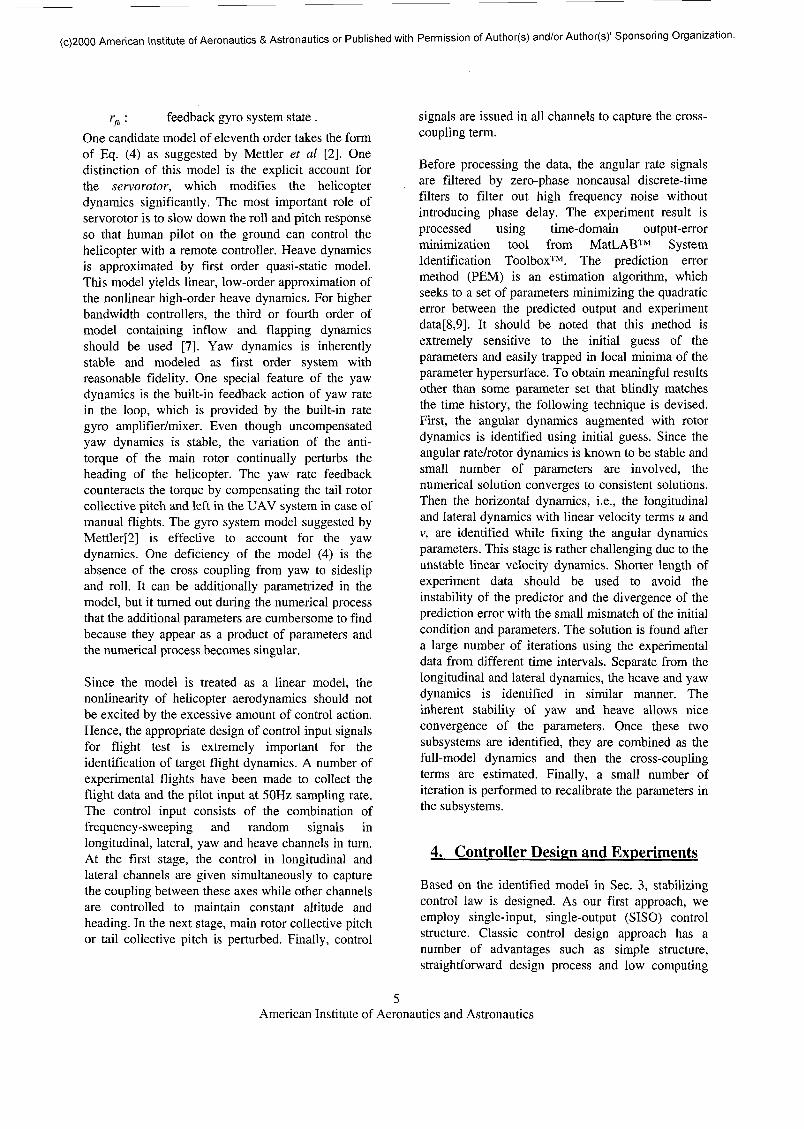
The proposed control system consists of three loops:innermost attitude controller, mid-loop linear velocitycontroller, and the outer loop position controller, asshown in Figure 5.
The attitude dynamics of RUAV with servorotormechanism has a unique dynamics, which issignificantly different from the full-size helicopterwithout servorotor system[l]. The attitude dynamicsof RUAV can be considered marginally stable iftranslational velocities are fixed at zero. On thecontrary, the full-size helicopter without servorotorexhibits unstable attitude dynamics, which must bestabilized by angular feedback. The attitudecontroller proposed in this research only feed backthe deviation of the roll and pitch angles from thetrim condition and does not feed back the noisyangular rates p and q measured by solid state rategyros. This approach yields a controller that issimpler and more robust to mechanical vibration. Theadequate angular feedback gains for roll and pitchchannels are determined to have acceptable responsespeed and damping by using root locus and stepresponse.
Figure 5. The proposed controller architecture usingSISO multi-loop controllers
The translational velocity dynamics of RUAV isalmost identical to that of a full-size helicopter. Thispart of dynamics is unstable even with attitudefeedback and requires velocity feedback. It can bestabilized with velocity feedback with constant gain,which is again found by conventional root locus andstep response method.
For position controller design, the system model (2)is augmented with three parallel integrators, whichintegrate translational velocities of x, y, z direction,respectively. The actual position integration,however, involves the coordinate transformationusing Euler angles, which cannot be described withinlinear equations. Hence, the position control involvesinternal coordinate transformation to compensate forthe heading change. The position gains are found byapplying the similar methods described above to theaugmented RUAV dynamics with velocity andattitude feedback.
Apart from x-y directional dynamics, the vertical andthe heading control require their own controllers.Although vertical and heading dynamics showsconsiderable coupling, conventional SISO controlapproach is maintained. These sub-dynamics showinherently stable response due to the naturalequilibrium of the change of inflow and the generatedlift. The vertical response can be further improved byintroducing artificial damping by negative velocityfeedback. For yaw rate response, the dynamics isalready compensated enough by built-in gyro system.Still, the yaw angle response is marginally stable andthe yaw tracking system can be built by simpleheading error feedback with constant gain in itssimplest form. The proposed controller based on fullydecoupled SISO model is then tested on the fullmodel, investigating the level of coupling when theloop is closed. The simulation showed that the closedloop system shows satisfactory performance.
This simple structure of classical approach enablessimple, but very effective control algorithm. In cruisemode, the velocity and attitude loops are closed forstabilization and tracking. When hovering over acertain spot is required, the outmost loop for positionfeedback is closed along with the inner loops. Thisalgorithm is implemented in FCC and showed thisidea actually works for real situation.
The proposed control algorithm is implemented onthe FCC. FCC is running on QNX real-time operatingsystem. The onboard navigation and control softwarehas two main processes and two auxiliary processesrunning concurrently, interacting with INS, GPS,servos, ultrasonic sensors, and vision computer.Process DQIGPS reads the GPS information andupdates the INS using the GPS position estimate atIHz. Process DQICONT reads in the INSmeasurements at lOOHz. These INS and GPSmeasurements are stored in the shared memory space
American Institute of Aeronautics and Astronautics
(c)2000 American Institute of Aeronautics & Astronautics or Published with Permission of Author(s) and/or Author(s)1 Sponsoring Organization.
accessible to client processes. The control output iscalculated using INS and GPS measurement at 46Hzand then sent to the registers of counter/timer chip,which generates a set of five PWM signals. Theoutput to five servos can be switched from the signalfrom radio receiver or the computer generated PWMsignal transmitted over optoisolators to guaranteestable operation of built-in Yamaha controllers andonboard computer systems.
45 45.2 45.4 45.6 45.8 46
0 50 100 150 0 50 100 150
0 50 100 150 0 50 100 150
0 50 100 150 0 50 100 150
0 50 100 150 0 50 100 150
50 100 150 50 100 150
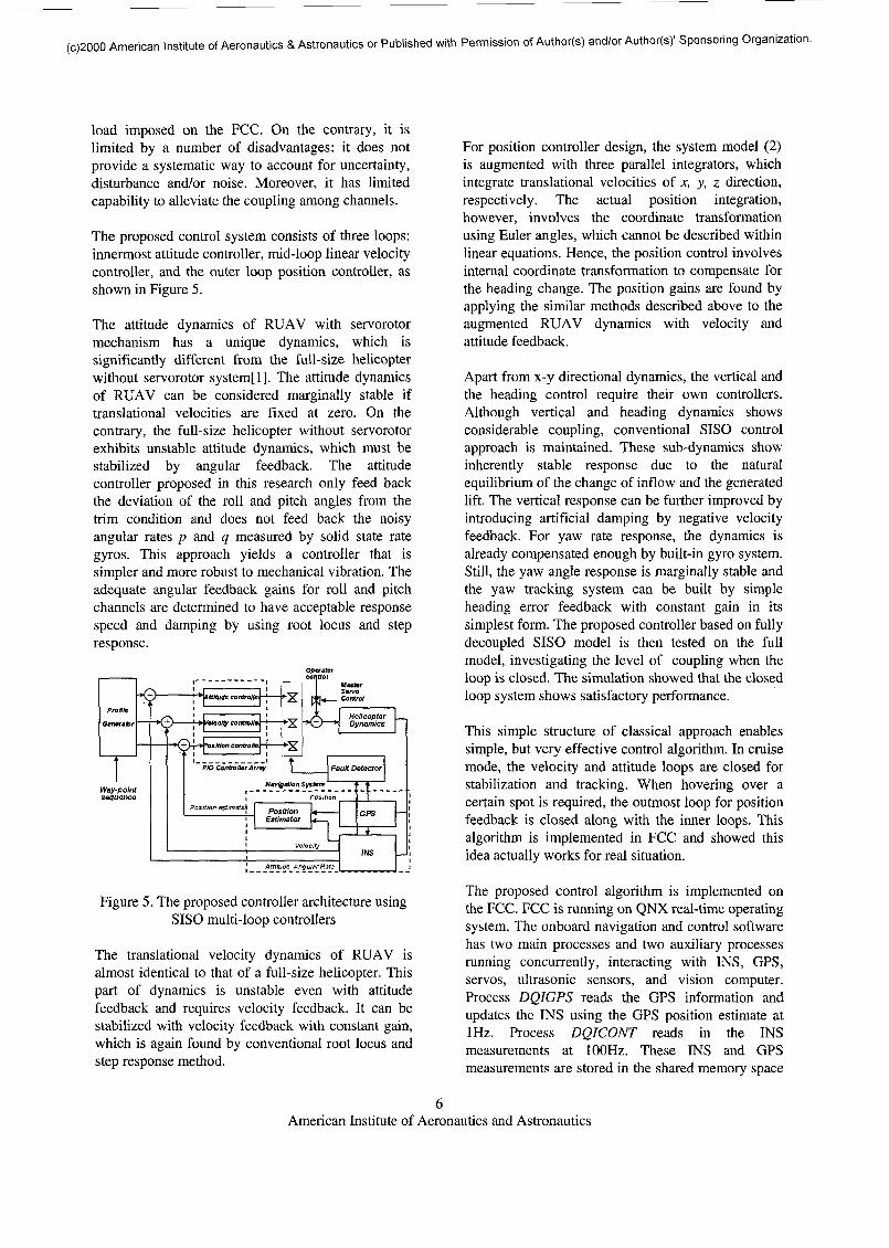
Figure 6. Experiment result of autonomous hovering
A series of experiments has been performed using theproposed controller on Yamaha R-50. Theexperiment is performed as described here: TheRUAV is first placed at the test field, preferably flat
location, and then the flight system and radio/servosystem are turned on. The GPS system automaticallystarts tracking the GPS satellite signals to computethe current location coordinates. The DGPS broadcastare used to achieve the ultimate accuracy of 2cm.Once GPS is completely locked on, the DQI-NPsystem is initialized and sequenced into the fine-alignment mode. During this process, the DQI systemshould be left undisturbed to correctly estimate thescale and bias factors of the six solid state inertialsensors. After these two navigation sensors areinitialized, the engine is started manually and theRPM is quickly brought up to 90 % of the hoveringRPM to avoid any low frequency mechanicalresonance harmful to proper INS/GPS operation.
During the repeated experiments, the attitude/velocitycontroller has shown stable operation even when thehelicopter stays on the ground. Therefore, moreaccurate take-off and landing can be achieved byactivating the attitude/velocity controller even beforethe helicopter takes off from the ground. Whenoperated manually, the pilot engages theattitude/velocity controller using a switch on thetransmitter and then takes the helicopter off from theground. At this time, only steady heave referencecommand is given. Once the helicopter reaches thedesired altitude, the hovering controller, i.e., theposition/velocity/attitude loop controller is activated.
Figure 6 shows the experiment result of hoveringcontroller tested on R-50 UAV. The RUAV showed astable response over two minutes with ±0.5maccuracy in x and y direction. Roll, pitch,translational velocity in x and y directions areregulated very well altogether. The altitude regulationshows rather large variation because the engine wasnot regulated to a constant RPM. A simpleproportional-integral(PI) controller will be added insystem for more stable response.
5. Vehicle Control Language Framework
Once the regulation layer for the vehicle control isdesigned, then supervising control logic should beintegrated with the vehicle regulation layer to guidethe RUAV along the desired trajectory. This layerplays an important role to relay the mission controllayer and the vehicle-level control layer bygenerating appropriate reference trajectories and theninjecting them into the proper controller, which isactivated accordingly depending on the flight statusand the target mode.
American Institute of Aeronautics and Astronautics
(c)2000 American Institute of Aeronautics & Astronautics or Published with Permission of Author(s) and/or Author(s)' Sponsoring Organization.
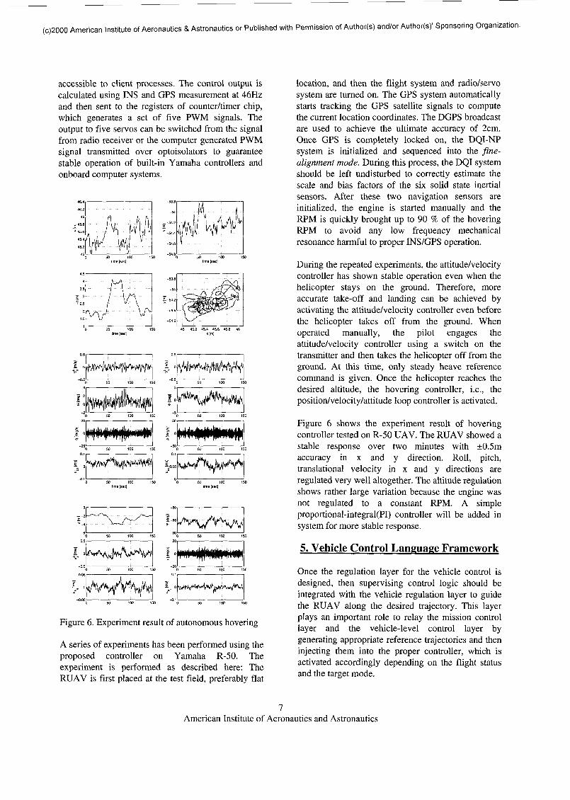
Vehicle Control Language, or VCL, is an applicationand development tool for UAV systems, operating ina hierarchical structure as shown in Figure 7. Thisapproach allows to program complex behavior of theUAV adaptively without rewriting program as themission changes. The sequence of motion commandsis described in a script language form understandableto human. VCL module consists of user interface parton ground station, language interpreter and sequenceron the UAV side.
Figure 7. Hierarchical structure of VCL processing
Figure 8. Waypoint generation using graphical userinterface
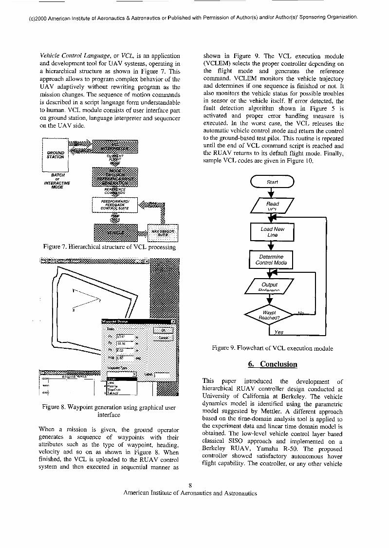
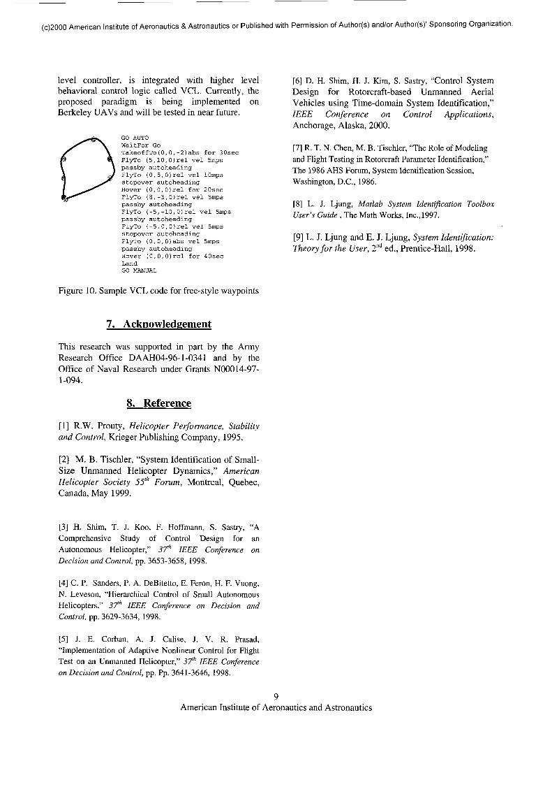
When a mission is given, the ground operatorgenerates a sequence of waypoints with theirattributes such as the type of waypoint, heading,velocity and so on as shown in Figure 8. Whenfinished, the VCL is uploaded to the RUAV controlsystem and then executed in sequential manner as
shown in Figure 9. The VCL execution module(VCLEM) selects the proper controller depending onthe flight mode and generates the referencecommand. VCLEM monitors the vehicle trajectoryand determines if one sequence is finished or not. Italso monitors the vehicle status for possible troublesin sensor or the vehicle itself. If error detected, thefault detection algorithm shown in Figure 5 isactivated and proper error handling measure isexecuted. In the worst case, the VCL releases theautomatic vehicle control mode and return the controlto the ground-based test pilot. This routine is repeateduntil the end of VCL command script is reached andthe RUAV returns to its default flight mode. Finally,sample VCL codes are given in Figure 10.
/Output /
______Oofarer.^ /
Figure 9. Flowchart of VCL execution module
6. Conclusion
This paper introduced the development ofhierarchical RUAV controller design conducted atUniversity of California at Berkeley. The vehicledynamics model is identified using the parametricmodel suggested by Mettler. A different approachbased on the time-domain analysis tool is applied tothe experiment data and linear time domain model isobtained. The low-level vehicle control layer basedclassical SISO approach and implemented on aBerkeley RUAV, Yamaha R-50. The proposedcontroller showed satisfactory autonomous hoverflight capability. The controller, or any other vehicle
American Institute of Aeronautics and Astronautics
(c)2000 American Institute of Aeronautics & Astronautics or Published with Permission of Author(s) and/or Author(s)1 Sponsoring Organization.
level controller, is integrated with higher levelbehavioral control logic called VCL. Currently, theproposed paradigm is being implemented onBerkeley UAVs and will be tested in near future.
GO AUTOWaitFor GoTakeoffTo(0,0,-2)abs for 30secFlyTo (5,10, Orel vel Smpspassby autoheadingFlyTo (0,5,0)rel vel lOmpsstopover autoheadingHover (0,0,0)rel for 20secFlyTo (8,-5, Orel vel Smpspassby autoheadingFlyTo (-5,-10,OJrel vel Smpspassby autoheadingFlyTo (-5,0,0)rel vel Smpsstopover autoheadingFlyTo (0,0,0labs vel Smpspassby autoheadingHover (0,0,0)rel for 40secLandGO MANUAL
Figure 10. Sample VCL code for free-style waypoints
7. Acknowledgement
This research was supported in part by the ArmyResearch Office DAAH04-96-1-0341 and by theOffice of Naval Research under Grants N00014-97-1-094.
8. Reference
[1] R.W. Prouty, Helicopter Performance, Stabilityand Control, Krieger Publishing Company, 1995.
[2] M. B. Tischler, "System Identification of Small-Size Unmanned Helicopter Dynamics," AmericanHelicopter Society 55th Forum, Montreal, Quebec,Canada, May 1999.
[3] H. Shim, T. J. Koo, F. Hoffmann, S. Sastry, "AComprehensive Study of Control Design for anAutonomous Helicopter," 37th IEEE Conference onDecision and Control, pp. 3653-3658, 1998.
[4] C. P. Sanders, P. A. DeBitetto, E. Feron, H. F. Vuong,N. Leveson, "Hierarchical Control of Small AutonomousHelicopters," 37th IEEE Conference on Decision andControl, pp. 3629-3634, 1998.
[5] J. E. Corban, A. J. Calise, J. V. R. Prasad,"Implementation of Adaptive Nonlinear Control for FlightTest on an Unmanned Helicopter," 37th IEEE Conferenceon Decision and Control, pp. Pp. 3641-3646, 1998.
[6] D. H. Shim, H. J. Kirn, S. Sastry, "Control SystemDesign for Rotorcraft-based Unmanned AerialVehicles using Time-domain System Identification,"IEEE Conference on Control Applications,Anchorage, Alaska, 2000.
[7] R. T. N. Chen, M. B. Tischler, "The Role of Modelingand Flight Testing in Rotorcraft Parameter Identification,"The 1986 AHS Forum, System Identification Session,Washington, D.C., 1986.
[8] L. J. Ljung, Matlab System Identification ToolboxUser's Guide , The Math Works, Inc.,1997.
[9] L. J. Ljung and E. J. Ljung, System Identification:Theory for the User, 2nd ed., Prentice-Hall, 1998.
American Institute of Aeronautics and Astronautics