Embed Size (px)
Citation preview
HGU-56/P MAXILLOFACIAL SHIELD
ASSEMBLY
Installation/Operation Instructions
© 2015 Gentex Corporation
ITAR RESTRICTED
This document contains technical data subject to U.S. government export control. Such technical data may not be transferred, transshipped on a noncontinuous voyage or otherwise disposed of in any other country, either in its original form or after being incorporated into other end-items, without the prior written approval of the U.S. Department of State. 22 CFR Section 123.9(B) Information contained herein is Gentex proprietary.

When you replace components or install additional components on Gentex products, always use genuine factory-new Gentex parts. This will ensure a correct fit and maintain the safety of the product. Use of non-Gentex parts (salvage, refurbished, etc.) for replacement or additional installation will void any product warranty and may compromise the safety of the user.
Contents
DESCRIPTION................................................. 1
INSTALLATION ............................................... 2Tools, Equipment, and Materials Required ...............................2
Installing Strikers ......................................................................2
Trimming MFS for ANVIS Compatibility (If Necessary) ............8
OPERATION .................................................... 9Attaching MFS ............................................................................9
Removing MFS............................................................................9
Using Anti-Fogging Solution ....................................................10
MAINTENANCE ............................................. 10Repairing Edge Beading ..........................................................10
Replacing Striker .....................................................................11
Replacing Latch .......................................................................11
Cleaning MFS ...........................................................................11
PARTS LIST .................................................. 12

1
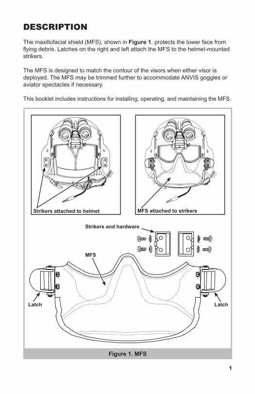
DESCRIPTIONThe maxillofacial shield (MFS), shown in Figure 1, protects the lower face from flying debris. Latches on the right and left attach the MFS to the helmet-mounted strikers.
The MFS is designed to match the contour of the visors when either visor is deployed. The MFS may be trimmed further to accommodate ANVIS goggles or aviator spectacles if necessary.
This booklet includes instructions for installing, operating, and maintaining the MFS.
Strikers attached to helmet
MFS
Strikers and hardware
Latch
MFS attached to strikers
Latch
Figure 1. MFS
2
INSTALLATION
Tools, Equipment, and Materials Required• Compass
• Screwdriver, cross-tip
• Rotary tool kit
• Drum, sanding
• Band, abrasive
• Drill, electrical, portable
• Drill, twist, 1/16
• Drill, twist, 9/64
• Drill, twist, 3/16
• Respirator
• Maxillofacial Shield
• Striker Hardware Kit
• Latch Hardware Kit
• White glue
• Pencil
• Goggles, eye-protective
• 2x4 wood block
Installing Strikers
1. Remove the dual visor assembly from the helmet.
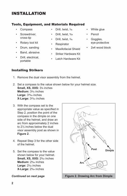
2. Set a compass to the value shown below for your helmet size. Small, XS, XXS: 31/8 inches Medium: 33/16 inches Large: 319/64 inches X-Large: 321/64 inches
3. With the compass set to the appropriate value as specified in Step 2, position the point of the compass in the dimple on one side of the helmet, and draw an arc from approximately 2 inches to 2½ inches below the dual visor assembly post as shown in Figure 2.
4. Repeat Step 3 for the other side of the helmet.
5. Set the compass to the value shown below for your helmet. Small, XS, XXS: 29/64 inches Medium: 29/64 inches Large: 25/32 inches X-Large: 29/64 inches
Continued on next page Figure 2. Drawing Arc from Dimple
Arc
Post Dimple
3
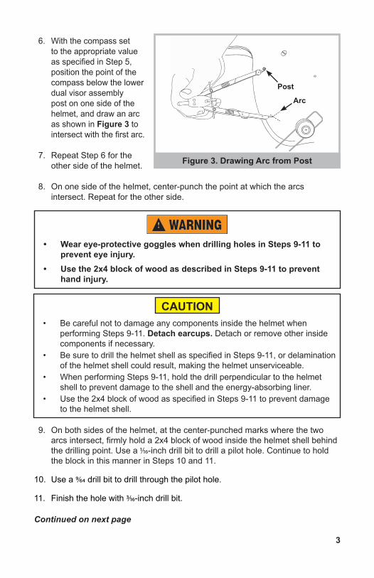
6. With the compass set to the appropriate value as specified in Step 5, position the point of the compass below the lower dual visor assembly post on one side of the helmet, and draw an arc as shown in Figure 3 to intersect with the first arc.
7. Repeat Step 6 for the other side of the helmet.
8. On one side of the helmet, center-punch the point at which the arcs intersect. Repeat for the other side.
9. On both sides of the helmet, at the center-punched marks where the two arcs intersect, firmly hold a 2x4 block of wood inside the helmet shell behind the drilling point. Use a 1/16-inch drill bit to drill a pilot hole. Continue to hold the block in this manner in Steps 10 and 11.
10. Use a 9/64 drill bit to drill through the pilot hole.
11. Finish the hole with 3/16-inch drill bit.
Continued on next page
Figure 3. Drawing Arc from Post
• Wear eye-protective goggles when drilling holes in Steps 9-11 to prevent eye injury.
• Use the 2x4 block of wood as described in Steps 9-11 to prevent hand injury.
• Be careful not to damage any components inside the helmet when performing Steps 9-11. Detach earcups. Detach or remove other inside components if necessary.
• Be sure to drill the helmet shell as specified in Steps 9-11, or delamination of the helmet shell could result, making the helmet unserviceable.
• When performing Steps 9-11, hold the drill perpendicular to the helmet shell to prevent damage to the shell and the energy-absorbing liner.
• Use the 2x4 block of wood as specified in Steps 9-11 to prevent damage to the helmet shell.
CAUTION
Arc
Post
4
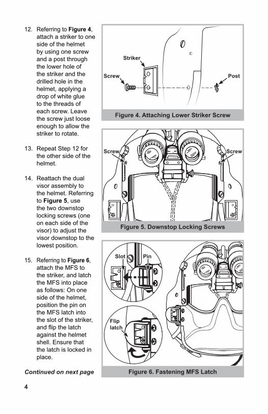
12. Referring to Figure 4, attach a striker to one side of the helmet by using one screw and a post through the lower hole of the striker and the drilled hole in the helmet, applying a drop of white glue to the threads of each screw. Leave the screw just loose enough to allow the striker to rotate.
13. Repeat Step 12 for the other side of the helmet.
14. Reattach the dual visor assembly to the helmet. Referring to Figure 5, use the two downstop locking screws (one on each side of the visor) to adjust the visor downstop to the lowest position.
15. Referring to Figure 6, attach the MFS to the striker, and latch the MFS into place as follows: On one side of the helmet, position the pin on the MFS latch into the slot of the striker, and flip the latch against the helmet shell. Ensure that the latch is locked in place.
Continued on next page
Figure 4. Attaching Lower Striker Screw
Figure 5. Downstop Locking Screws
Figure 6. Fastening MFS Latch
PostScrew
Striker
Screw
Slot
Flip latch
Pin
Screw
5
NOTE:• The helmet can be donned or doffed while the MFS is attached to either
side and swung open. However, if the ML-24 light (from Seitz Scientific Industries, Inc.) is attached to the MFS, the MFS should be swung open from the right side as worn to avoid disconnecting the light.
• The MFS can also be swung open while the helmet is worn, allowing the crewmember to eat or drink.
• If the helmet is stowed with the MFS attached, the shield should be secured to the helmet on both sides.
16. Swing the MFS closed, and fasten the other latch as described in Step 15.
17. Adjust the MFS position as follows:
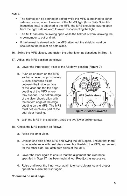
a. Lower the inner (clear) visor to the full down position (Figure 7).
b. Push up or down on the MFS so that an even, approximately 1/16-inch clearance exists between the inside surface of the visor and the top edge beading of the MFS where they overlap. The bottom edge of the visor should align with the bottom edge of the edge beading on the MFS. The MFS must not touch any part of the dual visor housing.
c. With the MFS in this position, snug the two lower striker screws.
18. Check the MFS position as follows:
a. Raise the inner visor.
b. Unlatch one side of the MFS and swing the MFS open. Ensure that there is no interference with dual visor assembly. Re-latch the MFS, and repeat for the other side. Re-latch both sides of the MFS.
c. Lower the visor again to ensure that the alignment and clearance specified in Step 17 has been maintained. Readjust as necessary.
d. Raise and lower the inner visor again to ensure clearance and proper operation. Raise the visor again.
Continued on next page
Figure 7. Visor Lowered
MFS (inside visor)
6
19. Drill the pilot holes as follows:
a. With both sides of the MFS latched in place and the two lower striker fasteners snug, firmly hold a 2x4 block of wood inside the helmet shell behind the drilling point.
b. Use a drill with a 1/16-inch drill bit to drill a pilot hole through the upper hole of both strikers.
c. Continue to hold the wood block behind the drilling point, and drill the upper hole of both strikers with a 9/64-inch drill bit.
20. Drill the final holes as follows:
a. Remove the MFS, loosen the two lower striker fasteners, and rotate both strikers out of the way to allow access to the pilot holes drilled in Step 19.
b. Firmly hold a 2x4 block of wood inside the helmet shell behind the drilling point.
c. Using a drill with a 3/16-inch drill bit, drill through both pilot holes.
Continued on next page
• Wear eye-protective goggles when drilling holes in Steps 19 and 20 to prevent eye injury.
• Use the 2x4 block of wood as described in Steps 19 and 20 to prevent hand injury.
• Be careful not to damage any components inside the helmet when performing Steps 19 and 20. Detach earcups. Detach or remove other inside components if necessary.
• Be sure to drill the helmet shell as specified in Steps 9-11, or delamination of the helmet shell could result, making the helmet unserviceable.
• When performing Steps 19 and 20, hold the drill perpendicular to the helmet shell to prevent damage to the shell and the energy-absorbing liner.
• Use the 2x4 block of wood as specified in Steps 19 and 20 to prevent damage to the helmet shell.
• When performing Step 20, ensure that both strikers are rotated out of the way before you begin drilling. Do not drill through the strikers with the 3/16-inch drill bit.
CAUTION
7
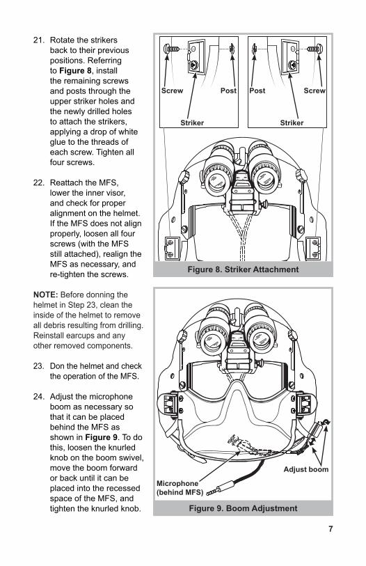
21. Rotate the strikers back to their previous positions. Referring to Figure 8, install the remaining screws and posts through the upper striker holes and the newly drilled holes to attach the strikers, applying a drop of white glue to the threads of each screw. Tighten all four screws.
22. Reattach the MFS, lower the inner visor, and check for proper alignment on the helmet. If the MFS does not align properly, loosen all four screws (with the MFS still attached), realign the MFS as necessary, and re-tighten the screws.
NOTE: Before donning the helmet in Step 23, clean the inside of the helmet to remove all debris resulting from drilling. Reinstall earcups and any other removed components.
23. Don the helmet and check the operation of the MFS.
24. Adjust the microphone boom as necessary so that it can be placed behind the MFS as shown in Figure 9. To do this, loosen the knurled knob on the boom swivel, move the boom forward or back until it can be placed into the recessed space of the MFS, and tighten the knurled knob.
Figure 8. Striker Attachment
Figure 9. Boom Adjustment
PostPostScrew Screw
Striker Striker
Adjust boom
Microphone (behind MFS)
8
Trimming MFS for ANVIS Compatibility (If Necessary)
1. Have the crewmember don the helmet and attach the MFS.
2. Attach the night vision goggles to the ANVIS mount.
3. Remove the lens caps and lower the night vision goggles. If the goggles clear the MFS and are properly positioned over the eyes, no trimming is needed. If the goggles contact the shield, trim the shield as follows:
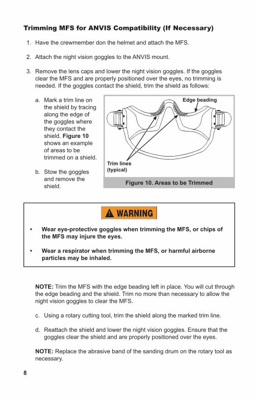
a. Mark a trim line on the shield by tracing along the edge of the goggles where they contact the shield. Figure 10 shows an example of areas to be trimmed on a shield.
b. Stow the goggles and remove the shield.
NOTE: Trim the MFS with the edge beading left in place. You will cut through the edge beading and the shield. Trim no more than necessary to allow the night vision goggles to clear the MFS.
c. Using a rotary cutting tool, trim the shield along the marked trim line.
d. Reattach the shield and lower the night vision goggles. Ensure that the goggles clear the shield and are properly positioned over the eyes.
NOTE: Replace the abrasive band of the sanding drum on the rotary tool as necessary.
Figure 10. Areas to be Trimmed
• Wear eye-protective goggles when trimming the MFS, or chips of the MFS may injure the eyes.
• Wear a respirator when trimming the MFS, or harmful airborne particles may be inhaled.
Trim lines (typical)
Edge beading
9
OPERATIONNOTE: The helmet can be donned or doffed while the MFS is attached to either side and swung open. However, if the ML-24 light (from Seitz Scientific Industries, Inc.) is attached, the MFS should be swung open from the right side as worn to avoid disconnecting the light. The MFS can also be swung open while the helmet is worn, allowing the crewmember to eat or drink. If the helmet is stowed with the MFS attached, the shield should be secured to the helmet on both sides.
Attaching MFS
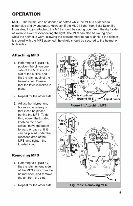
1. Referring to Figure 11, position the pin on one side of the MFS into the slot of the striker, and flip the latch against the helmet shell. Ensure that the latch is locked in place.
2. Repeat for the other side.
3. Adjust the microphone boom as necessary so that it can be placed behind the MFS. To do this, loosen the knurled knob on the boom swivel, move the boom forward or back until it can be placed under the recessed area of the MFS, and tighten the knurled knob.
Removing MFS
1. Referring to Figure 12, flip the latch on one side of the MFS away from the helmet shell, and remove the pin from the slot.
2. Repeat for the other side.
Figure 11. Attaching MFS
Figure 12. Removing MFS
Slot
Slot
Flip latch
Flip latch
Pin
Pin
Adjust boomMicrophone (behind MFS)
10
Using Anti-Fogging Solution
To help prevent the visor lenses from fogging when the MFS is worn, use Sea Drops™ anti-fogging solution as follows:
1. Apply two drops of anti-fogging solution to the inside surface of each lens.
2. Rub the solution over the entire surface of the lens.
3. Wait 10 seconds, then buff with a Micronet™ microfiber cloth or any soft, dry cloth until the lens is clear.
(Sea Drops™ and Micronet™ are manufactured by McNett Corporation, 1411 Meador Ave., Bellingham, WA 98229, phone 360-671-2227.)
MAINTENANCE
Repairing Edge Beading
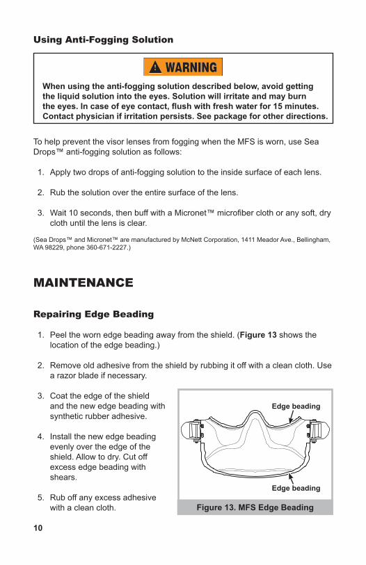
1. Peel the worn edge beading away from the shield. (Figure 13 shows the location of the edge beading.)
2. Remove old adhesive from the shield by rubbing it off with a clean cloth. Use a razor blade if necessary.
3. Coat the edge of the shield and the new edge beading with synthetic rubber adhesive.
4. Install the new edge beading evenly over the edge of the shield. Allow to dry. Cut off excess edge beading with shears.
5. Rub off any excess adhesive with a clean cloth.
When using the anti-fogging solution described below, avoid getting the liquid solution into the eyes. Solution will irritate and may burn the eyes. In case of eye contact, flush with fresh water for 15 minutes. Contact physician if irritation persists. See package for other directions.
Figure 13. MFS Edge Beading
Edge beading
Edge beading
11
Replacing Striker
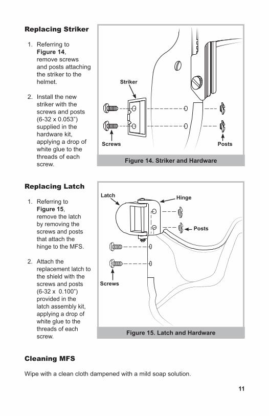
1. Referring to Figure 14, remove screws and posts attaching the striker to the helmet.
2. Install the new striker with the screws and posts (6-32 x 0.053”) supplied in the hardware kit, applying a drop of white glue to the threads of each screw.
Replacing Latch
1. Referring to Figure 15, remove the latch by removing the screws and posts that attach the hinge to the MFS.
2. Attach the replacement latch to the shield with the screws and posts (6-32 x 0.100”) provided in the latch assembly kit, applying a drop of white glue to the threads of each screw.
Cleaning MFS
Wipe with a clean cloth dampened with a mild soap solution.
Figure 14. Striker and Hardware
Figure 15. Latch and Hardware
Posts
Posts
Screws
Screws
Striker
Latch Hinge
12
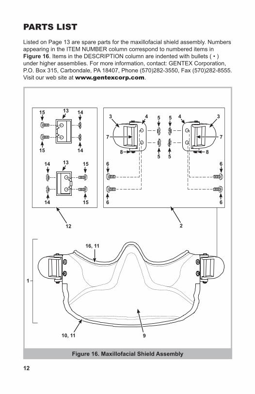
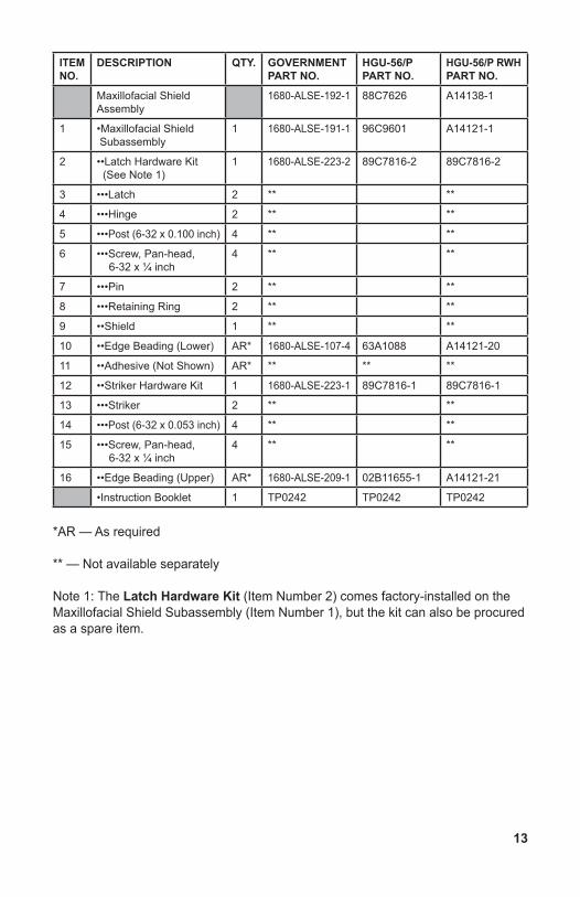
PARTS LISTListed on Page 13 are spare parts for the maxillofacial shield assembly. Numbers appearing in the ITEM NUMBER column correspond to numbered items in Figure 16. Items in the DESCRIPTION column are indented with bullets ( • ) under higher assemblies. For more information, contact: GENTEX Corporation, P.O. Box 315, Carbondale, PA 18407, Phone (570)282-3550, Fax (570)282-8555. Visit our web site at www.gentexcorp.com.
10, 11
Figure 16. Maxillofacial Shield Assembly
1
212
16, 11
13
13
14
14
15
15
15
15
14
14
9
3 34 45
5
6
6
7
8 8
7
6
6
5
5
13
ITEM NO.
DESCRIPTION QTY. GOVERNMENT PART NO.
HGU-56/P PART NO.
HGU-56/P RWH PART NO.
Maxillofacial Shield Assembly
1680-ALSE-192-1 88C7626 A14138-1
1 •Maxillofacial Shield Subassembly
1 1680-ALSE-191-1 96C9601 A14121-1
2 ••Latch Hardware Kit (See Note 1)
1 1680-ALSE-223-2 89C7816-2 89C7816-2
3 •••Latch 2 ** **
4 •••Hinge 2 ** **
5 •••Post (6-32 x 0.100 inch) 4 ** **
6 •••Screw, Pan-head, 6-32 x ¼ inch
4 ** **
7 •••Pin 2 ** **
8 •••Retaining Ring 2 ** **
9 ••Shield 1 ** **
10 ••Edge Beading (Lower) AR* 1680-ALSE-107-4 63A1088 A14121-20
11 ••Adhesive (Not Shown) AR* ** ** **
12 ••Striker Hardware Kit 1 1680-ALSE-223-1 89C7816-1 89C7816-1
13 •••Striker 2 ** **
14 •••Post (6-32 x 0.053 inch) 4 ** **
15 •••Screw, Pan-head, 6-32 x ¼ inch
4 ** **
16 ••Edge Beading (Upper) AR* 1680-ALSE-209-1 02B11655-1 A14121-21
•Instruction Booklet 1 TP0242 TP0242 TP0242
*AR — As required
** — Not available separately
Note 1: The Latch Hardware Kit (Item Number 2) comes factory-installed on the Maxillofacial Shield Subassembly (Item Number 1), but the kit can also be procured as a spare item.