Embed Size (px)
Citation preview

HEPA Media Options
2
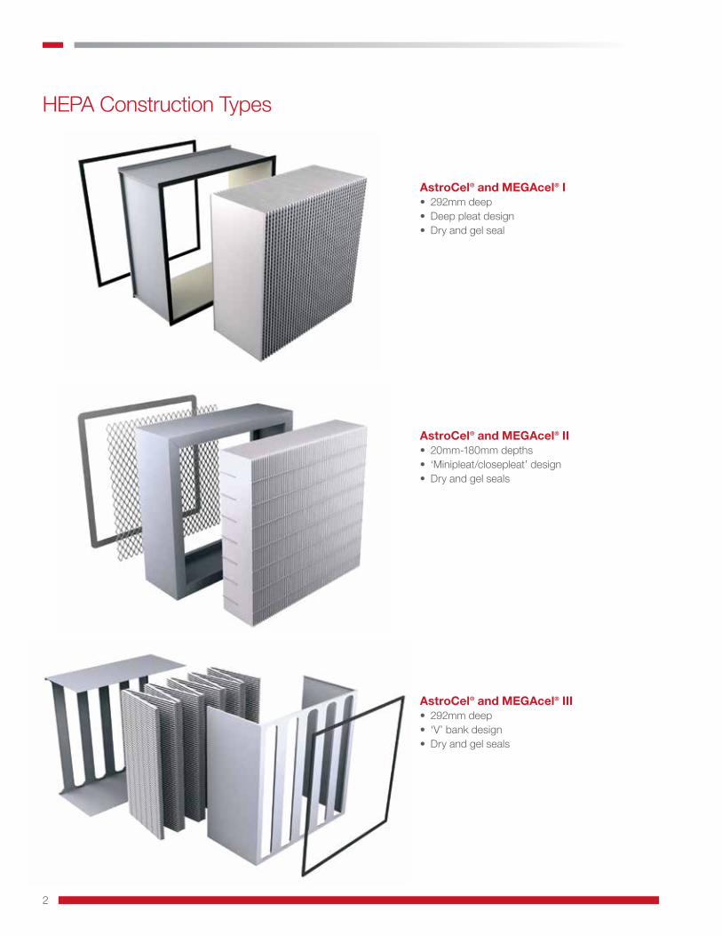
HEPA Construction Types
AstroCel® and MEGAcel® I• 292mm deep• Deep pleat design• Dry and gel seal
AstroCel® and MEGAcel® II• 20mm-180mm depths• ‘Minipleat/closepleat’ design• Dry and gel seals
AstroCel® and MEGAcel® III• 292mm deep• ‘V’ bank design• Dry and gel seals

3
Media – The Heart of the Filter and the CleanroomUnderstanding the Media Options Available to YouHEPA and ULPA filters made with microglass media have stood the test of time for over 75 years. However, aside from the development of “low boron” microglass media for the microelectronics industry, the technology has seen very little innovation since its inception. While its filtration performance has been proven throughout its long history, unfortunately so has its fragility. Despite its well documented filtration performance, the delicate nature of glass fiber media continues to present a potential risk for damage that should be considered when selecting the ideal media for a given application.Conversely, membrane media technologies have seen and experienced continuous innovation and adoption across many industries and applications over the past 30 years. In the early 1990’s, increased demand from the booming microelectronics industry for HEPA and ULPA grade air filters with reduced offgassing properties and improved energy efficiency created an opportunity for innovation in HEPA and ULPA grade medias. Within that same time period, Daikin Industries discovered an ultrafine fiber structure that would enable a revolutionary change in air filter membrane media development.
Proven Alternatives to Glass Fiber MediaThe development of Daikin’s unique ultrafine fiber ePTFE membrane media offered an alternative option to glass fiber filters for the microelectronics industry that provided the lowest offgassing properties, lowest energy consumption, and far superior tensile strength and durability. This technological advancement enabled the industry to dramatically reduce operating costs, while also improving production yield. Since that time, ePTFE media has become the media of choice for the microelectronics industry.
Expanded Portfolio of Membrane TechnologiesMembrane technologies have evolved since the discovery of the ultrafine fibers by Daikin Industries in 1988. The main benefits remain the same: excellent pressure drop, ultra-low emissions, and superior durability when compared to glass fiber media. However, the portfolio of available media types for specific applications has expanded.
Evolution Meets Revolution: Introducing the Flouroresin MembraneExpanded Fluororesin Membrane, or eFRM, is the next generation of membrane media technology, designed specifically for applications where high concentrations of oil-based test aerosols (i.e. PAO) and fine particulate (i.e. Hydrocarbons) are present. This unique recipe of ultra-fine membrane layers and support structures now enables these demanding environments to take advantage of the same membrane media performance that other applications have enjoyed for decades.
Microglass Media:Wetlaid media made from borosilicate glass fibers and adhesive binders.• Available in E10 –U17• Compatible with Discrete Particle
Counters (DPC) testing and photometric test methods
ePTFE Membrane Media:Single layer of expanded PTFE supported by a layer of spun bonded synthetic media on the upstream and downstream side.• Available in H13 –U17• Standard for Microelectronic and Tool
Market• Compatible with Discrete Particle
Counters (DPC) testing
eFRM Membrane Media:Dual layers of expanded Fluororesin membrane supported by a layer of spun bonded synthetic media on the upstream and downstream side. • Available in H13 –H14• Designed for ultra-high particulate
loading, including oil-based test aerosols• Compatible with photometric test
methods
(10,000x)
(10,000x)
(10,000x)
1st eFRM Layer(Low Fibril Density)
(10,000x)
2nd eFRM Layer(High Fibril Density)
Media Resilience Comparison
AAF Flanders’ HEPA/ULPA filters utilizing Daikin’s ultra-fine fiber membrane media technology are the product of choice in the most demanding environments.
Wet laid glass fiber media is delicate and vulnerable to various levels of degradation, ranging from pinhole leaks to irreparable damage.

4
Selecting the Right HEPA/ULPA FilterHEPA/ULPA Filter Failure Models
HANDLING TESTING &CERTIFICATION
CLEANING UNINTENDEDCONTACTManufacturing Process
Transport/DeliveryInstalling
Removing/Installing
Scanning of Filters
Moving Equipment
Repair/Maintenance
Cleaning the Screen
High Pressure Water
Key Risk Based Considerations: Modes of HEPA/ULPA Filter FailureNow that we understand the critical role of media selection in the choice of HEPA/ULPA filters for a given application, it’s important to also review some of the in-situ risk that the filter will be confronted with in the clean space.
HEPA Filters typically fail due to some form of contact combined with the poor mechanical strength of the media.
Summary of Considerations for HEPA/ULPA Filter SelectionThis product guide contains multiple product options and configurations for your review and selection. Below is a helpful checklist of items to consider as you make your final selection.
Media Integrity• Highest level of mechanical strength for resistance to damage, leaking, or failure• Chemically inert, which reduces media degradation in highly corrosive environments• Hydrophobic (water resistant)
Economy and Testing• Lowest available pressure drop to reduce energy consumption and changeout cycles• Lowest off-gassing of chemical components to minimize risk of contamination• Ability to perform local field testing per standards for your environment
Total Cost of Ownership• Clearly quantify all potential operational risks associated with your filter selection• Invest in technology that improves operational performance and reduces the effort required for maintenance and repair• Partner with a supplier that can provide professional guidance and a fully integrated system solution
Comparing Glass Fiber and Membrane Media OptionsThe risks listed above can be mitigated by the use of durable ePTFE or eFRM membrane-based HEPA/ULPA filters. The table below shows a comparison of physical properties of ePTFE, eFRM, and glass fiber HEPA filters for consideration when durability and reliability are key concerns.
Results based on Test Standard DIN EN 29073-3.
EnergySavings
Initia
l Res
istan
ce
Filter Face Velocity
Ultrafine MembraneMediaMicroglass Media
What to Look for in HEPA/ULPA Filters
Tensile Strength
Ultrafine Membrane MediaMicroglass Media
Flat Folded Flat Folded
41.6
312.8
3.8
318.0350.0
300.0
250.0
200.0
150.0
100.0
50.0
0.0
Tens
ile S
treng
th (N
)
Flat: 8x Higher
Folded: 84x Higher
Results based on Test Standard DIN EN 12947-2.
Abrasion Resistance – Flat
Ultrafine Membrane MediaMicroglass Media
20
20,00020
16
12
8
4
0
Abra
sion
Res
ista
nce
(# ru
bbin
g cy
cles
)
1000x Higher
Results based on Test Standard DIN EN 13938-2.
Burst Pressure – Flat
Ultrafine Membrane MediaMicroglass Media
0.0
6.47.0
6.0
5.0
4.0
3.0
2.0
1.0
0.0
Burs
t Pre
ssur
e (k
g/cm
2)
Endlessly Higher

5
Filter Efficiency
EPA Efficiency Particulate Air Filter
HEPA High Efficiency Particulate Air Filter
ULPA Ultra Low Penetration Air Filter
Traditional designation for a HEPA: 99.97 @ 0.3μm
Traditional designation for an ULPA: 99.999 @ 0.12μm
Today we classify at MPPS E10-U17: XX.X5 @ MPPS
(Most Penetrating Particle Size)
See EN-1822 Filter Classification in prior pages.
100.0000
99.9998
99.9996
99.9994
99.9992
99.9990
0.0002
0.0004
0.0006
0.0008
0.0010
Penetration Rate (%)
Particle size (µm)0.01 0..1 1
MPPS ePTFEMembrane: 0.07 µm
MPPS TraditionalGlass Media: 0.13 µm
Filtration efficiency @MPPS determined according to:EN1822-5-2009 - Annex A, alternative procedure for testing membrane media with MPPS < 0.1µm
Laskin Nozzle ‘Cold’ PAO Pressure Drop Data
Pressure Drop (Static) vs Time
Time (min)
200
175
150
125
100
75
50
25
00 10 20 30 40 50 60 70
∆P (P
a)
0.80
0.70
0.60
0.50
0.40
0.30
0.20
0.10
0
∆P (in w.g.)
AstroCel® 4" 120 FPM (0.6 m/s) MEGAcel® 4" 120 FPM (0.6 m/s)
MEGAcel® 4" 200 FPM (1.0 m/s)AstroCel® 2" 120 FPM (0.6 m/s) MEGAcel® 2" 120 FPM (0.6 m/s)AstroCel® 4" 200 FPM (1.0 m/s)
PAO Concentration: 15µg/l
• Stable pressure development for 1 hour with local injection
Average PAO Concentration: 15µg/l
MPPS Filter Designations Microglass and Membrane Media
6
HEPA/ULPA Filters – Series I
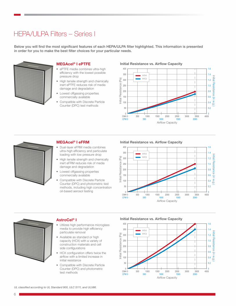
AstroCel® I• Utilizes high performance microglass
media to provide high efficiency particulate removal
• Available as standard or high capacity (HCX) with a variety of construction materials and cell side configurations
• HCX configuration offers twice the airflow with a limited increase in initial resistance
• Compatible with Discrete Particle Counter (DPC) and photometric test methods
Below you will find the most significant features of each HEPA/ULPA filter highlighted. This information is presented in order for you to make the best filter choices for your particular needs.
MEGAcel® I ePTFE• ePTFE media combines ultra-high
efficiency with the lowest possible pressure drop
• High tensile strength and chemically inert ePTFE reduces risk of media damage and degradation
• Lowest offgassing properties commercially available
• Compatible with Discrete Particle Counter (DPC) test methods
MEGAcel® I eFRM• Dual-layer eFRM media combines
ultra-high efficiency and particulate loading with low pressure drop
• High tensile strength and chemically inert eFRM reduces risk of media damage and degradation
• Lowest offgassing properties commercially available
• Compatible with Discrete Particle Counter (DPC) and photometric test methods, including high concentration oil-based aerosol testing
UL classified according to UL Standard 900, ULC S111, and UL586.
Initial Resistance vs. Airflow Capacity
Initial Resistance vs. Airflow Capacity
500CMH 0 1000 1500 2000 2500 3000 3500 4000500CFM 0 1000 1500 2000
Airflow Capacity
0
50
100
150
200
250
300
350
400
Initia
l Res
istan
ce (P
a)
0
0.2
0.4
0.6
0.8
1.0
1.2
1.4
1.6
Initial Resistance (in w.g.)
H14H13
500CMH 0 1000 1500 2000 2500 3000 3500 4000500CFM 0 1000 1500 2000
Airflow Capacity
0
50
100
150
200
250
300
350
400
Initia
l Res
istan
ce (P
a)
0
0.2
0.4
0.6
0.8
1.0
1.2
1.4
1.6
Initial Resistance (in w.g.)
H14H13
Initial Resistance vs. Airflow Capacity
500CMH 0 1000 1500 2000 2500 3000 3500 4000500CFM 0 1000 1500 2000
Airflow Capacity
0
50
100
150
200
250
300
350
400
Initia
l Res
istan
ce (P
a)
0
0.2
0.4
0.6
0.8
1.0
1.2
1.4
1.6
Initial Resistance (in w.g.)
H14H13

7
HEPA/ULPA Filters – Series II
AstroCel® II• Utilizes high performance microglass media to provide high
efficiency particulate removal• Optimally spaced mini-pleat media pack further minimizes pressure
drop in this cleanroom panel configuration• Wide range of efficiencies and pack depth options available• Compatible with Discrete Particle Counter (DPC) and photometric
test methods
MEGAcel® II ePTFE• ePTFE media combines ultra-high efficiency with the lowest
possible pressure drop• High tensile strength and chemically inert ePTFE reduces risk
of media damage and degradation • Lowest offgassing properties commercially available• Compatible with Discrete Particle Counter (DPC) test methods
MEGAcel® II eFRM• Dual-layer eFRM media combines ultra-high efficiency and
particulate loading with low pressure drop• High tensile strength and chemically inert eFRM reduces risk
of media damage and degradation• Lowest offgassing properties commercially available • Compatible with Discrete Particle Counter (DPC) and photometric
test methods, including high concentration oil-based aerosol testing

8
HEPA/ULPA Filters – Series II
MEGAcel® II eFRM H13/H14 Initial Resistance vs. Filter Face Velocity
AstroCel® II U15/U16 Initial Resistance vs. Filter Face Velocity
MEGAcel II ePTFE H13/H14 Initial Resistance vs. Filter Face Velocity
MEGAcel II ePTFE U15/U16 Initial Resistance vs. Filter Face Velocity
AstroCel® II H13/H14 Initial Resistance vs. Filter Face Velocity
(m/s) 0.2 0.25 0.3 0.35 0.4 0.45 0.550FPM 40 60 70 80 90 100
Filter Face Velocity
0
20
120
160
180
200
140
100
40
60
80
Initia
l Res
istan
ce (P
a)
0
0.08
0.16
0.24
0.32
0.40
0.48
0.56
0.80
0.72
0.64
Initial Resistance (in w.g.)
H13 30 mmH13 50 mmH14 30 mmH14 50 mm
(m/s) 0.2 0.25 0.3 0.35 0.4 0.45 0.550FPM 40 60 70 80 90 100
Filter Face Velocity
0
20
120
160
180
200
140
100
40
60
80
Initia
l Res
istan
ce (P
a)
0
0.08
0.16
0.24
0.32
0.40
0.48
0.56
0.80
0.72
0.64
Initial Resistance (in w.g.)
H13 30 mmH13 50 mmH14 30 mmH14 50 mm
(m/s) 0.2 0.25 0.3 0.35 0.4 0.45 0.550FPM 40 60 70 80 90 100
Filter Face Velocity
0
20
120
160
180
200
140
100
40
60
80
Initia
l Res
istan
ce (P
a)
0
0.08
0.16
0.24
0.32
0.40
0.48
0.56
0.80
0.72
0.64
Initial Resistance (in w.g.)
H13 48 mmH13 96 mmH14 48 mmH14 96 mm
(m/s) 0.2 0.25 0.3 0.35 0.4 0.45 0.550FPM 40 60 70 80 90 100
Filter Face Velocity
0
20
120
160
180
200
140
100
40
60
80
Initia
l Res
istan
ce (P
a)
0
0.08
0.16
0.24
0.32
0.40
0.48
0.56
0.80
0.72
0.64
Initial Resistance (in w.g.)
U15 48 mmU15 96 mmU16 48 mmU16 96 mm
(m/s) 0.2 0.25 0.3 0.35 0.4 0.45 0.550FPM 40 60 70 80 90 100
Filter Face Velocity
0
20
120
160
180
200
140
100
40
60
80
Initia
l Res
istan
ce (P
a)
0
0.08
0.16
0.24
0.32
0.40
0.48
0.56
0.80
0.72
0.64
Initial Resistance (in w.g.)
U15 30 mmU15 50 mmU16 30 mmU16 50 mm
AAF Flanders’ ultra-high efficiency membrane medias are trusted by more cleanroom manufacturers than any other membrane medias in the world

9
HEPA/ULPA Filters – Series IIIMEGAcel® III ePTFE• V-shaped filter configuration, combined
with ePTFE media, delivers higher flow at the lowest possible pressure drop vs traditional box style HEPA filters
• High tensile strength and chemically inert ePTFE reduces risk of media damage and degradation
• Lowest offgassing properties commercially available
• Compatible with Discrete Particle Counter (DPC) test methods as access and instrumentation allow
MEGAcel® III eFRM• V-shaped filter configuration, combined
with dual-layer eFRM media, delivers higher flow and high capacity particulate loading with low pressure drop
• High tensile strength and chemically inert eFRM reduces risk of media damage and degradation
• Lowest offgassing properties commercially available
• Compatible with Discrete Particle Counter (DPC) and photometric test methods, including high concentration oil-based aerosol testing as access and instrumentation allow
AstroCel® III• V-shaped filter configuration, combined
with high performance microglass media, delivers higher flow and a lower pressure drop vs traditional box style microglass HEPA filters
• Utilizes high performance microglass media to provide high efficiency particulate removal
• Compatible with Discrete Particle Counter (DPC) and photometric test methods as access and instrumentation allow
Initial Resistance vs. Airflow Capacity
500CMH 0 1000 1500 2000 2500 3000 3500 4000500CFM 0 1000 1500 2000
Airflow Capacity
0
50
100
150
200
250
300
350
400
Initia
l Res
istan
ce (P
a)
0
0.2
0.4
0.6
0.8
1.0
1.2
1.4
1.6
Initial Resistance (in w.g.)
H14H13
Initial Resistance vs. Airflow Capacity
500CMH 0 1000 1500 2000 2500 3000 3500 4000500CFM 0 1000 1500 2000
Airflow Capcity
0
50
100
150
200
250
300
350
400
Initia
l Res
istan
ce (P
a)
0
0.2
0.4
0.6
0.8
1.0
1.2
1.4
1.6
Initial Resistance (in w.g.)
H14H13
Initial Resistance vs. Airflow Capacity
500CMH 0 1000 1500 2000 2500 3000 3500 4000500CFM 0 1000 1500 2000
Airflow Capacity
0
50
100
150
200
250
300
350
400
Initia
l Res
istan
ce (P
a)
0
0.2
0.4
0.6
0.8
1.0
1.2
1.4
1.6
Initial Resistance (in w.g.)
H14H13

10
HEPA Filter SealsFluid SealGel or fluid seal materials have been used as an easy and reliable method of sealing HEPA filters to housings, holding frames, ceiling grids, and terminal hoods for over thirty years and continue to gain in popularity over other sealing methods. Gel materials are much softer and more forgiving than typical gaskets, requiring near-zero clamping pressure.
Polydimethylsiloxane (Silicone) vs. PolyurethaneBoth silicone and polyurethane allow for easy, reliable air-tight sealing of HEPA filters to housings, holding frames, ceiling grids, and terminal hoods, creating a leak free connection to supply or exhaust air. Both silicon and polyurethane gels exhibit comparable external properties in hardness/softness, surface tack, and elasticity; however, there are significant differences in specific applications as well as usage and availability outside of filtration.
TestingVery important to ensure the filter manufacturer has the necessary understanding and testing capability to verify gel(s) material compatibility with common cleaning, decontamination and field certification test aerosols such as VHP, CL2, CH20, SporKlenz, Vaprox, PAO or application defined by the user.
Dry SealThe original mechanism utilized to seal a HEPA filter sealing face to the framework of a housing such as an AHU, a Bio-Safety Cabinet (BSC) or Terminal Housing has been a gasket.There are different materials used today from a closed cell sponge type normally neoprene with a ‘dove tail’ or interlocking adhesion on each corner and to the frame. Ethylene Propylene Diene Monomer, or more commonly known as EPDM can be adhered to the HEPA filter surface in a one-piece mold with a double sealing surface ‘U’ shape in certain regions. There is a growing adoption of polyurethane or ‘PU’ gaskets with the advancement of robotic application technology. This ‘one-piece poured’ gasket minimizes any potential leak paths especially on corners. Commonly used on FFU’s and is more cost effective than the gel material historically used in these cleanroom applications.
Bottom load fluid seal
Top load fluid seal
Knife-edge seal
Gasket PU applied in a bottom load extruded channel.
PU poured gasket on the HEPA sealing surface. Automated PU application during assembly.

11
HEPA Seal Chemical Compatibility TestingHEPA seal materials are evaluated to ensure material compatibility with common cleaning, decontamination and field certification test aerosols. The filter manufacturer must have an in-depth understanding and the necessary testing capability to verify material compatibility against common cleaning, decontamination and test aerosols or agents, especially in the Life Science application arena. Equal importance should be given to how the sealing materials utilized in filters are controlled in the factory from a storage, pouring and curing standpoint.
Common cleaning, decontamination, and testing agents that have been tested by AAF on various fluid and dry seal applications.
Cleaning Decontamination Filtration Testing
Acetone ●
IPA (70%) ●
Sodium Hypochlorite (NaOCl/NaClO) ●
Spore Klenz ●
Vaprox ●
Vesphane™ IIse ●
Vesphane™ LpH st ●
Veltek Hypo-Chlor© ●
Chlorine Dioxide (CLO2) ●
Formaldehyde (CH2O) ●
Vaporized Hydrogen Peroxide (H2O2) ●
Di-Ethyl-Hexyl-Sebacat (DEHS) ●
Dioctyl Phthalate (DOP) ●
Poly Alpha Olefin (PAO) ●
PSL Spheres ●
Advanced Testing:Due to the sensitive nature of some applications, HEPA seal materials are tested for their attributes to ensure a long, successful service life.
Fluid Seal gels are tested for hardness, tack, elasticity, and other physical properties to guarantee performance at the knife-edge interface. As a result of a gel’s soft properties, gel formulations can vary in makeup and, therefore, performance. One of the properties affecting performance is the percentage of extractable materials. Variations in the percent extractables in HEPA Fluid Seal Gels can vary from 30% down to 5%, the latter being the most desirable. These extractables have been historically qualified using an industry ‘Blot Plot’ test and have been quantified by AAF Flanders using multiple extraction techniques. Purity of these formulations is also evaluated and quantified using Nuclear Magnetic Resonance (NMR). NMR identifies all materials in the Fluid Seal gel formulation to quantify gel purity and determine what impurities may be present.
Dry Seal Gasket materials are also tested for physical properties significant to fielded performance. Gaskets are tested for hardness, durometer, porosity, and compressibility. Dry seal gaskets must compress with adequate force between the sealing surface of the HEPA filter and the mating surface of the Housing or Frame along the entire gasket length. Many materials, once deformed will relax and may exhibit memory (i.e. stay deformed). This relaxing and memory can have a detrimental impact on the sealing capability.
Note:
This piece is specifically focused on the HEPA sealing options. It should be noted that of at least equal importance is how the seal itself is mated to the frame or housing and by extension how the frame or housing is mated to the ceiling or wall.
This is what we call ‘system Integrity’, in other words, if the housing or frame leaks, or the housing to ceiling has bypass then the seal on the HEPA filter is useless.
Further information on Filter & Housing System Integrity (and economy) is available in AAF’S High Purity Guide.
Contact your nearest AAF office for further explanations.
HEPA Filter Seals

9920 Corporate Campus Drive, Suite 2200, Louisville, KY 40223-5690 888.223.2003 Fax 888.223.6500 | aafintl.com
AAF Flanders has a policy of continuous product research and improvement. We reserve the right to change design and specifications without notice.
ISO Certified Firm
©2018 AAF International and its affiliated companies.
AFP-1-423 09/18
Contact your local AAF Flanders representative for a complete list of AAF Flanders Air Filtration Product Solutions.
AAF, the world’s largest manufacturer of air filtration solutions, operates production, warehousing and distribution facilities in 22 countries across four continents. With its global headquarters in Louisville, Kentucky, AAF is committed to protecting people, processes and systems through the development and manufacturing of the highest quality air filters, filtration equipment, and associated housing and hardware available today.
AmericasLouisville, KY
Atlanta, GA
Ardmore, OK
Bartow, FL
Columbia, MO
Fayetteville, AR
Hudson, NY
Momence, IL
Ontario, CA
Smithfield, NC
Tijuana, Mexico
Votorantim, Brazil
Washington, NC
EuropeCramlington, UK
Gasny, France
Vitoria, Spain
Ecoparc, France
Trencin, Slovakia
Olaine, Latvia
Horndal, Sweden
Vantas, Finland
Asia & Middle EastRiyadh, Saudi Arabia
Shah Alam, Malaysia
Suzhou, China
Shenzhen, China
Miaoli, Taiwan
Bangalore, India
Noida, India
Yuki, Japan (Nippon Muki)
AAF International Plant Locations