Embed Size (px)
Citation preview
IPSJ Transactions on Computer Vision and Applications Vol. 3 222–235 (Dec. 2011)
Research Paper
Hemispherical Confocal Imaging
Seiichi Tagawa,†1 Yasuhiro Mukaigawa,†1,†2
Jaewon Kim,†2,†3 Ramesh Raskar,†2
Yasuyuki Matsushita†4 and Yasushi Yagi†1
We propose a new imaging method called hemispherical confocal imaging tovisualize clearly a particular depth in a 3-D scene. The key optical componentis a turtleback reflector which is a specially designed polyhedral mirror. Tosynthesize a hemispherical aperture, we combined the turtleback reflector witha coaxial camera and projector, to create on a hemisphere many virtual camerasand projectors with a uniform density. In such an optical device, high frequencyillumination can be focused at a particular depth in the scene to visualize onlythat depth by employing descattering. The observed views are then factorizedinto masking, attenuation, reflected light, illuminance, and texture terms toenhance the visualization when obstacles are present. Experiments using aprototype system show that only a particular depth is effectively illuminated,and hazes caused by scattering and attenuation can be recovered even whenobstacles are present.
1. Introduction
Significant effort has been made to obtain cross-sectional views of 3-D scenes.Real scenes often include obstacles such as scattering materials or opaque oc-cluders. To visualize the cross-sectional views clearly as if the scene is sliced bya plane, only a particular depth must be illuminated, and haze due to scatteringand attenuation should be removed.
The simplest way to observe a particular depth is to use a large aperture lens.The large aperture makes the depth of field (DOF) shallow, and the region outsidethe DOF is blurred. The synthetic aperture method 25) mimics a large virtual
†1 ISIR, Osaka University†2 MIT Media Lab†3 Korea Institute of Science and Technology (KIST)†4 Microsoft Research Asia
aperture by combining many small apertures. However, the obstacles are stillbright and visible, even though they are blurred. The confocal imaging method 16)
simultaneously scans two confocal pinholes over a particular depth. Because boththe illumination and the observation are focused, clear cross-sectional views areobtained. While still visible, the obstacles are darkened and blurred, and thescanning requires long measuring times.
Recently, Levoy et al. 12) proposed a new imaging technique that combines thesynthetic aperture method with the confocal imaging method. Since this tech-nique is based on light field analysis, only a particular depth can be illuminatedwithout scanning. However, the synthesized aperture size is relatively small be-cause the rectangular mirrors are aligned as a 2D array. Furthermore, unwantedeffects such as scattering and attenuation remain.
In this paper, we propose a novel imaging method called hemispherical confocalimaging. To improve the imaging performance of synthetic aperture confocalimaging 12), we designed a turtleback reflector which is a polyhedral mirror usedto approximate a hemispherical aperture with a 180◦ FOV (field of view). Weintroduce focused high frequency illumination using the turtleback reflector witha projector. This method can eliminate scattering at the focused depth, andmakes the unfocused depth almost invisible. We also introduce factorization ofthe observed views to eliminate attenuation.
Contribution• By using the new optical device, the unfocused depth becomes almost invis-
ible, the scattering is eliminated and the measurement is very fast, becauseno scanning is required.
• We have designed a turtleback reflector, which is a polyhedral mirror cir-cumscribed in an ellipsoid. The combination of the turtleback reflector, aprojector, and a camera can synthesize a hemispherical wide aperture. Theoptical device can also be used for measuring the complete 8-D reflectancefield on the hemisphere.
• A new analysis of the 8-D reflectance field is introduced to obtain clear views.This analysis removes the unnecessary effects of scattering and attenuationin captured images.
222 c© 2011 Information Processing Society of Japan
223 Hemispherical Confocal Imaging
2. Related Work
2.1 Reflectance Field MeasurementThe optical device proposed in this paper can be regarded as an 8-D reflectance
field measuring device. A 4-D slice of the 8-D reflectance field under static illumi-nation can be recorded by a scanning camera 13) or installing multiple cameras 25).Alternatively, a high-resolution camera can be combined with a micro lens ar-ray 1), a micro mirror array 23), or masks 26). To vary the illumination, Debevecet al. 4) rotated the light source, and Sen et al. 21) used a projector as the lightsource. Masselus et al. 14) rotated the projector, and Matusik et al. 15) rotatedboth the light source and the camera to measure a 6-D reflectance field. Mulleret al. 18) used 151 cameras with flashes.
In principle, the complete 8-D reflectance field can be measured by installingmany projectors and cameras densely on a hemisphere. However, it is difficult torealize such a system because of the cost and the physical interference betweenthe devices. While a rotating projector and camera solves these problems, thecapture process is impractically long. Recently, Garg et al. 6) and Levoy et al. 12)
used multiple planar mirrors and Cossairt et al. 2) used a lens array to measurea part of the 8-D reflectance field, but the direction of the illumination andobservation was limited to a narrow angle.
However, our system can measure on the hemisphere the complete 8-D re-flectance field covering the scene. Because our system uses the geometric prop-erties of an ellipsoid, many virtual cameras and projectors can be produced on ahemisphere with uniform density.
2.2 BRDF Measurement Using MirrorsFor measurement of the bidirectional reflectance distribution function (BRDF),
mirrors are often used to replace a mechanical motion. Reflected light can bemeasured effectively from all directions using a hemispherical mirror 27) or aparaboloidal mirror 3). Recently, a wide variety of mirrors such as a cylindricalmirror 11), several plane mirrors 9), an ellipsoidal mirror 17), and a combination ofa paraboloidal mirror and a specially-designed dome mirror 7) have been used inconjunction with a projector and a camera for these measurements.
Our turtleback reflector design was inspired by the BRDF measurement method
using an ellipsoidal mirror 17). We used the geometric property of a rotationallysymmetrical ellipsoid where all rays from one focal point reflect from the el-lipsoidal mirror and reach the other focal point. However, we used a differentgeometrical property of the ellipsoid, where the total length from one focal pointto the other through any surface point is constant. By using this characteristic,we can produce virtual cameras and projectors at a constant distance from thetarget just as they would be on a hemisphere. Because our purpose is not BRDFmeasurement but visualization of cross-sectional views, we designed a polyhedralmirror circumscribed in an ellipsoid.
2.3 DescatteringIncident light upon murky liquids or translucent media scatters, and the ap-
pearance becomes blurred. To obtain clear views, descattering methods havebeen developed. Treibitz and Schechner 22) used a polarizer under water. Kimet al. 10) used a lenslet array. Assuming that only single scattering is observed inoptically thin media, Narasimhan et al. 19) estimated a 3-D shape with descatter-ing and Gu et al. 8) estimated the 3-D distribution of inhomogeneous scatteringmedia.
Recently, Fuchs et al. 5) combined confocal imaging with descattering, whichcaptured a descattered image at a particular depth in a 3-D scene. This techniqueconsisted of the synthetic aperture confocal imaging proposed by Levoy et al. 12)
and the high frequency illumination proposed by Nayar et al. 20). While ourmethod is based on this idea, we combine a factorization method to remove theeffect of any attenuation remaining in the descattered images.
3. Hemispherical Confocal Imaging
Let us assume that a 3-D scene is illuminated by a light source and observed bya camera as shown in Fig. 1. Even if the camera is focused on a particular depthin the scene, the captured image includes reflections from the entire scene. Toobserve the particular depth, only that depth should be illuminated. This meansthat both the illumination and the observation should have a shallow DOF.
Even if we succeed in illuminating only the particular depth, clear views cannotbe observed. The major reasons for this are scattering and attenuation. Thescattering is caused by multi-bounce reflections in the translucent media, which
IPSJ Transactions on Computer Vision and Applications Vol. 3 222–235 (Dec. 2011) c© 2011 Information Processing Society of Japan
224 Hemispherical Confocal Imaging
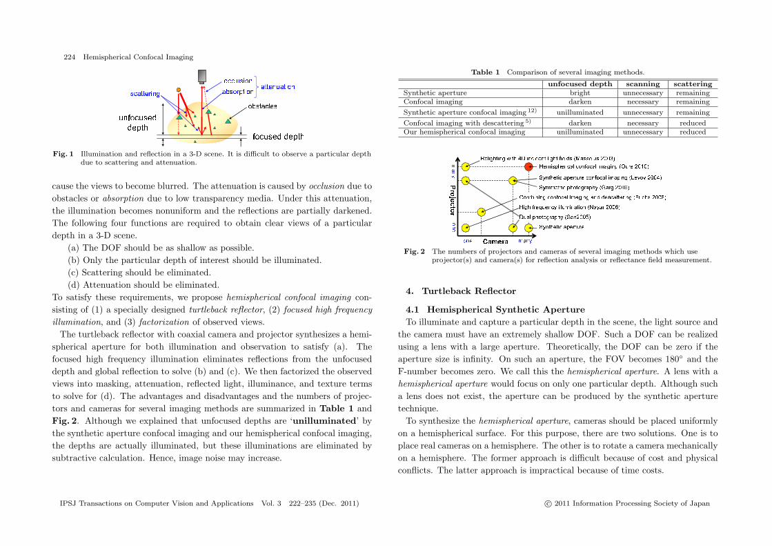
Fig. 1 Illumination and reflection in a 3-D scene. It is difficult to observe a particular depthdue to scattering and attenuation.
cause the views to become blurred. The attenuation is caused by occlusion due toobstacles or absorption due to low transparency media. Under this attenuation,the illumination becomes nonuniform and the reflections are partially darkened.The following four functions are required to obtain clear views of a particulardepth in a 3-D scene.
(a) The DOF should be as shallow as possible.(b) Only the particular depth of interest should be illuminated.(c) Scattering should be eliminated.(d) Attenuation should be eliminated.
To satisfy these requirements, we propose hemispherical confocal imaging con-sisting of (1) a specially designed turtleback reflector, (2) focused high frequencyillumination, and (3) factorization of observed views.
The turtleback reflector with coaxial camera and projector synthesizes a hemi-spherical aperture for both illumination and observation to satisfy (a). Thefocused high frequency illumination eliminates reflections from the unfocuseddepth and global reflection to solve (b) and (c). We then factorized the observedviews into masking, attenuation, reflected light, illuminance, and texture termsto solve for (d). The advantages and disadvantages and the numbers of projec-tors and cameras for several imaging methods are summarized in Table 1 andFig. 2. Although we explained that unfocused depths are ‘unilluminated’ bythe synthetic aperture confocal imaging and our hemispherical confocal imaging,the depths are actually illuminated, but these illuminations are eliminated bysubtractive calculation. Hence, image noise may increase.
Table 1 Comparison of several imaging methods.
unfocused depth scanning scatteringSynthetic aperture bright unnecessary remainingConfocal imaging darken necessary remaining
Synthetic aperture confocal imaging 12) unilluminated unnecessary remaining
Confocal imaging with descattering 5) darken necessary reducedOur hemispherical confocal imaging unilluminated unnecessary reduced
Fig. 2 The numbers of projectors and cameras of several imaging methods which useprojector(s) and camera(s) for reflection analysis or reflectance field measurement.
4. Turtleback Reflector
4.1 Hemispherical Synthetic ApertureTo illuminate and capture a particular depth in the scene, the light source and
the camera must have an extremely shallow DOF. Such a DOF can be realizedusing a lens with a large aperture. Theoretically, the DOF can be zero if theaperture size is infinity. On such an aperture, the FOV becomes 180◦ and theF-number becomes zero. We call this the hemispherical aperture. A lens with ahemispherical aperture would focus on only one particular depth. Although sucha lens does not exist, the aperture can be produced by the synthetic aperturetechnique.
To synthesize the hemispherical aperture, cameras should be placed uniformlyon a hemispherical surface. For this purpose, there are two solutions. One is toplace real cameras on a hemisphere. The other is to rotate a camera mechanicallyon a hemisphere. The former approach is difficult because of cost and physicalconflicts. The latter approach is impractical because of time costs.
IPSJ Transactions on Computer Vision and Applications Vol. 3 222–235 (Dec. 2011) c© 2011 Information Processing Society of Japan
225 Hemispherical Confocal Imaging
To realize the hemispherical aperture, we used planar mirrors. By combininga camera with many planar mirrors, a number of virtual cameras with low reso-lution can be generated and can then capture the scene from various directions.
Views from the virtual cameras are included in a view from the real camera.Hence, the corresponding region for each virtual camera must be cropped andwarped to obtain images. The geometric calibration of the virtual cameras isperformed by finding corresponding points in a captured image using the realcamera. The geometric conversion from the real camera to virtual cameras canbe achieved using simple homography. The pixel intensities of the virtual imageare resampled from the captured image.
4.2 Mirror DesignFor the hemispherical synthetic aperture, the planar mirrors should be posi-
tioned, so that they place the virtual cameras on a hemisphere. The distancebetween the target and each virtual camera should be constant. The approachused to produce such an arrangement of planar mirrors varies between the dif-ferent projections of the real camera.
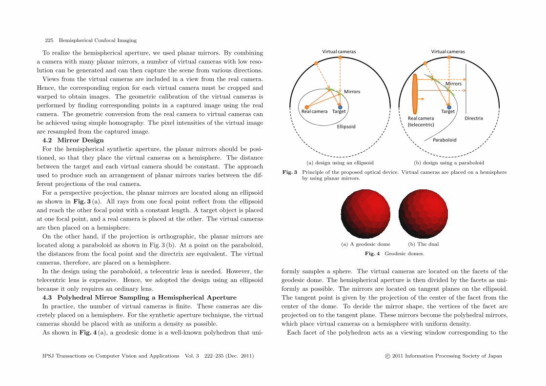
For a perspective projection, the planar mirrors are located along an ellipsoidas shown in Fig. 3 (a). All rays from one focal point reflect from the ellipsoidand reach the other focal point with a constant length. A target object is placedat one focal point, and a real camera is placed at the other. The virtual camerasare then placed on a hemisphere.
On the other hand, if the projection is orthographic, the planar mirrors arelocated along a paraboloid as shown in Fig. 3 (b). At a point on the paraboloid,the distances from the focal point and the directrix are equivalent. The virtualcameras, therefore, are placed on a hemisphere.
In the design using the paraboloid, a telecentric lens is needed. However, thetelecentric lens is expensive. Hence, we adopted the design using an ellipsoidbecause it only requires an ordinary lens.
4.3 Polyhedral Mirror Sampling a Hemispherical ApertureIn practice, the number of virtual cameras is finite. These cameras are dis-
cretely placed on a hemisphere. For the synthetic aperture technique, the virtualcameras should be placed with as uniform a density as possible.
As shown in Fig. 4 (a), a geodesic dome is a well-known polyhedron that uni-
(a) design using an ellipsoid (b) design using a paraboloid
Fig. 3 Principle of the proposed optical device. Virtual cameras are placed on a hemisphereby using planar mirrors.
(a) A geodesic dome (b) The dual
Fig. 4 Geodesic domes.
formly samples a sphere. The virtual cameras are located on the facets of thegeodesic dome. The hemispherical aperture is then divided by the facets as uni-formly as possible. The mirrors are located on tangent planes on the ellipsoid.The tangent point is given by the projection of the center of the facet from thecenter of the dome. To decide the mirror shape, the vertices of the facet areprojected on to the tangent plane. These mirrors become the polyhedral mirrors,which place virtual cameras on a hemisphere with uniform density.
Each facet of the polyhedron acts as a viewing window corresponding to the
IPSJ Transactions on Computer Vision and Applications Vol. 3 222–235 (Dec. 2011) c© 2011 Information Processing Society of Japan

226 Hemispherical Confocal Imaging
Fig. 5 Design of polyhedral mirrors using two ellipsoids.
virtual camera. A region commonly observed from all virtual cameras is definedby a logical AND of all the views of the virtual camera. That is, the shape of afacet should be close to a circle in order to observe a large area. Therefore, weused the dual geodesic dome shown in Fig. 4 (b) instead of the original geodesicdome, because the dual dome has pentagonal and hexagonal facets, while theoriginal geodesic dome had triangular facets.
4.4 Design of the Turtleback ReflectorWe now show an implementation of our polyhedral mirror. We first decided
on the number of mirrors. The geodesic dome is made by dividing 20 facets ofan icosahedron into 20 × 4k (k ∈ N) facets. The number of facets of the dualdome is then N = 10 × 4k + 2. We set k = 2 and N = 162. The upper halfhemisphere consists of 81 facets. However, 81 facets do not completely cover theupper hemisphere. Hence we added 10 horizontal facets, which are located at theborder of the upper and lower hemispheres. In total we used 91 facets.
In the design shown in Fig. 3 (a), the target object occludes some mirrors.Hence, we combined two ellipsoids as shown in Fig. 5. In this design, the twopolyhedral mirrors place the virtual cameras over the whole surface of the hemi-sphere.
We designed one polyhedral mirror because pairs of polyhedral mirrors aresymmetrical. To fix the mirror patches, we designed a frame as shown in Fig. 6.
(a) front view (b) bottom view (c) dimensions
Fig. 6 Design of the frame for the turtleback reflector.
Fig. 7 Turtleback reflector.
This frame is made by stereolithography and planar mirror patches are attachedto the frame. Fifty mirror patches completely cover half of the hemisphere. Theframe with mirror patches is the turtleback reflector as shown in Fig. 7.
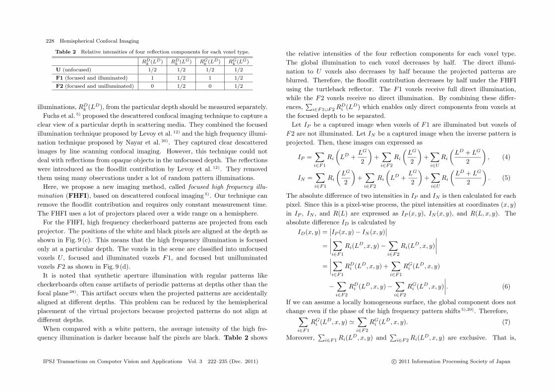
4.5 Total Optical DeviceIn this research, we combine the turtleback reflector with a coaxial pairing of
a high-resolution camera (PointGrey, Grass-50S5C, 2,448 × 2,048) and a smallprojector (KAIREN Projector X Pro920, 640 × 480) using a beam splitter asshown in Fig. 8.
The device is designed to measure a small area of 6 × 6 mm. By resamplingthe captured image using a real camera, images of the virtual cameras whoseresolution is 60 × 60 pixels are generated. For a virtual projector, we resample
IPSJ Transactions on Computer Vision and Applications Vol. 3 222–235 (Dec. 2011) c© 2011 Information Processing Society of Japan
227 Hemispherical Confocal Imaging
Fig. 8 Total optical device for hemispherical confocal imaging.
the target area using a 20 × 20 format. Hence, the resolution of the virtualprojector corresponds to 20 × 20 pixels.
Theoretically, both the illumination and observation can be focused only on aparticular depth in the scene and the DOF becomes zero. However, we imple-mented only half of the whole turtleback reflector. Therefore, strictly the DOFof our prototype system is not zero but shallow.
5. Focused High Frequency Illumination
5.1 Illumination and Reflection in a 3-D SceneTo analyze the reflectance field in a 3-D scene, we need to know how light il-
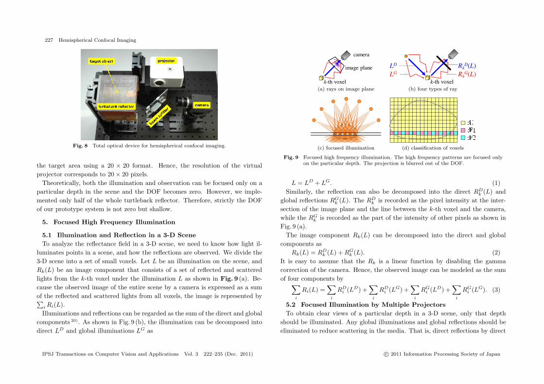
luminates points in a scene, and how the reflections are observed. We divide the3-D scene into a set of small voxels. Let L be an illumination on the scene, andRk(L) be an image component that consists of a set of reflected and scatteredlights from the k-th voxel under the illumination L as shown in Fig. 9 (a). Be-cause the observed image of the entire scene by a camera is expressed as a sumof the reflected and scattered lights from all voxels, the image is represented by∑
i Ri(L).Illuminations and reflections can be regarded as the sum of the direct and global
components 20). As shown in Fig. 9 (b), the illumination can be decomposed intodirect LD and global illuminations LG as
(a) rays on image plane (b) four types of ray
(c) focused illumination (d) classification of voxels
Fig. 9 Focused high frequency illumination. The high frequency patterns are focused onlyon the particular depth. The projection is blurred out of the DOF.
L = LD + LG. (1)Similarly, the reflection can also be decomposed into the direct RD
k (L) andglobal reflections RG
k (L). The RDk is recorded as the pixel intensity at the inter-
section of the image plane and the line between the k-th voxel and the camera,while the RG
k is recorded as the part of the intensity of other pixels as shown inFig. 9 (a).
The image component Rk(L) can be decomposed into the direct and globalcomponents as
Rk(L) = RDk (L) + RG
k (L). (2)It is easy to assume that the Rk is a linear function by disabling the gammacorrection of the camera. Hence, the observed image can be modeled as the sumof four components by∑
i
Ri(L) =∑
i
RDi (LD) +
∑i
RDi (LG) +
∑i
RGi (LD) +
∑i
RGi (LG). (3)
5.2 Focused Illumination by Multiple ProjectorsTo obtain clear views of a particular depth in a 3-D scene, only that depth
should be illuminated. Any global illuminations and global reflections should beeliminated to reduce scattering in the media. That is, direct reflections by direct
IPSJ Transactions on Computer Vision and Applications Vol. 3 222–235 (Dec. 2011) c© 2011 Information Processing Society of Japan
228 Hemispherical Confocal Imaging
Table 2 Relative intensities of four reflection components for each voxel type.
RDk (LD) RD
k (LG) RGk (LD) RG
k (LG)
U (unfocused) 1/2 1/2 1/2 1/2
F1 (focused and illuminated) 1 1/2 1 1/2
F2 (focused and unilluminated) 0 1/2 0 1/2
illuminations, RDk (LD), from the particular depth should be measured separately.
Fuchs et al. 5) proposed the descattered confocal imaging technique to capture aclear view of a particular depth in scattering media. They combined the focusedillumination technique proposed by Levoy et al. 12) and the high frequency illumi-nation technique proposed by Nayar et al. 20). They captured clear descatteredimages by line scanning confocal imaging. However, this technique could notdeal with reflections from opaque objects in the unfocused depth. The reflectionswere introduced as the floodlit contribution by Levoy et al. 12). They removedthem using many observations under a lot of random pattern illuminations.
Here, we propose a new imaging method, called focused high frequency illu-mination (FHFI), based on descattered confocal imaging 5). Our technique canremove the floodlit contribution and requires only constant measurement time.The FHFI uses a lot of projectors placed over a wide range on a hemisphere.
For the FHFI, high frequency checkerboard patterns are projected from eachprojector. The positions of the white and black pixels are aligned at the depth asshown in Fig. 9 (c). This means that the high frequency illumination is focusedonly at a particular depth. The voxels in the scene are classified into unfocusedvoxels U , focused and illuminated voxels F1, and focused but unilluminatedvoxels F2 as shown in Fig. 9 (d).
It is noted that synthetic aperture illumination with regular patterns likecheckerboards often cause artifacts of periodic patterns at depths other than thefocal plane 28). This artifact occurs when the projected patterns are accidentallyaligned at different depths. This problem can be reduced by the hemisphericalplacement of the virtual projectors because projected patterns do not align atdifferent depths.
When compared with a white pattern, the average intensity of the high fre-quency illumination is darker because half the pixels are black. Table 2 shows
the relative intensities of the four reflection components for each voxel type.The global illumination to each voxel decreases by half. The direct illumi-nation to U voxels also decreases by half because the projected patterns areblurred. Therefore, the floodlit contribution decreases by half under the FHFIusing the turtleback reflector. The F1 voxels receive full direct illumination,while the F2 voxels receive no direct illumination. By combining these differ-ences,
∑i∈F1∪F2 RD
i (LD) which enables only direct components from voxels atthe focused depth to be separated.
Let IP be a captured image when voxels of F1 are illuminated but voxels ofF2 are not illuminated. Let IN be a captured image when the inverse pattern isprojected. Then, these images can expressed as
IP =∑i∈F1
Ri
(LD +
LG
2
)+
∑i∈F2
Ri
(LG
2
)+
∑i∈U
Ri
(LD + LG
2
), (4)
IN =∑i∈F1
Ri
(LG
2
)+
∑i∈F2
Ri
(LD +
LG
2
)+
∑i∈U
Ri
(LD + LG
2
). (5)
The absolute difference of two intensities in IP and IN is then calculated for eachpixel. Since this is a pixel-wise process, the pixel intensities at coordinates (x, y)in IP , IN , and R(L) are expressed as IP (x, y), IN (x, y), and R(L, x, y). Theabsolute difference ID is calculated by
ID(x, y) =∣∣IP (x, y) − IN (x, y)
∣∣=
∣∣∣∣∑i∈F1
Ri(LD, x, y) −∑i∈F2
Ri(LD, x, y)∣∣∣∣
=∣∣∣∣∑i∈F1
RDi (LD, x, y) +
∑i∈F1
RGi (LD, x, y)
−∑i∈F2
RDi (LD, x, y) −
∑i∈F2
RGi (LD, x, y)
∣∣∣∣. (6)
If we can assume a locally homogeneous surface, the global component does notchange even if the phase of the high frequency pattern shifts 5),20). Therefore,∑
i∈F1
RGi (LD, x, y) �
∑i∈F2
RGi (LD, x, y). (7)
Moreover,∑
i∈F1 Ri(LD, x, y) and∑
i∈F2 Ri(LD, x, y) are exclusive. That is,
IPSJ Transactions on Computer Vision and Applications Vol. 3 222–235 (Dec. 2011) c© 2011 Information Processing Society of Japan
229 Hemispherical Confocal Imaging
when the voxels of F1 are illuminated, the former becomes large while the latterbecomes zero and vice versa. Hence,
ID(x, y) =∣∣∣∣∑i∈F1
RDi (LD, x, y) −
∑i∈F2
RDi (LD, x, y)
∣∣∣∣=
∑i∈F1
RDi (LD, x, y) +
∑i∈F2
RDi (LD, x, y)
=∑
i∈F1∪F2
RDi (LD, x, y). (8)
This means that only the particular depth (F1∪F2) can be directly illuminatedwithout global illuminations, and only the direct reflections can be measuredwithout global reflections. As shown in Table 1, our method does not illuminatethe unfocused depth. Because no scanning is necessary, the measurement is fast.Furthermore, scattering, which is a major global component in translucent media,is eliminated.
6. Factorization of the Observed Views
6.1 Attenuation of Incident and Reflected LightBy the FHFI introduced in the previous section, only the focused depth is
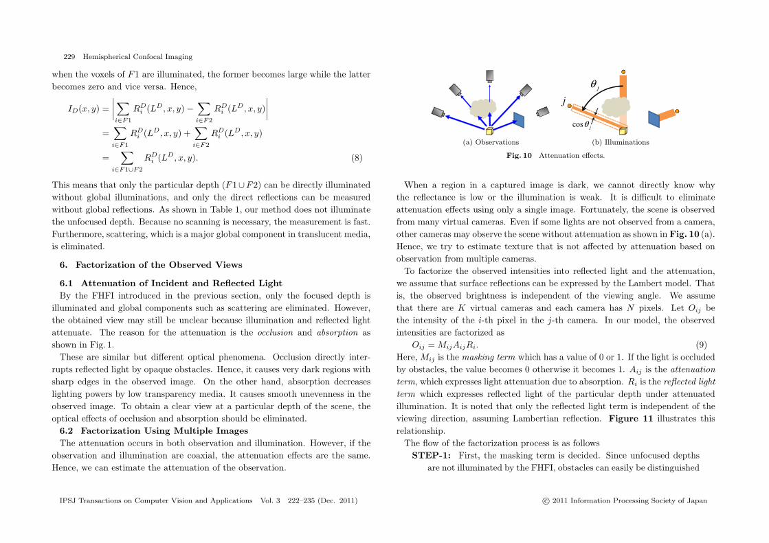
illuminated and global components such as scattering are eliminated. However,the obtained view may still be unclear because illumination and reflected lightattenuate. The reason for the attenuation is the occlusion and absorption asshown in Fig. 1.
These are similar but different optical phenomena. Occlusion directly inter-rupts reflected light by opaque obstacles. Hence, it causes very dark regions withsharp edges in the observed image. On the other hand, absorption decreaseslighting powers by low transparency media. It causes smooth unevenness in theobserved image. To obtain a clear view at a particular depth of the scene, theoptical effects of occlusion and absorption should be eliminated.
6.2 Factorization Using Multiple ImagesThe attenuation occurs in both observation and illumination. However, if the
observation and illumination are coaxial, the attenuation effects are the same.Hence, we can estimate the attenuation of the observation.
(a) Observations (b) Illuminations
Fig. 10 Attenuation effects.
When a region in a captured image is dark, we cannot directly know whythe reflectance is low or the illumination is weak. It is difficult to eliminateattenuation effects using only a single image. Fortunately, the scene is observedfrom many virtual cameras. Even if some lights are not observed from a camera,other cameras may observe the scene without attenuation as shown in Fig. 10 (a).Hence, we try to estimate texture that is not affected by attenuation based onobservation from multiple cameras.
To factorize the observed intensities into reflected light and the attenuation,we assume that surface reflections can be expressed by the Lambert model. Thatis, the observed brightness is independent of the viewing angle. We assumethat there are K virtual cameras and each camera has N pixels. Let Oij bethe intensity of the i-th pixel in the j-th camera. In our model, the observedintensities are factorized as
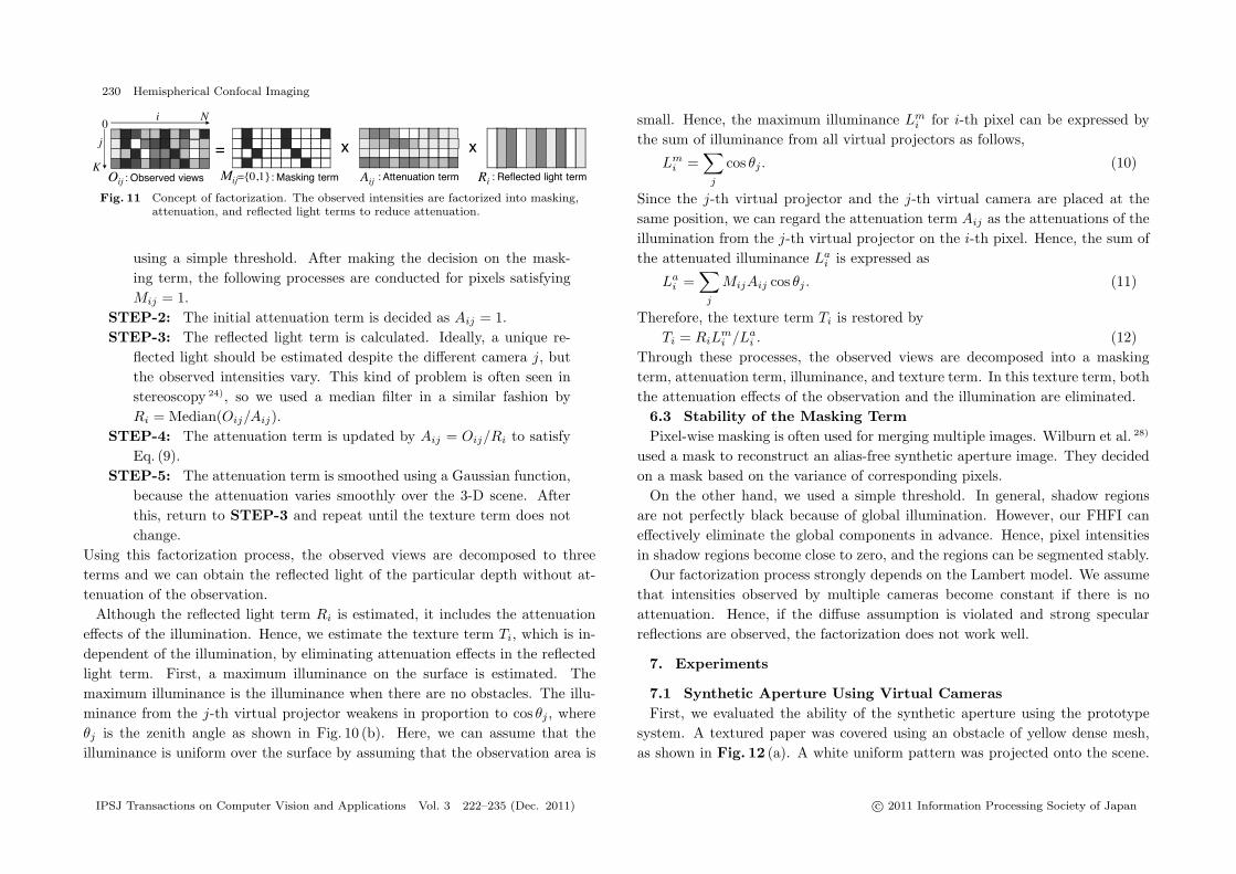
Oij = MijAijRi. (9)Here, Mij is the masking term which has a value of 0 or 1. If the light is occludedby obstacles, the value becomes 0 otherwise it becomes 1. Aij is the attenuationterm, which expresses light attenuation due to absorption. Ri is the reflected lightterm which expresses reflected light of the particular depth under attenuatedillumination. It is noted that only the reflected light term is independent of theviewing direction, assuming Lambertian reflection. Figure 11 illustrates thisrelationship.
The flow of the factorization process is as followsSTEP-1: First, the masking term is decided. Since unfocused depths
are not illuminated by the FHFI, obstacles can easily be distinguished
IPSJ Transactions on Computer Vision and Applications Vol. 3 222–235 (Dec. 2011) c© 2011 Information Processing Society of Japan
230 Hemispherical Confocal Imaging
Fig. 11 Concept of factorization. The observed intensities are factorized into masking,attenuation, and reflected light terms to reduce attenuation.
using a simple threshold. After making the decision on the mask-ing term, the following processes are conducted for pixels satisfyingMij = 1.
STEP-2: The initial attenuation term is decided as Aij = 1.STEP-3: The reflected light term is calculated. Ideally, a unique re-
flected light should be estimated despite the different camera j, butthe observed intensities vary. This kind of problem is often seen instereoscopy 24), so we used a median filter in a similar fashion byRi = Median(Oij/Aij).
STEP-4: The attenuation term is updated by Aij = Oij/Ri to satisfyEq. (9).
STEP-5: The attenuation term is smoothed using a Gaussian function,because the attenuation varies smoothly over the 3-D scene. Afterthis, return to STEP-3 and repeat until the texture term does notchange.
Using this factorization process, the observed views are decomposed to threeterms and we can obtain the reflected light of the particular depth without at-tenuation of the observation.
Although the reflected light term Ri is estimated, it includes the attenuationeffects of the illumination. Hence, we estimate the texture term Ti, which is in-dependent of the illumination, by eliminating attenuation effects in the reflectedlight term. First, a maximum illuminance on the surface is estimated. Themaximum illuminance is the illuminance when there are no obstacles. The illu-minance from the j-th virtual projector weakens in proportion to cos θj , whereθj is the zenith angle as shown in Fig. 10 (b). Here, we can assume that theilluminance is uniform over the surface by assuming that the observation area is
small. Hence, the maximum illuminance Lmi for i-th pixel can be expressed by
the sum of illuminance from all virtual projectors as follows,
Lmi =
∑j
cos θj . (10)
Since the j-th virtual projector and the j-th virtual camera are placed at thesame position, we can regard the attenuation term Aij as the attenuations of theillumination from the j-th virtual projector on the i-th pixel. Hence, the sum ofthe attenuated illuminance La
i is expressed as
Lai =
∑j
MijAij cos θj . (11)
Therefore, the texture term Ti is restored byTi = RiL
mi /La
i . (12)Through these processes, the observed views are decomposed into a maskingterm, attenuation term, illuminance, and texture term. In this texture term, boththe attenuation effects of the observation and the illumination are eliminated.
6.3 Stability of the Masking TermPixel-wise masking is often used for merging multiple images. Wilburn et al. 28)
used a mask to reconstruct an alias-free synthetic aperture image. They decidedon a mask based on the variance of corresponding pixels.
On the other hand, we used a simple threshold. In general, shadow regionsare not perfectly black because of global illumination. However, our FHFI caneffectively eliminate the global components in advance. Hence, pixel intensitiesin shadow regions become close to zero, and the regions can be segmented stably.
Our factorization process strongly depends on the Lambert model. We assumethat intensities observed by multiple cameras become constant if there is noattenuation. Hence, if the diffuse assumption is violated and strong specularreflections are observed, the factorization does not work well.
7. Experiments
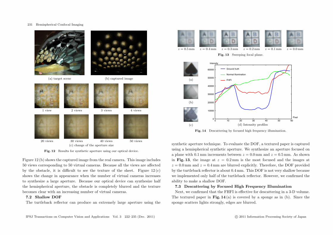
7.1 Synthetic Aperture Using Virtual CamerasFirst, we evaluated the ability of the synthetic aperture using the prototype
system. A textured paper was covered using an obstacle of yellow dense mesh,as shown in Fig. 12 (a). A white uniform pattern was projected onto the scene.
IPSJ Transactions on Computer Vision and Applications Vol. 3 222–235 (Dec. 2011) c© 2011 Information Processing Society of Japan
231 Hemispherical Confocal Imaging
(a) target scene (b) captured image
1 view 2 views 3 views 4 views
20 views 30 views 40 views 50 views
(c) change of the aperture size
Fig. 12 Results for synthetic aperture using our optical device.
Figure 12 (b) shows the captured image from the real camera. This image includes50 views corresponding to 50 virtual cameras. Because all the views are affectedby the obstacle, it is difficult to see the texture of the sheet. Figure 12 (c)shows the change in appearance when the number of virtual cameras increasesto synthesize a large aperture. Because our optical device can synthesize halfthe hemispherical aperture, the obstacle is completely blurred and the texturebecomes clear with an increasing number of virtual cameras.
7.2 Shallow DOFThe turtleback reflector can produce an extremely large aperture using the
z = 0.5 mm z = 0.4 mm z = 0.3 mm z = 0.2 mm z = 0.1 mm z = 0.0 mm
Fig. 13 Sweeping focal plane.
(a)
(b)
(c) (d) Intensity profiles
Fig. 14 Descattering by focused high frequency illumination.
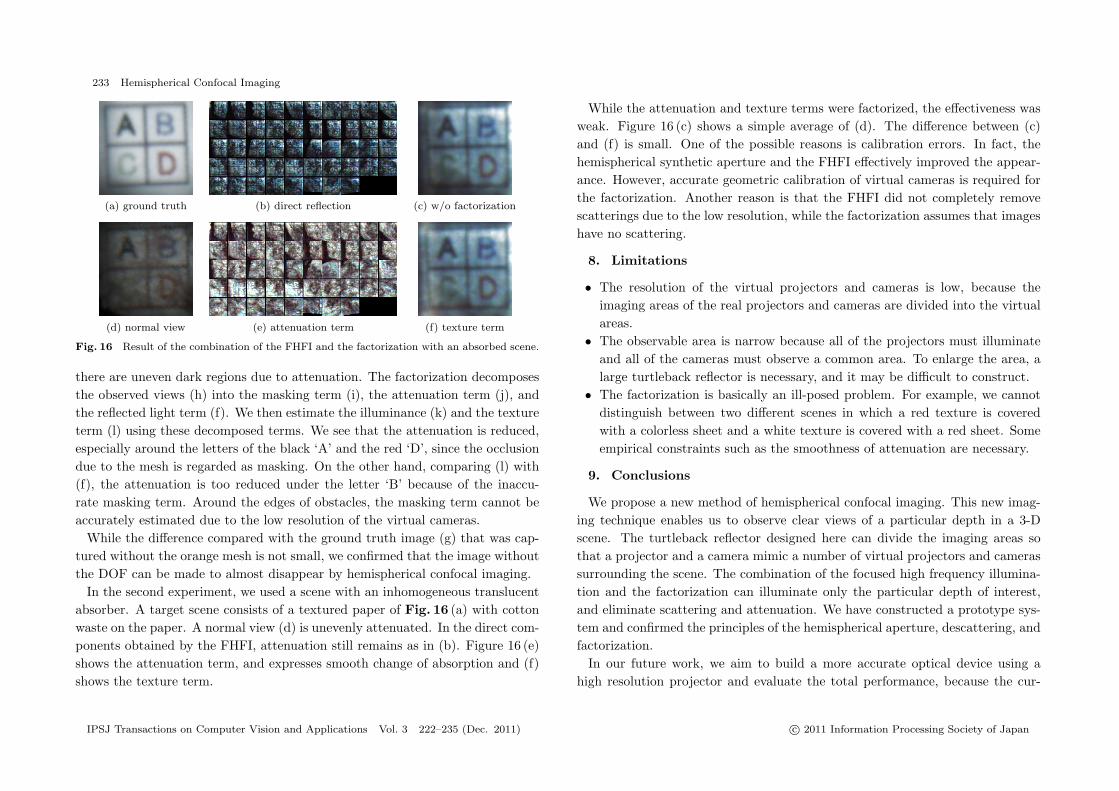
synthetic aperture technique. To evaluate the DOF, a textured paper is capturedusing a hemispherical synthetic aperture. We synthesize an aperture focused ona plane with 0.1 mm increments between z = 0.0 mm and z = 0.5 mm. As shownin Fig. 13, the image at z = 0.2 mm is the most focused and the images atz = 0.0 mm and z = 0.4 mm are blurred explicitly. Therefore, the DOF providedby the turtleback reflector is about 0.4 mm. This DOF is not very shallow becausewe implemented only half of the turtleback reflector. However, we confirmed theability to make a shallow DOF.
7.3 Descattering by Focused High Frequency IlluminationNext, we confirmed that the FHFI is effective for descattering in a 3-D volume.
The textured paper in Fig. 14 (a) is covered by a sponge as in (b). Since thesponge scatters lights strongly, edges are blurred.
IPSJ Transactions on Computer Vision and Applications Vol. 3 222–235 (Dec. 2011) c© 2011 Information Processing Society of Japan

232 Hemispherical Confocal Imaging
(a) scene (b) views under normal illumination (c) syntheticaperture
(d) FHFI w/ofactorization
(e) confocalimaging
(f) reflectedlight term
(g) groundtruth
(h) direct reflection (i) masking term (j) attenuation term (k) illuminance (l) texture term
Fig. 15 Result of the combination of the FHFI and the factorization with an occluded scene.
In theory, only two illumination patterns are needed for the FHFI. However,the illuminated pattern becomes blurred at the edges. Hence, we used checkeredpatterns, in which white and black are replaced every three pixels and shiftedthe pattern by one pixel. In total, 18 illumination patterns are projected fromthe virtual projectors so that these patterns are aligned on the paper. As Nayaret al. 20) did, we took maximum and minimum intensities for each pixel positionin the 18 images. Then, the difference image can be obtained.
Figure 14 (c) shows the direct component obtained by the FHFI. We can seethat scattering in the 3-D scene is reduced and the contrast is improved. Toshow how much the contrast was improved, we analyzed the intensity profiles ofthe images as shown in Fig. 14 (d). This graph shows intensity profiles along ahorizontal line at the mid height of the images. The central region from 20 to 40corresponds to the black part of the spade figure. We can see that the contrastwas improved by descattering. The descattering effect is not perfect, which isattributed to the low resolution of the virtual projectors in the current prototypesystem.
7.4 Factorization of the Observed ViewsWe confirmed the ability to visualize a particular depth in a 3-D scene by
combining the FHFI and the factorization. The factorization reduces attenuationeffects of occlusion and absorption. Hence, we evaluated them separately.
In the first experiment, we used a scene with occluders. Figure 15 (a) showsthe scene where an orange mesh covers a textured paper, and (b) shows all viewsfrom the virtual cameras under normal illumination �1. By simply averaging theseviews, a synthetic aperture image can be generated, as shown in (c). Althoughthe obstacle is blurred, the orange color of the mesh affects the paper. Confocalimaging 16) can generate a better image as shown in (e) because the orange meshis less illuminated.
The mesh becomes dark under the FHFI because it is not illuminated, whilethe paper is bright, as shown in (h). By averaging these views, the dark meshis blurred and the orange color correctly disappears, as shown in (d). However,
�1 Although there are 50 mirror patches, only 48 patches were used because two patches weremisaligned.
IPSJ Transactions on Computer Vision and Applications Vol. 3 222–235 (Dec. 2011) c© 2011 Information Processing Society of Japan
233 Hemispherical Confocal Imaging
(a) ground truth (b) direct reflection (c) w/o factorization
(d) normal view (e) attenuation term (f) texture term
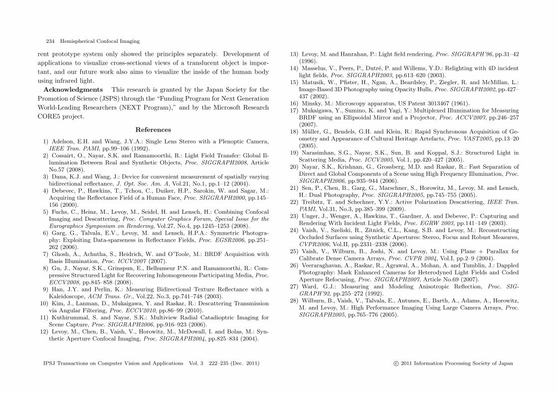
Fig. 16 Result of the combination of the FHFI and the factorization with an absorbed scene.
there are uneven dark regions due to attenuation. The factorization decomposesthe observed views (h) into the masking term (i), the attenuation term (j), andthe reflected light term (f). We then estimate the illuminance (k) and the textureterm (l) using these decomposed terms. We see that the attenuation is reduced,especially around the letters of the black ‘A’ and the red ‘D’, since the occlusiondue to the mesh is regarded as masking. On the other hand, comparing (l) with(f), the attenuation is too reduced under the letter ‘B’ because of the inaccu-rate masking term. Around the edges of obstacles, the masking term cannot beaccurately estimated due to the low resolution of the virtual cameras.
While the difference compared with the ground truth image (g) that was cap-tured without the orange mesh is not small, we confirmed that the image withoutthe DOF can be made to almost disappear by hemispherical confocal imaging.
In the second experiment, we used a scene with an inhomogeneous translucentabsorber. A target scene consists of a textured paper of Fig. 16 (a) with cottonwaste on the paper. A normal view (d) is unevenly attenuated. In the direct com-ponents obtained by the FHFI, attenuation still remains as in (b). Figure 16 (e)shows the attenuation term, and expresses smooth change of absorption and (f)shows the texture term.
While the attenuation and texture terms were factorized, the effectiveness wasweak. Figure 16 (c) shows a simple average of (d). The difference between (c)and (f) is small. One of the possible reasons is calibration errors. In fact, thehemispherical synthetic aperture and the FHFI effectively improved the appear-ance. However, accurate geometric calibration of virtual cameras is required forthe factorization. Another reason is that the FHFI did not completely removescatterings due to the low resolution, while the factorization assumes that imageshave no scattering.
8. Limitations
• The resolution of the virtual projectors and cameras is low, because theimaging areas of the real projectors and cameras are divided into the virtualareas.
• The observable area is narrow because all of the projectors must illuminateand all of the cameras must observe a common area. To enlarge the area, alarge turtleback reflector is necessary, and it may be difficult to construct.
• The factorization is basically an ill-posed problem. For example, we cannotdistinguish between two different scenes in which a red texture is coveredwith a colorless sheet and a white texture is covered with a red sheet. Someempirical constraints such as the smoothness of attenuation are necessary.
9. Conclusions
We propose a new method of hemispherical confocal imaging. This new imag-ing technique enables us to observe clear views of a particular depth in a 3-Dscene. The turtleback reflector designed here can divide the imaging areas sothat a projector and a camera mimic a number of virtual projectors and camerassurrounding the scene. The combination of the focused high frequency illumina-tion and the factorization can illuminate only the particular depth of interest,and eliminate scattering and attenuation. We have constructed a prototype sys-tem and confirmed the principles of the hemispherical aperture, descattering, andfactorization.
In our future work, we aim to build a more accurate optical device using ahigh resolution projector and evaluate the total performance, because the cur-
IPSJ Transactions on Computer Vision and Applications Vol. 3 222–235 (Dec. 2011) c© 2011 Information Processing Society of Japan
234 Hemispherical Confocal Imaging
rent prototype system only showed the principles separately. Development ofapplications to visualize cross-sectional views of a translucent object is impor-tant, and our future work also aims to visualize the inside of the human bodyusing infrared light.
Acknowledgments This research is granted by the Japan Society for thePromotion of Science (JSPS) through the “Funding Program for Next GenerationWorld-Leading Researchers (NEXT Program),” and by the Microsoft ResearchCORE5 project.
References
1) Adelson, E.H. and Wang, J.Y.A.: Single Lens Stereo with a Plenoptic Camera,IEEE Tran. PAMI, pp.99–106 (1992).
2) Cossairt, O., Nayar, S.K. and Ramamoorthi, R.: Light Field Transfer: Global Il-lumination Between Real and Synthetic Objects, Proc. SIGGRAPH2008, ArticleNo.57 (2008).
3) Dana, K.J. and Wang, J.: Device for convenient measurement of spatially varyingbidirectional reflectance, J. Opt. Soc. Am. A, Vol.21, No.1, pp.1–12 (2004).
4) Debevec, P., Hawkins, T., Tchou, C., Duiker, H.P., Sarokin, W. and Sagar, M.:Acquiring the Reflectance Field of a Human Face, Proc. SIGGRAPH2000, pp.145–156 (2000).
5) Fuchs, C., Heinz, M., Levoy, M., Seidel, H. and Lensch, H.: Combining ConfocalImaging and Descattering, Proc. Computer Graphics Forum, Special Issue for theEurographics Symposium on Rendering, Vol.27, No.4, pp.1245–1253 (2008).
6) Garg, G., Talvala, E.V., Levoy, M. and Lensch, H.P.A.: Symmetric Photogra-phy: Exploiting Data-sparseness in Reflectance Fields, Proc. EGSR2006, pp.251–262 (2006).
7) Ghosh, A., Achutha, S., Heidrich, W. and O’Toole, M.: BRDF Acquisition withBasis Illumination, Proc. ICCV2007 (2007).
8) Gu, J., Nayar, S.K., Grinspun, E., Belhumeur P.N. and Ramamoorthi, R.: Com-pressive Structured Light for Recovering Inhomogeneous Participating Media, Proc.ECCV2008, pp.845–858 (2008).
9) Han, J.Y. and Perlin, K.: Measuring Bidirectional Texture Reflectance with aKaleidoscope, ACM Trans. Gr., Vol.22, No.3, pp.741–748 (2003).
10) Kim, J., Lanman, D., Mukaigawa, Y. and Raskar, R.: Descattering Transmissionvia Angular Filtering, Proc. ECCV2010, pp.86–99 (2010).
11) Kuthirummal, S. and Nayar, S.K.: Multiview Radial Catadioptric Imaging forScene Capture, Proc. SIGGRAPH2006, pp.916–923 (2006).
12) Levoy, M., Chen, B., Vaish, V., Horowitz, M., McDowall, I. and Bolas, M.: Syn-thetic Aperture Confocal Imaging, Proc. SIGGRAPH2004, pp.825–834 (2004).
13) Levoy, M. and Hanrahan, P.: Light field rendering, Proc. SIGGRAPH’96, pp.31–42(1996).
14) Masselus, V., Peers, P., Dutre, P. and Willems, Y.D.: Relighting with 4D incidentlight fields, Proc. SIGGRAPH2003, pp.613–620 (2003).
15) Matusik, W., Pfister, H., Ngan, A., Beardsley, P., Ziegler, R. and McMillan, L.:Image-Based 3D Photography using Opacity Hulls, Proc. SIGGRAPH2002, pp.427–437 (2002).
16) Minsky, M.: Microscopy apparatus, US Patent 3013467 (1961).17) Mukaigawa, Y., Sumino, K. and Yagi, Y.: Multiplexed Illumination for Measuring
BRDF using an Ellipsoidal Mirror and a Projector, Proc. ACCV2007, pp.246–257(2007).
18) Muller, G., Bendels, G.H. and Klein, R.: Rapid Synchronous Acquisition of Ge-ometry and Appearance of Cultural Heritage Artefacts, Proc. VAST2005, pp.13–20(2005).
19) Narasimhan, S.G., Nayar, S.K., Sun, B. and Koppal, S.J.: Structured Light inScattering Media, Proc. ICCV2005, Vol.1, pp.420–427 (2005).
20) Nayar, S.K., Krishnan, G., Grossberg, M.D. and Raskar, R.: Fast Separation ofDirect and Global Components of a Scene using High Frequency Illumination, Proc.SIGGRAPH2006, pp.935–944 (2006).
21) Sen, P., Chen, B., Garg, G., Marschner, S., Horowitz, M., Levoy, M. and Lensch,H.: Dual Photography, Proc. SIGGRAPH2005, pp.745–755 (2005).
22) Treibitz, T. and Schechner, Y.Y.: Active Polarization Descattering, IEEE Tran.PAMI, Vol.31, No.3, pp.385–399 (2009).
23) Unger, J., Wenger, A., Hawkins, T., Gardner, A. and Debevec, P.: Capturing andRendering With Incident Light Fields, Proc. EGRW 2003, pp.141–149 (2003).
24) Vaish, V., Szeliski, R., Zitnick, C.L., Kang, S.B. and Levoy, M.: ReconstructingOccluded Surfaces using Synthetic Apertures: Stereo, Focus and Robust Measures,CVPR2006, Vol.II, pp.2331–2338 (2006).
25) Vaish, V., Wilburn, B., Joshi, N. and Levoy, M.: Using Plane + Parallax forCalibrate Dense Camera Arrays, Proc. CVPR 2004, Vol.I, pp.2–9 (2004).
26) Veeraraghavan, A., Raskar, R., Agrawal, A., Mohan, A. and Tumblin, J.: DappledPhotography: Mask Enhanced Cameras for Heterodyned Light Fields and CodedAperture Refocusing, Proc. SIGGRAPH2007, Article No.69 (2007).
27) Ward, G.J.: Measuring and Modeling Anisotropic Reflection, Proc. SIG-GRAPH’92, pp.255–272 (1992).
28) Wilburn, B., Vaish, V., Talvala, E., Antunes, E., Barth, A., Adams, A., Horowitz,M. and Levoy, M.: High Performance Imaging Using Large Camera Arrays, Proc.SIGGRAPH2005, pp.765–776 (2005).
IPSJ Transactions on Computer Vision and Applications Vol. 3 222–235 (Dec. 2011) c© 2011 Information Processing Society of Japan

235 Hemispherical Confocal Imaging
(Received November 10, 2010)(Accepted October 7, 2011)
(Released December 28, 2011)
(Communicated by Takahiro Okabe)
Seiichi Tagawa recieved his M.E. degree in Information andComputer Sciences from Osaka University in 2010. He is currentlya Ph.D. candidate at Osaka University.
Yasuhiro Mukaigawa received his M.E. and Ph.D. degreesfrom University of Tsukuba in 1994 and 1997, respectively. Hebecame a Research Associate at Okayama University in 1997, anassistant Professor at University of Tsukuba in 2003, and an As-sociate Professor at Osaka University in 2004. He joined the MITMedia Lab as a visiting associate professor from 2009 to 2010. Hiscurrent research interests include computer vision and computa-
tional photography. He is a member of IEICE, VRSJ, and IEEE.
Jaewon Kim is currently working at Korea Institute of Sci-ence and Technology (KIST) as a research scientist. He receivedhis B.S. and M.S. degrees in mechanical engineering from KoreaAdvanced Institute of Science and Technology (KAIST) and M.S.degree in media arts and sciences from Massachusetts Institute ofTechnology (MIT). His research interests are in computationalphotography, computer vision/graphics and human-computer in-
teraction (HCI).
Ramesh Raskar joined the MIT Media Lab from MitsubishiElectric Research Laboratories in 2008 as a Head of the Lab’sCamera Culture research group. His research interests span thefields of computational light transport, computational photogra-phy, inverse problems in imaging and human-computer interac-tion.
Yasuyuki Matsushita received his B.S., M.S., and Ph.D. de-grees in EECS from the University of Tokyo in 1998, 2000, and2003, respectively. He joined Microsoft Research Asia in April2003, where he is now a Lead Researcher. His major areas of re-search are photometric techniques in computer vision and graph-ics. He is on the editorial board member of IJCV, PAMI, IPSJCVA, The Visual Computer Journal. He is a senior member of
IEEE.
Yasushi Yagi is a Professor at the Institute of Scientific and In-dustrial Research, Osaka university. He received his Ph.D. degreefrom Osaka University in 1991. After working at the Product De-velopment Laboratory, Mitsubishi Electric Corporation, he jointedOsaka University in 1990. The international conferences for whichhe served as the program/general chair include: ROBIO2006(PC), ACCV2007 (PC), ACCV2009 (GC) and ACPR2011 (PC).
He was an Editor of IEEE ICRA CEB (2008–2011). He is an associate Editor-in-Chief of IPSJ Transactions on CVA. He has received several awards, includingACM VRST2003 Honorable Mention Award and PSIVT2010 Best Paper Award.He is a fellow of IPSJ and a member of IEICE, RSJ, and IEEE.
IPSJ Transactions on Computer Vision and Applications Vol. 3 222–235 (Dec. 2011) c© 2011 Information Processing Society of Japan