Embed Size (px)
Citation preview

Hello and welcome to this presentation of the Universal Asynchronous Receiver and Transmitter – or UART – module for Kinetis MCUs. In this session you’ll learn about the UART module, its main features and the application benefits of leveraging this function.
0

In this presentation we’ll cover:
• An overview of the UART module
• The on-chip interconnections and inter-module dependencies
• Hardware and software configurations
• And some frequently asked questions
1
We’ll first begin with an overview of the module.
2

UART Module Features and Application Benefits
The UART module within the Kinetis MCU family of devices allows full duplex, asynchronous, non-return to zero serial communication between the CPU and remote devices. The UART transmitter and receiver operate independently, although they use the same baud rate generator. Data formats can be programmed for 8- or 9-bits with programmable polarity and the ability to select MSB or LSB as the first bit; it can operate in interrupt, DMA or polled modes and it provides two wake-up methods.
In addition, the UART also supports IrDA and ISO-7816 functionality, which will be discussed in the next two slides.
3
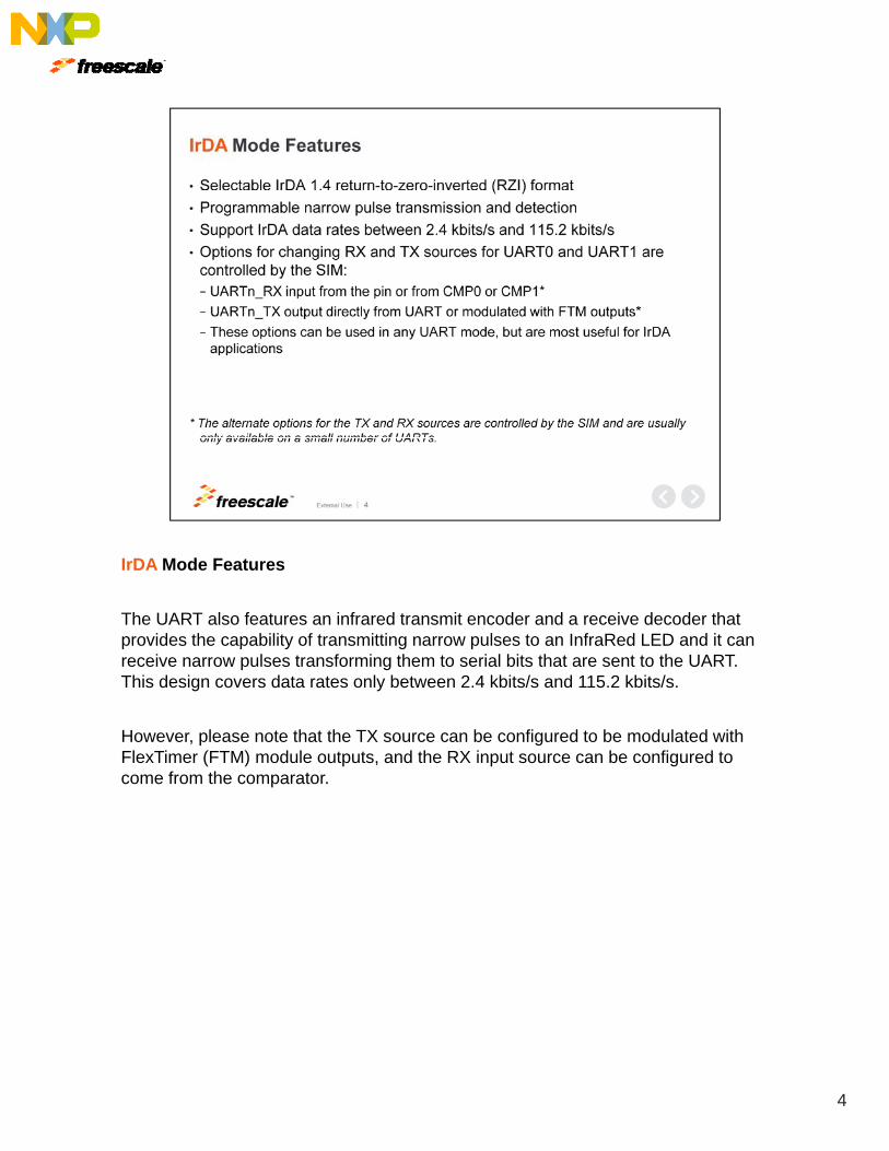
IrDA Mode Features
The UART also features an infrared transmit encoder and a receive decoder that provides the capability of transmitting narrow pulses to an InfraRed LED and it can receive narrow pulses transforming them to serial bits that are sent to the UART. This design covers data rates only between 2.4 kbits/s and 115.2 kbits/s.
However, please note that the TX source can be configured to be modulated with FlexTimer (FTM) module outputs, and the RX input source can be configured to come from the comparator.
4

ISO-7816 Mode Features
The UART provides mechanisms to support the ISO-7816 protocol that is commonly used to interface with smartcards.
There are multiple sub-protocols within the ISO-7816 standard. The UART supports both T = 0 and T = 1 protocols The module also supports automated initialboth T = 0 and T = 1 protocols. The module also supports automated initial character detection and 11 or 12 ETU transfers. It can also provide automated NACK responses and has programmed automated retransmission of failed packets.
Also, a list of interrupts specific to ISO-7816 are provided on the slide in addition to the general interrupts to assist software.
5
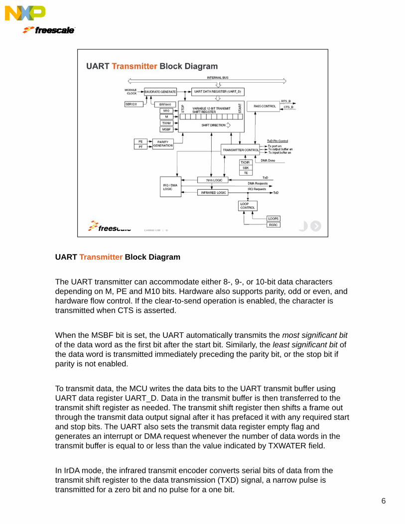
UART Transmitter Block Diagram
The UART transmitter can accommodate either 8-, 9-, or 10-bit data characters depending on M, PE and M10 bits. Hardware also supports parity, odd or even, and hardware flow control. If the clear-to-send operation is enabled, the character is transmitted when CTS is asserted.
When the MSBF bit is set, the UART automatically transmits the most significant bitof the data word as the first bit after the start bit. Similarly, the least significant bit of the data word is transmitted immediately preceding the parity bit, or the stop bit if parity is not enabled.
To transmit data the MCU rites the data bits to the UART transmit b ffer singTo transmit data, the MCU writes the data bits to the UART transmit buffer using UART data register UART_D. Data in the transmit buffer is then transferred to the transmit shift register as needed. The transmit shift register then shifts a frame out through the transmit data output signal after it has prefaced it with any required start and stop bits. The UART also sets the transmit data register empty flag and generates an interrupt or DMA request whenever the number of data words in the transmit buffer is equal to or less than the value indicated by TXWATER field.q y
In IrDA mode, the infrared transmit encoder converts serial bits of data from the transmit shift register to the data transmission (TXD) signal, a narrow pulse is transmitted for a zero bit and no pulse for a one bit.
6
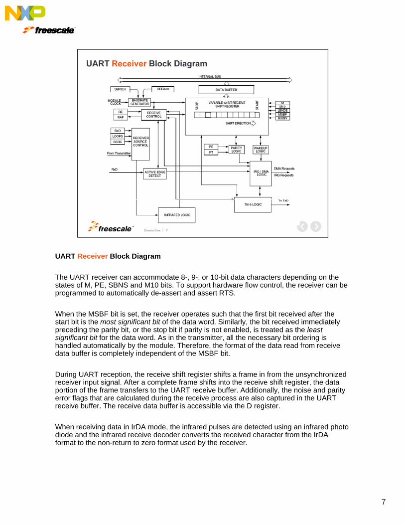
UART Receiver Block Diagram
The UART receiver can accommodate 8-, 9-, or 10-bit data characters depending on the states of M, PE, SBNS and M10 bits. To support hardware flow control, the receiver can be programmed to automatically de-assert and assert RTS.
When the MSBF bit is set, the receiver operates such that the first bit received after the start bit is the most significant bit of the data word. Similarly, the bit received immediately g y, ypreceding the parity bit, or the stop bit if parity is not enabled, is treated as the least significant bit for the data word. As in the transmitter, all the necessary bit ordering is handled automatically by the module. Therefore, the format of the data read from receive data buffer is completely independent of the MSBF bit.
During UART reception, the receive shift register shifts a frame in from the unsynchronized receiver input signal. After a complete frame shifts into the receive shift register, the data
ti f th f t f t th UART i b ff Additi ll th i d itportion of the frame transfers to the UART receive buffer. Additionally, the noise and parity error flags that are calculated during the receive process are also captured in the UART receive buffer. The receive data buffer is accessible via the D register.
When receiving data in IrDA mode, the infrared pulses are detected using an infrared photo diode and the infrared receive decoder converts the received character from the IrDA format to the non-return to zero format used by the receiver.
7
Now let’s discuss on-chip interconnection and inter-module dependencies.
8
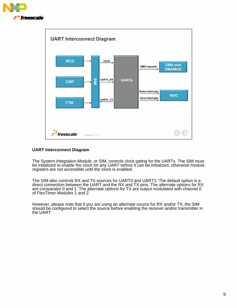
UART Interconnect Diagram
The System Integration Module, or SIM, controls clock gating for the UARTs. The SIM must be initialized to enable the clock for any UART before it can be initialized, otherwise module registers are not accessible until the clock is enabled.
The SIM also controls RX and TX sources for UART0 and UART1. The default option is a direct connection between the UART and the RX and TX pins. The alternate options for RX are comparator 0 and 1. The alternate options for TX are output modulated with channel 0 p p pof FlexTimer Modules 1 and 2.
However, please note that if you are using an alternate source for RX and/or TX, the SIM should be configured to select the source before enabling the receiver and/or transmitter in the UART
9
Next, lets talk about hardware configuration.
10

UART RS-232 Hardware Connections
This is a block diagram of the hardware connections for RS-232 implementation. The diagram shows the optional hardware flow control signals, but only the RX and TX data connections are required.
11

UART RS-485 Hardware Connections
This is a block diagram of the hardware connections for RS-485 implementation. Here RTS should be configured for TXRTS mode and active high polarity.
12
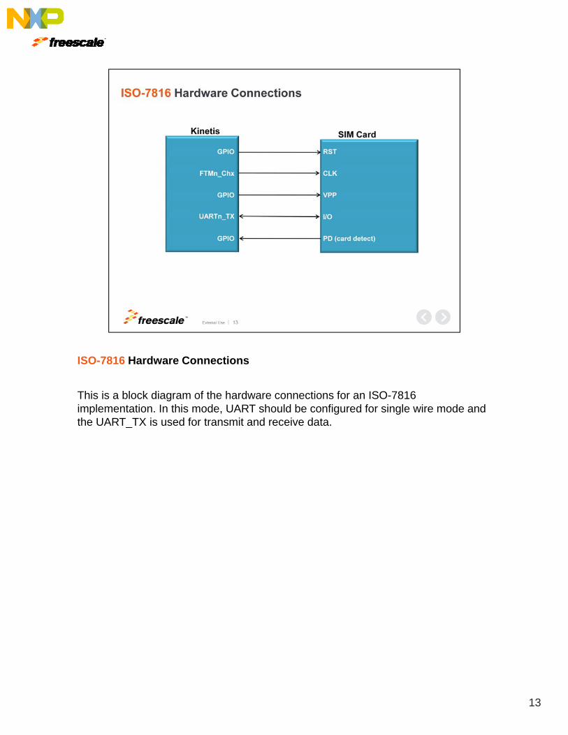
ISO-7816 Hardware Connections
This is a block diagram of the hardware connections for an ISO-7816 implementation. In this mode, UART should be configured for single wire mode andthe UART_TX is used for transmit and receive data.
13
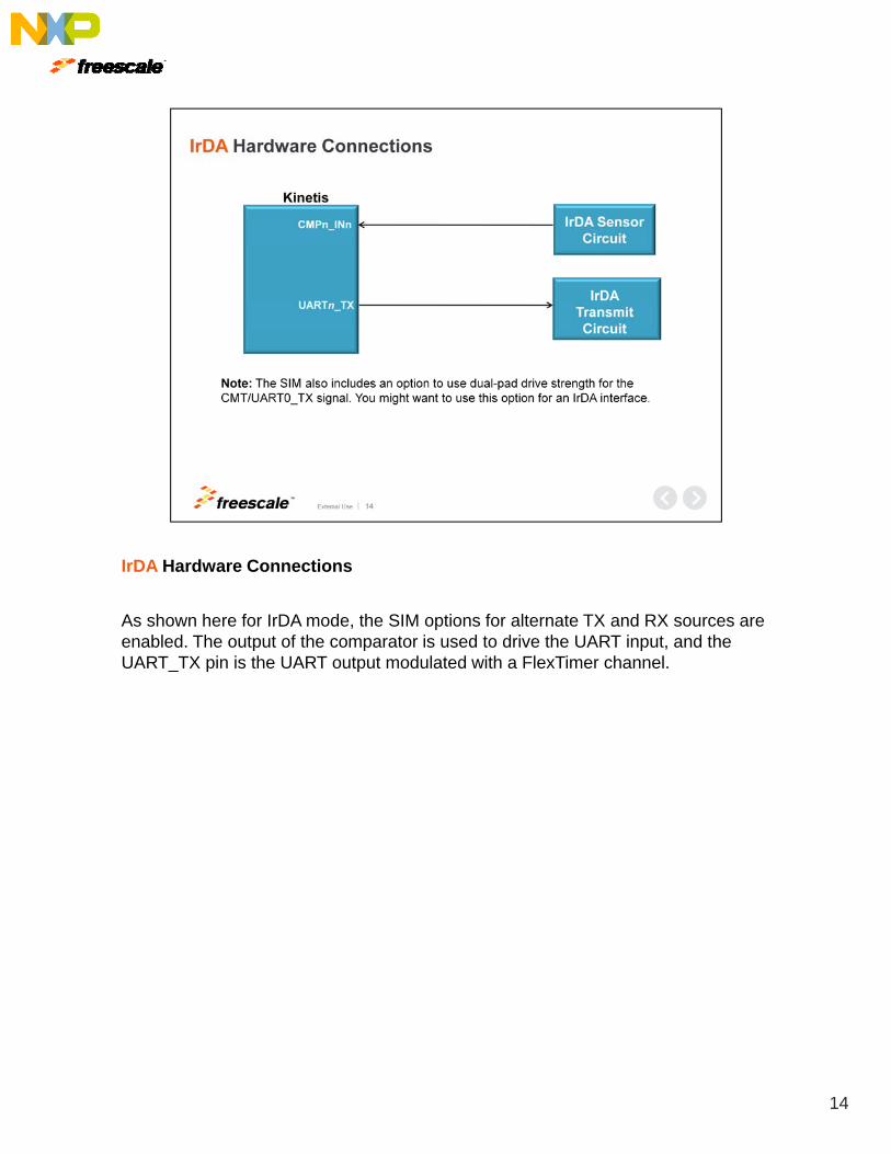
IrDA Hardware Connections
As shown here for IrDA mode, the SIM options for alternate TX and RX sources are enabled. The output of the comparator is used to drive the UART input, and the UART_TX pin is the UART output modulated with a FlexTimer channel.
14

Let’s now discuss software configuration.
15
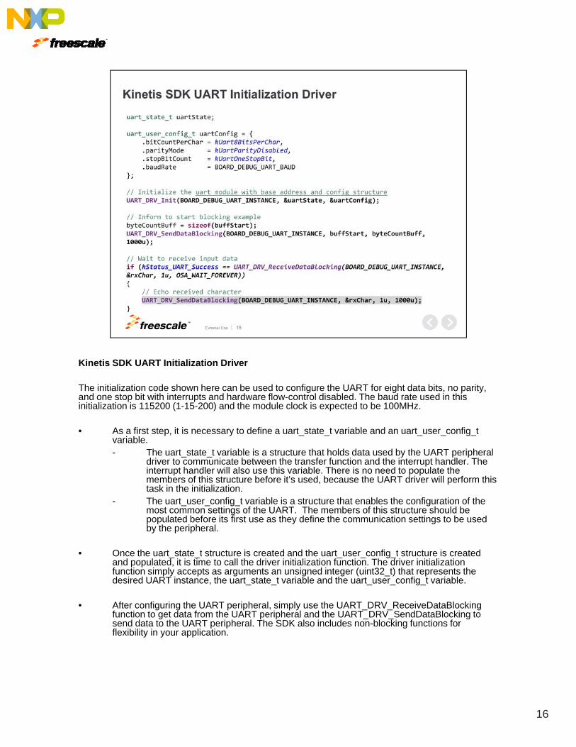
Kinetis SDK UART Initialization Driver
The initialization code shown here can be used to configure the UART for eight data bits, no parity, and one stop bit with interrupts and hardware flow-control disabled. The baud rate used in this initialization is 115200 (1-15-200) and the module clock is expected to be 100MHz.
• As a first step, it is necessary to define a uart_state_t variable and an uart_user_config_tvariable.- The uart_state_t variable is a structure that holds data used by the UART peripheral
driver to communicate between the transfer function and the interrupt handler Thedriver to communicate between the transfer function and the interrupt handler. The interrupt handler will also use this variable. There is no need to populate the members of this structure before it’s used, because the UART driver will perform this task in the initialization.
- The uart_user_config_t variable is a structure that enables the configuration of the most common settings of the UART. The members of this structure should be populated before its first use as they define the communication settings to be used by the peripheral.
Once the uart state t structure is created and the uart user config t structure is created• Once the uart_state_t structure is created and the uart_user_config_t structure is created and populated, it is time to call the driver initialization function. The driver initialization function simply accepts as arguments an unsigned integer (uint32_t) that represents the desired UART instance, the uart_state_t variable and the uart_user_config_t variable.
• After configuring the UART peripheral, simply use the UART_DRV_ReceiveDataBlockingfunction to get data from the UART peripheral and the UART_DRV_SendDataBlocking to send data to the UART peripheral. The SDK also includes non-blocking functions for flexibility in your application.
16
Finally, some frequently asked questions.
17

UART FAQs
Question: What is the UART max baud rate?
Answer: The max baud rate varies by device, but can be calculated using the following formula.
UART Max Baud Rate = (UART Module Clock Frequency) / 16
18

This concludes our presentation on the UART module for Kinetis MCUs.
For more UART module references, please access tthe User’s Guides listed here.
We also invite you to visit us on the web at Freescale.com/Kinetis and check out our Kinetis community page.
19

20