Embed Size (px)
Citation preview

NASA Technical Memorandum 101039
Helicopter Flights with Night-Vision Goggles- HumanFactors Aspects
Michael S. Brickner, Ames Research Center, Moffett Field, California
March 1989
I_lhSANaUonal Aeronautics andSpace AdrninistratJon
Ames Research CenterMoffett Reid, Califomia 94035
https://ntrs.nasa.gov/search.jsp?R=19890012106 2020-04-26T08:39:53+00:00Z

TABLE OF CONTENTS
Page
SUMMARY• ° "" " ° " • • "° • • "° ,.o • oo., .. _° o° * ,* oooo .° ° • *o • o°o • .* .*. • °°., *,°oo • • .4 • .o • °.** .* • °_ • • *o° *l ** o** i* • Io • • ** **o •, 1
I. INTRODUCTION 1o'''o**.o, ooo*o°*ooo**-*..*oo,********o****,..I.,**,,o.ooo..4o .eo,,.,.oo.o._,._.oo.,.,,o. o
II. NIGHT-VISION-GOGGLES SYSTEM CHARACTERISTICS .................................... 3
A. Technical Description ................................................................................... 3B. Night-Vision-Goggles Installation .................................................................... 4
C. Light-Intensifier-Tube Parameters .................................................................... 5
D. Cockpit Lighting ........................................................................................ 7
E. Superimposed Symbology ............................................................................. 8
III. DAY VISION AND NIGHT VISION .................................................................. 9
A. The Human Eye ........................................................................................ 10
B. Seeing by Day and by Night ........................................................................ 11
C. The Use of Night Vision Goggles ................................................................. 12
D. Night Myopia and Instrument Myopia ............................................................. 12
IV. SEEING THROUGH NIGHT VISION GOGGLESo°°o*****o° °6°****o°.,***°o°°** ,°o°o°,°°°°**.o°, 13
A. Field of View ........................................................................................... 13
B. Binocular Vision ........................................................................................ 13C. Focal Distance ........................................................................................... 14
D. Vision and Perception ................................................................................. 15
E. Slope Estimation ........................................................................................ 16
F. Instability of the World Image ...................................................................... 17
G. Brightness and Dazzling ............................................................................... 18
H. Monochrome Images ................................................................................... 18
I. Symboloby in NVGs .................................................................................. 18
J. Visual Fatigue ........................................................................................... 20K. Individual Differences .................................................................................. 21
V° LIGHT INTENSIFIERS VERSUS THERMAL IMAGINGA.
B.C.
D.
E.
........................................ 22
Thermal Imaging Systems ............................................................................ 22
Characteristics of the Thermal Image ............................................................... 23
FLIR Helicopter Flying ............................................................................... 24Comparison of Thermal Imaging and Light Intensifiers ........................................ 25
Combining NVGs and FLIR ......................................................................... 28
VI. CONCLUSIONS* °°°'**°°°****'°°°****°°°°°* °°°°°*_*'°°°*°*°° ° °°**'°°'°'**°o****.oo I,°*o°°°° .6.oo°**.*°°o_.. 30
REFERENCES°°" °*'°Q "° ° °*'° "°''* "t °°°°*'°°°'*4"°°°°**" °" °°*°'°°''°°*'°°°°**°°°°o,°oo°o°°,°*o-o*o°°°°° ,*,o°°oo**, • 31
PRECEDING PAGE BLANK NOT FILMED
°°°
111


HELICOPTER FLIGHTS WITH NIGHT-VISION GOGGLESBHUMAN FACTORS ASPECTS
Michael S. Brickner*
Ames Research Center
SUMMARY
Night-vision goggles (NVGs) and, in particular, the advanced, helmet-mounted Aviators Night-
Vision-Imaging System (ANVIS) allows helicopter pilots to perform low-level flight at night. It consists
of light intensifier tubes which amplify low-intensity ambient illumination (star and moon light) and anoptical system which together produce a bright image of the scene. However, these NVGs do not turn
night into day, and, while they may often provide significant advantages over unaided night flight, they
may also result in visual fatigue, high workload, and safety hazards. These problems reflect both systemlimitations and human-factors issues. A brief description of the technical characteristics of NVGs and of
human night-vision capabilities is followed by a description and analysis of specific perceptual problems
which occur with the use of NVGs in flight. Some of the issues addressed include: (1) limitations
imposed by a restricted field of view; (2) problems related to binocular rivalry; (3) the consequences of
inappropriate focusing of the eye; (4) the effects of ambient illumination levels and of various types of ter-
rain on image quality; (5) difficulties in distance and slope estimation; (6) effects of dazzling; and (7) visual
fatigue and superimposed symbology. These issues axe described and analyzed in terms of their possible
consequences on helicopter pilot performance. The additional influence of individual differences amongpilots is emphasized. In the last section thermal imaging systems (forward looking infrared (FLIR)) are
described briefly and compared to light intensifier systems (NVGs). Many of the phenomena which are
described in the present report are not readily understood. More research is required to better understand
the human-factors problems created by the use of NVGs and other night-vision aids, to enhance systemdesign, and to improve training methods and simulation techniques.
I. INTRODUCTION
Pilots of helicopters and other types of military aircraft rely heavily on visual information for naviga-
tion, obstacle avoidance, and target detection and acquisition. Hence, the ability to perform missions dur-ing the night (or other periods of reduced visibility) is severely restricted in comparison with operations in
good visibility. Considering the tactical importance of night operations, considerable effort has been
invested in the design and development of various visual aids. Some of the most important systems are:
1. Visible light sources- Search lights were used widely during World War II, particularly indefense missions, to aid in the detection of aircraft and other types of targets and are still used under some
circumstances. Flares axe widely used to illuminate wide areas for a limited period of time; a series of
flares can be used to provide successive illuminations of an area. The use of flares may eliminate the
*National Research Council Research Associate.

chancesof surprising the enemy, however, as they reveal both friends and foes, and destroy night-visionadaptation for a long period of time.
2. Invisible light sources- Sources of invisible electromagnetic radiation such as infrared radiation in
the range of 0.7-1.2 grn, may be used by operators who are equipped with appropriate devices. These
consist of a filter which is installed on a fight projector and allows only invisible infrared fight to comethrough. Visual aids which are responsive at these particular wavelengths enable the user to see the illu-
minated area. The quality of visual information thus provided is generally inferior to visible light source
in both intensity and range of illumination. In addition, the fight may be detected by anyone who pos-sesses proper viewing devices.
3. Thermal imaong- Forward Looking Infrared (FLIR) systems consist of detectors which are
reactive to radiated heat (radiation in the far infrared, 3-5 or 8-14 grn), optical components, and signalprocessors which transform the signal into a visible display. The FLIR systems are in wide use for
surveillance purposes, target detection and acquisition, helicopter flying, etc. Considerable effort has been
invested in several countries to improve these systems and to increase the scope of their applicability.
Some of the advantages of thermal-imaging systems are:
a. A world view can be obtained independent of visible fight sources.
b. Targets can be detected through smoke, dust, and camouflage.
c. Hot targets may be detected from long distances.
Some of the disadvantages are:
a. Technical complexity, heavy weight, large size, and high cost.
b. The thermal image is significantly different from black and white video images, and thus, may bedifficult to interpret.
c. The image changes over time and its quality depends on weather and atmospheric conditions.
4. Light intensificatiQn- Light-intensifying systems are based on tubes which intensify fight in thevisual and the near infrared band (0.35-0.95 lain). Such systems are capable of creating a bright "window"
in an otherwise dark environment. To do so, they depend on the existence of sufficient light in the scene.The signals received by a light-sensitive substance may be wansfonned into a video signal to create a"low-fight-level television" or projected directly onto a miniature phosphor screen. The latter solution is
implemented in night-vision goggles (NVGs). In recent years, NVGs underwent important technical
improvements and gained an increasingly important role in the performance of night missions by rotary-wing and fixed-wing aircraft.
The use of NVGs in flight for helicopter and other aircraft flying, raises a series of human-factors
questions regarding night vision, perceptual phenomena, safety, and training. This paper deals with the
human-factors aspects of helicopter flight using NVGs. There is particular emphasis on the visual and
perceptual encounters of skilled and novice operators. This report is partially based on a recent report on
NVGs in helicopter operations performed by the Israel Air Force, which was written by the author in
collaboration with Michael Wagner and Daniel Gopher (Brickner, Wagner, and Gopher, 1987).
2

II. NIGHT-VISION-GOGGLES SYSTEM CHARACTERISTICS
A. Technical Description
Thebasicstructureof NVGs is quite simple.
1. A field lens (objective) concentrates incoming light rays onto an image intensifier tube (fig. 1).
2. The image intensifier tube consists of a photo cathode,--a photo-sensitive substance that emits
electrons when exposed to light in the visible or the near infrared band, and an electron multiplier (or
microchannel plate), which multiplies the electrons thousands of times. By varying the voltage across theelectron multiplier disc, the gain of the multiplier can be controlled.
MICROCHANNEL
PLATE
CA TH (__PHOTO PHOSPHORL,OHT\%-" k J
/ INDIVIDUAL "" ,_.INPUT I MULTIPLIER CHANNEL "" "_
SECONDARY
ELECTRONS
Figure 1.- Diagram of an intensifier tube.
Second- and third-generation tubes have an automatic gain control (AGC) system which controls the
level of electron multiplying and protects it from excessive firing. The signals from the electron multiplier
are transmitted through a bundle of fiber optics to a phosphor screen on which a visible image is created.
The type of phosphor used determines the color of the image (usually green) and its persistence.
3. The collimating lens projects the image to optical infinity and focuses it onto the users' eyes.Alternatively, an indirect optical path may be devised, such that the image is viewed on a combining lensrather than directly from the phosphor screen.
4. Electrical power is supplied by batteries which are an integral part of the goggle housing in somesystems and a separate box in others.
3
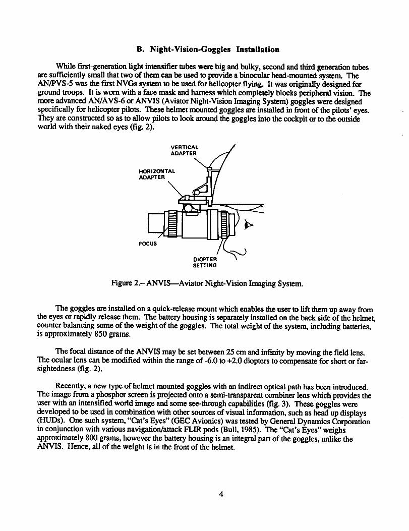
B. Night-Vision-Goggles Installation
While first-generation light intensifier tubes were big and bulky, second and third generation tubes
are sufficiently small that two of them can be used to provide a binocular head-mounted system. The
AN/PVS-5 was the first NVGs system to be used for helicopter flying. It was originally designed for
ground troops. It is worn with a face mask and harness which completely blocks peripheral vision. The
advanced AN/AVS-6 or ANVIS (Aviator Night-Vision Imaging System) goggles were designed
specifically for helicopter pilots. These helmet mounted goggles axe installed in front of the pilots' eyes.They are consu'ucted so as to allow pilots to look around the goggles into the cockpit or to the outsideworld with their naked eyes (fig. 2).
VERTICAL
HORIZONTAALDAPTER_
ADAPTER I_ _
FOC_
SETTING
Figure 2.-ANVIS---Aviator Night-Vision Imaging System.
The goggles are installed on a quick-release mount which enables the user to lift them up away fromthe eyes or rapidly release them. The battery housing is separately installed on the back side of the helmet,
counter balancing some of the weight of the goggles. The total weight of the system, including batteries,is approximately 850 grams.
The focal distance of the ANVIS may be set between 25 cm and infinity by moving the field lens.The ocular lens can be modified within the range of-6.0 to +2.0 diopters to compensate for short or far-sightedness (fig. 2).
Recently, a new type of helmet mounted goggles with an indirect optical path has been introduced.
The image from a phosphor screen is projected onto a semi-transparent combiner lens which provides the
user with an intensified world image and some see-through capabilities (fig. 3). These goggles were
developed to be used in combination with other sources of visual information, such as head up displays(HUDs). One such system, "Cat's Eyes" (GEC Avionics) was tested by General Dynamics Corporation
in conjunction with various navigation/attack FUR pods (Bull, 1985). The "Cat's Eyes" weighs
approximately 800 grams, however the battery housing is an integral part of the goggles, unlike the
ANVIS. Hence, all of the weight is in the front of the helmet.
4

OBJECTIVE I IT
COMBINING EYE PIECE
Figure 3.- Diagram of"Cat's Eyes" NVGs with see-through capabilities.
C. Light-Intensifier-Tube Parameters
In this paper some of the parameters which are most relevant to operators' performance are dis-
cussed. A detailed technical description of the hardware can be found in Verona (1985). The data is based
on Litton's second-generation L-4261 tubes and on Varian VLIA-238 third-generation tubes. Specificfeatures may be somewhat different in other brands.
1. Resolution- The resolving power of the goggles depends on the combined characteristics of all its
components and is related to the contrast level of the scene. Maximal resolution is 25 pixelsdmm at thecenter of the screen. Hence, the total maximum resolution of the round screen is approximately 450 pixels
along its diameter. With 30% contrast, NVGs resolution drops to 16 pixels/mm or approximately 290 pix-
els along the diameter of the screen. Third-generation tubes may have up to 36 line-pairs/ram or a maxi-
mum resolution of 648 pixels along the diameter. In addition, they are more effective in low-brightnessand low-contrast conditions.
Visual information thus provided may enable NVG users to estimate the probability of detecting or
recognizing various targets. For example, let us assume that the width of a telephone pole is 30 era.
According to Johnson's criteria (Johnson, 1958), 2 pixels are required to detect a target. However, due tothe length of the target one may assume that 1 pixel may suffice. Given that the total field of view is 40 °
and there are approximately 650 pixels across the screen, one pixel extends 0.06 ° or 0.001 rad. The tele-
phone pole will extend 0.001 mrad of visual angle from a distance of 300 m
Distance = 0.30 m/0.001 rad = 300 m
Thus, with the aid of an image intensifier, under optimal viewing conditions, a telephone pole may
be detected from a distance of approximately 300 m.
In comparison, given sufficient contrast, the unaided eye has a resolving power of approximately
1 min of arc or 0.0003 rad (Snyder and Miller, 1977). Thus, under good day time visibility, the same
telephone pole may be detected from a distance of approximately 1000 m
Distance = 0.30 m/0.0003 rad = 1000 m
In other words, the detection of small targets is limited by the resolution of the NVGs and is three to
four times less than the maximum resolving power of the unaided eye during day time conditions.
2. ]lI]_llll_- NVGs images are similar to those provided by a monochrome television screen.
Image quality depends on the characteristics of the light intensifier tube, the optical system, atmosphericconditions, the nature of the scene, and ambient lighting. The maximum visual acuity of NVGs is often
described in terms of visual acuity, and is supposedly 20/50 for second-generation and 20/40 for third-
generation tubes (Tucker, 1984; Genco, 1985; Department of the Army, Field Manual 1983). This implies
that a NVGs user should be capable of identifying from a distance of 20 ft, an object which a normal eye
would identify from a distance of 40 ft. This acuity measure is ambiguous however, because as shown
above, the resolving power of the unaided eye under good visibility, is three to four times higher than theresolution provided by third-generation NVGs. Thus the ability of NVGs to resolve fine detail is in factsmaller than 20/40.
3. Ambient fighting- The tube amplifies the light which is reflected from objects in the scene. On a
bright night, the image will be bright and will consist of a wide range of gray shades. On a dark night the
image will be darker and the range of gray shades reduced. Image brightness cannot be controlled by the
user. Peak display luminance of second-generation NVGs is 0.3-0.7 foot lamberts (FL) and of third-generation NVGs 0.7-2.2 FL (Verona, 1985). The relatively low brightness level of the NVG display
severely limits the number of distinct gray shades which can be displayed. Thus, brightness variability in
the scene has to be mapped into a rather limited range of brightness in the display. The higher brightness
and the improved range of third-generation tubes is one of its most important advantages over second-generation tubes.
4. Atmospheric conditions- Elecmamagnetic radiation within the sensitivity range of the tube
(predominantly red and near infrared) is adversely effected by some of the factors to which the human eye
is also sensitive, e.g., dust, moisture and haze. Thus, NVGs may not be of much help in fog or haze andmay not provide the required visual information during hovering or landing in dust or snow.
5. Automatic gain control tAGC)-- The AGC adapts the brightness of the screen to changes in ambi-
ent illumination levels and to protect the electron multiplier from extensive firing when exposed to stronglight. In fin'st- and second-generation NVGs, bright light sources such as car headlights or flaxes, create a
halo or "blooming" around the bright light and degraded the contrast of adjacent portions of the image. Inthird-generation tubes, AGC balances the brightness level of the whole image, more effectively. How-
ever, this also results in a darker image with lower contrast ratios (Verona, 1985). Thus, the presence of
even a small source of bright light in the field of view of the NVGs reduces the average brightness of the
image and its ability to produce distinct contrasts.
6. Noise- The photo cathode randomly emits electrons, which create a constant noise level. When
the world image is bright, signal-to-noise ratio is high and noise has little effect on the visual image.When the image is dark, however, the signal-to-noise ratio is lower so the image may be significantly
degraded by the noise.
7. Tube ¢¢nditign- Light intensifiers have a limited life span. Their performance gradually deterio-
rates as a function of time and light exposure. Since the tubes may be replaced independently, one may be
significantly inferior to the other at any point in time. The differences in brightness between the twoimages may cause depth and movement illusions such as the Pulfrich pendulum (Rogers and Anstis,
1972). Another possible outcome is that the weaker image may be suppressed, resulting in a monocular
rather than a binocular image. Hence, it is very important to avoid this situation by maintaining both tubes
at adequate and approximately equal levels of performance.
6

8. Goggle's mechanical condition- The goggles must be in good mechanical condition. Shaking
controls or worn-out joints may cause various optical problems. One common (and usually ignored)
defect occurs when the two tubes are not exactly parallel. This may lead to the suppression of the image ofone eye, inappropriate distance estimation, and headaches (see also section IV.B-IV.D).
9. _- A scratched or dirty windshield may significantly reduce night visibility withunaided eyes. The effect may be even more pronounced with NVGs, because of to their enormous sensi-
tivity to the light which may be reflected by the scratches or by dust particles (see also next section).
D. Cockpit Lighting
The image intensifier multiplies the light that reaches the tube thousands of times. The rate of light
intensification depends on its wavelength. Second-generation tubes are reactive to light in the range of0.35-0.90 gm, with a sensitivity peak around 0.50 I.tm (fig. 4). Third-generation tubes react in the rangeof 0.50-0.92 _tm, with a peak around 0.85 _tm.
t I_110I<_ FILTER _ / / _]l, I I
.-'1 1'°':tl
'°t "xl t°''z.3 .5 .7 .9
WAVELENGTH, micrometers
Figure 4.- Wavelength sensitivity of second- and third-generation NVG tubes and the effect of"minusblue" filter.
Most military helicopter crew stations are equipped with red light, which is especially designed to
preserve night-vision adaptation ("aviation red"---0.6 I_m and above). However, this light also interferes
with the NVGs. It causes an automatic gain reduction which results in a poor world image (Breitmaier and
Reetz, 1985). Secondary reflections from the windshield which are in the user's direct field of view, may
be even worse than the original light sources. Broad-band white light, used in fighter aircraft cockpits,creates similar effects.
The problem may be solved by using short wavelength light. Both generations of tubes are relativelyinsensitive to blue light in the range below 0.38 lain. However, blue light is ineffective for instrument and
7

map reading. Hence, a compromise has to be made: using a blue-green or green light which satisfies boththe requirements of the pilots' eyes and the NVGs.
The problem is easier to solve with third-generation tubes which have a clear cutoff point below0.50 gin. In the third-generation ANVIS, a "minus blue" filter, which rejects wavelengths under
0.665 gm is built in (fig. 4). It enables the use of a relatively wide range of blue and green lighting in the
cockpit (Verona, 1985). While this filter has little effect on image quality in vegetated areas, it may signif-icantly reduce the contrast levels of desert views. Thus, for desert environments, a lower cutoff point of0.625 grn is recommended.
The use of homogenous, narrow band, green lighting raises a series of human factor problems:
a. It is difficult to distinguish colors or even gray shades on maps and aerial photographs.
b° The use of color coding, such as red warning lights, causes serious problems. With the intro-
duction of multi-purpose CRTs into helicopter cockpits, particularly color displays, the problemmay become even more complicated (Genco, 1985).
C, The sensitivity of the retinal rod system at 0.5 gm (green ligh0 is approximately 5 orders ofmagnitude higher than at 0.68 l.tm (red light) (Hood and Finkelstein, 1986, pp. 5.9-5.12).
Hence, green light has a stronger detrimental effect on night-vision adaptation than does red
light. As long as the pilot uses his NVGs his eyes are not dark adapted and he does not rely on
unaided vision. However, aircrew members who do not use goggles, may be effected by the
green light and experience deteriorated dark adaptation.
This raises a basic dilemma about the design of future crew station lighting systems. Should eachcockpit have dual systems of red and green lighting (resulting in considerable technical problems), or is it
sufficient to have only NVG-compatible lighting? Will NVGs prevent the use of multicolor display sys-tems in the future cockpit (or require them to have a monochrome backup mode)? More research is
.req.'.tared.to determine the operational consequences of reduced dark adaptation due to green light, and thelmplicauons of NVG lighting compatibility on the design of advanced crew stations.
E. Superimposed Symbology
Although the ANVIS is designed to enable the user to see the instrument panel with his naked eyes,
reading instruments which are different in illumination and optical distance from the world view, is quite
difficult (Simmons, Kimball and Hamilton, 1985). When flying at very low altitudes or while hovering in
dust or fog, pilots are practically incapable of monitoring flight instruments. Therefore, they must rely
heavily on information about aircraft status provided verbally by the copilot. This requires a high level ofcooperation and coordination by the flight crew (Haidn, 1985).
Recently, attempts have been made to add flight symbology to NVGs (e.g., Simmons, Kimball, and
Hamilton, 1985). Since the intensifier tube does not have video input capabilities, symbology has to be
incorporated into the optical path, in front of or behind the tube. One technical solution is to project animage from a miniature CRT onto a semitransparent combiner lens which is installed in front of one of the
tubes. Symbology is seen through the NVGs, superimposed on the world view (fig. 5).
8

; oulcKRELEASE\ CLAMPMOUNTFOR
! _ \._ /_'_'_\ OPTICAL COMBINER
"w',, Y.,--,
t FIBER-OPTIC _ rL_O'_\.///.BUNDLE '_ _._ _
DISPLAY A OPTICS
Figure 5.- Side view of NVG symbol generator in active position (solid line) and stowed away (dottedline).
This solution seems to be more feasible than the attempts to display the symbology after the NVGs
(between the eyes and the goggles; Simmons, Kimball, and Hamilton, 1985), because it displays the
symbology and the world view through the same optical system. It raises however some technical andhuman factors problems:
a. The color of the CRT has to be chosen such that it may be seen through the goggles but does notinterfere with the world image.
b. The display has to be bright enough to be legible against various backgrounds. However, the
automatic gain control (AGC) does not distinguish between symbology and other sources of
light. Therefore, it may adapt the tube to the bright symbols by reducing its sensitivity, resultingin a dark and reduced quality world view.
c. Further perceptual implications of flight symbology are discussed in section IV.G.
III. DAY VISION AND NIGHT VISION
The human visual system is the most important source of information during flight. Pilots rely on
acute vision to detect remote targets and small obstacles. Depth perception is required to estimate altitudeand distance. Peripheral vision enhances velocity estimation, obstacle detection and general orientation.
During the day, with good visibility, the pilots' eyes provide a clear and highly detailed image of the envi-
ronment. At night, the amount of available information is reduced in many different ways (e.g., bright-ness, contrast ratio, level of detail, color). The use of visual aids, such as NVGs, enhances information
for only some of these sources of reduced visibility, but at the expense of degrading other visual func-
tions. Some basic understanding of human day and night vision may be of value for the operator who hasto rely on night vision, with or without visual aids.
9
A. The Human Eye
The human eye may be compared to a camera containing optical components (lenses) and a light-sensitive screen ("film"). This is a highly sophisticated system which contains two complementary sub-
sysmms (the two eyes) and is capable of adjusting to day and night operation across a range of almost
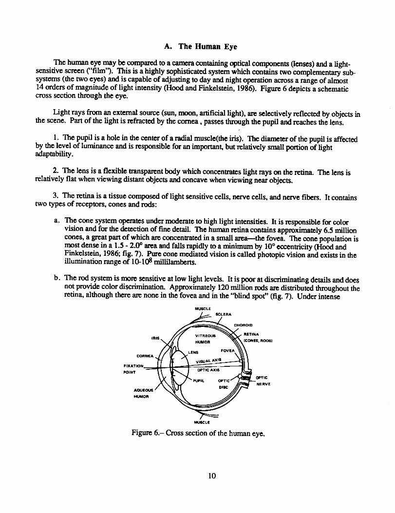
14 orders of magnitude of light intensity (Hood and Finkelstein, 1986). Figure 6 depicts a schematiccross section through the eye.
Light rays from an external source (sun, moon, artificial light), are selectively reflected by objects inthe scene. Part of the light is refracted by the cornea, passes through the pupil and reaches the lens.
1. The pupil is a hole in the center of a radial muscle(the iris). The diameter of the pupil is affectedby the level of luminance and is responsible for an important, but relatively small portion of lightadaptability.
2. The lens is a flexible transparent body which concentrates light rays on the retina. The lens is
relatively flat when viewing distant objects and concave when viewing near objects.
3. The retina is a tissue composed of light sensitive cells, nerve cells, and nerve fibers. It containstwo types of receptors, cones and rods:
a. The cone system operates under moderate to high light intensities. It is responsible for colorvision and for the detection of fine detail. The human retina contains approximately 6.5 million
cones, a great part of which are concentrated in a small area--the fovea. The cone population is
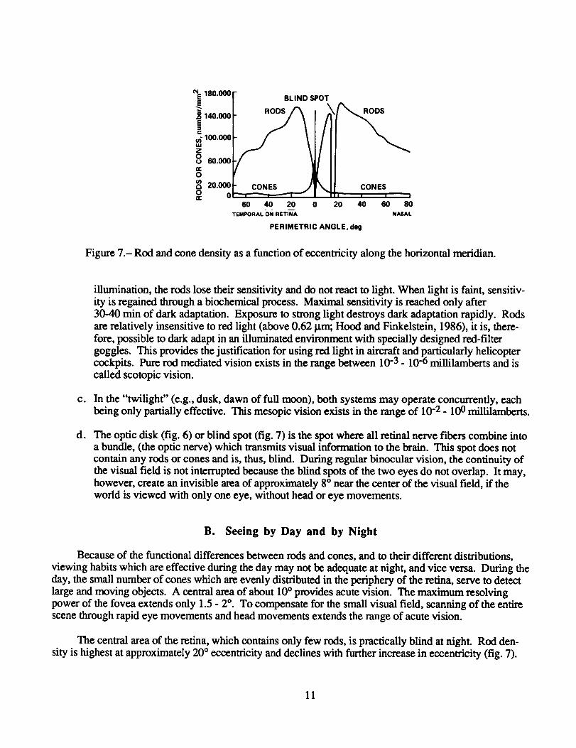
most dense in a 1.5 - 2.0 ° area and falls rapidly to a minimum by 10 ° eccentricity (Hood andFinkelstein, 1986; fig. 7). Pure cone mediated vision is called photopic vision and exists in theillumination range of 10-108 millilamberts.
b. The rod system is more sensitive at low light levels. It is poor at discriminating details and does
not provide color discrimination. Approximately 120 million rods are distributed throughout theretina, although there are none in the fovea and in the "blind spot" (fig. 7). Under intense
MUSCLE
SCLERA
CHOROID
_ RETINA
IRIS $, RO(_)
F IXATION__.__._÷
POINT OPTIC
NERVE
HUMORAQUEOUS"
MUSCLE
Figure 6.- Cross section of the human eye.
10
NE 180.000E
._ 140.000EC
_ 11111.111111W
zoo 60.000n-o
8 20._ _o 0
60 40 20 0TEMPORAL-OI_I RETtN_A
BLIND SPOT
\ CONES
20 40 60 80N,M_AL
PERIMETRIC ANGLE, deg
Figure 7.- Rod and cone density as a function of eccentricity along the horizontal meridian.
C.
d°
illumination, the rods lose their sensitivity and do not react to light. When light is faint, sensitiv-
ity is regained through a biochemical process. Maximal sensitivity is reached only after
30-40 min of dark adaptation. Exposure to strong light destroys dark adaptation rapidly. Rods
are relatively insensitive to red light (above 0.62 _trn; Hood and Finkelstein, 1986), it is, there-
fore, possible to dark adapt in an illuminated environment with specially designed red-filter
goggles. This provides the justification for using red light in aircraft and particularly helicoptercockpits. Pure rod mediated vision exists in the range between 10 -3 - 10 -6 millilamberts and is
called scotopic vision.
In the "twilight" (e.g., dusk, dawn of full moon), both systems may operate concurrently, eachbeing only partially effective. This mesopic vision exists in the range of 10 -2 - 100 millilamberts.
The optic disk (fig. 6) or blind spot (fig. 7) is the spot where all retinal nerve fibers combine into
a bundle, (the optic nerve) which transmits visual information to the brain. This spot does not
contain any rods or cones and is, thus, blind. During regular binocular vision, the continuity ofthe visual field is not interrupted because the blind spots of the two eyes do not overlap. It may,
however, create an invisible area of approximately 8 ° near the center of the visual field, if theworld is viewed with only one eye, without head or eye movements.
B. Seeing by Day and by Night
Because of the functional differences between rods and cones, and to their different distributions,
viewing habits which are effective during the day may not be adequate at night, and vice versa. During theday, the small number of cones which are evenly distributed in the periphery of the retina, serve to detect
large and moving objects. A central area of about 10 ° provides acute vision. The maximum resolving
power of the fovea extends only 1.5 - 2 °. To compensate for the small visual field, scanning of the entirescene through rapid eye movements and head movements extends the range of acute vision.
The central area of the retina, which contains only few rods, is practically blind at night. Rod den-
sity is highest at approximately 20 ° eccentricity and declines with further increase in eccentricity (fig. 7).
11
Hence, effective night-vision has to rely on more peripheral zones of the retina. Staring, which is notrecommended during the day, is particularly detrimental for night-vision. Furthermore, rods which have
been exposed to light may be easily saturated and temporarily lose their sensitivity. Thus, it is necessary
for pilots to scan the scene such that different parts of the retina participate in the scanning process. Dur-
ing twilight, both visual systems may operate together (mesopic vision). At such times, staring may oftenoccur, in an effort to compensate for the low efficiency of foveal vision. However, pilots should avoid
this strategy, because it is important to take advantage of both foveal cone vision and peripheral rodvision, to scan the scene, and to avoid staring.
C. The Use of Night Vision Goggles
The brightness of the NVG display is in the range of 0.3-0.9 footlamberts (second-generation) or
0.7- 2.2 footlamberts (third-generation; Verona, 1975). Image brighmess depends on the level of ambient
lighting. In a bright scene, the image is relatively bright and when the scene is dark, the NVG image is
less bright. The whole range of NVG image brightness is in the medium or high mesopic region where
both day and night visual systems operate concurrently (Price and McLean, 1985). However, despite the
fact that the rod system is partially operating, the pilots' eyes axe not fully dark adapted, thus the efficiency
of peripheral vision to monitor the dark outside world, is reduced. The pilots' peripheral, see-aroundcapability (see section II.B and fig. 2) can be used to observe illuminated objects such as flight instruments
or maps. And, most important, pilots are capable of perceiving the contour lines of the cockpit and thewindshield, to preserve spatial orientation.
After taking the goggles off, approximately 2 min are required to regain full night adaptation (Price
and McLean, 1985). For a while, the world may seem "pinkish." This is a chromatic afterimage resultingfrom the long exposure to green light (the color of the phosphor).
D. Night Myopia and Instrument Myopia
Pilots are usually required to have at least 20/20 visual acuity, although corrected vision is acceptablein some cases. Surprisingly, national aviation regulations in most western countries (e.g., FAA, US Air
Force, German civil aviation, German Bundeswehr, Israel Air Force; Draeger, Hanke, and Wirt, 1985),
do not impose any standards for night-vision ability. However, a significant percentage of people withperfectly normal day vision, suffer from night myopia (Sloan, 1947). In general, night-vision standards
are not nearly as well-established as are day vision standards. Night-vision is much more difficult to
define and measure than day vision because it is highly dependent on the level of dark adaptation, illumi-
nation levels, and the presence of dazzling light sources. Some pilots are not aware that their night-visionis deficient or choose to ignore it. It has been found (Wagner and Davidson, 1987) that the use of
correcting glasses during night flights only, may minimize the problem of night myopia in some cases.
People who suffer from instrument myopia require optical correction when viewing through optical
instruments (I-Iennesy, 1975). It is quite common for a pilot with normal day vision to choose a negative
diopter setting (to compensate for short-sightedness) for their NVGs. This may have some negativeimplications:
a. Some pilots may not be aware of their night-vision or instrument-vision capabilities. The qualityof an NVG image depend on many variables, therefore, it may be difficult for a pilot to decide
whether the image he is watching is optimal.
12

b. The optical correction of myopia, particularly over correction and unbalanced correction of the
two eyes, may increase misperception of the size, distance, and slopes of objects in the visualscene. (see section IV.D).
C. Unlike the ANVIS, some NVGs, such as the cat's eyes, may not be equipped with built-in
diopter adaptation. Therefore, when using "cat's eyes," the pilots may have to use glasses or
contact lenses to correct their vision. However, pilots with normal day vision may not have
glasses and may be unaware of the advantages of optical correction at night.
IV. SEEING THROUGH NIGHT VISION GOGGLES
The NVGs provide pilots with a bright "window" in a dark environment which gives them an
important operational advantage and enhances flight safety. One should keep in mind, however, that
NVGs do not turn night into day. The world image provided by NVGs has many limitations in compari-son with normal daytime visibility. This section discuses some of the visual and perceptual characteristicsof NVGs.
A. Field of View
Despite the "see around" capability, provided by contemporary NVGs, pilots' effective field of viewis considerably reduced in comparison to unaided vision. The ANVIS has a round 40 ° field of view
(FOV), while the "cat's eyes" provides only a 30 ° field of view. Peripheral vision may provide importantcues from the illuminated cockpit environment, but outside peripheral vision is practically eliminated
because pilots' eyes are not dark adapted.
In visual flight, pilots depend on peripheral motion cues to estimate speed, altitude, obstacle clear-
ance, and orientation (e.g., Anstis, 1986). In addition, they make extensive use of eye movements to scan
the field of view. The natural response to a novel object in the peripheral field, or to an abrupt movementof an object, is a combined movement of both head and eyes toward the object (Hallett, 1986).
NVGs require different, and sometimes unnatural viewing habits. The elimination of peripheral
vision and the limited value of eye movements has to be compensated for by constant head movements.
Head movements have to be performed slowly and constantly from the center to each side. This ratherunnatural behavior has to be acquired during flight training and maintained through practice.
B. Binocular Vision
Most NVGs have two parallel optical paths with two light intensifiers. Each eye is provided with aslightly displaced image, creating binocular vision. In spite of this, pilots report that the world viewed
through NVGs appears to be "flatter" than a direct view (Brickner, Wagner, and Gopher, 1987;
Department of the Army, Field Manual, 1983). Severe problems may occur if, for some technical reason,the two optical axes are not parallel:
13

a.
b°
If the optical axes converge, the eyes may converge in the same direction, as though they wereviewing a near object (fig. 8a). As a result, under-estimation of size and distance may occur.
In contrast with convergence which is a natural mechanism for viewing near objects, horizontal
and vertical divergence are not required in normal vision (fig. 8b). Thus, the eyes have verylimited ability to compensate for divergence of the optical axes. As little as 1-2 milliradians of
divergence may cause visual fatigue, eye strain, headaches, and even double vision (Warren
et al., 1984). Some users may cope with this stressful situation by deliberately orunconsciously suppressing one of the images, thereby losing all binocular depth cues and muchof their contrast sensitivity.
A. CONVERGENCE
EREAL
PERCEIVED O_ECT
IMAGE
B. DIVERGENCE \PERCEIVED
IMAGEREAL
OBJECT /
E
Figure 8.- The effect of convergence and divergence of the optical axes. Convergence may result insize/distance underestimation, while divergence may lead to double vision.
C. Focal Distance
In the second-generation AN/PVS-5 NVGs, peripheral vision is totally occluded. In addition to the
problems createdby the lackof peripheralvision,thereisa problem of focaldistance.Whereas theworld
view requiresa distantfocus ("infinity"),instrument,map and chartreadingdemands a nearfocus. Some
of the technicalsolutionswhich have been suggestedare:
a. Manual adjustment of the distance of the field lens; requires pilots to re-adapt the goggles everytime they want to read an instrument.
b. Using bifocalfieldlenses.
c. Modifying theNVGs toprovide unaided look-underand look-to-the-sidecapabilities(PriceandMcLean, 1985).
14
The last solution is the only one that is effective and has gained pilot acceptance. In the more
advanced NVGs, such as the helmet-mounted ANVIS, optical distance is usually maintained at "inf'mity"to provide a clear view of the outside world. Instruments are read with unaided vision, by glancingbeneath the goggles. Shifting from an outside view to the instrument panel and vice versa is a time con-
suming process. It takes about 1 see to adapt the focal distance from infinity to a near point or vice versa
(Westheimer, 1986). Thus, the total time which is normally required during day flights, to glance into thecockpit, read an instrument, and return to the outside world, is approximately 3-5 seema substantial inter-
val of time during low-level flight. When this process has to be performed during NVG flight, it may takeeven longer because of the unnatural angle of gaze and to possible brightness differences between the
NVG image and the instrument panel.
D. Vision and Perception
Vision and perception through NVGs involve some unique phenomena, that result from the charac-
teristics of the system.
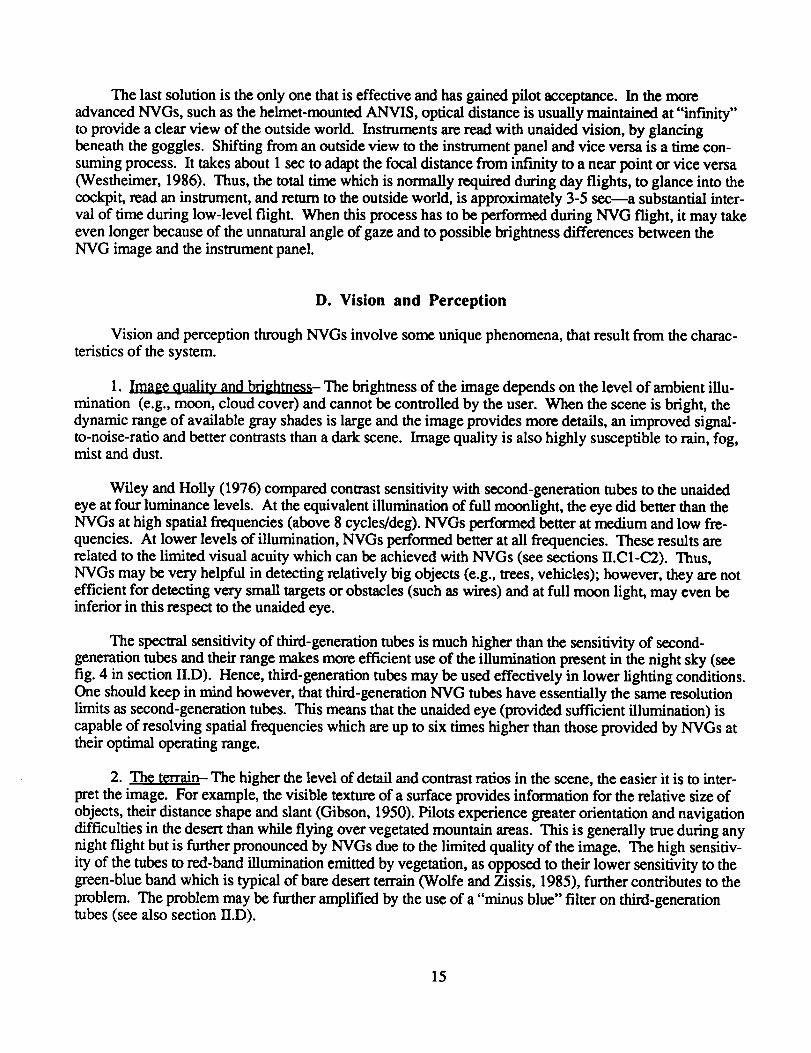
1. Image quality and brightness-- The brightness of the image depends on the level of ambient iUu-
mination (e.g., moon, cloud cover) and cannot be controlled by the user. When the scene is bright, the
dynamic range of available gray shades is large and the image provides more details, an improved signal-
to-noise-ratio and better contrasts than a dark scene. Image quality is also highly susceptible to rain, fog,mist and dust.
Wiley and Holly (1976) compared contrast sensitivity with second-generation tubes to the unaided
eye at four luminance levels. At the equivalent illumination of full moonlight, the eye did better than theNVGs at high spatial frequencies (above 8 cycles/deg). NVGs performed better at medium and low fre-
quencies. At lower levels of illumination, NVGs performed better at all frequencies. These results are
related to the limited visual acuity which can be achieved with NVGs (see sections II.C1-C2). Thus,
NVGs may be very helpful in detecting relatively big objects (e.g., trees, vehicles); however, they are not
efficient for detecting very small targets or obstacles (such as wires) and at full moon light, may even beinferior in this respect to the unaided eye.
The spectral sensitivity of third-generation tubes is much higher than the sensitivity of second-
generation tubes and their range makes more efficient use of the illumination present in the night sky (see
fig. 4 in section II.D). Hence, third-generation tubes may be used effectively in lower lighting conditions.One should keep in mind however, that third-generation NVG tubes have essentially the same resolution
limits as second-generation tubes. This means that the unaided eye (provided sufficient illumination) is
capable of resolving spatial frequencies which are up to six times higher than those provided by NVGs attheir optimal operating range.
2. The terrain- The higher the level of detail and contrast ratios in the scene, the easier it is to inter-
pret the image. For example, the visible texture of a surface provides information for the relative size of
objects, their distance shape and slant (Gibson, 1950). Pilots experience greater orientation and navigation
difficulties in the desert than while flying over vegetated mountain areas. This is generally true during anynight flight but is further pronounced by NVGs due to the limited quality of the image. The high sensitiv-
ity of the tubes to red-band illumination emitted by vegetation, as opposed to their lower sensitivity to thegreen-blue band which is typical of bare desert terrain (Wolfe and Zissis, 1985), further contributes to the
problem. The problem may be further amplified by the use of a "minus blue" filter on third-generationtubes (see also section II.D).
15
3. Distance estimation- Both ANVIS and "cat's eyes" provide a 1:1 world image. Nevertheless,
NVG users tend to overestimate distances. Objects are perceived as being further away (or smaller) than
they really are (Brickner, Wagner, and Gopher, 1987). The potential danger of such misperceptions at
low level flight, or during landing can easily be imagined.
These misperceptions seems to be related to the phenomenon of"instrument myopia" (see also sec-
tion HI.D). Although the image is projected to optical inf'mity, the observer tends to focus his eyes to acloser distance (Roscoe, 1985). Hence, the feedback that the brain receives from the eyes' lens, "tells" it
that the observed image is closer than it really is. However, since the angular projection of objects on the
retina corresponds with their real distance, they are interpreted as being smaller or further than they really
are. In other words, the retinal image of an object which is perceived as remote, is interpreted as
representing a big object, while an identical retinal image of an object which is perceived as being close, isinterpreted as representing a small object. This relation is known as "Emmert's law" or the "size-distanceinvariance hypothesis" (e.g., Epstein 1965).
The use of a negative diopter for the goggles to compensate myopia, reduces the size of the image
below its original 1:1 ratio. This may further amplify distance underestimation. Additional problems mayoccur if the optical paths of the two tube are not exactly parallel (see also section IV.B).
E. Slope Estimation
Gibson and Comsweet (1952) defined three frames of reference with which slant can be estimated.
It can be estimated relative to: 1) the line of regard (optical slant); 2) some environmental frame of refer-
ence such as the horizon (geographical slant); 3) and some adjacent surface or object (relative slant). Two
phenomena related to incorrect judgment of slopes have been reported by pilots (Brickner, Wagner, andGopher, 1987).
1. The _'adient of near slopes are often underestimated by the pilot, particularly during approach to
landing (Brickner, Wagner, and Gopher, 1987). It is obvious that pilots can not rely on "optical slant,"due to their constantly changing spatial orientation. During approach to landing the pilot must concentrate
most of his visual attention in the landing area. Considering the restricted field of view, this would mostoften leave the pilot with only relative cues for slant estimation. However, because of the limited resolu-
tion and contrast ratios provided by NVGs, the visible texture on available reference surfaces is also poor
and their slant may be misperceived as well (Gibson, 1950). Accurate slope estimation is essential during
low-level flight, particularly when selecting a landing area. If the selected landing area is sloped, there is a
risk that the helicopter may roll over or the tail rotor may hit the ground upon landing.
2. The inclination and slopes of distant elements in the scene may also be misperceived. It may be
difficult for pilots to distinguish elevations from depressions and to estimate gradients. The tendency is
particularly pronounced in desert areas where there is limited terrain texture and a large variety of unpre-dictable shapes. During good visibility conditions, a pilot would rely predominantly on "geographical"
slant cues to estimate distant slopes (e.g., the horizon or a large flat area). However, NVGs limited fieldof view may reduce the availability of such reference areas in the immediate field of view. Limited resolu-
tion and contrast ratios may reduce the usefulness of those surfaces which axe visible. These difficulties
may be particularly pronounced under marginal lighting conditions.
16

A distorted representation of the world may lead to disorientation and vertigo. It should be empha-
sized, however, that the incidence of vertigo is much lower during NVG flights than it is during unaided
night flights. The improved world view provided by NVGs enhances object recognition, while general
spatial orientation is maintained by looking around them.
F. Instability of the World Image
Pilots report that they occasionally sense apparent movement in the world image during NVG flights
(Brickner, Wagner, and Gopher, 1987); the world appears to be moving when it is, in fact, stable. This
illusion is particularly enhanced by sudden or rapid head movements. The illusion may occur as a result of
the distance between the eye and the phosphor screen of the intensifier tube. When an unaided eye
watches a moving object, relative movement is induced on the retina. When the eyes move and the world
is stable, the same relative movement occurs, however, the brain knows how to distinguish between thetwo types of movements and interpret them correctly (Anstis, 1986).
While wearing NVGS, if a pilot moves his head, the world image moves as described above. Now
however, the image is not projected directly onto the retina. Rather it is projected onto the phosphor
screen of the intensifier tube, which is approximately 4 in. in front of the retina, and only then onto the
retina. Because of the longer radius of movement, the rate of movement on the phosphor screen is higher
than would be expected by a natural retinal image (fig. 9). Thus, a pilot may perceive that a stationary
object is moving in a direction opposite to the head movement.
To overcome this effect, the pilot has to learn to perform slow, controlled head movements from thecenter to each side and, whenever possible, to avoid abrupt, rapid movements.
NVG IMAGE
IMAGE
Figure 9.- Schematic description of image motion on the retina and on the NVG tubes. When the head is
turned 90 ° to the right, images on the NVGs move along the large outer circle, while retinal images
are expected to move along the small inner circle.
17
G. Brightness and Dazzling
In fwst and second-generation tubes, source of bright light such as city lights, car headlights, flares,
or the direct view of the moon, create a "blooming" effect. This reduces the quality of the whole imageand can be very disturbing (Bohm,1985). Third-generation tubes have a more efficient AGC, which
adapts the average brightness of the whole image to the momentary level of illumination. Thus, the dis-
turbing effect of blooming is much less of a problem. However, the AGC reaction to bright light also
reduces the total brightness of the screen and its dynamic range of gray shades (which is low to begin withbecause of the low peak brightness of NVG displays). Hence, whenever possible, a pilot should avoid
looking directly at bright sources of fighting.
H. Monochrome Images
The color of the image is determined by the type of phosphor used on the screen. Most contempo-
rary NVGs use fast-response green or yellow-green phosphors (e.g., P-20). The system generates amonochrome image in which the "gray shades" are actually various intensities of green. In fact, unaided
night-vision is monochrome as well, because the rods are insensitive to color differences. However, there
are various sources of information in the outside world and particularly within the cockpit, in which color
plays a vital role. Inside the cockpit, warning lights have to be modified or eliminated, to maintain NVGcompatibility (Breitmaier and Reetz, 1985; see also section II.D).
Colored sections on instruments and on maps may be seen with the unaided eyes. However, since
NVG-compatible lighting is narrow-band and homogenous, it is very difficult to distinguish amongdifferent hues. Thus, pilots must learn not to rely on color vision. It is essential that all important infor-
mation in the cockpit has redundant coding so that it may be acquired without relying on color vision. In
addition, maps, aerial photographs, and other information charts, must be adapted to NVGs lighting such
that different hues also create distinct brightness levels so that they may be distinguished from each other.
Outside the cockpit, obstruction lights and aircraft navigation, anticollision or formation lights carrycrucial color information. Sources of red lighting may pose additional problems; because of the extreme
red-band sensitivity of NVGs, small or remote sources of red light may seem much brighter than theyreally are, resulting in poor distance estimations. Since it is impossible to create an "NVG compatible
world" outside the cockpit, pilots must be highly aware of the nature of the visual aids they are using andinterpret the information it provides accordingly.
The monochrome image provided by NVGs and its range of wavelength sensitivity are inherentcharacteristics of the system and are not expected to change in the near future. Thus, as long as NVGs are
used for helicopter operations, pilots will have to adapt to their limitations and learn to compensate for theirmodified and sometimes misleading representation of the world.
I. Symbology in NVGs
In spite of the fact that current-technology, helmet-mounted NVGs provide "see around" capabilities,
reading panel mounted displays is time consuming and imposes additional workload. During low-level
flight and hover it is particularly important for the pilot to keep his eyes outside the cockpit. (Simmons
et al., 1985). Thus the pilot is not capable of concurrently reading flight instruments. The problem may
be partially solved by superimposing synthetic flight symbology on the world image (fig. 10). The
18

technical aspects of this possibility have been discussed in section II.E. Although superimposed flight
symbology may reduce pilot workload it also involves some potential human factors problems of whichboth the designer and the user should be aware.
1. Brightness- If the symbology is seen through the goggles (as depicted in fig. 5 in section II.E)
and if it is too bright, it may drive the automatic brightness control to reduce the brightness of the whole
image, thus reducing its quality.
2. Bin0_01_r Riv_llry- The symbols are presented to one eye only, (usually the fight eye which is the
dominant eye in approximately 70% of the population; Porac and Coren, 1981). This may cause differ-ences in the average brightness level of the two images, and induce different levels of dark adaptation.
The eye which receives the darker display has longer reaction times than the other eye. The differences inreaction time may cause illusions of motion in depth like the Pulfrich pendulum illusion (Rogers and
Anstis, 1972). In addition, the deferences between the images may interfere with the fusion of the two
images into one coherent binocular image, and enhance binocular rivalry (e.g., Arditi, 1986). If the sym-bols are presented to the dominant eye, the user may suppress the other eye without awareness and attrib-
ute the poor quality of the image to other causes. If the nondominant eye views the symbols, the user may
alternate from one eye to the other, watching each of the images separately. In either case, the user would
lose part of his field of view, some contrast sensitivity, and all binocular depth cues.
TRACK
ANGLE HEADING
ERROR / DISTANCE TO GO
GROUND _ _ TO WAYPOINT
pEEp\ _ /,,xEo _ \ / /-_ RADAR.OR,.G.,/', VALT" *'
,,.,0 GO >'I ' [] -_I F,o T l:
"- / lI\ I iv.:.,<._./ i ,,,,o_,,Y
IAL T
DRAFT MODE}
SYMBOL
Figure 10.- Example of NVG superimposed symbology.
3. Focal dist0_n?¢.-- Both the world view and the symbology are seen through the same optical system
and are, therefore, projected exactly to the same focal distance ("infinity"). However, pilots tend to per-ceive the symbols as being closer to their eyes than the world view and find it difficult to observe both
types of information simultaneously, even though they are superimposed on the same device. The danger
is that the pilot might "forget" to look at the world and spent most of the time watching flight symbology,
19

thereby ignoring obstacles and other crucial information. Similar observations have been made by Apache
pilots using a helmet-mounted FUR display system (Hart and Brickner, in press; also see section V).
4. Symbology distribution- NVGs field of view (40°), is large in comparison with that provided on
fighter aircraft and helicopter head-up displays (approximately 20 ° horizontal) and conventional panel-
mounted displays (approximately 10°). It is possible to present all of the symbols at the center part of thedisplay, thus reducing the likelihood that any information might be missed. This solution is also techni-
cally simpler because it does not require a wide-field-of-view symbol generation system. Alternatively,the distribution could be across the whole area of the display, minimizing its interference with the central
areas of the world image. To optimize the f'mal design, the specific content of information and its impor-tance during various mission phases should be considered. One should bear in mind, however, that
NVGs have been designed to present the clearest possible world image. Flight symbology is importantand sometimes vital, but it should not interfere with the primary source of information--the world view.
J. Visual Fatigue
Many pilots report visual fatigue or general fatigue during or after NVG flights. Large individual
differences exist, however. Some pilots seem to get tired after as little as 1 hr of flight, while others feel
that NVG flight doesn't differ in this respect from flight without goggles on a bright night (Stone, 1984).
Visual fatigue may have some detrimental consequences on performance. For example Schmidt,
Abel, Dell'Orso, and Daroff (1979) found that fatigue results in less efficient eye scan patterns. Gregoryand Zangwill (1963) found that fatigue increases susceptibility to the autokinetic motion illusion (in which
a small source of motionless light is seen as floating in space), a major contributor to disorientation andvertigo.
Although visual fatigue is a well-known experience, it does not have an accurate scientific definition.The main contributors to visual fatigue may be:
1. _- The extra weight that goggles place on the pilot's head, particularly if they arenot well-balanced, may cause neck-muscle strain. The required head movements may further enhance the
strain. Neck-muscle strain may often lead to a feeling of visual fatigue (Price and McLean, 1985).
2. Physiological contribetors- The requirement to monitor continuously an artificial image that emits
homogenous, narrow-band light and the constant effort to required spot indistinct targets may cause eyefatigue directly (Stone, 1984). In addition, inappropriate diopter settings (too high, too low, or not bal-
anced), intensifier tubes which are not exactly parallel, external or internal light sources that cause
"blooming," and a dark, noisy image may all contribute to or enhance visual fatigue.
3. Psycholo_cal factors- Psychological stress and anxiety generally impair performance in manykinds of tasks (e.g., Eysenck, 1982). Mandler (1979) proposed that stress acts as a distractor and
demonstrated its effect on reducing working memory capacity. The strain and high workload imposed by
low-level flight through a narrow visual window of limited quality, pilot's uncertainty about their ability todetect obstacles, such as wires; and the general stress involved in flying in a dangerous and sometimes
hostile environment may involve extra visual strain and create visual fatigue. For example, Pettyjohn
(1977) found a high correlation between oxygen consumption and mode of flying; oxygen consumptionwas highest during NOE flight with NVGs. Pettyjohn interpreted the large differences found between
easy and difficult flight modes, as evidence of stress rather than physical effort.
20

Physicalfatiguecanbereducedby maintaininggeneralphysicalfitness, strengthening neck muscles,
maintaining an appropriate sitting posture and balancing the NVGs (Department of the Army, Field Man-
ual, 1983). Physiological sources of fatigue can be minimized by good NVG maintenance, selecting
optimal settings, and controlling every possible source of interfering light and reflections. Psychological
fatigue may be controlled by providing the pilots with all of the knowledge and skills required for the job
and by sustaining their level of expertise through regular recurrent training, thus minimizing pilots' work-
load (e.g., Schneider and Fisk, 1982).
K. Individual Differences
Pilots' abilities to make efficient use of NVGs, varies significandy. For example, there are individ-
ual differences in peoples' abilities to adapt to new visual representations (e.g., Warren and Platt, 1975),
learning abilities, susceptibility to illusions and disorientation Anstis, 1986), focal distance (Leibowitz andOwens, 1975), abilities to detect and identify obstacles and targets, susceptibility to diplopia (double
vision) and eye suppression (Warren, Genco, and Connon, 1984), visual fatigue, and the ability to shiftback and forth from NVGs to unaided vision (Westheimer, 1986).
Although large interindividual differences, among experienced NVG pilots in visual acuity and con-trast sensitivity, have been measured in the laboratory (Price and McLean, 1985), only some pilots are
aware of their limited abilities with NVGs. Many pilots experience visual fatigue after relatively short
periods of flight and some pilots resent the requirement to use them. To help pilots improve their NVG
performance, reduce fatigue or select only those pilots who are likely to succeed in flying with NVGs, it
will be necessary to identify the sources of individual differences, devise screening tests sensitive to these
factors, and develop improved training methods for those skills that can be improved through training.
Some of the following parameters may be related to NVG ability:
1. ]_,ghl..Yi,_i_- Night-vision and NVG vision might be correlated, although NVGs are not physi-
ologically the same as "night vision," but rather mesopic "twilight vision" in which both rods and cones
are active to a certain degree (Price and McLean, 1985).
2. Contrast sensitivi _ty- The ability to distinguish adjacent areas of varying contrast ratios is only
partially correlated with visual acuity (Ginsburg, 1984). Since pilots vary in their ability to discriminatelow-contrast differences with NVGs (Price and McLean, 1985), contrast sensitivity may be a valid pre-
dictor of NVG performance.
3. Focal distance- The eyes have a strong tendency to accommodate to a relatively short distance.
This tendency is enhanced when viewing an image which is displayed on an instrument, even if the dis-
play is optically projected to infinity (Roscoe, 1985; see also sections Ill.D, IV.C). The NVG world
image, is projected to inf'mity, however, if the eyes have accommodated to a shorter distance, the imagewill be blurred and objects may appear to be smaller or more distant than they really are (see sec-
tion IV.C,D). Large individual differences in focal distance, as measured with an empty or a dark field of
view, have been reported (Leibowitz and Owens, 1978). For example, Simonelli (1980) found that the
dark-focus distance of a population of young flight recruits with perfect visual acuity was 1.19 diopters(84 cm) with a standard deviation of 1.5 diopters (66 cm). Any pilot who tends to accommodate to a near
distance may not perform well with NVGs (Roscoe, 1987). However, it may be possible to improve focal
distance through biofeedback training methods (Roscoe and Couchman, 1987).
21
4. Corrected vision- Helicopter pilots in the US Army may have corrected vision. However, the
necessity of using eye glasses or contact lenses is determined by tests of day vision only (Price andMcLean, 1985). Some pilots with perfect day vision may need correction at night, particularly for myopia
(shortsightedness; see section III.D). When using the ANVIS, a pilot may correct his vision either by
using his glasses or by adapting the ocular lens of the ANVIS (fig. 2). However, the ANVIS can only
compensate for near-sightedness or far-sightedness, while astigmatism has to be corrected by eyeglasses
or contact lenses. Some pilots may not be aware of their deficient night-vision or may prefer not to use
glasses for other reasons. In addition, Leibowitz and Owens (1978) showed that myopic subjects tend tohave a much closer focal distance than do subjects with normal vision. Taken together, problems related
to corrected vision (or to vision that requires correction) may significantly limit pilots' abilities to use
NVGs adequately.
5. Eye suppression- In approximately 70% of the population, the right eye is dominant (Porac and
Coren, 1981). However, this isn't an "all or none" phenomenon. Relative dominance varies along a
continuum. One important measure of eye dominance is ocular rivalry. People with strong eye dominance
have a stronger tendency to suppress the image of the nondominant eye. Eye suppression may bring about
monocular vision which produces a diminished field of view, and reduced contrast sensitivity (Arditi,1986). Eye suppression is enhanced by differences between the images viewed by the two eyes (e.g.,
when the tubes have different intensities), and by divergence of the two optical axes (e.g., when the tubes
are not properly aligned).
In summary, the "ideal" NVG pilot is one with perfect day and night visual acuity and high-contrastsensitivity, a distant focal point, and well-balanced eye dominance. However, since even the highly
selective population of pilots is rarely perfect, it is important to develop methods of diagnosing potential
difficulties in NVG flying and to devise appropriate training programs adapted to individual needs. Indi-vidual differences must be taken into account: it is particularly dangerous when highly experienced pilots
or flight instructors with little insight about the potential difficulties that other pilots may have with NVGs
wain or lead other pilots who have more limited capacities.
V. LIGHT INTENSIFIERS VERSUS THERMAL IMAGING
In this section light intensifiers will be compared to thermal imaging (TI) or forward-looking infrared
(FLIR) systems. A detailed discussion of human factors in helicopter FLIR systems may be found in Hart
and Brickner (in press).
A. Thermal Imaging Systems
All objects having a temperature greater than absolute zero (0 K or -273°C) emit electromagnetic
radiation over a continuous range. The amount of emitted energy depends on the object's temperature and
its surface condition, or emissivity. The core of the thermal imaging (TI) system is a sensor (or an array
of sensors) which is sensitive to heat or infrared radiation in the 3-5 gm or 8-14 gm band. The sensor
scans a given area (through an optical system and a scanner) and transforms the detected energy into
electrical pulses which are processed, transformed into a video signal, and displayed on a CRT. Thus, thedistribution of emitted heat in a scene is presented as an image in the visible band (Lloyd,1975).
22

B. Characteristics of the Thermal Image
Unlike light intensifiers, TI systems do not depend on the ambient light in the environment and may
produce a visible image even in total darkness. In addition, they are capable of"seeing" through dust,
smoke, and fog (although water vapor absorbs some infrared radiation), and detecting targets through
camouflage. These characteristics increase the operational envelope of TI systems beyond the capabilitiesof the eyes or vision with light intensifiers (Bohm, 1985).
The quality of the thermal image and the effective range of the system, depend on characteristics of
different components, the distribution of emitted heat in the scene, and on atmospheric conditions (Lloyd,
1975). Under good viewing conditions, the effective range of FLIR systems is considerably higher than
that of NVGs (of similar magnifications); hot targets may be detected from long distances (Bohm, 1985).
The thermal image represents the distribution of emitted heat in the scenery while direct optical
images represent the distribution of reflected visible light. Thus, visual displays of thermal image deviate
considerably from the same scene viewed by an unaided eye or recorded by a video camera. These unique
characteristics may bring about some difficulties in image interpretation (Hart and Brickner, in press).
1. Shading- Typically, direct optical images are illuminated by a single remote source of light (e.g.,the sun or the moon) that is reflected by objects in the scenery. Hence, the image includes attached and
cast shades which consistently reflect the direction of illumination. This shading is an important source of
information in interpreting the three-dimensional structure of the terrain and seeing surface relief (Todd and
Mingolla, 1983). In contrast, thermal images are created by emitted heat. Various shades of gray repre-
sent different temperatures. Although these may coincide with real shading (e.g., a shaded area may be
cooler than an illuminated area), more often, the meaning of bright and dark areas in a TI is significantlydifferent than it is in a video image. Thus, an attempt to apply familiar perceptual rules of thumb to inter-pret a TI may result in serious errors.
2. Changes over time- The distribution of emitted temperatures changes constantly as a function of
time. In general, the environment cools during the night, which results in reduced temperature contrasts.
Thus, the night and early morning hours degrade image quality. Prolonged and uniform heating may alsoreduce thermal contrasts. In addition, the temperatures of specific components in the scene (e.g., vegeta-
tion and soil) may "cross over" at certain times, thereby eliminating the contrast between them (Berryet al., 1984).
3. Polarity- The TI may represent hot areas as light shades ("white hot") and cool areas as darker
shades or vice versa ("black hot"), depending on the option selected by the pilot. Either polarity may seemto be more natural in different situations. For example, the sky is always cold and is usually perceived asa bright area in the image. However if white represents cold, then shaded area which are also cooler will
also be bright, in contrast with their natural appearance.
4. Gain and l_v_l- At any given moment, the TI system displays only part of the thermal variabilityin the scenery (Biesel and Rohlf'mg, 1986). Gain and level controls determine the range of detectedthermal contrasts represented on the CRT. The selected condition has a crucial effect on the content of the
image. For example, if a large range of gray shades is selected to represent thermal variations within a hot
target, only a few gray shades may remain to represent the background.
23

5. Heat sources- Heat-producing objects, such as vehicles, have a unique "thermal signature." Forexample, a tank may have a hot spot at the engine (in fact the engine may be seen through the body of the
tank), at the treads (friction heat), and at the cannon (if it has fired lately). Thus, the thermal appearance of
the tank deviates significantly from its familiar optical appearance.
C. FLIR Helicopter Flying
Recently, FLIR systems have been installed in many military and some civilian helicopters to enable
night flights and target detection and acquisition through the TI. The most advanced operational system isthe one installed in the AH-64 (Apache); the pilot night vision system (PNVS).
The PNVS is based on a turret-mounted FUR located on the nose of the helicopter, 3.5 m in front and 1.2
m below the pilot's eye position (fig. 11). The FL1R is slaved to the position of the pilot's helmet,
allowing the pilot to move the 30 (vertical) by 40 ° (horizontal) instantaneous field of view through a "field
of regard" of :L-90° azimuth, 20 ° elevation, and 45 ° depression. The infrared sensor consists of an array of180 detectors which provides 360 lines of resolution. This information is transformed into a 875-line
video image which is displayed on a 1.92 cm combining lens (a monocle) mounted on the helmet
immediately in front of the pilot's right eye (fig. 12).
D. Comparison of Thermal Imaging and Light Intensifiers
The following is a concise comparison between TI and NVG as exemplified by the PNVS (the
AH-64 TI system) and the ANVIS (third-generation NVG). The comparison relates to generalcharacteristics inherent in the different technologies, as well as to more specific features of the PNVS andthe ANVIS, and to the task of flying a helicopter at night.
IlluminatiQn
PNVS: It does not require ambient illumination and is useful during the day and the night. Dependson thermal variability in the scene.
ANVIS: This requires some ambient illumination at night and cannot be used during the day (it isoverly sensitive to bright light).
TADS/PNVSTURRET
Figure 11.- AH-64 (Apache) with PNVS.
24
ORIGINAL PAGE IS
OF POOR QUALITY
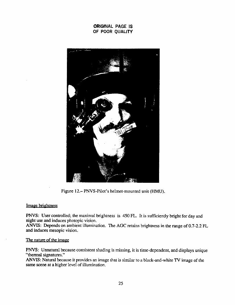
Figure 12.- PNVS-Pilot's helmet-mounted unit (HMU).
Image brightness
PNVS: User controlled; the maximal brightness is 450 FL. It is sufficiently bright for day andnight use and induces photopic vision.
ANVIS: Depends on ambient illumination. The AGC retains brightness in the range of 0.7-2.2 FLand induces mesopic vision.
The nature of the image
PNVS: Unnatural because consistent shading is missing, it is time-dependent, and displays unique"thermal signatures."
ANVIS: Natural because it provides an image that is similar to a black-and-white TV image of thesame scene at a higher level of illumination.
25
F.itda.gLK¢
PNVS: 40 ° horizontal by 30 ° vertical.ANVIS: 40 ° diameter, round FOV.
PNVS: :_)0° inazimuth,20°inelevationand 45° indepression.Fieldof regardislimitedby turret
movement capabilities,but isunobstructedwithinthatrange.
ANVIS: Fieldof regardrestrictedonly by head movement limitationsand obstructionscrewed bythebody of the helicopter.
See around capabilities
PNVS: The FOV of the right eye practically blocked by HMU (because of brightness differences).The left eye is unobscured.
ANVIS: The central FOV of both eyes blocked by the goggles. Peripheral vision possible, but isrestricted by dark adaptation level.
De m'ees of freedom for image movement
PNVS: Ithas only 2 degreesof freedom, azimuth (yaw) and elevation(pitch).The turretedsensorisindifferenttoany otherdirectionofhead motion.
ANVIS: The system is helmet mounted, thus the image adapts to head movements in all 6 degreesof freedom.
Resolution
PNVS: This depends primarily on size and number of sensors, (approximately 360 horizontal linesin PNVS).
ANVIS: Nearly 650 x 650 pixels at the diameter of the image (third-generation tubes).
Binocular vision
PNVS: None, since the system is monocular. The unaided eye may be used to obtain peripheral
cues. However, images from both eyes do not integrate, producing possible binocular rivalry.ANVIS: Binocular depth perception is induced through two parallel tubes, although pilots reportreduced depth cues relative to unaided vision.
Sensor location
PNVS: Strongly offset from pilot's eye position (3.5 m in front and 1.2 m below pilot's eye). Itmay invoke apparent motion, parallax, and incorrect distance estimation. The sensor is located out-
side the cockpit, thus symbology is required to preserve spatial orientation inside the cockpit.ANVIS: Near pilot's eyes (approximately 10 cm in fron0. Apparent motion may occur during rapid
head movements. The sensor is located inside the cockpit. Spatial orientation is preserved byviewing instrument panel and windshield, through the ANVIS.
26

Optical path
PNVS: Indirect. The signal from the sensor is amplified, processed, and transformed into videoformat.
ANVIS: Direct. The amplified signal is directly transmitted onto a phosphor screen.
$u_verimposed symbology
PNVS: Flight and target acquisition symbology are superimposed on the thermal image.ANVIS: Currently not available. In systems under development symbology may be added by
incorporating a display into the optical path.
Target aco_uisition
PNVS: The FLIR and weapon systems are slaved to head movements which are monitored by a
helmet tracking device. The system provides off-boresight target acquisition capabilities.ANVIS: Currently not integrated into any weapon or target acquisition system. Head movementsare not monitored.
Ran ge of target detection
PNVS: Two to three times better than ANVIS (at good viewing conditions for both systems),
depends on thermal contrasts. Very high for hot targets.
ANVIS: Relatively limited, depends on ambient illumination and contrasts. High for illuminated
targets.
Atmospheric conditions
PNVS: Capable of "seeing" through dust, haze, and smog. Restricted by fog and rain.
ANVIS: Significantly degraded by dust, haze, and fog.
Environmental requirements
PNVS: To prevent noise, sensor requires intensive cooling (approximately 70 K).
ANVIS: Highly sensitive and has to be protected from intense ambient light. Requires special
adjustment of cockpit lighting. Light sources may cause "blooming" and reduce image brightness.
Training requirements
PNVS: Relatively long; approximately 30 flight hr for an experienced pilot.
ANVIS: Relatively short; 5-10 flight hr for an experienced pilot.
Wei_,ht of head unit
PNVS: Helmet display unit weighs approximately 370 g and is slightly unbalanced laterally.
ANVIS: Weighs approximately 850 g including the battery housing which effectively balances the
weight of the goggles.
27
Zoag_w.gght
PNVS: Including sensor, optical components and signal processing units, is very high. Affectspower and balance considerations of the whole platform.
ANVIS: Very low (850 g).
Price
PNVS: Very high, hundred thousands of dollars.ANVIS: Low, thousands to tens of thousands of dollars.
Reliability_ and maintainability_
PNVS: Relativelypoor,because of system complexity and sophistication.
ANVIS: Very good, because of system simplicityand modularity.
In summary, the PNVS has aconsiderableoperationaladvantage over the ANVIS: itoperatesinde-
pendentlyof ambient lightand has a greaterrange even under adverseconditionsthanthe ANVIS. Fur-
thermorc,the PNVS isa complete,integratedsystem which provides allof thenecessaryinformationfor
flying as well as target acquisition. The price that has to be paid for these advantages is: a high cost, high
weight, significantly more human-factors problems (Hart and Brickner, in press), and longer training
requirements, because of the remote location of the PNVS sensor, the monocular display and the nature of
the thermal image.
E. Combining NVGs and FLIR
The drive to combine NVGs and FLIR came primarily from the fighter aircraft community. During
the last decade, various attempts have been made to use low-light-level TV or NVGs to fly jet fighters at
night (Bull, 1985). The main drawback was the limited viewing range of NVGs. Fighter aircraft fly at
higher speeds and altitudes than helicopters, and therefore, require longer viewing distances, particularlyin the forward direction.
Recently, efforts have been made to develop airborne FLIR systems for fighter aircraft (e.g.,
LANTIRN, Pathfinder). One of the major issues was where to display the FLIR image; panel-mounted
displays are very restricted in field of view (in addition to other obvious disadvantages), whereas helmet-
mounted displays have not yet come of age in fighter aircraft. The solution required the development of
high brightness, wide field of view, head-up displays (HUD; Warren, Genco, and Connon, 1984).
However, on a HUD, only a boresight image of less than 30 × 20 ° can be displayed; hence, the combina-
tion of a boresight FLIR with the"look around" capabilities of helmet-mounted NVGs seemed to be
attractive. Nevertheless, one crucial problem remained: it is impossible to view the FLIR image on the
HUD through the NVGs without severe degradation. Thus, the solution required the development of a
new type of NVGs. One example of such a system the "Cat's Eyes" (GEC Avionics).
"Cat's eyes" have a combining eye piece that allows direct see through when the NVGs are turned
off (fig. 13) and a head tracker. The NVGs are shut off automatically whenever the pilot's head is turned
towards the HUD. Thus, the pilot is provided with a continuous "field of regard" which consists of a
20 × 30 ° boresight FLIR image with superimposed HUD symbology and a round 30 ° helmet-mounted,
28
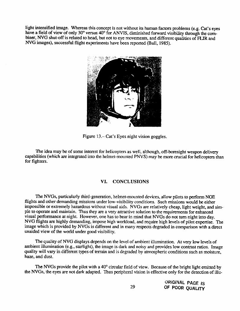
light intensifiedimage.Whereasthisconceptis notwithoutits humanfactorsproblems(e.g.Cat'seyeshaveafield of view of only 30° versus40° for ANVIS, diminishedforwardvisibility throughthecom-biner,NVG shut-offis relatedto head,butnot to eyemovements,anddifferentqualitiesof FLIR andNVG images),successfulflight experimentshavebeenreported(Bull, 1985).
Figure 13.- Cat'sEyesnightvision goggles.
Theideamaybeof someinterestfor helicoptersaswell, although,off-boresightweapondeliverycapabilities(whichareintegratedinto thehelmet-mountedPNVS)maybemorecrucial for helicoptersthanfor fighters.
VI. CONCLUSIONS
The NVGs, particularly third-generation, helmet-mounted devices, allow pilots to perform NOE
flights and other demanding missions under low-visibility conditions. Such missions would be either
impossible or extremely hazardous without visual aids. NVGs are relatively cheap, light weight, and sim-ple to operate and maintain. Thus they are a very attractive solution to the requirements for enhanced
visual performance at night. However, one has to bear in mind that NVGs do not turn night into day.NVG flights are highly demanding, impose high workload, and require high levels of pilot expertise. The
image which is provided by NVGs is different and in many respects degraded in comparison with a directunaided view of the world under good visibility.
The quality of NVG displays depends on the level of ambient illumination. At very low levels of
ambient illumination (e.g., starlight), the image is dark and noisy and provides low contrast ratios. Imagequality will vary in different types of terrain and is degraded by atmospheric conditions such as moisture,haze, and dust.
The NVGs provide the pilot with a 40 ° circular field of view. Because of the bright light emitted by
the NVGs, the eyes are not dark adapted. Thus peripheral vision is effective only for the detection of illu-
ORIGINAL PAGE IS29 OF POOR QUALITY

minated objects, which are primarily inside the cockpit. Pilots must compensate for the relatively smallfield of view by constant head movements. However, rapid head movements may result in illusions of
apparent motion. Despite the binocular vision which is provided by the two parallel NVG tubes, depthperception is often inaccurate; pilots report difficulties in distance and slope estimation.
The ANVIS NVGs provide "see around" capabilities and enable the pilot to monitor panel-mounted
flight insmn'nents by looking beneath the goggles; however, this is a time-consuming process. Addingsuperimposed flight symbology to the NVGs may reduce workload, but may, in turn, create new
problems which can affect image quality and enhance undesirable effects such as binocular rivalry andinappropriate accommodation.
It is often assumed that NVG flights are "no problem." However, the large individual differenceswhich exist among pilots in their ability to make safe and efficient use of NVGs suggests otherwise.
Some pilots may adapt to NVGs rapidly and feel comfortable while using them, while others may suffer
from excessive visual fatigue and feel uncomfortable even after short periods of flight. All pilots requireregular use to sustain their level of expertise (Brickner, Wagner, and Gopher, 1987).
Neither the applied nor basic literatures provides us with sufficient understanding of the psychologi-cal and physiological aspects of flight with NVGs. Only small parts of the vast body of vision research
literature is related to night-vision and only a fraction deals with mesopic vision which is created by thebrightness levels of the NVGs. Individual differences, which are extremely important for the selection and
training of NVG operators, have been traditionally ignored by cognitive psychologists and have not been
studied systematically. Additional basic and applied research is required to improve our understanding of
the human-factors issues involved in night flight in general and in flight with NVGs and other types ofvisual aids in particular.
3O

REFERENCES
Anstis, S.: Motion perception in frontal plane: Sensory aspects. In K. R. Boff, L. Kaufman, and J. P.
Thomas, eds., Handbook of Perception and Human Performance, Vol. I, oh. 16. New York: John
Wiley and Sons, 1986, pp. 16.1-16.27.
Arditi, A.: Binocular vision. In K. R. Boff, L. Kaufman, and J. P. Thomas, eds., Handbook of
Perception and Human Performance, Vol. I, ch. 23. New York: John Wiley and Sons. 1986,
pp. 23.1-23.41.
Berry, J.; Dyer, R.; Park, R.; Sellers, A.; and Talton, M.: PNVS Handbook, Ft. Rucker, AL: US Army
Training and Doctrine Command, 1984.
Biesel, H.; and Rohlf'mg, T.: Real-time simulation of FLIR imagery. Proceedings of the Interservice/
Industry Training Systems Conference, November 1986, pp. 37-42.
Bohm, H. O. V.: FLIR NVG and HMD/S systems in helicopters operation---review. In Visual Protec-tion and Enhancement, AGARD CP-379, Neuilly-Sur-Seine, France, 1985, pp. 2.1-2.27.
Breitmaier, W. A.; and Reetz, F.: Visual and spectroradiometric performance criteria for night vision
goggles (NVG) compatible aircraft interior lighting. In Visual Protection and Enhancement,
AGARD CP-379, Neuilly-Sur-Seine, France, 1985, pp. 5.1-5.11.
Brickner, M. S.; Wagner, M.; and Gopher, D.: Human factors in NVG flights. Technical Report Human
Engineering Branch, Israel Air Force, 1987.
Bull, G. C.: Night vision by NVG with FLIR. In Visual Protection and Enhancement, AGARD CP-379,
Neuilly-Sur-Seine, France, 1985, pp. 10.1-10.7.
Draeger, J.; Hanke, K.; and Wirt, H.: Particular problems of airworthiness from an ophthalmologicalview. In Visual Protection and Enhancement, AGARD CP-379, NeuiUy-Sur-Seine, France, 1985,
pp. 11.1-11.3.
Epstein, W.: Nonrelational judgments of size and distance. American Journal of Psychology, vol. 72,
1965, pp. 335-338.
Eysenck, M.W.: Attention and arousal: Cognition and performance. Berlin: Springer-Verlag, 1982.
Genco, L. V.: Night vision support devices: Human engineering integration. In Visual Protection and
Enhancement, AGARD CP-379, Neuilly-Sur-Seine, France, 1985, pp. 6.1-6.8.
Gibson, J. J.: The Perception of the Visual World. Boston: Houghton Mifflin, 1950.
Gibson, J. J.; and Cornsweet, J.: The perceived slant of visual surfaces----optical and geographical. Jour-
nal of Experimental Psychology, vol. 44, 1952, pp. 11-15.
Ginsburg, A. P.: A new contrast sensitivity vision test chart. American Journal of Optometry and Physi-
ological Optics, vol. 61, no. 6, 1984, pp. 403-407.
31
Gregory, R. L.; and Zangwill, O. O.: The origin of the autokinetic effect. Quarterly Journal of Experi-mental Psychology, vol. 15, 1963, pp. 152- 261.
Haidn, H.: Operational Experiences With Night Vision Goggles in Helicopter Low-Level Flight at Night.
In Visual Protection and Enhancement, AGARD CP-379, Neuilly-Sur-Seine, France, 1985,
pp. 3.1-3.8.
Hart, S. G.; and Brickncr, M. S.: Helmet-mounted pilot night vision systems: Human factors issues. In
Proceedings of the Spatial Display and Spatial Instruments Conference and Workshop, Asilomar
CA, August 1987 (in press).
Hennessy, R. T.: Instrument myopia. Journal of the Optical Society of America, vol. 65, 1975,
pp. 1114-1120.
Hood, D. C.; and Finkelstein, M. A.: Sensitivity to light. In K. R. Boff, L. Kaufman, and J. P.
Thomas, eds., Handbook of Perception and Human Performance, Vol. I, eh 5. New York: John
Wiley and Sons, 1986, pp. 5.1-5.66.
Johnson, J.: Analysis of image forming systems. Proceedings of Image Intensifier Symposiums, Octo-
ber 1958, pp. 249-273.
Leibowitz, H. W.; and Owens, D. A.: New evidence for the intermediate position of relaxed
accommodation. Documenta Ophthalmologica, vol. 46, 1978, pp. 133-147.
Lloyd, J. M.: Thermal imaging, New York: Plenum Press, 1975.
Mandler, G.: Thought processes, consciousness and stress. In V. Hamilton and D. M. Warburton, eds.,Human Stress and Cognition: An Information-Processing Approach. Chichester: Wiley, 1979.
Night flight: Techniques and procedures. Field manual. Headquarters, Department of the Army,
Washington, DC, October 1983.
Pettyjohn, F. S.; McNeil, R. J.; Akers, L. A.; and Faber, J. M.: Use of inspiratory minute volumes in
evaluation of rotary and fixed wing pilot workload. US Army Aeromedical Research Laboratory,USAARL, 1977, pp. 77-79.
Porac, C.; and Coren, S.: Lateral Preferences and Human Behavior, Springer-Verlag New York, Heidel-
berg, Berlin, 1981.
Price, D. R.; and Mclean, W. E.: Aeromedical Lessons Learned With Night Vision Devices. In Visual
Protection and Enhancement, AGARD CP-379, Neuilly-Sur-Seine, France, 1985, pp. 8.1-8.10.
Rogers, B. G.; and Anstis, S. M.: Intensity versus adaptation and the Pulfrich stereophenomenon.Vision Research, vol. 12, 1972, pp. 909-928.
Roscoe, S. N.: Bigness is in the eye of the beholder. Human Factors, vol. 27, 1985, pp. 615-636.
Roscoe, S. N.: The trouble with HUDs and HMDs. Human Factors Bulletin, July 1987, pp. 1-3.
32

Roscoe,S.N.; andCouchman, D. H.: Improving visual performance through volitional focus control.
Human Factors, vol. 29, no. 3, 1987, pp. 311-325.
Schmidt, D.; Abel, L. A.; Dell'Osso, L. F.; and Daroff, R. B.: Saccadic velocity characteristics: Intrinsic
variability and fatigue. Aviation Space and Environmental Medicine, vol. 50, 1979, pp. 393-395.
Schneider, W.; and Fisk, A. D.: Attention theory and mechanisms of skilled performance. In R.A.
Magil, ed., Memory and Control of Action. New-York: North Holland, 1983.
Simmons, R.; Kimball, K.; and Hamilton, B.: Micro-head-up display for enhancement of night vision
goggle operation. In Visual Protection and Enhancement, AGARD CP-379, Neuilly-Sur- Seine,
France; 1985, pp. 7.1-7.9.
SimoneUi, N. M.: The dark focus of visual accommodation: Its existence, its measurement, its effects.
Dissertation Abstracts International, vol. 41, no. 02b, 1980, p. 722.
Sloan, L. L.: Rate of dark adaptation and regional threshold gradients of the dark adapted eye: Physio-
logical and clinical studies. American Journal of Opthalmology, vol. 30, 1947, pp. 705-720.
Snyder, A. W.; and Miller, W. H.: Photoreceptor diameter and spacing for highest resolving power.Journal of the Optical Society of America, vol. 21, 1977, pp. 696-698.
Stone, L. W.; and Duncan, C. E.: Effects of extended use of AN/PVS-5 night vision goggles on heli-
copter pilot performance. US Army Aeromedical Research Laboratory, USAARL, 1984,
pp. 84-93.
Todd, J. T.; and Mingolla, E.: Perception of surface curvature and direction of illumination from patterns
of shading. Journal of Experimental Psychology: Human Perception and performance, vol. 4,
1983, pp. 583-595.
Tucker, G. E.: Some thoughts on the implementation of pilot night vision devices for helicopters. Pro-
ceedings of the Technical Workshop: Advanced Helicopter Design Concepts, NASA CP-2351,
1984, pp. 95-103.
Verona, R.W.: Image Intensifiers: Past and Present. In Visual Protection and Enhancement, AGARD
CP-379, Neuilly-Sur-Seine, France, 1985, pp. 1.1-1.5.
Wagner, M.; and Davidson, J.: Night myopia in helicopter pilots. Technical Report Human Engineering
Branch Israel Air Force, 1987.
Warren, D. H.; and Platt, B. B.: Understanding prism adaptation: An individual differences approach.
Perception and Psychophysics, vol. 17, 1975, pp. 337- 345.
Warren, R.; Genco, O. D.; and Connon, T.R.: Horizontal diplopia thresholds for head up displays. US
AFAMRL-TR-84-01B, 1984.
Westheimer, G.: The eye as an optical instrument. In K. R. Boff, L. Kaufman, and J. P. Thomas, eds.,
Handbook of Perception and Human Performance, Vol. I, ch 4. New York: John Wiley and Sons,
1986, pp. 4.1-4.20.
33

Wiley, R. W.; and Holly, F.: Vision with the AN/PVS-5 night vision goggles. In Visual Aids and EyeProtection for the Aviator, A(3ARD CP-191, 1976, pp. c7.1-c7.12.
Wolfe, W. L.; and Zissis, G.J.: The infrared handbook: Revised edition. Environmental ResearchInstitute of Michigan, 1985.
34

_lt _ _,II_'fOr_U hC S ..1nO
1. Report No.
NASA TM-101039
4. Title and Subtitle
Report Documentation Page
2. Government Accession No. 3, Recipient's Catalog No.
5. Report Date
Helicopter Flights with Night-Vision Goggles - Human Factors
Aspects
7. Authorls)
Michael S. Brickner*
9. Performing Organization Name and Address
Ames Research CenterMoffett Field, CA 94035
12. Sponsoring Agency Name and Address
National Aeronautics and Space Administration
Washington, DC 20546-0001
March 1989
6. Performing Organization Code
8. Performing Organization Report No.
A-88305
10. Work Unit No.
505-67ol l
11. Contract or Grant No.
13. Type of Report and Period Covered
Technical Memorandum
14. Sponsoring Agency Code
15. Supplementary Notes
Point of Contact: Sandra G. Hart, Ames Research Center, MS 239-5, Moffett Field, CA 94035(415) 694-6072 or FTS 464-6072
*National Research Council Associate
16. Abstract
Night-vision goggles (NVGs) and, in particular, the advanced, helmet-mounted Aviators Night-Vision-ImagingSystem (ANVIS) allows helicopter pilots to perform low-level flight at night. It consists of light intensifier tubes whichamplify low-intensity ambient illumination (star and moon light) and an optical system which together produce a brightimage of the scene. However, these NVGs do not turn night into day, and, while they may often provide significantadvantages over unaided night flight, they may also result in visual fatigue, high workload, and safety hazards. Theseproblems reflect both system limitations and human-factors issues. A brief description of the technical characteristics ofNVGs and of human night-vision capabilities is followed by a description and analysis of specific perceptual problemswhich occur with the use of NVGs in flight. Some of the issues addressed include: (1) limitations imposed by a restrictedfield of view; (2) problems related to binocular rivalry;(3) the consequences of_appropriate'-l"ocusing of the eye; (4) theeffects of ambient illumination levels and of various types of terrain on image quality; (5) difficulties in distance andslope estimation; (6) effects of dazzling; and (7) visual fatigue and superimposed symbology. These issues are describedand analyzed in terms of their possible consequences on helicopter pilot performance. The additional influence of indi-vidual differences among pilots is emphasized. In the last section thermal imaging systems (forward looking infrared(FLIR)) are described briefly and compared to light intensifier systems 0qVGs). Many of the phenomena which aredescribed in the present report are not readily understood. More research is required to better understand the human-factors problems created by the use of NVGs and other night-vision aids, to enhance system design, and to improve train-ing methods and simulation techniques.
17. Key Words (Suggested by Author(s))
Helicopter flightNight flightNight visionPilot performanceNight-vision goggles
19. Security Classif. (of this report)
Unclassified
18. Distribution Statement
Unclassified - Unlimited
Subject Category - 53
20. Security Classif. (of this page) 21. No. of pages
Unclassified 36
22. Price
A03
NASA FORM 1826 OCT 86For sale by the National Technical Information Service, Springfield, Virginia 22161