Embed Size (px)
Citation preview

DRIVEABILITY—HO2S (HEATED OXYGEN SENSOR), Article No.CATALYST, AND FUEL SYSTEM MONITORS— 01-9-7SERVICE TIPS—OBD II VEHICLES ONLY
FORD: 1994-1997 THUNDERBIRD1994-2001 MUSTANG1995-2001 CROWN VICTORIA1996-1997 PROBE1996-2000 CONTOUR1996-2001 ESCORT, TAURUS2000-2001 FOCUS1994-1997 F SUPER DUTY, F-250 HD, F-3501995-2001 ECONOLINE, RANGER, WINDSTAR1996 BRONCO1996-1997 AEROSTAR1996-2001 EXPLORER1997-2001 EXPEDITION, F-150, F-250 LD1999-2001 SUPER DUTY F SERIES2000-2001 EXCURSION2001 ESCAPE
LINCOLN: 1995-2001 CONTINENTAL, TOWN CAR1996-1998 MARK VIII2000-2001 LS1998-2001 NAVIGATOR
MERCURY: 1994-1997 COUGAR1995-2001 GRAND MARQUIS1996-1999 TRACER1996-2000 MYSTIQUE1996-2001 SABLE1999-2001 COUGAR1997-2001 MOUNTAINEER
Manual pinpoint tests. The pinpoint tests in theISSUEPC/ED Manual should ALWAYS be followed whenThis article is intended to be an aide in diagnosingdiagnosing vehicle conditions.conditions related to Heated Oxygen Sensor
(HO2S), Catalyst, and Fuel System Monitor related ACTIONDiagnostic Trouble Codes (DTCs). AdditionalUse the following information and Service Tips toinformation is included to assist in diagnosingassist in the diagnosis of HO2S, Catalyst, and Fuelcertain vehicle symptoms. This article is NOTSystem Monitor related DTCs.intended to be a shortcut to the Powertrain
Control/Emissions Diagnosis (PC/ED) Workshop
Copyright © 2001 Ford Motor Company PAGE 1

Article No. 01-9-7 Cont’d.
INDEX A.) Description of Terms and Acronyms
• A. Description of Terms and Acronyms • CHT - Cylinder Head Temperature Sensor or PID
• CKP - Crankshaft Position Sensor or PID• B. HO2S Location Diagrams
• DTC - Diagnostic Trouble Code
• ECT - Engine Coolant Temperature Sensor or• C. Heated Oxygen Sensor (HO2S) MonitorPID• C1. Heated Oxygen Sensor (HO2S) Monitor -
• EGR - Exhaust Gas RecirculationInformation• EEC - Electronic Engine Control• C2. Heated Oxygen Sensor (HO2S) Monitor -
Diagnostic Trouble Codes (DTCs) • EVR - EGR Vacuum Regulator
• FMEM - Failure Mode Effects Management• D. Catalyst Efficiency Monitor• GND - Ground• D1. Catalyst Efficiency Monitor - Information• HC - Hydrocarbons• D2. Catalyst Efficiency Monitor - Diagnostic• HO2S - Heated Oxygen Sensor or PIDTrouble Codes (DTCs)• IAT - Inlet Air Temperature Sensor or PID
• E. Fuel System Monitor • KAM - Keep Alive Memory• E1. Fuel System Monitor - Information • KOEO - Key On Engine Off• E2. Fuel System Monitor - Diagnostic Trouble • KOER - Key On Engine Running
Codes (DTCs)• LONGFT - Long Term Fuel Trim
• MAF - Mass Air Flow Sensor or PID• F. Diagnostic Service Tips• MIL - Malfunction Indicator Lamp (“Check• F1. Tips - General
Engine”)• F2. Tips Related to Heated Oxygen Sensor• NGS - New Generation Star Tester (Scan Tool)(HO2S) Monitor• OBD II - On-Board Diagnostics II• F3. Tips Related to Catalyst Monitor• OSM - Output State Monitor• F4. Tips Related to Fuel System Monitor• PC/ED - Powertrain Control/Emissions Diagnosis
• PCM - Powertrain Control Module
• PCV - Positive Crankcase Ventilation
• PID - Parameter Identification Display
• RAM - Random Access Memory
• RPM - Revolutions Per Minute
• SHRTFT - Short Term Fuel Trim
• Stoichiometric - 14.7:1 Air/Fuel Ratio (GasolineEngines)
• TP - Throttle Position Sensor or PID
• VMV - Vapor Management Valve
• VPWR - Vehicle Power (Battery Voltage)
• VREF - Vehicle Reference Voltage (5 volts)
B.) HO2S Location Diagrams
Refer to Figure 1 to better understand the HO2Ssensor names and locations. Regardless of how theengine is mounted in the vehicle, conventional ortransverse, the HO2S naming convention stays thesame in relationship to engine banks 1 and 2. Bank1 will always be the bank containing the #1cylinder.
PAGE 2

Article No. 01-9-7 Cont’d.
C.) HEATED OXYGEN SENSOR (HO2S)The HO2S Monitor DTCs can be categorized asMONITORfollows:
C1.) Heated Oxygen Sensor (HO2S) Monitor - • HO2S signal circuit malfunction - P0131, P0136,Information P0151, P0156
• HO2S slow response rate - P0133, P0153The HO2S Monitor is an on-board strategydesigned to monitor the HO2S sensors for a • HO2S heater circuit malfunction - P0135, P0141,malfunction or deterioration that can affect P0155, P0161emissions. Under specific conditions, the fuel control • Downstream HO2S not running in on-demand selfor upstream HO2S sensors (Figures 1 and 3) are test - P1127checked for proper output voltage and response
• Swapped HO2S connectors - P1128 and P1129rate (the time it takes to switch from lean to rich or• HO2S lack of switching - P1130, P1131, P1132,rich to lean). Downstream HO2S sensors (Figures 1
P1150, P1151, P1152and 3) used for Catalyst Monitor are also monitoredfor proper output voltage. Input is required from the • HO2S lack of switching (sensor indicates lean) -ECT or CHT, IAT, MAF, TP and CKP sensors to P1137activate the HO2S Monitor. The Fuel System • HO2S lack of switching (sensor indicates rich) -Monitor and Misfire Detection Monitor must also P1138have completed successfully before the HO2SMonitor is enabled. C2.) Heated Oxygen Sensor (HO2S) Monitor -
Diagnostic Trouble Codes • The HO2S sensor senses the oxygen content inthe exhaust flow and outputs a voltage betweenzero and 1.0 volt. Lean of stoichiometric (air/fuelratio of approximately 14.7:1 for gasolineengines), the HO2S will generate a voltagebetween zero and 0.45 volt. Rich ofstoichiometric, the HO2S will generate a voltagebetween 0.45 and 1.0 volt.
• The HO2S Monitor evaluates both the upstream(Fuel Control) and downstream (Catalyst Monitor)HO2S for proper function.
• Once the HO2S Monitor is enabled, the upstreamHO2S signal voltage amplitude and responsefrequency are checked. Excessive voltage isdetermined by comparing the HO2S signalvoltage to a maximum calibratable thresholdvoltage.
• A fixed frequency closed loop fuel control routineis executed and the upstream HO2S voltageamplitude and output response frequency areobserved. A sample of the upstream HO2S signalis evaluated to determine if the sensor is capableof switching or has a slow response rate.
• An HO2S heater circuit fault is determined byturning the heater on and off and looking for acorresponding change in the OSM and bymeasuring the current going through the heatercircuit.
• The MIL is activated after a fault is detected ontwo consecutive OBD II drive cycles.
PAGE 3

Article No. 01-9-7 Cont’d.
HEATED OXYGEN SENSOR (HO2S) MONITOR - HO2S LACK OF SWITCHING
Diagnostic Trouble Code Description Possible Causes
P1130 - Lack of HO2S-11 Switch, The HEGO Sensor is monitored for Electrical:Fuel Trim at Limit switching. The code will set when
•Short to VPWR or VREF in harness orthe HO2S fails to switch due toHO2Scircuit or fuel at or exceeding a
calibrated limit. •HO2S circuit shorted to Ground
•Water in harness connector
•Open circuit
•Corrosion or poor mating terminals andwiring
•Damaged HO2S
•Damaged PCM (other DTCs should bepresent)
Fuel System:
•Excessive fuel pressure (stuck fuelpressure regulator, restricted fuel returnlines, etc.)
•Leaking/contaminated fuel injectors or fuelpressure regulator
•Low fuel pressure or running out of fuel(fuel pump concern, fuel supply linerestrictions, low fuel level, etc.)
•Vapor recovery system (stuck VMV, etc.)
Induction System:
•MAF contamination
•Air leaks between MAF and throttle plate
•PCV system / Other vacuum leaks
• Improperly seated engine oil dipstick
EGR System:
•Leaking gasket
•Stuck EGR valve / Leaking diaphragm orEVR
Base Engine:
•Oil overfill
• Incorrect cylinder compression
•Exhaust leaks before or near the HO2S
•Secondary air stuck on
PAGE 4

Article No. 01-9-7 Cont’d.
HEATED OXYGEN SENSOR (HO2S) MONITOR - HO2S LACK OF SWITCHING
Diagnostic Trouble Code Description Possible Causes
P1131 - Lack of HO2S-11 Switch, When an HO2S sensor indicates See Possible Causes for DTC P1130Indicates Lean lean at the end of a test, the
system is trying to correct for anover-lean condition. The code is setwhen the fuel control system nolonger detects switching for acalibrated amount of time.
P1132 - Lack of HO2S-11 Switch, When an HO2S sensor indicates See Possible Causes for DTC P1130Indicates Rich rich at the end of a test, the system
is trying to correct for an over-richcondition. The code is set when thefuel control system no longerdetects switching for a calibratedamount of time.
P1137 - Lack of HO2S-12 Switch, The downstream HO2S sensors are •Pinched, shorted or corroded wiring andSensor Indicates Lean forced rich and lean and monitored pins
by the PCM. The code is set if the•Crossed sensor wiresPCM does not detect the output of
the HO2S in a calibrated amount of •Exhaust leakstime.
•Contaminated or damaged sensor
P1138 - Lack of HO2S-12 Switch, Same as DTC P1137, but indicating See Possible Causes for DTC P1137Sensor Indicates Rich rich.
P1150 - Lack of HO2S-21 Switch, Same as DTC P1130, but opposite See Possible Causes for DTC P1130Fuel Trim at Limit bank.
P1151 - Lack of HO2S-21 Switch, Same as DTC P1131, but opposite See Possible Causes for DTC P1130Indicates Lean bank.
P1152 - Lack of HO2S-21 Switch, Same as DTC P1132, but opposite See Possible Causes for DTC P1130Indicates Rich bank.
PAGE 5
Article No. 01-9-7 Cont’d.
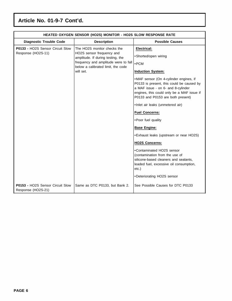
HEATED OXYGEN SENSOR (HO2S) MONITOR - HO2S SLOW RESPONSE RATE
Diagnostic Trouble Code Description Possible Causes
P0133 - HO2S Sensor Circuit Slow The HO2S monitor checks the Electrical:Response (HO2S-11) HO2S sensor frequency and
•Shorted/open wiringamplitude. If during testing, thefrequency and amplitude were to fall •PCMbelow a calibrated limit, the codewill set. Induction System:
•MAF sensor (On 4-cylinder engines, ifP0133 is present, this could be caused bya MAF issue - on 6- and 8-cylinderengines, this could only be a MAF issue ifP0133 and P0153 are both present)
• Inlet air leaks (unmetered air)
Fuel Concerns:
•Poor fuel quality
Base Engine:
•Exhaust leaks (upstream or near HO2S)
HO2S Concerns:
•Contaminated HO2S sensor(contamination from the use ofsilicone-based cleaners and sealants,leaded fuel, excessive oil consumption,etc.)
•Deteriorating HO2S sensor
P0153 - HO2S Sensor Circuit Slow Same as DTC P0133, but Bank 2. See Possible Causes for DTC P0133Response (HO2S-21)
PAGE 6

Article No. 01-9-7 Cont’d.
HEATED OXYGEN SENSOR (HO2S) MONITOR - HO2S SIGNAL CIRCUIT MALFUNCTION
Diagnostic Trouble Code Description Possible Causes
P0131 - HO2S Sensor Circuit Out The HO2S sensor is monitored for Electrical:of Range Low Voltage (HO2S-11) a negative voltage known as
•Contaminated HO2S sensor or connectorCharacteristic Shift Downward(coolant, water, silicone, fuel, oil, etc.)(CSD). If the sensor is switching
from 0 volts to -1 volts during •Chafed/damaged wiringtesting and DTC P0131 is present,the PCM will be in FMEM. •Crossed HO2S signal/signal return wiring
•PCM
P0136 - HO2S Sensor Circuit The downstream HO2S sensor(s) •Disconnected sensorMalfunction (HO2S-12) are continuously checked for
•Pinched, shorted, corroded wiring or pinsmaximum and minimum voltages.The code will set when the voltages •Crossed sensor wiresfail to meet the calibrated limits.
•Exhaust leaks
•Contaminated or damaged sensor
•Chafed/damaged wiring
P0151 - HO2S Sensor Circuit Out Same as DTC P0131, but Bank 2. See Possible Causes for DTC P0131of Range Low Voltage (HO2S-21)
P0156 - HO2S Sensor Circuit Same as DTC P0136, but Bank 2. See Possible Causes for DTC P0136Malfunction (HO2S-22)
HEATED OXYGEN SENSOR (HO2S) MONITOR - HO2S SIGNAL CIRCUIT MALFUNCTION
Diagnostic Trouble Code Description Possible Causes
P0135 - HO2S Sensor Heater During testing, the HO2S heaters •Blown fuseCircuit Malfunction (HO2S-11) are checked for opens/shorts and
•Short to VPWR in harness or HO2Sexcessive current draw. The codewill set when current draw exceeds •Water in harness connectora maximum calibrated limit or fallsbelow a minimum calibrated limit •Open VPWR or GND circuitand/or an open or short is detected.
•Low battery voltage
•Poor electrical connections from PCM toHO2S sensor
•HO2S heater
•PCM
P0141 - HO2S Sensor Heater Same as DTC P0135, but See Possible Causes for DTC P0135Circuit Malfunction (HO2S-12) downstream Bank 1.P0155 - HO2S Sensor Heater Same as DTC P0135, but Bank 2. See Possible Causes for DTC P0135Circuit Malfunction (HO2S-21)P0161 - HO2S Sensor Heater Same as DTC P0141, but See Possible Causes for DTC P0135Circuit Malfunction (HO2S-22) downstream Bank 2.
PAGE 7

Article No. 01-9-7 Cont’d.
HEATED OXYGEN SENSOR (HO2S) MONITOR - EXHAUST TEMPERATURE OUT OF RANGE, O2 SENSOR TESTNOT COMPLETED
Diagnostic Trouble Code Description Possible Causes
P1127 - Exhaust Not Warm The HEGO monitor uses an •Engine not operating long enough prior toEnough, Downstream Sensor Not exhaust temperature model to performing KOER self-testTested determine when the HO2S heaters
•Exhaust temperature not warm enoughcan safely be turned on. The codeis set when the inferred exhaust •Pre-existing P0135, P0141, P0155, P0161temperature is below a minimumcalibrated value.
HEATED OXYGEN SENSOR (HO2S) MONITOR - SWAPPED HO2S CONNECTOR
Diagnostic Trouble Code Description Possible Causes
P1128 - Upstream Oxygen Sensors The HEGO monitor checks and •Crossed HO2S harness connectors - BankSwapped from Bank 1 (HO2S-11) to determines if the HO2S signal to Bank (upstream)Bank 2 (HO2S-21) response for a KOER fuel shift
•Crossed HO2S wiring at 104-pin PCMcorresponds to the correct engineconnector or at the HO2S connectorsbank. The code is set when the
expected HO2S response is seenon the opposite bank.
P1129 - Downstream Oxygen Same as DTC P1128, but See Possible Causes for DTC P1128Sensors Swapped from Bank 1 downstream.(HO2S-12) to Bank 2 (HO2S-22)
D.) CATALYST EFFICIENCY MONITOR Some vehicles will monitor substantially less thanthe entire catalyst volume in order to meet the
D1.) Catalyst Efficiency Monitor - Information stringent catalyst monitoring malfunction thresholds.In many cases, only the front, light-off catalyst isThe Federal Test Procedure Catalyst Monitormonitored.monitors for deterioration in the catalyst system and• Front and rear HO2S switches are counted underilluminates the MIL when tailpipe emissions exceed
specified closed loop fuel conditions. After thethe appropriate HC emission thresholds. Therequired number of front switches are obtained, aCatalyst Monitor is enabled after the upstream andrear-to-front HO2S switch ratio is calculated. Thedownstream HO2S sensors have been tested andswitch ratio is compared against a thresholdverified to be functional. This monitor relies on thevalue. If the switch ratio is greater than thefront and rear heated oxygen sensors (HO2S) tocalibrated maximum limit, the catalyst has failed.infer catalyst efficiency based upon oxygen storageThe test entry conditions for the Catalystcapacity. Under normal closed loop fuel conditions,Efficiency Monitor are as follows: ECT or CHThigh efficiency catalysts have oxygen storage which(warmed engine), IAT (not at extreme ambientmakes the switching frequency of the rear HO2Stemperatures), MAF (greater than minimumquite slow compared with the frequency of the frontengine load), VSS (within vehicle speed window)HO2S. As catalyst efficiency deteriorates, its abilityand TP (at part throttle) are required.to store oxygen declines, and the rear HO2S begins
to switch more rapidly, approaching the frequency • Because an exponentially weighted movingof the front sensor. In general, as catalyst efficiency average is used for malfunction determination, updecreases, the switch ratio increases from a switch to six OBD II drive cycles may be required toratio of 0 for a low mileage catalyst to a switch ratio illuminate the MIL.of 0.8 or 0.9 for a low efficiency catalyst.
PAGE 8

Article No. 01-9-7 Cont’d.
NOTE The Catalyst Monitor DTCs can be categorized asfollows:THE CATALYST MONITOR ON SOME EARLY
OBD II VEHICLES (SOME 1994-1996 VEHICLES) • Catalyst system efficiency below threshold (BankWAS REFERRED TO AS THE “STEADY-STATE 1) - P0420CATALYST MONITOR” AS OPPOSED TO THE • Catalyst system efficiency below threshold (Bank“FTP CATALYST MONITOR” (DESCRIBED 2) - P0430ABOVE) THAT IS MOST COMMON FORVEHICLES BUILT AFTER 1996. BELOW IS A D2.) Catalyst Efficiency Monitor - DiagnosticBRIEF DESCRIPTION OF THE STEADY-STATE Trouble CodesCATALYST MONITOR:
The Steady-State Catalyst Monitor performs a 20second test during steady state rpm and loadconditions. The Monitor transfers closed loop fuelcontrol from the front to the rear O2 sensors. TheMonitor then observes the switching frequency andcompares it to a threshold frequency stored in anrpm/load table. A frequency higher than themaximum calibrated threshold indicates amalfunction.
CATALYST EFFICIENCY MONITOR
Diagnostic Trouble Code Description Possible Causes
P0420 - Catalyst System Efficiency Indicates Bank 1 catalyst system •Malfunctioning ECT/CHTBelow Threshold (Bank 1) efficiency is below the acceptable
•High fuel pressurethreshold.
•Damaged exhaust manifold
•Cylinder misfiring
•HO2S wiring concerns (shorted or chafed,bent pins, etc.)
•Damaged exhaust system pipe
•Damaged muffler/tailpipe assembly
•Retarded spark timing
Damaged Catalytic Converter:
•Use of leaded fuel
•Oil contamination/consumption
•Silicone contamination (sealants/cleaners)
P0430 - Catalyst System Efficiency Same as DTC P0420, but opposite See Possible Causes for DTC P0420Below Threshold (Bank 2) bank.
PAGE 9

Article No. 01-9-7 Cont’d.
E.) FUEL SYSTEM MONITORThe Fuel System Monitor DTCs can be categorized
E1.) Fuel System Monitor - Information as follows:
• Fuel Delivery Error - P0148The Fuel System Monitor is an on-board strategy• Lean shift in fuel system operation - P0171 (Bankdesigned to monitor the fuel trim system. The fuel
1) and P0174 (Bank 2)control system uses fuel trim tables stored in thePCM’s KAM to compensate for variability in fuel • Rich shift in fuel system operation - P0172 (Banksystem components due to normal wear and aging. 1) and P0175 (Bank 2)Fuel trim tables are based on vehicle speed and
E2.) Fuel System Monitor - Diagnostic Troubleengine load. During closed loop vehicle operation,Codesthe fuel trim strategy learns the corrections needed
to correct a “biased” rich or lean fuel system. Thecorrection is stored in the fuel trim tables. The fueltrim has two means of adapting; a LONGFT and aSHRTFT. LONGFT relies on the fuel trim tables andSHRTFT refers to the desired air/fuel ratioparameter “LAMBSE”. LAMBSE is calculated by thePCM from HO2S inputs and helps maintain a 14.7:1air/fuel ratio during closed loop operation. SHRTFTand LONGFT work together. If the HO2S indicatesthe engine is running rich, the PCM will correct therich condition by moving SHRTFT in the negativerange (less fuel to correct for a rich combustion). Ifafter a certain amount of time SHRTFT is stillcompensating for a rich condition, the PCM “learns”this and moves LONGFT into the negative range tocompensate and allows SHRTFT to return to avalue near 0%. Input from the ECT or CHT, IAT,and MAF sensors is required to activate the fueltrim system, which in turn activates the Fuel SystemMonitor. Once activated, the Fuel System Monitorlooks for the fuel trim tables to reach the adaptiveclip (adaptive limit) and LAMBSE to exceed acalibrated limit. The Fuel System Monitor will storethe appropriate DTC when a fault is detected asdescribed below.
• The HO2S detects the presence of oxygen in theexhaust and provides the PCM with feedbackindicating a rich or lean condition.
• A correction factor is added to the fuel injectorpulsewidth calculation according to the Long andShort Term Fuel Trims as needed to compensatefor variations in the fuel system.
• When deviation in the parameter LAMBSEincreases, air/fuel control suffers and emissionsincrease. When LAMBSE exceeds a calibratedlimit and the fuel trim table has clipped (reachedadaptive limit), the Fuel System Monitor sets aDTC.
• The MIL is activated after a fault is detected ontwo consecutive OBD II drive cycles.
PAGE 10

Article No. 01-9-7 Cont’d.
FUEL SYSTEM MONITOR
Diagnostic Trouble Code Description Possible Causes
P0148 - Fuel Delivery Error At least one bank lean at wide Fuel System:open throttle.
•Severely restricted fuel filter
•Severely restricted fuel supply line
P0171 - System Too Lean (Bank 1) The Adaptive Fuel Strategy Fuel System:continuously monitors fuel delivery
•Contaminated fuel injectorshardware. The code is set when theadaptive fuel tables reach a rich •Low fuel pressure or running out of fuelcalibrated limit. (fuel pump, filter, fuel supply line
restrictions)
•Vapor recovery system (VMV)
Induction System:
•MAF contamination
•Air leaks between the MAF and throttlebody
•Vacuum leaks
•PCV system concern
• Improperly seated engine oil dipstick
EGR System:
•Leaking gasket
•Stuck EGR valve
•Leaking diaphragm or EVR
Base Engine:
•Exhaust leaks before or near the HO2S
•Secondary air concern
Powertrain Control System:
•PCM concern
P0174 - System Too Lean (Bank 2) Same as DTC P0171, but Bank 2. See Possible Causes for DTC P0171
PAGE 11
Article No. 01-9-7 Cont’d.
FUEL SYSTEM MONITOR
Diagnostic Trouble Code Description Possible Causes
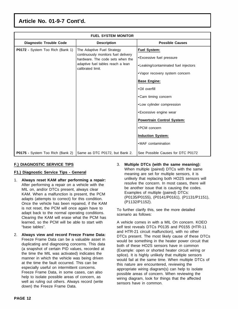
P0172 - System Too Rich (Bank 1) The Adaptive Fuel Strategy Fuel System:continuously monitors fuel delivery
•Excessive fuel pressurehardware. The code sets when theadaptive fuel tables reach a lean •Leaking/contaminated fuel injectorscalibrated limit.
•Vapor recovery system concern
Base Engine:
•Oil overfill
•Cam timing concern
•Low cylinder compression
•Excessive engine wear
Powertrain Control System:
•PCM concern
Induction System:
•MAF contamination
P0175 - System Too Rich (Bank 2) Same as DTC P0172, but Bank 2. See Possible Causes for DTC P0172
F.) DIAGNOSTIC SERVICE TIPS 3. Multiple DTCs (with the same meaning):When multiple (paired) DTCs with the same
F1.) Diagnostic Service Tips - General meaning are set for multiple sensors, it isunlikely that replacing both HO2S sensors will1. Always reset KAM after performing a repair:resolve the concern. In most cases, there willAfter performing a repair on a vehicle with thebe another issue that is causing the codes.MIL on, and/or DTCs present, always clearExamples of multiple (paired) DTCs:KAM. When a malfunction is present, the PCM(P0135/P0155), (P0141/P0161), (P1131/P1151),adapts (attempts to correct) for this condition.(P1132/P1152).Once the vehicle has been repaired, if the KAM
is not reset, the PCM will once again have to To further clarify this, see the more detailedadapt back to the normal operating conditions. scenario as follows:Clearing the KAM will erase what the PCM haslearned, so the PCM will be able to start with A vehicle comes in with a MIL On concern. KOEO“base tables”. self test reveals DTCs P0135 and P0155 (HTR-11
and HTR-21 circuit malfunction), with no other2. Always view and record Freeze Frame Data: DTCs present. The most likely cause of these DTCs
Freeze Frame Data can be a valuable asset in would be something in the heater power circuit thatduplicating and diagnosing concerns. This data both of these HO2S sensors have in common(a snapshot of certain PID values, recorded at (Example: open or shorted heater circuit wiring orthe time the MIL was activated) indicates the splice). It is highly unlikely that multiple sensorsmanner in which the vehicle was being driven would fail at the same time. When multiple DTCs ofat the time the fault occurred. This can be this nature are encountered, reviewing theespecially useful on intermittent concerns. appropriate wiring diagram(s) can help to isolateFreeze Frame Data, in some cases, can also possible areas of concern. When reviewing thehelp to isolate possible areas of concern, as wiring diagram, look for things that the affectedwell as ruling out others. Always record (write sensors have in common.down) the Freeze Frame Data.
PAGE 12

Article No. 01-9-7 Cont’d.
In this example, the most likely cause of DTCs 2. Do not compare HO2S switch rate -P0135 and P0155 (with no other DTCs present) Bank-to-Bank or vehicle-to-vehicle: Differentwould be a concern with Splice “B” (refer to Figure HO2S switch rates, from Bank-to-Bank, are2). considered normal. The HO2S switch rate, from
one Bank to the other, should not be comparedNOTE as a gauge of the HO2S’s ability toTHIS ILLUSTRATION IS ONLY AN EXAMPLE. switch/react. The PCM is continuously adjustingSPLICE NAMES “A”, “B”, AND “C” ARE USED spark and fuel in reaction to engine operatingIN THIS EXAMPLE FOR CONVENIENCE ONLY. conditions (rpm, load, air flow, throttle angle,ON AN ACTUAL VEHICLE, SPLICE NAMES WILL etc.). The PCM is also continuously adapting toDEPEND ON THE CIRCUIT NUMBER FOR THE certain conditions (customer driving habits,VEHICLE UNDER REPAIR. NOTE ALSO THAT engine and component wear, etc.).THIS FIGURE IS NOT INTENDED TO SHOW ALL
F3.) Tips Related to Catalyst Efficiency MonitorSPLICES/CONNECTIONS ON ALL VEHICLES.OTHER EEC CIRCUITS, NOT SHOWN, MAY
1. Determining catalyst efficiency/switch ratio:ALSO BE SPLICED IN WITH THE CIRCUITSThe upstream HO2S sensors will have a highSHOWN.switch frequency, due to normal closed loopfuel control. With an efficient catalyst, the4. View HO2S PID data carefully: NGS PIDs fordownstream HO2S will have a low switchHO2S sensors that do not exist (with certainfrequency. The switch ratio is determined byexhaust configurations) will show a value of “0”dividing the number of downstream switches byvolts (refer to Figures 3 and 4).the number of upstream switches over a given
In this example, the vehicle (equipped with a period of time. As the catalyst ages (or if the4-cylinder engine) has one upstream and one catalyst is damaged or contaminated), thedownstream HO2S. Notice that the NGS (scan tool) downstream switches will increase. When thedisplay shows two upstream and two downstream downstream switch rate crosses a thresholdHO2S PIDs, and that the “unused” HO2S sensor value (approximately 0.75 switch ratio), a codePIDs display “0” volts. is stored (P0420 and/or P0430) and the MIL
illuminates (refer to Figures 5 and 6).5. HO2S sensors measure oxygen in theexhaust, not fuel: The exhaust gas condition NOTEreported by the HO2S sensor is based on the IF A CATALYST IS DETERMINED TO HAVE LOWpresence of oxygen in the exhaust, not the EFFICIENCY AND REQUIRES REPLACEMENT,presence of unburned fuel. REPLACEMENT OF THE DOWNSTREAM HO2S
SENSORS WILL NOT BE NECESSARY.Example: In the event of an ignition-related misfire,you might expect a rich HO2S reading, due to the 2. Use care in handling HO2S sensors: In theamount of unburned fuel in the exhaust system. event of catalyst replacement, use care in theHowever, there is also a large amount of unburned handling of HO2S sensors to prevent damageoxygen, since no combustion took place in the or contamination. Do not use power tools in themisfiring cylinder. Since the HO2S senses oxygen removal or installation of sensors. Use a 22mmonly, it would report a lean condition in this wrench or crow foot to remove and installparticular situation. HO2S sensors; do not use slotted sockets, as
these sockets may damage wires. HO2SF2.) Tips Related to Heated Oxygen Sensorsensors should be torqued to 41 ±5 N•m (30(HO2S) Monitor±4 lb-ft).
1. OBD II Response Rate Monitor: The OBD IIResponse Rate Monitor (P0133/P0153) is onlyrun at vehicle speeds between approximately50-95 km/h (30-60 mph), during steady-stateconditions. The test lasts approximately 6seconds. Therefore, P0133/P0153 cannot bediagnosed at idle in the repair bay.
PAGE 13

Article No. 01-9-7 Cont’d.
3. Do not replace downstream HO2S sensors a. Vacuum leaks/unmetered air: In this type(HO2S12/HO2S22) for DTCs P0420 and/or of condition, the engine may actually runP0430: When diagnosing a vehicle with a lean of stoichiometry (14.7:1 air/fuel ratio) ifcustomer concern of MIL On and DTCs the PCM is not able to compensate enoughP0420/P0430 in continuous memory, do not to correct for the condition. This condition isreplace the downstream HO2S sensors typically caused by air entering the engine(HO2S12/HO2S22). Damaged or malfunctioning through an abnormal source (opening), ordownstream HO2S sensors will not cause these due to a MAF malfunction. In this situation,DTCs to be set. Always verify the vehicle the volume of air entering the engine isconcern, then perform the pinpoint diagnostics actually greater than what the MAF isin the appropriate PC/ED Service Manual. indicating to the PCM. Vacuum leaks will
normally be most apparent when highF4.) Tips Related to the Fuel System Monitor manifold vacuum is present, during idle or
light throttle. If Freeze Frame Data indicates1. HO2S sensors are not likely to be the causethat the fault occurred at idle, a check forof adaptive DTCs P0171, P0172, P0174,vacuum leaks/unmetered air when theP0175: Most warranty-returned HO2S sensorsengine is cold might be the best starting(replaced for these DTCs) are found to functionpoint.normally. Additional related DTCs will normally
be present if there is a concern with the HO2S Examples: Loose, leaking or disconnected vacuumsensors. Do not replace an HO2S sensor lines, intake manifold gaskets or O-rings, throttleunless verified through pinpoint diagnostic tests body gaskets, brake booster, air inlet tube,found in the PC/ED Service Manual. stuck/frozen/aftermarket PCV valve, unseated
engine oil dipstick, MAF reading lower than normal,2. DTCs P0171, P0172, P0174, and P0175 areetc.not related to downstream HO2S sensors:
When diagnosing a vehicle with a MIL On and b. Insufficient fueling: In this type ofDTC(s) P0171, P0172, P0174, and/or P0175 in condition, the engine may actually run leancontinuous memory, do not replace the of stoichiometry (14.7:1 air/fuel ratio) if thedownstream HO2S sensors. These DTCs have PCM is not able to compensate enough tono connection to the downstream HO2S sensor correct for the condition. This condition isfunction nor its diagnosis for faults. Always typically caused by a fuel delivery systemverify the vehicle concern, then perform the concern that restricts or limits the amount ofpinpoint diagnostics from the appropriate PC/ED fuel being delivered to the engine. ThisService Manual. condition will normally be most apparent
when the engine is under a heavy load,3. Diagnosing lean conditions and lean DTCswhen a higher volume of fuel is required. IfP0171, P0174: Freeze Frame Data can oftenFreeze Frame Data indicates that the faulthelp to identify the type of lean condition, evenoccurred under a heavy load, a check of theif the fault is intermittent, by indicating how thefuel delivery system (checking fuel pressurevehicle was being driven when the faultwith engine under a load) might be the bestoccurred. Diagnosis of lean conditions and leanstarting point.adaptive DTCs can be difficult, especially if the
concern is intermittent. Verifying the concern is Examples: Low fuel pressure (fuel pump, fuel filter,extremely important. There are different types fuel leaks, restricted fuel supply lines), fuel injectorof lean conditions. The ability to identify the concerns, etc.type of lean condition causing the concern canbe crucial to a correct diagnosis. When DTCsP0171 and P0174 are both present, there is astrong likelihood of another concern beingpresent:
PAGE 14

Article No. 01-9-7 Cont’d.
c. Exhaust system leaks: In this type of At idle, an engine requires only a small volume ofcondition, the engine may actually be fuel. Due to the fact that there is a small volume ofrunning near stoichiometry (14.7:1 air/fuel fuel needed at idle, a restriction in the fuel supplyratio), but the exhaust gas mixture will be line in many cases will not cause the fuel pressurelean. This condition is caused by to be low. When the vehicle is under a load, theoxygen-rich air entering the exhaust system engine requires much more fuel than at idle. Underthrough an external source. This condition a load, a restriction in the fuel supply line willwill cause the exhaust gas mixture to be prevent the high rate of fuel flow that is needed tolean, even though the actual combustion in maintain the correct fuel pressure.the engine may not be.
OTHER APPLICABLE ARTICLES: 98-23-10Examples: Exhaust system leaks upstream or near WARRANTY STATUS: INFORMATION ONLYHO2S, malfunctioning Secondary Air Injection OASIS CODES: 623000, 690000, 698298system.
d. MAF concerns: If a MAF concern issuspected, see TSB 98-23-10.
4. Checking fuel pressure: Check fuel pressurewith engine under a load when diagnosing alean concern. A partially plugged fuel filter canbe difficult to detect and can be easilyoverlooked if fuel pressure is only checked atidle. The same is true for other types of fuelsupply concerns (e.g., bent or kinked lines,degraded fuel pump).
Figure 1 - Article 01-9-7
PAGE 15

Article No. 01-9-7 Cont’d.
Figure 2 - Article 01-9-7
Figure 3 - Article 01-9-7 Figure 4 - Article 01-9-7
PAGE 16

Article No. 01-9-7 Cont’d.
Figure 5 - Article 01-9-7
Figure 6 - Article 01-9-7
PAGE 17


![Trouble Codes OBDII[1]](https://img.pdfslide.us/doc/110x75/577ce7731a28abf103952cd6/trouble-codes-obdii1.jpg)