Embed Size (px)
Citation preview
© Quantum3D, Inc. All rights reserved. All trademarks are property of their respective owners.
HHeeaavvyy MMeettaall™™ UUsseerr GGuuiiddee
System Operation Manual for Quantum3D Heavy Metal
Visual Computing Systems
Release 1.0 January 20, 2000
Part Number: 700-1000-01
Quantum3D, Inc.
6810 Santa Teresa Blvd San Jose CA, 95119
Telephone (408) 361-9999 Facsimile (408) 361-9980
Technical Support (408) 361-9998 http://www.quantum3d.com
Heavy Metal Installation and Operations Guide
Heavy Metal and Operations Guide Date: 1/26/00
2
Table of Contents
Table of Contents ..............................................................................................................2
1. Legal Stuff .................................................................................................................7
2. Quantum3D Visual Computing Systems ................................................................8
3. Unpacking Your Quantum3D System.....................................................................9
3.1. Inspect the Shipment .........................................................................................9 3.2. Check the Tip and Tell........................................................................................9 3.3. Check the ShockWatch....................................................................................10 3.4. Open the box.....................................................................................................10 3.5. Remove the Accessory Box.............................................................................10 3.6. Remove the computer system.........................................................................10 3.7. Open the smaller Accessory Box....................................................................11 3.8. Locate the packing list and confirm contents................................................11 3.9. Heavy Metal GX+ Contents ..............................................................................11 3.10. Heavy Metal BX Contents ................................................................................12
4. First Time Inspection .............................................................................................13
4.1. Confirm Components are Seated Properly.....................................................13 4.2. Confirm Installation of Expansion Cards .......................................................14 4.3. Confirm that the CPU and RAM is properly seated .......................................16 4.4. Confirm that the cables are attached properly to the floppy, CDROM, and hard disk........................................................................................................................17 4.5. Confirm the Bill of Materials ............................................................................17
5. Installation...............................................................................................................18
5.1. Installation of a single channel stand-alone system .....................................18 5.1.1. You will need the following items, not supplied with the system. ..................18 5.1.2. You will need the following from your Accessory Box...................................18 5.1.3. Power Requirements ....................................................................................18 5.1.4. Keyboard, Mouse, Monitor and Network Connectors ...................................18 5.1.5. Secondary Display Device and Medusa Adapter Cable ...............................19 5.1.6. Install the Mercury Swaplock Cable..............................................................21
5.2. Powering on a Single Channel, Stand-alone System ....................................21 5.2.1. Type your question here and then click SearchConfirm that RAM and CPUs are recognized.............................................................................................................22 5.2.2. Login to the system.......................................................................................22
5.3. System Shutdown Procedures........................................................................22
6. Verifying System Operation...................................................................................23
6.1. 2D Output and Windows Operation ................................................................23 6.1.1. Testing the Glide Drivers ..............................................................................23
Heavy Metal Installation and Operations Guide
Heavy Metal and Operations Guide Date: 1/26/00
3
6.1.2. Running OpenGVS Realworld Benchmarks .................................................23 6.1.3. Running the OpenGVS SDK Demos ............................................................23 6.1.4. OpenGVS Demo Help ..................................................................................24
6.2. Network Operation............................................................................................25
7. Heavy Metal Device Numbers and PCI Detection Order......................................26
7.1. PCI Device Detection Order .............................................................................26 7.2. Graphics Device Enumeration.........................................................................26 7.3. Heavy Metal BX Device Enumeration..............................................................26 7.4. Heavy Metal GX+ Device Enumeration ...........................................................27 7.5. Understanding the Device Number .................................................................28
8. Swaplock.................................................................................................................30
8.1. Overview of SwapLock.....................................................................................30 8.2. SwapLock™ Cable Connectors for Mercury ..................................................30
8.2.1. Mercury Cap Card Header Connections.......................................................30 8.2.2. Mercury Internal SwapLock Cabling .............................................................31 8.2.3. Mercury External SwapLock Cabling............................................................31 8.2.4. Configuring Multi-channel Mercury Systems ................................................32
8.3. SwapLock Connections for the 200SB and 200SBi .......................................33 8.4. SwapLock for Shared 200SB Channels ..........................................................34
8.4.1. Shared 200SB/200SBi Channels..................................................................34 8.4.2. 200SB/200SBi Distributed Channels ............................................................36
8.5. Application Startup...........................................................................................37 8.6. Application Shutdown......................................................................................37 8.7. SwapLocking Various Obsidian2 Graphics Systems ....................................37
9. Using Obsidian2 Display Properties .....................................................................38
9.1. Confirming Device Enumeration .....................................................................38 9.2. Using the Glide Test .........................................................................................39 9.3. Using the Adapter Information ........................................................................39 9.4. Using the 3D TV Settings .................................................................................40 9.5. Display Properties Settings for SwapLock.....................................................40
10. Included Software...................................................................................................42
10.1. 200SB and 200SBi 3dfx Glide Drivers.............................................................42 10.1.1. 200SB/200SBi Video Formats ......................................................................42 10.1.2. TV Output Capabilities..................................................................................42 10.1.3. 3dfx Glide 200SB/200SBi Professional Driver Files......................................42
10.2. Mercury 3dfx Glide Drivers ..............................................................................43 10.2.1. Mercury Video Timings.................................................................................45 10.2.2. Mercury TV Output Capabilities ....................................................................45 10.2.3. 3dfx Glide Mercury Driver Files.....................................................................45
10.3. Driver Software Utilities ...................................................................................45 10.3.1. GDETECT.EXE ............................................................................................46 10.3.2. GMOJO.EXE ................................................................................................46
Heavy Metal Installation and Operations Guide
Heavy Metal and Operations Guide Date: 1/26/00
4
10.3.3. DETECT.EXE...............................................................................................47 10.3.4. MOJO.EXE...................................................................................................47 10.3.5. GWHAT.EXE................................................................................................48 10.3.6. PASS.EXE....................................................................................................48 10.3.7. PCIRW.EXE..................................................................................................48 10.3.8. Q3DMTRR.EXE............................................................................................49
10.4. SimGL................................................................................................................50 10.4.1. How to get SimGL.........................................................................................50 10.4.2. Running with SimGL.....................................................................................50 10.4.3. How SimGL works on Obsidian2 Graphics...................................................50 10.4.4. Background and History ...............................................................................50 10.4.5. What is OpenGL? .........................................................................................51 10.4.6. What is SimGL?............................................................................................51 10.4.7. SimGL Use of Low level Graphics APIs........................................................51 10.4.8. Developing an Application with SimGL.........................................................52 10.4.9. OpenGL Functions available in SimGL.........................................................52 10.4.10. SimGL Extension Functions ......................................................................52 10.4.11. Conclusion.................................................................................................52
10.5. Useful Environment Variables.........................................................................52 10.5.1. SSTV2_MDETECT.......................................................................................52 10.5.2. SST_DUALHEAD.........................................................................................52 10.5.3. GV_PATH_MODELS A list of directories, separated by semi-colon (;) which tells OpenGVS where to search for external models if not found in normal model locations (as specified by the model).......................................................................................................................53 10.5.4. TXTPATH .....................................................................................................53 10.5.5. GV_ENV_SPLASH.......................................................................................53 10.5.6. GV_ENV_FBF_RESOLUTION .....................................................................53 10.5.7. GV_ENV_FBF_UNIT ....................................................................................53 10.5.8. GV_ENV_SGL_SSE.....................................................................................53 10.5.9. FX_GLIDE_NO_SPLASH.............................................................................53 10.5.10. FX_GLIDE_SHAMELESS_PLUG..............................................................53 10.5.11. FX_GLIDE_SWAPINTERVAL ...................................................................53 10.5.12. SST_INITDEBUG ......................................................................................53 10.5.13. SST_INITDEBUG_FILE.............................................................................53
10.6. OpenGVS Realworld Benchmarks ..................................................................53
11. Trouble Shooting....................................................................................................55
11.1. Power on issues ...............................................................................................55 11.1.1. System Beeps...............................................................................................55 11.1.2. No Video Signal ............................................................................................55 11.1.3. Processor(s) Not Recognized.......................................................................55 11.1.4. Processor Fails Test.....................................................................................55 11.1.5. Boot device not found...................................................................................55 11.1.6. Where to find additional information .............................................................56
11.2. Systems Operation Problems..........................................................................56 11.2.1. NMI Memory Parity Errors ............................................................................56
Heavy Metal Installation and Operations Guide
Heavy Metal and Operations Guide Date: 1/26/00
5
11.2.2. BSOD with Stack Dump................................................................................56 11.2.3. Cannot Login to Administrator Account ........................................................56 11.2.4. Problem starting some services....................................................................56 11.2.5. Cannot logon properly, hour glass never goes away....................................57 11.2.6. Where to find additional information .............................................................57
11.3. Graphics Issues................................................................................................57 11.3.1. Black Screen on 3D Device ..........................................................................57 11.3.2. Graphics Freeze on First Frame...................................................................57 11.3.3. Flashing and Tearing on the 3D Device........................................................57 11.3.4. Glide Test is Not Active ................................................................................57 11.3.5. Mutual Exclusion Error..................................................................................57 11.3.6. Where to Find Additional Information............................................................57
12. Recovering Your System .......................................................................................59
13. System Options ......................................................................................................60
13.1. Motherboards....................................................................................................60 13.1.1. Heavy Metal BX Motherboard Make and Model ...........................................60 13.1.2. Heavy Metal GX+ Motherboard Make and Model.........................................60
13.2. Primary Video Options .....................................................................................60 13.2.1. Heavy Metal BX Primary Video Options .......................................................60 13.2.2. Heavy Metal GX+ Primary Video Options.....................................................61
13.3. Realtime 3D Graphics Options ........................................................................61 13.3.1. Heavy Metal BX Realtime 3D Graphics Subsystems....................................61 13.3.2. Heavy Metal GX+ Realtime 3D Graphics Subsystems.................................62
13.4. Storage Options................................................................................................62 13.5. CD Options........................................................................................................63 13.6. Audio Options ...................................................................................................63 13.7. Operating Systems ...........................................................................................64 13.8. CPU Options......................................................................................................64 13.9. Network Options ...............................................................................................64 13.10. Memory Options ............................................................................................64 13.11. I/O Options .....................................................................................................65
13.11.1. Quantum3D GCI2 ......................................................................................65 13.11.2. High Speed Serial......................................................................................65
14. Warranty ..................................................................................................................66
14.1. General Warranty Information .........................................................................66 14.2. Warranty Service ..............................................................................................66 14.3. Quantum3D Extended Warranty Coverage.....................................................66 14.4. Quantum3D Express Warranty Coverage.......................................................66
15. Technical Support ..................................................................................................68
16. Supplement Materials.............................................................................................69
16.1. Glossary ............................................................................................................69

Heavy Metal Installation and Operations Guide
Heavy Metal and Operations Guide Date: 1/26/00
6
16.2. Functions Defined by SimGL...........................................................................75 16.3. SimGL Function Stubs .....................................................................................77
Heavy Metal Installation and Operations Guide
Heavy Metal and Operations Guide Date: 1/26/00
7
1. Legal Stuff MISCELLANEOUS. This Agreement represents the complete agreement concerning this license and may be amended only by a writing executed by both parties. If any provision of this Agreement is held to be unenforceable, such provision shall be reformed only to the extent necessary to make it enforceable. This Agreement shall be governed by California, U.S.A. law (except for conflict of law provisions). The application of the United Nations Convention on Contracts for the International Sale of Goods is expressly excluded. Quantum3D, Obsidian, Ventana, “Affordable Reality”, the Quantum3D logo, and other Quantum3D product names are trademarks, and in some jurisdictions may be registered trademarks, of Quantum3D or its affiliated companies. “3dfx Interactive”, the 3dfx Interactive logo, Voodoo Graphics, Voodoo Rush, and other 3dfx Interactive product names are trademarks, and in some jurisdictions may be registered trademarks, of 3dfx Interactive or its affiliated companies. Other trademarks are the property of their respective owners.
COPYRIGHT NOTICE. These Materials are the copyrighted works of Quantum3D, Inc. Copyright © 1999 by Quantum3D, Inc. by permission and under license from 3dfx Interactive, Inc. Copyright © 1996, 1997 by 3dfx Interactive, Inc. All rights reserved.
NO WARRANTY; NO LIABILITY FOR DAMAGES: THIS MATERIAL IS PROVIDED “AS IS” WITHOUT ANY EXPRESS OR IMPLIED WARRANTY OF ANY KIND INCLUDING WARRANTIES OF SATISFACTORY QUALITY, MERCHANTABILITY, NONINFRINGEMENT OF THIRD-PARTY INTELLECTUAL PROPERTY, OR FITNESS FOR ANY PARTICULAR PURPOSE. IN NO EVENT SHALL QUANTUM3D BE LIABLE FOR ANY DAMAGES WHATSOEVER (INCLUDING, WITHOUT LIMITATION, DIRECT OR INDIRECT DAMAGES, DAMAGES FOR LOSS OF PROFITS, BUSINESS INTERRUPTION, LOSS OF INFORMATION) ARISING OUT OF THE USE OF OR INABILITY TO USE THE MATERIALS, EVEN IF QUANTUM3D HAS BEEN ADVISED OF THE POSSIBILITY OF SUCH DAMAGES. Without limiting the generality of the foregoing, no warranty is made that the enclosed or documented software will generate computer programs with the characteristics or specifications desired by you or that the Generated Code will be error-free.
THESE DISCLAIMERS OF WARRANTY CONSTITUTE AN ESSENTIAL PART OF THIS AGREEMENT. Because some jurisdictions prohibit the exclusion or limitation of liability for damages, the above limitation may not apply to you and you may have other legal rights that vary by jurisdiction.
US GOVERNMENT RESTRICTED RIGHTS. Use, duplication or disclosure by the U.S. government is subject to restrictions set forth in subparagraphs (a) through (d) of the Commercial Computer-Restricted Rights clause at FAR 52.227-19 when applicable, or in subparagraph (c)(l)(ii) of the Rights in Technical Data and Computer Software clause at DFARS 252.227-7013, or at 252.211-7015, or to 3dfx’s standard commercial license, as applicable, and in similar clauses in the NASA FAR Supplement. Contractor or manufacturer is Quantum3D, Inc., 6810 Santa Teresa Blvd, San Jose, CA, 95119.
All trademarks herein belong to their respective owners.
Heavy Metal Installation and Operations Guide
Heavy Metal and Operations Guide Date: 1/26/00
8
2. Quantum3D Visual Computing Systems Congratulations on choosing a Quantum3D Heavy Metal Visual Computing Platform from Quantum3D, Inc. From the motherboard to the graphics subsystem, Heavy Metal GX+ and Heavy Metal BX represent the latest in PC technology. Quantum3D Obsidian2, Mercury and AAlchemy graphics systems coupled with Intel’s latest L440BX and L440GX+ motherboards, offer unsurpassed graphics bandwidth and performance. The Heavy Metal product family name is derived from the motherboard and graphics products used at its foundation. Heavy Metal GX+ Mercury and AAlchemy contain Quantum3D hardware for full scene anti-aliasing and utilize the Intel L440GX+ motherboard (GX+). Heavy Metal BX Iron utilizes the Quantum3D Obsidian2 200Sbi (Iron) and the SuperMicro P6DBS motherboard (BX Chipset). Heavy Metal systems provide scalability, use an open systems architecture, and can be easily upgraded. Heavy Metal systems offer a high degree of reliability through individual, highly integrated performance components designed by the leaders in the PC industry. Quantum3D systems can be configured as multi-channel systems using a Shared Channel or Distributed Channel architecture. Quantum3D Heavy Metal BX and GX+ are PC systems specifically designed for deployment into any environment, including the most hostile. Heavy Metal visual computing platforms can be used as stand alone visual computing platforms, or can be configured as a single multi-channel system by adding easily integrated components. Each system can be configured and upgraded with a range of cost effective, high performance RAM, media and 3D graphics options. Heavy Metal systems provide the following key system benefits.
• Industry-standard open architecture using the best in PC components • Industry-leading polygon performance that utilizes Intel Pentium III SIMD
extensions • High degree of reliability and ruggedness • Polygon transform and lighting independent of frame buffer • Independently upgradeable polygon and fill rate performance • Varying levels of image quality and fill rate performance • Additional channels do not decrease geometry or fill rate performance • Support for low level extreme performance APIs • Support for general purpose graphics APIs • Support for high level Scene Manager APIs
Heavy Metal Installation and Operations Guide
Heavy Metal and Operations Guide Date: 1/26/00
9
3. Unpacking Your Quantum3D System
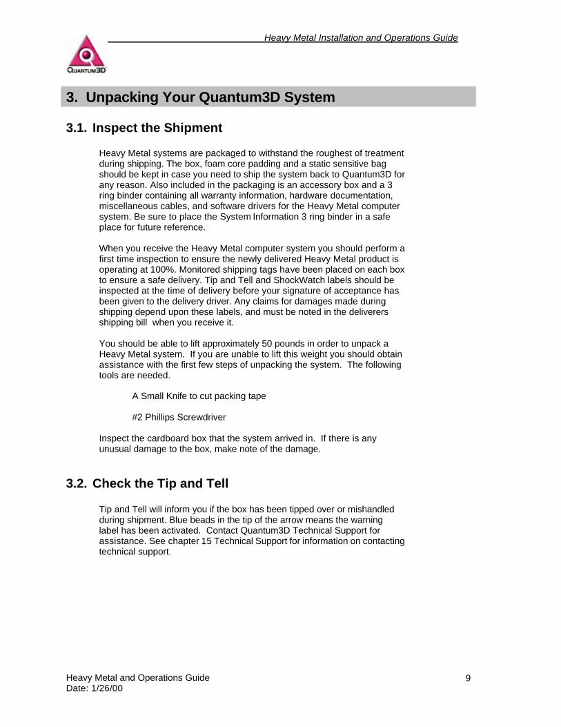
3.1. Inspect the Shipment Heavy Metal systems are packaged to withstand the roughest of treatment during shipping. The box, foam core padding and a static sensitive bag should be kept in case you need to ship the system back to Quantum3D for any reason. Also included in the packaging is an accessory box and a 3 ring binder containing all warranty information, hardware documentation, miscellaneous cables, and software drivers for the Heavy Metal computer system. Be sure to place the System Information 3 ring binder in a safe place for future reference. When you receive the Heavy Metal computer system you should perform a first time inspection to ensure the newly delivered Heavy Metal product is operating at 100%. Monitored shipping tags have been placed on each box to ensure a safe delivery. Tip and Tell and ShockWatch labels should be inspected at the time of delivery before your signature of acceptance has been given to the delivery driver. Any claims for damages made during shipping depend upon these labels, and must be noted in the deliverers shipping bill when you receive it. You should be able to lift approximately 50 pounds in order to unpack a Heavy Metal system. If you are unable to lift this weight you should obtain assistance with the first few steps of unpacking the system. The following tools are needed.
A Small Knife to cut packing tape #2 Phillips Screwdriver
Inspect the cardboard box that the system arrived in. If there is any unusual damage to the box, make note of the damage.
3.2. Check the Tip and Tell Tip and Tell will inform you if the box has been tipped over or mishandled during shipment. Blue beads in the tip of the arrow means the warning label has been activated. Contact Quantum3D Technical Support for assistance. See chapter 15 Technical Support for information on contacting technical support.
Heavy Metal Installation and Operations Guide
Heavy Metal and Operations Guide Date: 1/26/00
10
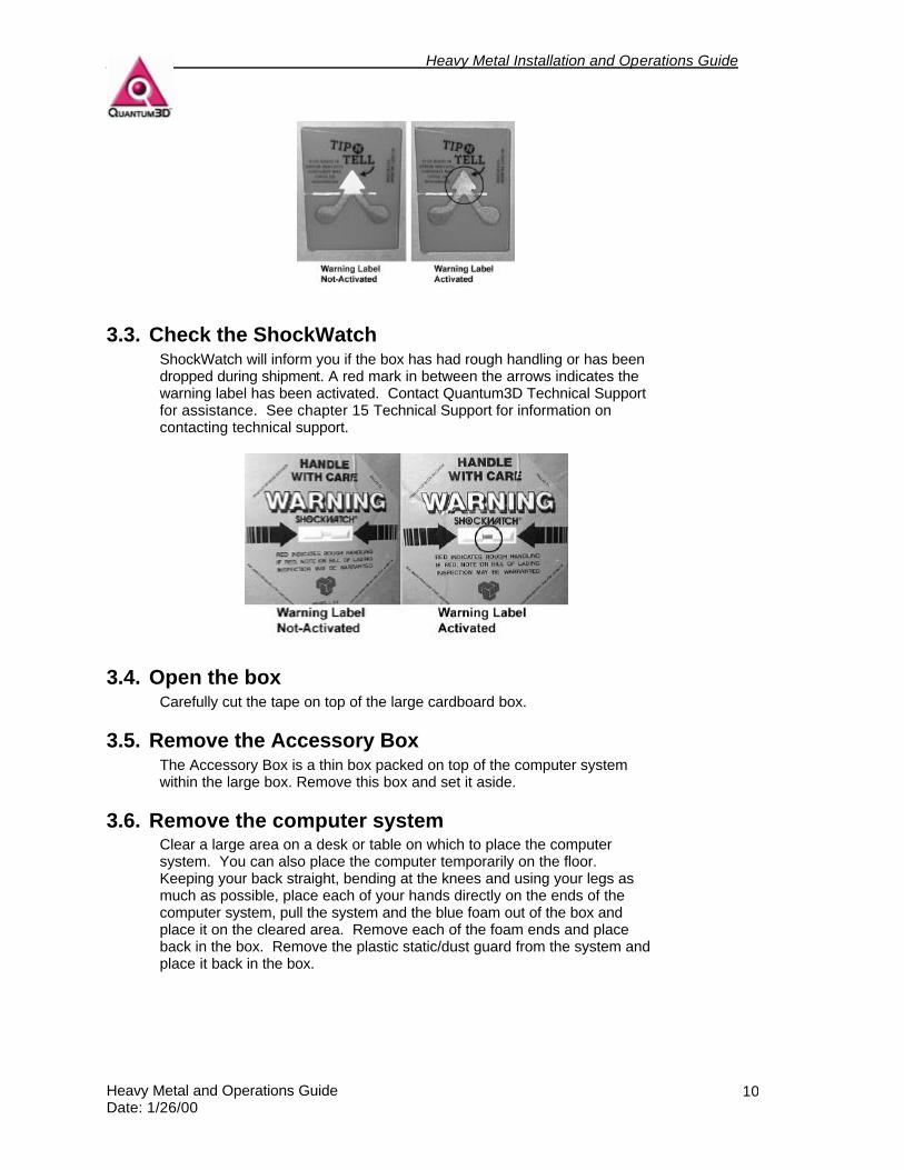
3.3. Check the ShockWatch ShockWatch will inform you if the box has had rough handling or has been dropped during shipment. A red mark in between the arrows indicates the warning label has been activated. Contact Quantum3D Technical Support for assistance. See chapter 15 Technical Support for information on contacting technical support.
3.4. Open the box Carefully cut the tape on top of the large cardboard box.
3.5. Remove the Accessory Box The Accessory Box is a thin box packed on top of the computer system within the large box. Remove this box and set it aside.
3.6. Remove the computer system Clear a large area on a desk or table on which to place the computer system. You can also place the computer temporarily on the floor. Keeping your back straight, bending at the knees and using your legs as much as possible, place each of your hands directly on the ends of the computer system, pull the system and the blue foam out of the box and place it on the cleared area. Remove each of the foam ends and place back in the box. Remove the plastic static/dust guard from the system and place it back in the box.
Heavy Metal Installation and Operations Guide
Heavy Metal and Operations Guide Date: 1/26/00
11
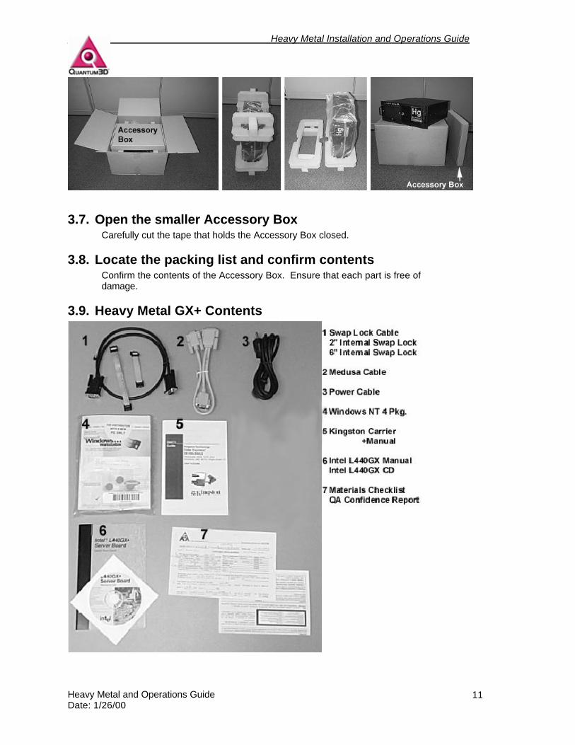
3.7. Open the smaller Accessory Box Carefully cut the tape that holds the Accessory Box closed.
3.8. Locate the packing list and confirm contents Confirm the contents of the Accessory Box. Ensure that each part is free of damage.
3.9. Heavy Metal GX+ Contents
Heavy Metal Installation and Operations Guide
Heavy Metal and Operations Guide Date: 1/26/00
12
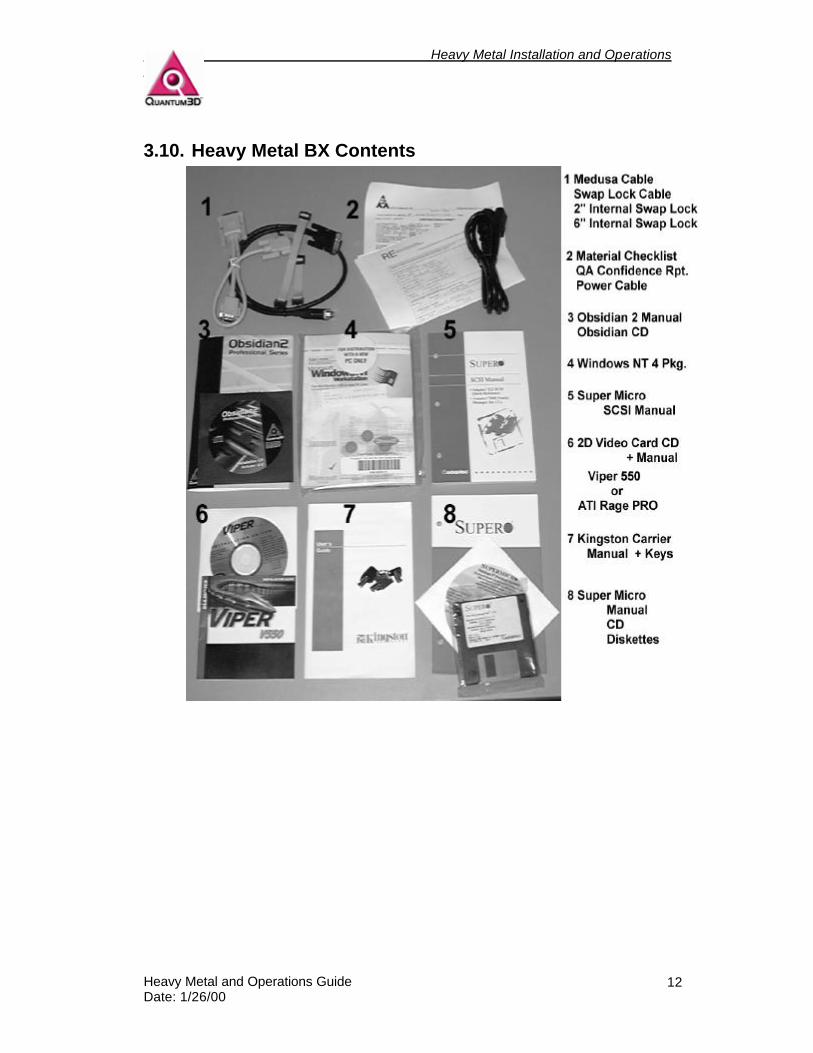
3.10. Heavy Metal BX Contents
Heavy Metal Installation and Operations Guide
Heavy Metal and Operations Guide Date: 1/26/00
13
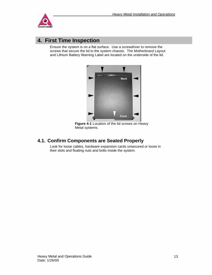
4. First Time Inspection Ensure the system is on a flat surface. Use a screwdriver to remove the screws that secure the lid to the system chassis. The Motherboard Layout and Lithium Battery Warning Label are located on the underside of the lid.
Figure 4-1 Location of the lid screws on Heavy Metal systems.
4.1. Confirm Components are Seated Properly Look for loose cables, hardware expansion cards unsecured or loose in their slots and floating nuts and bolts inside the system.
Heavy Metal Installation and Operations Guide
Heavy Metal and Operations Guide Date: 1/26/00
14
CPUs RAM
Power Supply
PCI Bus Slots
ISA Bus Slot
SCSI Cable
Drive Bay
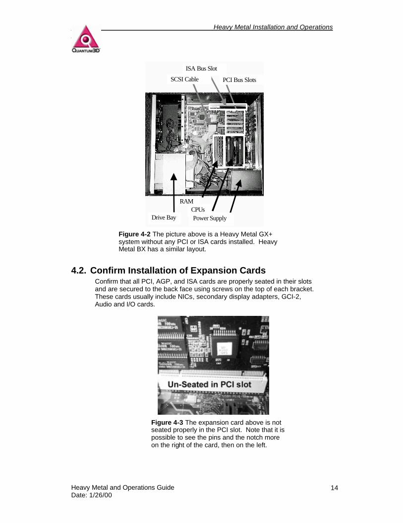
Figure 4-2 The picture above is a Heavy Metal GX+ system without any PCI or ISA cards installed. Heavy Metal BX has a similar layout.
4.2. Confirm Installation of Expansion Cards Confirm that all PCI, AGP, and ISA cards are properly seated in their slots and are secured to the back face using screws on the top of each bracket. These cards usually include NICs, secondary display adapters, GCI-2, Audio and I/O cards.
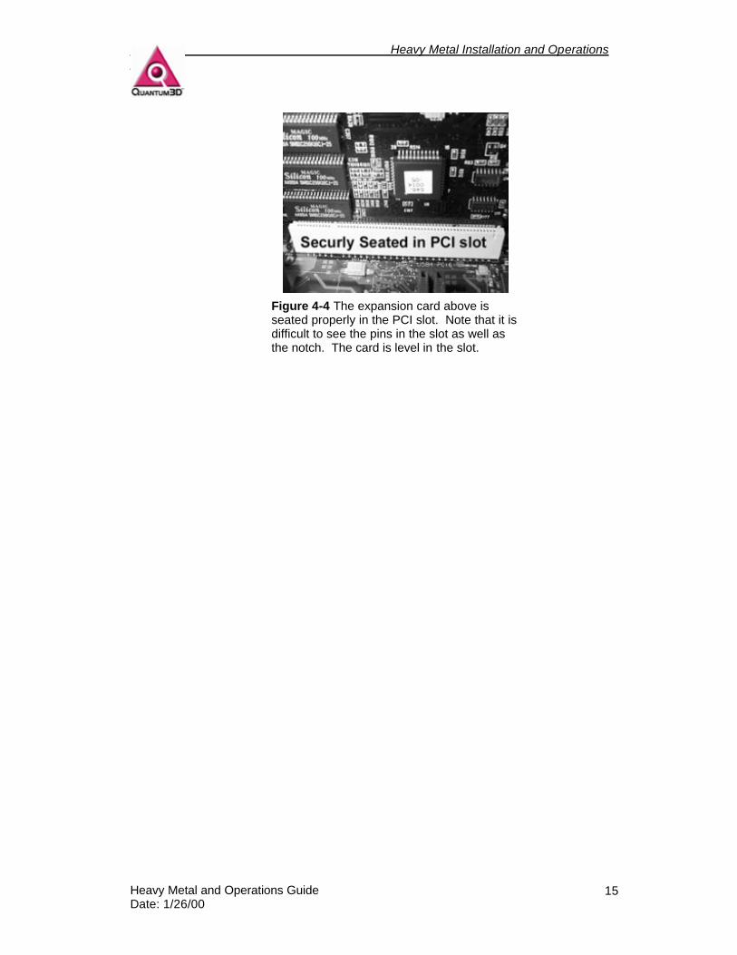
Figure 4-3 The expansion card above is not seated properly in the PCI slot. Note that it is possible to see the pins and the notch more on the right of the card, then on the left.
Heavy Metal Installation and Operations Guide
Heavy Metal and Operations Guide Date: 1/26/00
15
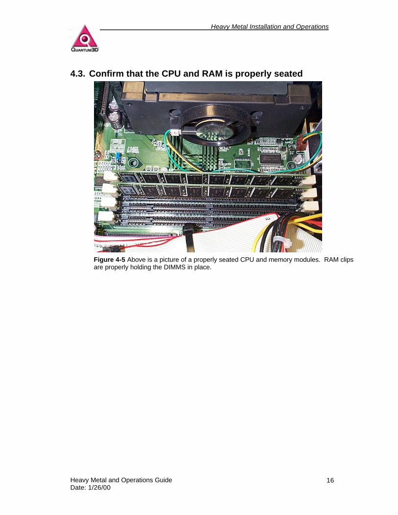
Figure 4-4 The expansion card above is seated properly in the PCI slot. Note that it is difficult to see the pins in the slot as well as the notch. The card is level in the slot.
Heavy Metal Installation and Operations Guide
Heavy Metal and Operations Guide Date: 1/26/00
16
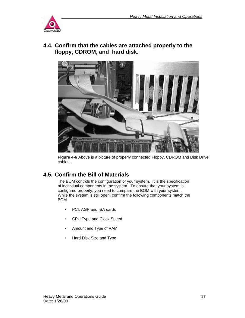
4.3. Confirm that the CPU and RAM is properly seated
Figure 4-5 Above is a picture of a properly seated CPU and memory modules. RAM clips are properly holding the DIMMS in place.
Heavy Metal Installation and Operations Guide
Heavy Metal and Operations Guide Date: 1/26/00
17
4.4. Confirm that the cables are attached properly to the floppy, CDROM, and hard disk.
Figure 4-6 Above is a picture of properly connected Floppy, CDROM and Disk Drive cables.
4.5. Confirm the Bill of Materials The BOM controls the configuration of your system. It is the specification of individual components in the system. To ensure that your system is configured properly, you need to compare the BOM with your system. While the system is still open, confirm the following components match the BOM.
• PCI, AGP and ISA cards
• CPU Type and Clock Speed
• Amount and Type of RAM
• Hard Disk Size and Type
Heavy Metal Installation and Operations Guide
Heavy Metal and Operations Guide Date: 1/26/00
18
5. Installation
5.1. Installation of a single channel stand-alone system
5.1.1. You will need the following items, not supplied with the system. 1-Multisync monitor capable of at least 1024x768@60 Hz operation for the 3D Display. Projection systems, HMDs, and large screen monitors are also commonly used as 3D display devices. If you have specific questions about compatibility, please contact Quantum3D Technical Support. (1) Multisync monitor capable of at least 1024x768@60 Hz operation for the primary Windows Display. You may wish to have a high resolution display if you are using any software that utilizes a GUI for its operation. (2) 15 Pin Video/Monitor Cables (Transducers are highly recommended). (1) CAT5 Network Cable and Operating network connection.
5.1.2. You will need the following from your Accessory Box 25 Pin to 15 Pin Medusa Cable (T-style monitor adapter) 18” Black External SwapLock™ Cable
Keyboard (Optional) Mouse (Optional) Power Cord
5.1.3. Power Requirements The systems are equipped with auto sensing power supplies that handle electricity in the ranges 120-240VAC 50-60Hz. We recommend that rack mount systems have a dedicated 20amp circuit with a clean current for proper operation.
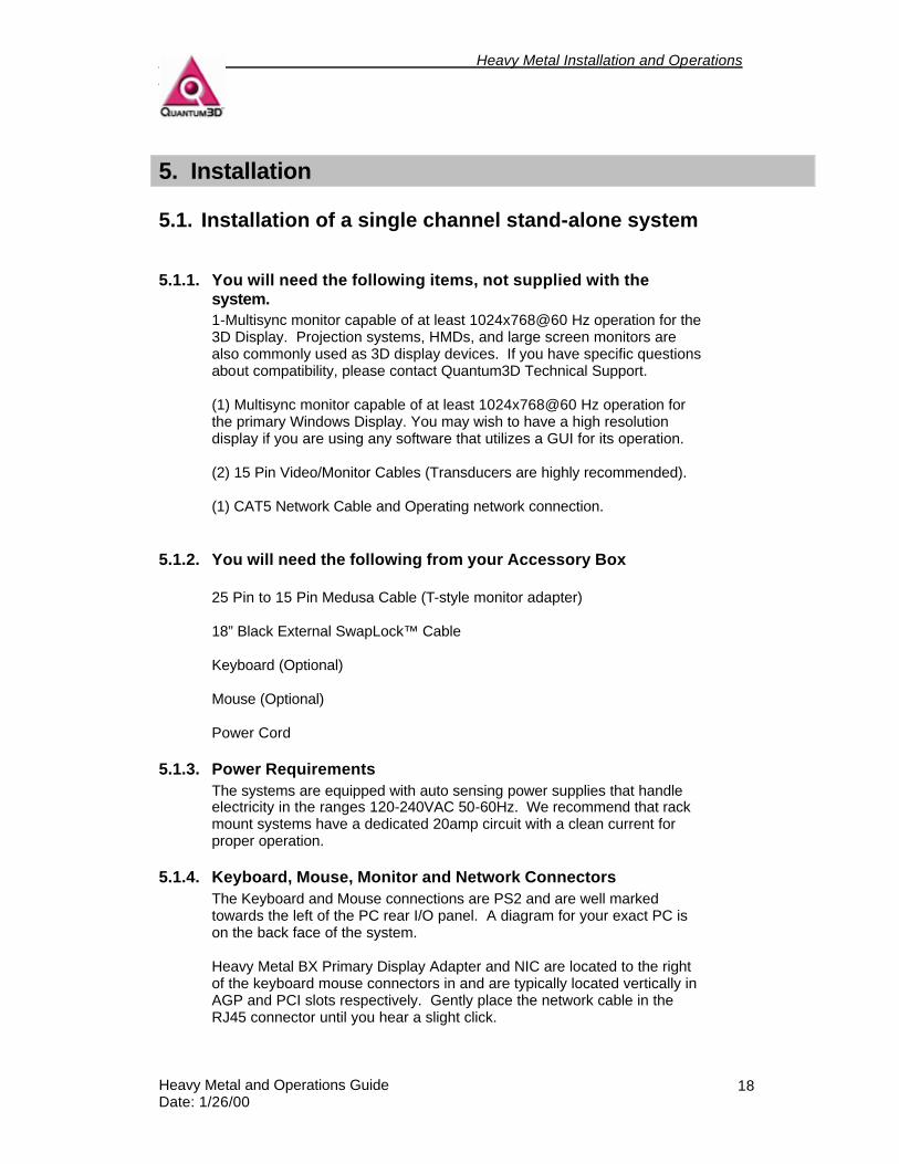
5.1.4. Keyboard, Mouse, Monitor and Network Connectors The Keyboard and Mouse connections are PS2 and are well marked towards the left of the PC rear I/O panel. A diagram for your exact PC is on the back face of the system. Heavy Metal BX Primary Display Adapter and NIC are located to the right of the keyboard mouse connectors in and are typically located vertically in AGP and PCI slots respectively. Gently place the network cable in the RJ45 connector until you hear a slight click.
Heavy Metal Installation and Operations Guide
Heavy Metal and Operations Guide Date: 1/26/00
19
Figure 5-1The GX+ motherboard. GX+ systems have the Primary Display Adapter and NIC built as an integral piece of the L440GX+ motherboard. Items labeled I and E are in different locations on Heavy Metal BX
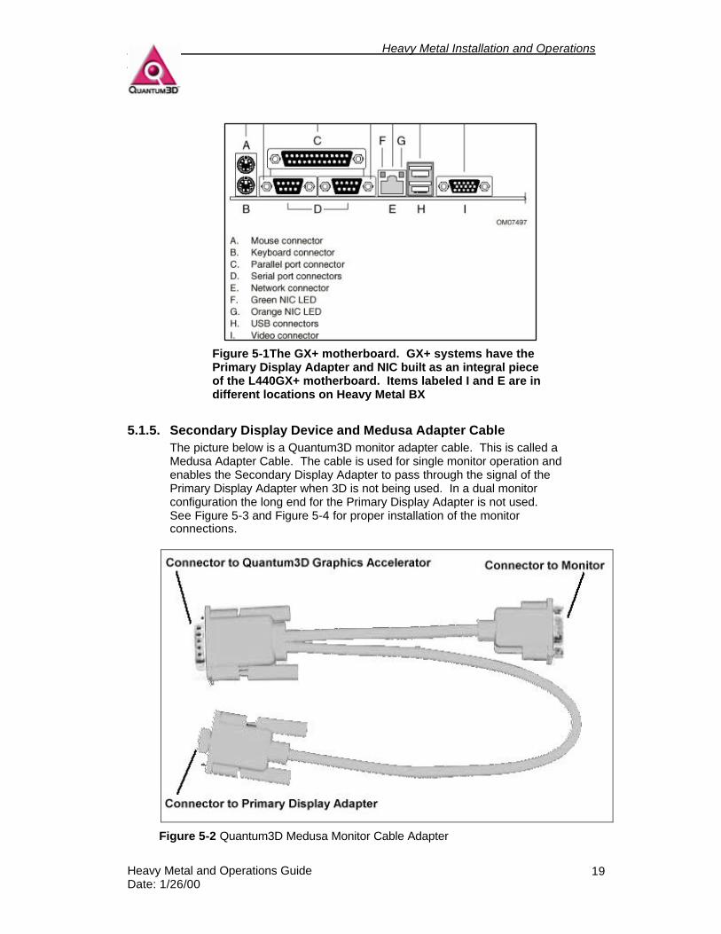
5.1.5. Secondary Display Device and Medusa Adapter Cable The picture below is a Quantum3D monitor adapter cable. This is called a Medusa Adapter Cable. The cable is used for single monitor operation and enables the Secondary Display Adapter to pass through the signal of the Primary Display Adapter when 3D is not being used. In a dual monitor configuration the long end for the Primary Display Adapter is not used. See Figure 5-3 and Figure 5-4 for proper installation of the monitor connections.
Figure 5-2 Quantum3D Medusa Monitor Cable Adapter
Heavy Metal Installation and Operations Guide
Heavy Metal and Operations Guide Date: 1/26/00
20
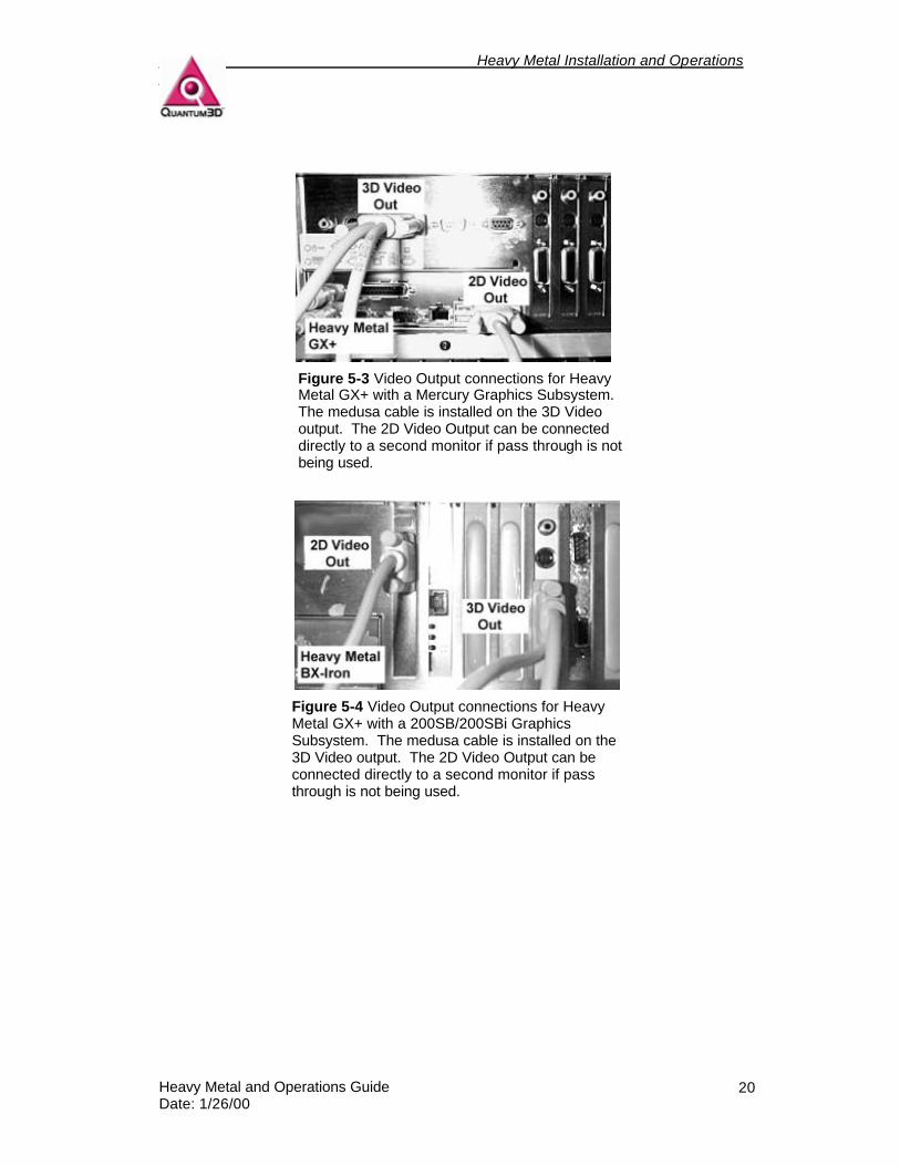
Figure 5-3 Video Output connections for Heavy Metal GX+ with a Mercury Graphics Subsystem. The medusa cable is installed on the 3D Video output. The 2D Video Output can be connected directly to a second monitor if pass through is not being used.
Figure 5-4 Video Output connections for Heavy Metal GX+ with a 200SB/200SBi Graphics Subsystem. The medusa cable is installed on the 3D Video output. The 2D Video Output can be connected directly to a second monitor if pass through is not being used.
Heavy Metal Installation and Operations Guide
Heavy Metal and Operations Guide Date: 1/26/00
21
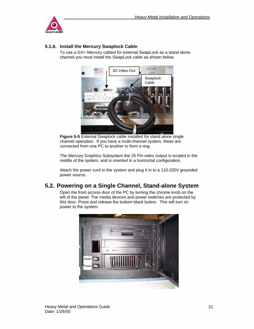
5.1.6. Install the Mercury Swaplock Cable To use a GX+ Mercury cabled for external SwapLock as a stand alone channel you must install the SwapLock cable as shown below.
Figure 5-5 External Swaplock cable installed for stand alone single channel operation. If you have a multi-channel system, these are connected from one PC to another to form a ring. The Mercury Graphics Subsystem the 25 Pin video output is located in the middle of the system, and is oriented in a horizontal configuration. Attach the power cord to the system and plug it in to a 110-220V grounded power source.
5.2. Powering on a Single Channel, Stand-alone System Open the front access door of the PC by turning the chrome knob on the left of the panel. The media devices and power switches are protected by this door. Press and release the bottom black button. This will turn on power to the system.
Swaplock Cable
3D Video Out
Heavy Metal Installation and Operations Guide
Heavy Metal and Operations Guide Date: 1/26/00
22
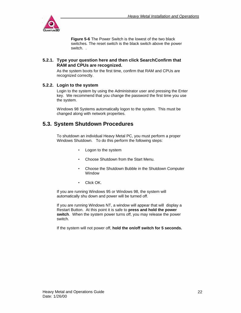
Figure 5-6 The Power Switch is the lowest of the two black switches. The reset switch is the black switch above the power switch. .
5.2.1. Type your question here and then click SearchConfirm that RAM and CPUs are recognized. As the system boots for the first time, confirm that RAM and CPUs are recognized correctly.
5.2.2. Login to the system Login to the system by using the Administrator user and pressing the Enter key. We recommend that you change the password the first time you use the system. Windows 98 Systems automatically logon to the system. This must be changed along with network properties.
5.3. System Shutdown Procedures To shutdown an individual Heavy Metal PC, you must perform a proper Windows Shutdown. To do this perform the following steps:
• Logon to the system
• Choose Shutdown from the Start Menu.
• Choose the Shutdown Bubble in the Shutdown Computer Window
• Click OK.
If you are running Windows 95 or Windows 98, the system will automatically shu down and power will be turned off. If you are running Windows NT, a window will appear that will display a Restart Button. At this point it is safe to press and hold the power switch. When the system power turns off, you may release the power switch. If the system will not power off, hold the on/off switch for 5 seconds.
Heavy Metal Installation and Operations Guide
Heavy Metal and Operations Guide Date: 1/26/00
23
6. Verifying System Operation
6.1. 2D Output and Windows Operation During power on the system will complete the boot process, Windows Startup Screen and Logon window. This is confirmation that power on has been successful. You can now try to logon to the system. If everything is operating well proceed to test 3D video output. The system will be delivered without an administrator password. If you are unable to logon, you must confirm that all devices are connected properly. If you are still unable to logon, if there is no keyboard, mouse, or video output then you should contact Quantum3D Technical Support. Quantum3D Obsidian2 or Mercury 3D Output
6.1.1. Testing the Glide Drivers After you logon to the system, use the Obsidian2 Display Properties and Click the Test Button in the Glide Area of the Window. The device to which the Medusa Cable is connected should sync to the signal and the Quantum3D Logo Test Pattern should appear on the 3D Output device. You can change the resolution and refresh rate to determine if the card, drivers, and monitor are functioning properly.
6.1.2. Running OpenGVS Realworld Benchmarks For additional confirmation that the system is operating properly, use the OpenGVS Realworld Benchmarks. OpenGVS Realworld Benchmark Demonstrations are found in the following menu:
StartMenu/Programs/OpenGVS RWB 2.3/Glide3/Demo/1024x768 All of the demonstrations under the above menu should operate as expected. Use F1 for help in using these demonstrations.
6.1.3. Running the OpenGVS SDK Demos If you have a license for the OpenGVS SDK, the software will be installed in c:\gem. If you wish to run the sample demonstration applications, they may be found in the following menu: StartMenu/Programs/OpenGVS SDK V4.3/Glide 3 Demos Any of the shortcuts that are located in the above menu and that that are accompanied by text that designates them as a multi-channel demo (i.e. Fly Comanche (Center Channel), should be run on multi-channel systems only. If you run the center channel application on a stand alone system it will operate, but will be sending channel synchronization messages over the network.
Heavy Metal Installation and Operations Guide
Heavy Metal and Operations Guide Date: 1/26/00
24
6.1.4. OpenGVS Demo Help Use F1 for help in these demonstrations. The following keys are excellent examples of Quantum3D Heavy Metal BX and GX performance and image quality. Below are summaries of some of the most valuable control keys that are shared between all demo applications. F1 Help Display the help screen over the 3D Output TAB Toggle Frame Rate Statistics Display the Frame Rate in the upper left of the window F3 Toggle More Detailed Statistics Display the number of polygons, objects, fill rate and other vital
information. This can help locate performance issues like a high ratio of culled objects to examined object ratios.
F4 Reset to Initial States and Position F5 Toggle Mercury Anti-aliasing
Toggle AA on and off with no performance change. F7 Toggle Wireframe Turn solid fill on/off. Useful for viewing where individual polygons are. F8 Pause Pause Autopilot F9 Toggle Texture Mapping Toggle textures on/off. Useful to see how unrealistic scenes are without
textures. F11 Texture Minification Toggle between point samples, Mipmapped Bilinear and Mipmapped
trilinear. These forms of texture minification filters are used to anti-alias textures. To turn off all AA first turn off Mercury AA with F5 then use F11 to change to point sampling. All AA is free with Mercury.
F12 Screen Capture Capture the 3D view to a snapXX.tif file in the local directory. a/A Toggle Autopilot Toggle between mouse fly and auto pilot fly. ,/< Autopilot Playback Speed Decrease/Increase Playback speed of autopilot. c/C Change Camera Cycle through predefined cameras l/L Sun Direction Decrease/Increase the sun elevation angle t/T Time of Day cycle through predefined time of day settings f/F Fog Thickness Decrease/increase fog thickness
Heavy Metal Installation and Operations Guide
Heavy Metal and Operations Guide Date: 1/26/00
25
o/O Record Ownship Position & Rotation Toggle Start and Stop Recording the Ownship
6.2. Network Operation See paragraph 5.1.4 for details on connecting the network cable. A green light will blink on the network adapter if the connector is operating. You will need the following information in order to connect to your LAN:
• IP address or DHCP Server Name • Network mask • Default gateway • Domain or workgroup • Domain suffix search order
All of the above parameters can be specified in the Network Control Panel found under the Start Menu/Settings/Control Panels/Network. Alternatively use Right Mouse on the Network Neighborhood Icon and Choose Properties. The new Network Properties are set after you reboot. Computers on the network are represented as Icons when you double-click on the Network Neighborhood icon.
Heavy Metal Installation and Operations Guide
Heavy Metal and Operations Guide Date: 1/26/00
26
7. Heavy Metal Device Numbers and PCI Detection Order
Heavy Metal systems have controls in the Bios Setup that determine the order in which devices are accessed on the PCI bus. The BIOS detection order is displayed in the Obsidian2 Display Properties as the device priority number. This device number is important for the proper monitor connections and Swaplock connections.
7.1. PCI Device Detection Order The PCI bus detection order is defined by the Bios and usually starts with PCI slot 0 closest to the AGP slot and ends with PCI Slot 3 closest to the ISA connectors. The PCI bus detection order is directly related to the Obsidian 2 device priority number.
7.2. Graphics Device Enumeration The Device Enumeration determines the Device number that is displayed in the Obsidian2 Display Properties. Device numbers are assigned by the display drivers starting with the default device [0] and incrementing by one as devices are detected in the PCI slots.
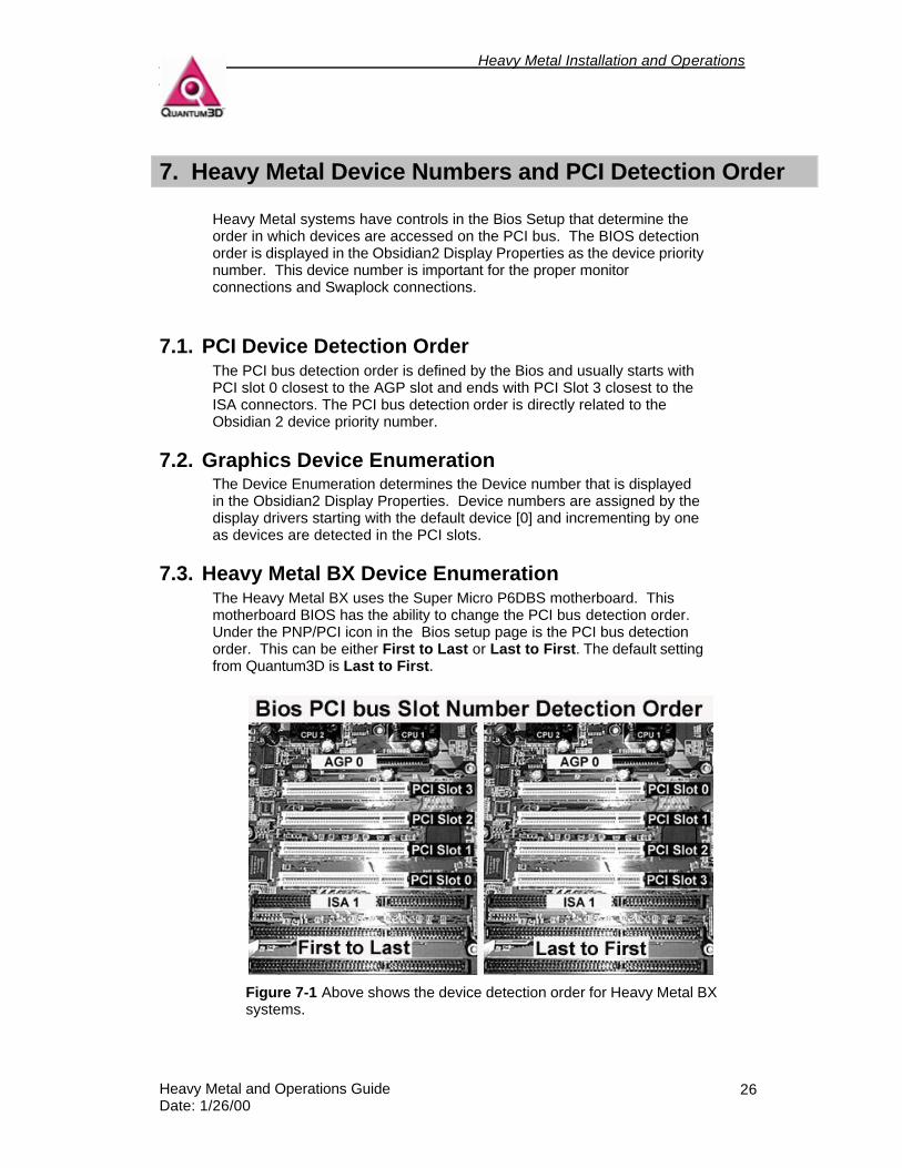
7.3. Heavy Metal BX Device Enumeration The Heavy Metal BX uses the Super Micro P6DBS motherboard. This motherboard BIOS has the ability to change the PCI bus detection order. Under the PNP/PCI icon in the Bios setup page is the PCI bus detection order. This can be either First to Last or Last to First. The default setting from Quantum3D is Last to First.
Figure 7-1 Above shows the device detection order for Heavy Metal BX systems.
Heavy Metal Installation and Operations Guide
Heavy Metal and Operations Guide Date: 1/26/00
27
7.4. Heavy Metal GX+ Device Enumeration
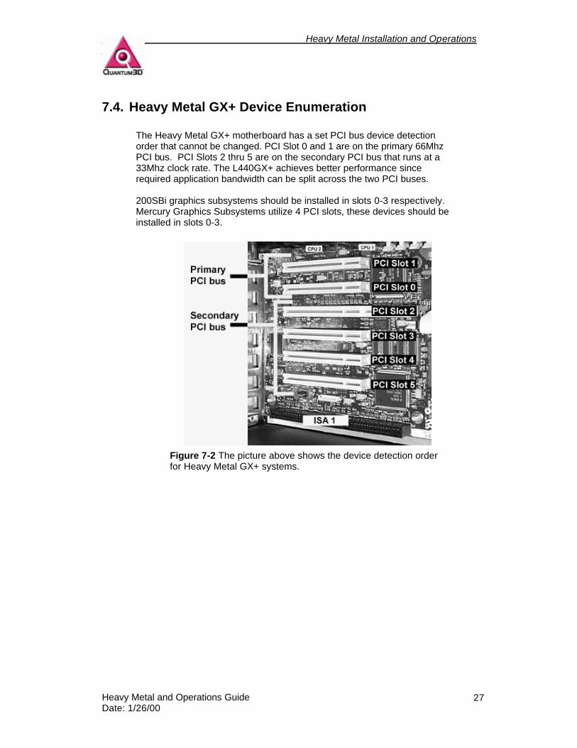
The Heavy Metal GX+ motherboard has a set PCI bus device detection order that cannot be changed. PCI Slot 0 and 1 are on the primary 66Mhz PCI bus. PCI Slots 2 thru 5 are on the secondary PCI bus that runs at a 33Mhz clock rate. The L440GX+ achieves better performance since required application bandwidth can be split across the two PCI buses. 200SBi graphics subsystems should be installed in slots 0-3 respectively. Mercury Graphics Subsystems utilize 4 PCI slots, these devices should be installed in slots 0-3.
Figure 7-2 The picture above shows the device detection order for Heavy Metal GX+ systems.
Heavy Metal Installation and Operations Guide
Heavy Metal and Operations Guide Date: 1/26/00
28
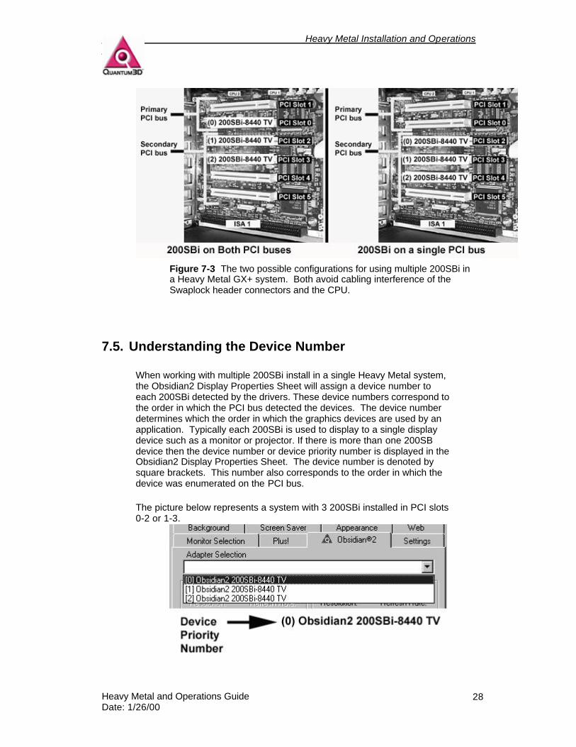
Figure 7-3 The two possible configurations for using multiple 200SBi in a Heavy Metal GX+ system. Both avoid cabling interference of the Swaplock header connectors and the CPU.
7.5. Understanding the Device Number
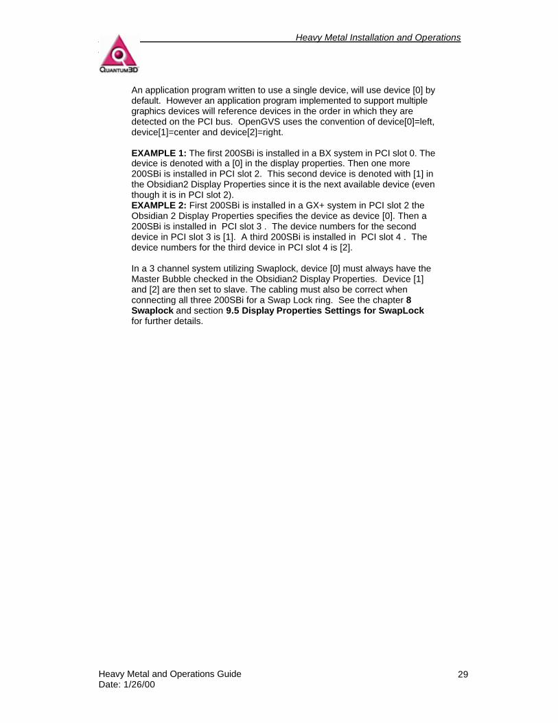
When working with multiple 200SBi install in a single Heavy Metal system, the Obsidian2 Display Properties Sheet will assign a device number to each 200SBi detected by the drivers. These device numbers correspond to the order in which the PCI bus detected the devices. The device number determines which the order in which the graphics devices are used by an application. Typically each 200SBi is used to display to a single display device such as a monitor or projector. If there is more than one 200SB device then the device number or device priority number is displayed in the Obsidian2 Display Properties Sheet. The device number is denoted by square brackets. This number also corresponds to the order in which the device was enumerated on the PCI bus.
The picture below represents a system with 3 200SBi installed in PCI slots 0-2 or 1-3.
Heavy Metal Installation and Operations Guide
Heavy Metal and Operations Guide Date: 1/26/00
29
An application program written to use a single device, will use device [0] by default. However an application program implemented to support multiple graphics devices will reference devices in the order in which they are detected on the PCI bus. OpenGVS uses the convention of device[0]=left, device[1]=center and device[2]=right. EXAMPLE 1: The first 200SBi is installed in a BX system in PCI slot 0. The device is denoted with a [0] in the display properties. Then one more 200SBi is installed in PCI slot 2. This second device is denoted with [1] in the Obsidian2 Display Properties since it is the next available device (even though it is in PCI slot 2). EXAMPLE 2: First 200SBi is installed in a GX+ system in PCI slot 2 the Obsidian 2 Display Properties specifies the device as device [0]. Then a 200SBi is installed in PCI slot 3 . The device numbers for the second device in PCI slot 3 is [1]. A third 200SBi is installed in PCI slot 4 . The device numbers for the third device in PCI slot 4 is [2]. In a 3 channel system utilizing Swaplock, device [0] must always have the Master Bubble checked in the Obsidian2 Display Properties. Device [1] and [2] are then set to slave. The cabling must also be correct when connecting all three 200SBi for a Swap Lock ring. See the chapter 8 Swaplock and section 9.5 Display Properties Settings for SwapLock for further details.
Heavy Metal Installation and Operations Guide
Heavy Metal and Operations Guide Date: 1/26/00
30
8. Swaplock
8.1. Overview of SwapLock The SwapLock feature synchronizes the low level 3dfx Glide function grBufferSwap vertical retrace across multiple 200SB or Mercury systems. This eliminates artifacts associated with lack of hardware vertical retrace syncronization. SwapLock syncronizes the buffer swap operation associated with double and triple buffered graphics systems such as the 200SB, 200SBi and Mercury. One channel (Obsidian2 Secondary Display Device) is designated as Master and initiates the synchronization signals. This can be done using the Obsidian2 Display Properties. The master is always Device [0] in Display Properties and there is never more than one master in a SwapLock ring. Synchronization signals are carried from the Master card to Slave cards via cables. Both internal ribbon cables and external 9-Pin male to female cables can be used. These cables are specifically manufactured for Quantum3D systems. The Master and Slave devices are connected in a “ring” so that each slave in turn passes on the synchronization signals to those “downstream”, until finally the signals are once again connected back to the Master.
8.2. SwapLock™ Cable Connectors for Mercury
8.2.1. Mercury Cap Card Header Connections There are 2-10 Pin headers located on the device that are used for SwapLock. Mercury SwapLock headers are labeled identical to the 200SB and 200SBi. J23A is the input and J23B is the output. The output connector J23B is located closest to the CPU and is labeled with a 1.

Heavy Metal Installation and Operations Guide
Heavy Metal and Operations Guide Date: 1/26/00
31
8.2.2. Mercury Internal SwapLock Cabling For single channel operation Heavy Metal GX+ must have a SwapLock cable installed. This can be done using an internal loopback ribbon cable as shown below. Damage may occur if these are not properly connected.
8.2.3. Mercury External SwapLock Cabling For single channel operation and for easy integration into a Multi-channel system Heavy Metal GX+ can be cabled to use external 9 pin cables. To do this the J23A and J23B are connected to the male and female connectors as shown in the pictures below.
Heavy Metal Installation and Operations Guide
Heavy Metal and Operations Guide Date: 1/26/00
32
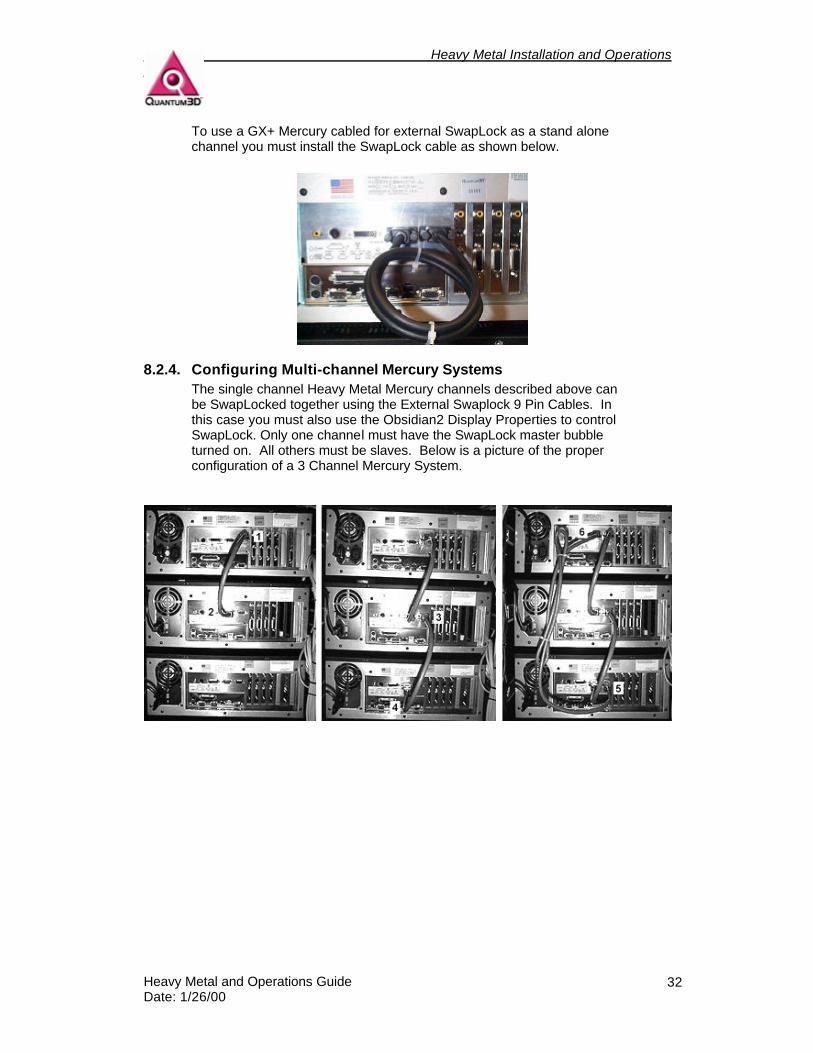
To use a GX+ Mercury cabled for external SwapLock as a stand alone channel you must install the SwapLock cable as shown below.
8.2.4. Configuring Multi-channel Mercury Systems The single channel Heavy Metal Mercury channels described above can be SwapLocked together using the External Swaplock 9 Pin Cables. In this case you must also use the Obsidian2 Display Properties to control SwapLock. Only one channel must have the SwapLock master bubble turned on. All others must be slaves. Below is a picture of the proper configuration of a 3 Channel Mercury System.
Heavy Metal Installation and Operations Guide
Heavy Metal and Operations Guide Date: 1/26/00
33
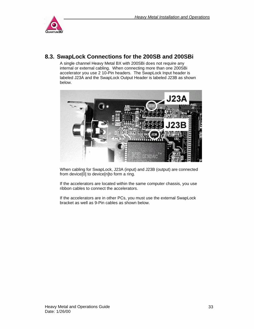
8.3. SwapLock Connections for the 200SB and 200SBi A single channel Heavy Metal BX with 200SBi does not require any internal or external cabling. When connecting more than one 200SBi accelerator you use 2 10-Pin headers. The SwapLock Input header is labeled J23A and the SwapLock Output Header is labeled J23B as shown below.
When cabling for SwapLock, J23A (input) and J23B (output) are connected from device[0] to device[n]to form a ring. If the accelerators are located within the same computer chassis, you use ribbon cables to connect the accelerators. If the accelerators are in other PCs, you must use the external SwapLock bracket as well as 9-Pin cables as shown below.

Heavy Metal Installation and Operations Guide
Heavy Metal and Operations Guide Date: 1/26/00
34
The picture below shows the external view of the Swaplock Bracket and on the left and the 9-Pin cables installed on the right. The male and female 9-Pin cable connector are connected to J23A and J23B on the 200SBi (respectively). They may be connected to a single 200SB or incorporated into a larger SwapLock ring as discussed below.
NOTE: When connecting ribbon cables to the SwapLock headers it is important to align Pin1 of the cable with Pin 1 of the header. Pin 1 of these connectors is located on the bottom of the header towards the bulk head bracket and video output. The red stripe on the ribbon cable identifies pin 1 as does an arrow on the ribbon cable connector.
8.4. SwapLock for Shared 200SB Channels
8.4.1. Shared 200SB/200SBi Channels For Heavy Metal systems with more than one Obsidian2 200SB device, the internal ribbon cables are fitted such that J23B on Device 0 is connected to the J23A of Device 1. This cabling scheme is then replicated on each successive device in the order that they are enumerated. J23B of the last device is then connected to J23A of Device 0. This cabling is internal to the system using ribbon cables.
Heavy Metal Installation and Operations Guide
Heavy Metal and Operations Guide Date: 1/26/00
35
Heavy Metal Installation and Operations Guide
Heavy Metal and Operations Guide Date: 1/26/00
36
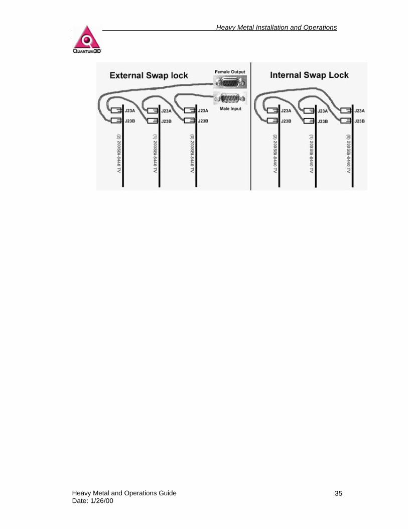
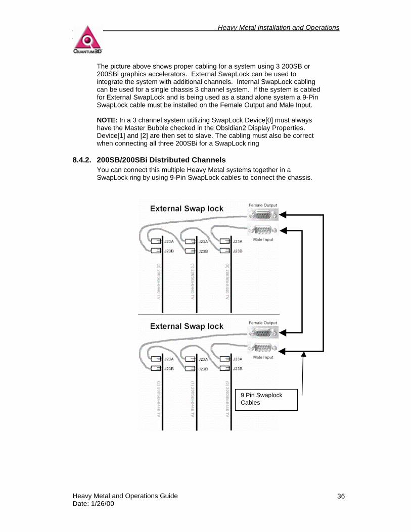
The picture above shows proper cabling for a system using 3 200SB or 200SBi graphics accelerators. External SwapLock can be used to integrate the system with additional channels. Internal SwapLock cabling can be used for a single chassis 3 channel system. If the system is cabled for External SwapLock and is being used as a stand alone system a 9-Pin SwapLock cable must be installed on the Female Output and Male Input. NOTE: In a 3 channel system utilizing SwapLock Device[0] must always have the Master Bubble checked in the Obsidian2 Display Properties. Device[1] and [2] are then set to slave. The cabling must also be correct when connecting all three 200SBi for a SwapLock ring
8.4.2. 200SB/200SBi Distributed Channels You can connect this multiple Heavy Metal systems together in a SwapLock ring by using 9-Pin SwapLock cables to connect the chassis.
9 Pin Swaplock Cables
Heavy Metal Installation and Operations Guide
Heavy Metal and Operations Guide Date: 1/26/00
37
8.5. Application Startup Applications driving the SwapLock channels must initialize graphics operations in the correct order, otherwise a SwapLock deadlock can occur. OpenGVS applications that use the Multi-frame buffer utility functions will automatically enable the devices in the order that they are enumerated. If you are developing in Glide or SimGL the devices should be initialized in increasing order. Device 0 must be the master in the Obsidian2 Display Properties. If you have more than one application running on multiple PCs then the applications should send information via ethernet to signal that the applications have finished initialization and is ready to loop through the enumerated devices issuing grBufferSwap calls. Typically in this configuration each Heavy Metal PC has only a singlegraphics device.
8.6. Application Shutdown Applications driving the SwapLock channels must shuitdown graphics operations in the correct order, if one channel is shutdown or halts unexpectedly even channel must be brought down and re-initialized. This means that the application must free all graphics resources, call grGlideShutdown() and then re-initialize all graphics devices with grGlideInit.
8.7. SwapLocking Various Obsidian2 Graphics Systems SwapLock can also be done with a combination of 200SBi and Mercury To use Mercury and the 200SBi in a multi-channel SwapLock configuration, the 200SBi must have the Master bubble checked in the Obsidian2 Display Propertied Tab. A Mercury can be a slave to the 200SBi but the 200SBi cannot be a slave to Mercury.
Heavy Metal Installation and Operations Guide
Heavy Metal and Operations Guide Date: 1/26/00
38
9. Using Obsidian2 Display Properties
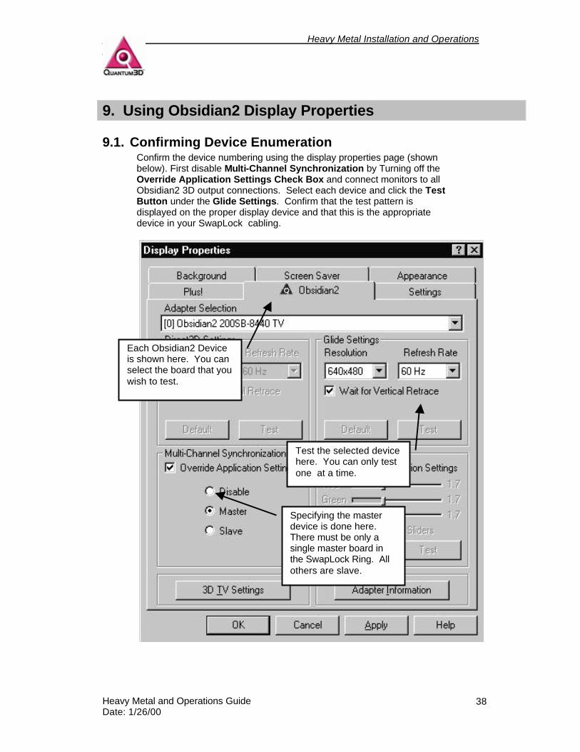
9.1. Confirming Device Enumeration Confirm the device numbering using the display properties page (shown below). First disable Multi-Channel Synchronization by Turning off the Override Application Settings Check Box and connect monitors to all Obsidian2 3D output connections. Select each device and click the Test Button under the Glide Settings. Confirm that the test pattern is displayed on the proper display device and that this is the appropriate device in your SwapLock cabling.
Specifying the master device is done here. There must be only a single master board in the SwapLock Ring. All others are slave.
Each Obsidian2 Device is shown here. You can select the board that you wish to test.
Test the selected device here. You can only test one at a time.

Heavy Metal Installation and Operations Guide
Heavy Metal and Operations Guide Date: 1/26/00
39
9.2. Using the Glide Test You can use the Glide Test Button to test the operation of the graphics accelerator. By changing the Display Resolution, Display Frequency and Gamma Correction values you can see the results using the Test Button under Glide Settings.
9.3. Using the Adapter Information This button will give you information on the Adapter and Current Revision of the drivers that are installed on your system. This information is very useful to Quantum3D Technical Support and should be noted before calling for technical support.
Heavy Metal Installation and Operations Guide
Heavy Metal and Operations Guide Date: 1/26/00
40
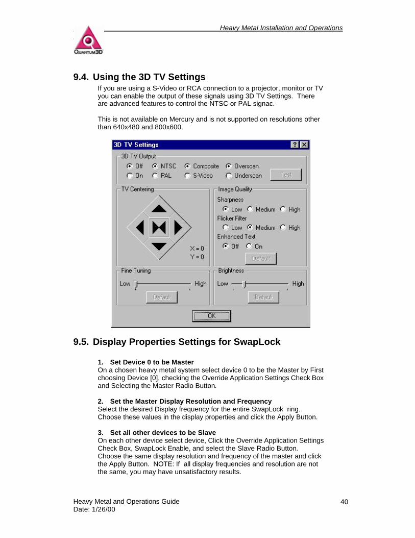
9.4. Using the 3D TV Settings If you are using a S-Video or RCA connection to a projector, monitor or TV you can enable the output of these signals using 3D TV Settings. There are advanced features to control the NTSC or PAL signac. This is not available on Mercury and is not supported on resolutions other than 640x480 and 800x600.
9.5. Display Properties Settings for SwapLock
1. Set Device 0 to be Master On a chosen heavy metal system select device 0 to be the Master by First choosing Device [0], checking the Override Application Settings Check Box and Selecting the Master Radio Button. 2. Set the Master Display Resolution and Frequency Select the desired Display frequency for the entire SwapLock ring. Choose these values in the display properties and click the Apply Button. 3. Set all other devices to be Slave On each other device select device, Click the Override Application Settings Check Box, SwapLock Enable, and select the Slave Radio Button. Choose the same display resolution and frequency of the master and click the Apply Button. NOTE: If all display frequencies and resolution are not the same, you may have unsatisfactory results.

Heavy Metal Installation and Operations Guide
Heavy Metal and Operations Guide Date: 1/26/00
41
4. Testing The SwapLock Configuration The basic fly demonstration within OpenGVS SDK demos is adapted to support mutiple channels within a single system. Build gem\gv\demos\fly\basic demos, and edit msf.bat to reflect a –m=4 switch, where 4 is the maximum number of accelerators in your systems. This can then be executed on the system designated with the Master 200SB and then on all the remaining systems. All channels should display and be SwapLock ed. If the Master system is closed before the slaves, then the slave fly applications will hang, and must be terminated with End Process from the Task Manager.
Heavy Metal Installation and Operations Guide
Heavy Metal and Operations Guide Date: 1/26/00
42
10. Included Software
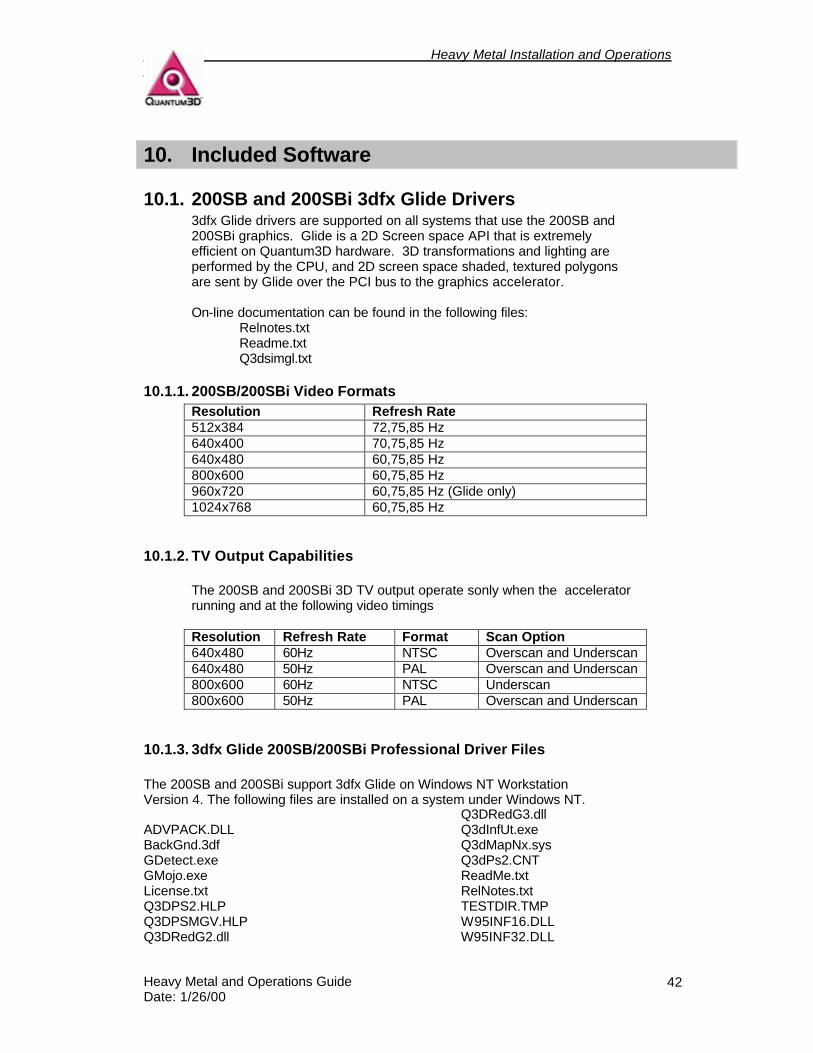
10.1. 200SB and 200SBi 3dfx Glide Drivers 3dfx Glide drivers are supported on all systems that use the 200SB and 200SBi graphics. Glide is a 2D Screen space API that is extremely efficient on Quantum3D hardware. 3D transformations and lighting are performed by the CPU, and 2D screen space shaded, textured polygons are sent by Glide over the PCI bus to the graphics accelerator. On-line documentation can be found in the following files:
Relnotes.txt Readme.txt Q3dsimgl.txt
10.1.1. 200SB/200SBi Video Formats Resolution Refresh Rate 512x384 72,75,85 Hz 640x400 70,75,85 Hz 640x480 60,75,85 Hz 800x600 60,75,85 Hz 960x720 60,75,85 Hz (Glide only) 1024x768 60,75,85 Hz
10.1.2. TV Output Capabilities The 200SB and 200SBi 3D TV output operate sonly when the accelerator running and at the following video timings Resolution Refresh Rate Format Scan Option 640x480 60Hz NTSC Overscan and Underscan 640x480 50Hz PAL Overscan and Underscan 800x600 60Hz NTSC Underscan 800x600 50Hz PAL Overscan and Underscan
10.1.3. 3dfx Glide 200SB/200SBi Professional Driver Files The 200SB and 200SBi support 3dfx Glide on Windows NT Workstation Version 4. The following files are installed on a system under Windows NT. ADVPACK.DLL BackGnd.3df GDetect.exe GMojo.exe License.txt Q3DPS2.HLP Q3DPSMGV.HLP Q3DRedG2.dll
Q3DRedG3.dll Q3dInfUt.exe Q3dMapNx.sys Q3dPs2.CNT ReadMe.txt RelNotes.txt TESTDIR.TMP W95INF16.DLL W95INF32.DLL
Heavy Metal Installation and Operations Guide
Heavy Metal and Operations Guide Date: 1/26/00
43
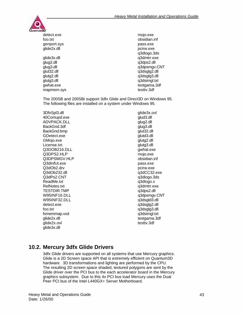
detect.exe foo.txt genport.sys glide2x.dll glide3x.dll glug2.dll glug3.dll glut32.dll glutg2.dll glutg3.dll gwhat.exe mapmem.sys
mojo.exe obsidian.inf pass.exe pcirw.exe q3dlogo.3ds q3dmtrr.exe q3dps2.dll q3dpsmgv.CNT q3dsglg2.dll q3dsglg3.dll q3dsimgl.txt testgama.3df testtv.3df
The 200SB and 200SBi support 3dfx Glide and Direct3D on Windows 95. The following files are installed on a system under Windows 95. 3DfxSpl3.dll 40Comupd.exe ADVPACK.DLL BackGnd.3df BackGnd.bmp GDetect.exe GMojo.exe License.txt Q3DOB216.DLL Q3DPS2.HLP Q3DPSMGV.HLP Q3dInfUt.exe Q3dOb2.drv Q3dOb232.dll Q3dPs2.CNT ReadMe.txt RelNotes.txt TESTDIR.TMP W95INF16.DLL W95INF32.DLL detect.exe foo.txt fxmemmap.vxd glide2x.dll glide2x.ovl glide3x.dll
glide3x.ovl glud3.dll glug2.dll glug3.dll glut32.dll glutd3.dll glutg2.dll glutg3.dll gwhat.exe mojo.exe obsidian.inf pass.exe pcirw.exe q3dCC32.exe q3dlogo.3ds q3dlogo.x q3dmtrr.exe q3dps2.dll q3dpsmgv.CNT q3dsgld3.dll q3dsglg2.dll q3dsglg3.dll q3dsimgl.txt testgama.3df testtv.3df
10.2. Mercury 3dfx Glide Drivers 3dfx Glide drivers are supported on all systems that use Mercury graphics. Glide is a 2D Screen space API that is extremely efficient on Quantum3D hardware. 3D transformations and lighting are performed by the CPU. The resulting 2D screen space shaded, textured polygons are sent by the Glide driver over the PCI bus to the each accelerator board in the Mercury graphics subsystem. Due to this 4x PCI bus load Mercury uses the Dual Peer PCI bus of the Intel L440GX+ Server Motherboard.

Heavy Metal Installation and Operations Guide
Heavy Metal and Operations Guide Date: 1/26/00
44
Heavy Metal Installation and Operations Guide
Heavy Metal and Operations Guide Date: 1/26/00
45
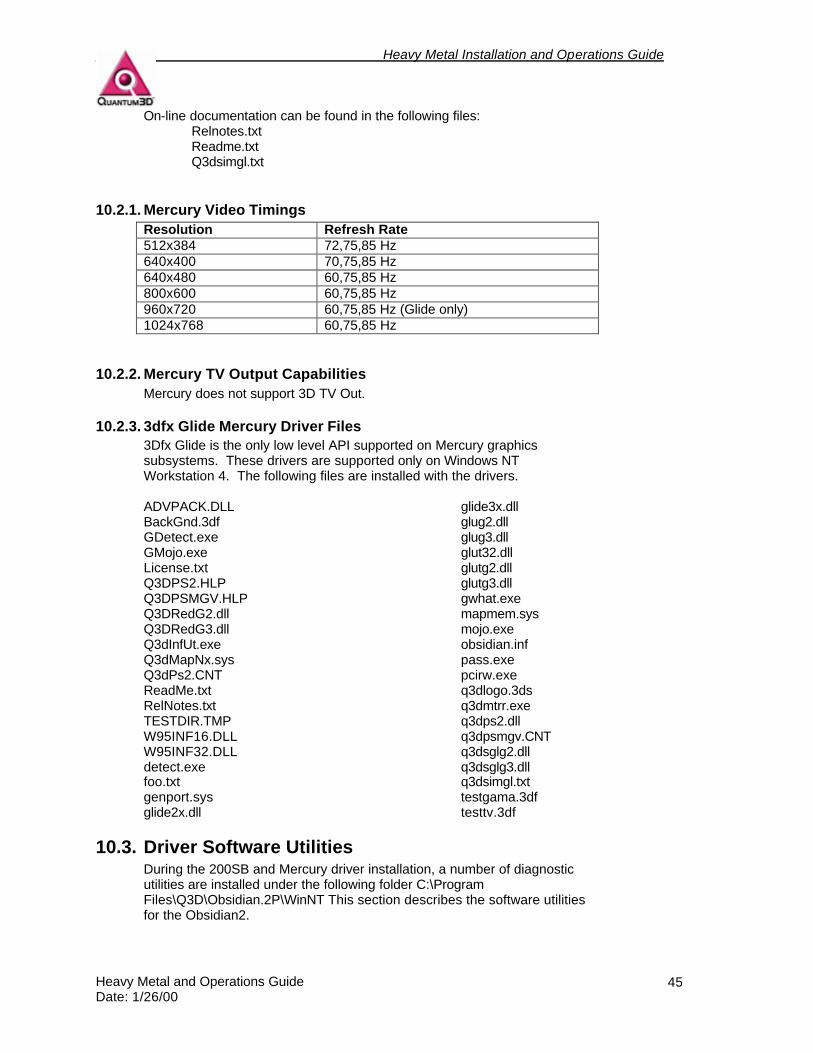
On-line documentation can be found in the following files: Relnotes.txt Readme.txt Q3dsimgl.txt
10.2.1. Mercury Video Timings Resolution Refresh Rate 512x384 72,75,85 Hz 640x400 70,75,85 Hz 640x480 60,75,85 Hz 800x600 60,75,85 Hz 960x720 60,75,85 Hz (Glide only) 1024x768 60,75,85 Hz
10.2.2. Mercury TV Output Capabilities Mercury does not support 3D TV Out.
10.2.3. 3dfx Glide Mercury Driver Files 3Dfx Glide is the only low level API supported on Mercury graphics subsystems. These drivers are supported only on Windows NT Workstation 4. The following files are installed with the drivers. ADVPACK.DLL BackGnd.3df GDetect.exe GMojo.exe License.txt Q3DPS2.HLP Q3DPSMGV.HLP Q3DRedG2.dll Q3DRedG3.dll Q3dInfUt.exe Q3dMapNx.sys Q3dPs2.CNT ReadMe.txt RelNotes.txt TESTDIR.TMP W95INF16.DLL W95INF32.DLL detect.exe foo.txt genport.sys glide2x.dll
glide3x.dll glug2.dll glug3.dll glut32.dll glutg2.dll glutg3.dll gwhat.exe mapmem.sys mojo.exe obsidian.inf pass.exe pcirw.exe q3dlogo.3ds q3dmtrr.exe q3dps2.dll q3dpsmgv.CNT q3dsglg2.dll q3dsglg3.dll q3dsimgl.txt testgama.3df testtv.3df
10.3. Driver Software Utilities During the 200SB and Mercury driver installation, a number of diagnostic utilities are installed under the following folder C:\Program Files\Q3D\Obsidian.2P\WinNT This section describes the software utilities for the Obsidian2.
Heavy Metal Installation and Operations Guide
Heavy Metal and Operations Guide Date: 1/26/00
46
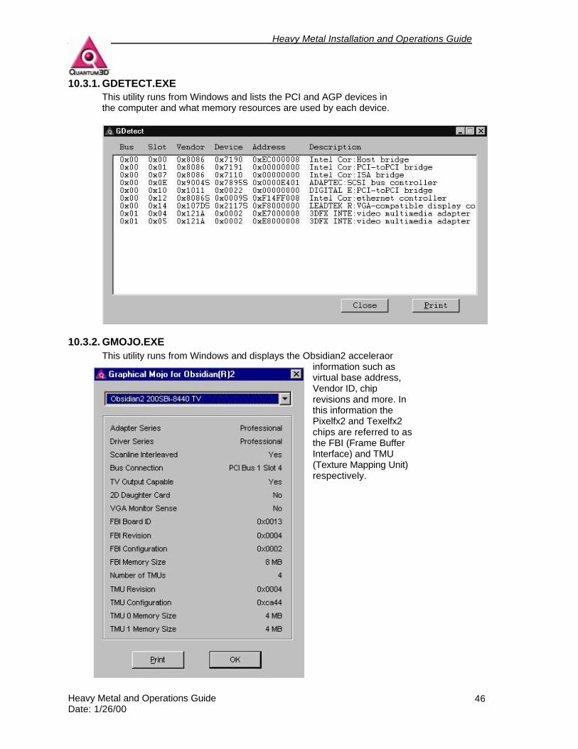
10.3.1. GDETECT.EXE This utility runs from Windows and lists the PCI and AGP devices in the computer and what memory resources are used by each device.
10.3.2. GMOJO.EXE This utility runs from Windows and displays the Obsidian2 acceleraor
information such as virtual base address, Vendor ID, chip revisions and more. In this information the Pixelfx2 and Texelfx2 chips are referred to as the FBI (Frame Buffer Interface) and TMU (Texture Mapping Unit) respectively.

Heavy Metal Installation and Operations Guide
Heavy Metal and Operations Guide Date: 1/26/00
47
10.3.3. DETECT.EXE Detect is a utility that prints the same information as that printed by gdetect. Because it is in a window you can easily copy and paste the text into a file. For example using the command detect > detect.txt will create a file named detect.txt that can be printed or emailed to Quantum3D Technical Support.
10.3.4. MOJO.EXE

Heavy Metal Installation and Operations Guide
Heavy Metal and Operations Guide Date: 1/26/00
48
10.3.5. GWHAT.EXE This program prints the version information for the files specified on the command line.
10.3.6. PASS.EXE This program enables pass through. It is not recommended to run this application on a single monitor system that uses a pass through cable since you will not be able to regain control over the monitor. On a dual monitor configuration the Obsidian2 Display Properties can be used to regain control over the windows display.
10.3.7. PCIRW.EXE This program gives the same information as detect.exe
Heavy Metal Installation and Operations Guide
Heavy Metal and Operations Guide Date: 1/26/00
49
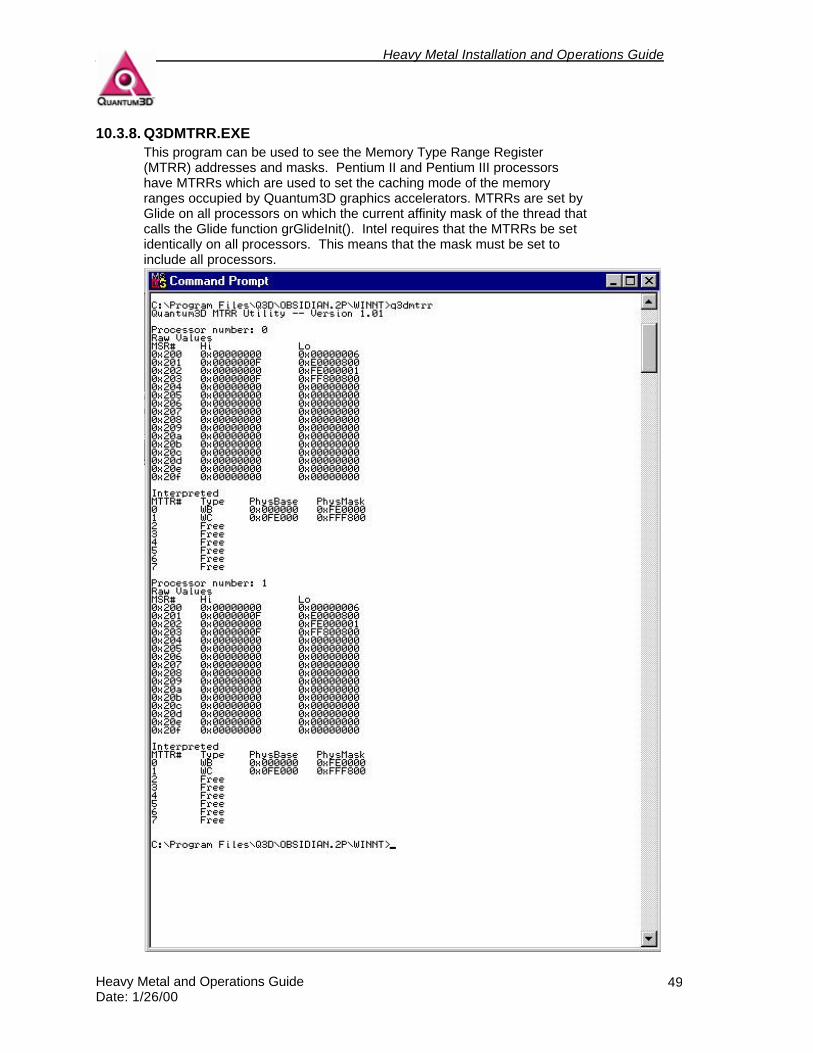
10.3.8. Q3DMTRR.EXE This program can be used to see the Memory Type Range Register (MTRR) addresses and masks. Pentium II and Pentium III processors have MTRRs which are used to set the caching mode of the memory ranges occupied by Quantum3D graphics accelerators. MTRRs are set by Glide on all processors on which the current affinity mask of the thread that calls the Glide function grGlideInit(). Intel requires that the MTRRs be set identically on all processors. This means that the mask must be set to include all processors.
Heavy Metal Installation and Operations Guide
Heavy Metal and Operations Guide Date: 1/26/00
50
10.4. SimGL
10.4.1. How to get SimGL SimGL is supplied with Quantum3D 200SB/200SBi and Mercury drivers. When the drivers are extracted SimGL files will be in the Winnt folder. The files distributed with SimGL are:
glug2.dll glu that calls q3dsglg2.dll glug3.dll glu that calls q3dsgl32.dll glut32.dll glut that calls glutg2.dll and glutg3.dll glutg2.dll glut that calls q3dsglg2.dll glutg3.dll glut that calls q3dsglg3.dll q3dsglg2.dll SimGL library for Glide 2 q3dsglg3.dll SimGL library for Glide 3 q3dsimgl.txt SimGL Documentation
If you require static library files (.lib) files in order to link your application program with SimGL contact Quantum3D Technical Support.
10.4.2. Running with SimGL If the application has been linked against the OpenGL library, place SimGL (q3dsglg2.dll or q3dsglg3.dll) in the directory along with the application or in the system directory, rename the file to opengl32.dll. More details are supplied with the SimGL SDK or q3dsimgl.txt. This file is delivered with SimGL. If the application has been linked against a SimGL library, then all that needs to be done is to place the desired SimGL library in the current working directory, a directory in the application’s path or in the system directory. The same must be done for the GLU utility libraries if they are also being used.
10.4.3. How SimGL works on Obsidian2 Graphics Quantum3D Obsidian and Obsidian2 graphics subsystems support full screen 3D only. These accelerators are secondary display devices in Windows 9X and Windows NT. The application program's OpenGL window will appear on the Windows desktop as normal, but will appear blank. The SimGL 3D graphics output will appear on the secondary display and will be positioned in the lower left corner. The SimGL view port will be the same size, measured in pixels as the OpenGL window on the primary display. If a single display and the pass through feature of the Obsidian2 is used, only the SimGL 3D view port will be viewable. SimGL has been optimized for Display List rendering so even though immediate mode is fas, it is not as efficient.
10.4.4. Background and History SimGL, although identical in many ways to the OpenGL API published by SGI, has some key differences and benefits. The technology used in SimGL can help application developers by providing a highly optimized API specifically designed for realtime 3D graphics. In general, SimGL can be considered a subset of OpenGL specifically designed and optimized for interactive 3D graphics applications.
Heavy Metal Installation and Operations Guide
Heavy Metal and Operations Guide Date: 1/26/00
51
SimGL’s history stems from the port of Quantum3D’s OpenGVSs scene management software to the 3dfx® Glide graphics API. Since OpenGVS is based on OpenGL, the port to a 3dfx platform drove the development of an abstraction layer of software called Subset GL or SGL. In 1997, the lack of OpenGL drivers for the 3dfx Voodoo and Voodoo2 chipsets led to agreements between Quantum3D and 3dfx that resulted in a teamed effort of to form the product SimGL.
10.4.5. What is OpenGL? An excerpt from http://www.OpenGL.org defines OpenGL states: "OpenGL fosters innovation and speeds application development by incorporating a broad set of rendering, texture mapping, special effects, and other powerful visualization functions. Developers can leverage the power of OpenGL across all popular desktop and workstation platforms, ensuring wide application deployment." Although this is not a complete technical description of OpenGL, this is a good starting point for comparison. With this said it can be assumed that the OpenGL API in general is not specifically designed for the development of realtime 3D applications. Rather, OpenGL is primarily a robust mechanism for programming any 3D graphics application, which would include CAD/CAM, games, realtime 3D and more. Developers using OpenGL to develop a realtime 3D application must be very cautious not to use OpenGL functionality that may have an adverse affect on realtime performance on the target platform. Calling the wrong function can result in an intense amount of CPU or graphics computation that will likely severely impact an application’s performance. A generic OpenGL compliant driver does not alone guarantee realtime performance; in fact, it could imply otherwise.
10.4.6. What is SimGL? SimGL is an API that uses the same calling conventions as OpenGL. The function calls for SimGL are identical to OpenGL including arguments and function names. SimGL does not implement a compliant OpenGL driver. This means that not all functions are implemented and not all computations performed by the API are done in a compliant manner. SimGL has two native graphics APIs as its foundation; Direct3D and Glide. SimGL is a very fast API and it is not only fast on 3dfx graphics accelerators —the Direct3D implementation is fast on all PC graphics accelerators. SimGL is typically faster than OpenGL because of the internal optimization done specifically for realtime 3D operations. In most cases using SimGL rather then OpenGL display drivers will result in increased performance, regardless of the accelerator being used. Display List operation performs extremely well in the SimGL API. SimGL is authenticated on Quantum3D Obsidian and Obsidian2 Professional graphics subsystems and does not require a license for Quantum3D Professional graphics subsystems and systems products.
10.4.7. SimGL Use of Low level Graphics APIs SimGL has implementations that use Microsoft Direct3D and 3dfx Glide graphics APIs. Both Glide 2.X and Glide 3.X are supported by SimGL. SimGL DLLs for the Direct3D and Glide versions are available with all Quantum3D Professional Drivers. Versions of the GLU libraries are also
Heavy Metal Installation and Operations Guide
Heavy Metal and Operations Guide Date: 1/26/00
52
available for applications developers that link directly with SimGL and also use GLU.
10.4.8. Developing an Application with SimGL Developers must have access to the SimGL SDK. This SDK can be delivered as part of the OpenGVS SDK or as a standalone SimGL SDK. Either SDK can be obtained from a Quantum3D sales representative. OpenGL applications must be linked against SimGL. This enables the application to run in an OpenGL or SimGL runtime environment. It is possible to use OpenGL and SimGL simultaneously in the application if the application loads either the OpenGL DLL or SimGL DLL.
10.4.9. OpenGL Functions available in SimGL Some functions in SimGL offer only a partial implementation of the OpenGL functionality. Many functions are defined only as stubs and issue a warning message the first time they are called. For a complete for a complete up-to-date list of these functions see the appendices of the SimGL document q3dsimgl.txt that is supplied with the SimGL SDK.
10.4.10. SimGL Extension Functions SimGL implements certain extensions that enable users to take advantage of unique features of Quantum3D Obsidian and Obsidian2 hardware. Extensions are also available for multi-channel support. This enables the development of PC systems that utilize more than one graphics accelerator per system. Other extensions are available to perform extremely efficient clipping and lighting. Other SimGL hint functions are available to avoid certain limitations of the range of texture coordinates on polygon vertices.
10.4.11. Conclusion SimGL is a high performance API designed specifically for realtime 3D application development. It is a more efficient API that gives you improved performance over standard (compliant) OpenGL drivers. Because of SimGL's history and background with OpenGVS, it supports and is optimized for the specific functions needed by simulation and deployment applications. SimGL is a realtime 3D API used for application developers that require efficiency and high performance graphics. For more technical information on SimGL, please contact [email protected].
10.5. Useful Environment Variables
10.5.1. SSTV2_MDETECT If set to one, this forces the drivers to detect the presence of a monitor, even if one is not connected.
10.5.2. SST_DUALHEAD If set to 1 the drivers that we are running with 2 monitors, one for 2D and one for 3D. This is used by the Glide driver and by OpenGVS. OpenGVS will use this and automatically reduce the size of the Mouse Arena in a way that you can easily navigate windows.
Heavy Metal Installation and Operations Guide
Heavy Metal and Operations Guide Date: 1/26/00
53
10.5.3. GV_PATH_MODELS A list of directories, separated by semi-colon (;) which tells OpenGVS where to search for external models if not found in normal model locations (as specified by the model).
10.5.4. TXTPATH A list of directories, separated by semi-colon (;) that tells OpenGVS where to search for external models if not found in normal model locations (as specified by the model). The default value for this environment variable is.
10.5.5. GV_ENV_SPLASH If set to 0 this will disable the OpenGVS splash window.
10.5.6. GV_ENV_FBF_RESOLUTION Used to set the resolution of the Frame Buffer to the desired (valid) resolution. For example:
set GV_ENV_FBF_RESOLUTION=640x480.
10.5.7. GV_ENV_FBF_UNIT If there is more than one frame buffer in a system, use only the one specified in the variable. For example if you have 2 accelerators installed and GV_ENV_FBF_UNIT is set to 1, then you will use the second device detected on the PCI Bus. If you set to 0, then you will use the first (which is default).
10.5.8. GV_ENV_SGL_SSE IF set to 0, the drivers will disable Pentium III SSE optimizations.
10.5.9. FX_GLIDE_NO_SPLASH If set to 0, the drivers will not display the 3dfx logo on initialization.
10.5.10. FX_GLIDE_SHAMELESS_PLUG If set to 1, the drivers will enable the Quantum3D Shameless plug.
10.5.11. FX_GLIDE_SWAPINTERVAL If set to a integer value the driver function call to grBufferSwap will be called only between FX_GLIDE_SWAPINTERVAL vertical retrace intervals.
10.5.12. SST_INITDEBUG Set to 0, the drivers will not produce any debug text. Set to 3 or more will result in verbose information.
10.5.13. SST_INITDEBUG_FILE Specify the name of the file that will contain the driver debug text.
10.6. OpenGVS Realworld Benchmarks The purpose of the benchmarks is to help users evaluate 3D products that are being considered for realtime roles such as visual simulation and

Heavy Metal Installation and Operations Guide
Heavy Metal and Operations Guide Date: 1/26/00
54
training applications. The performance test suite was unique when it was introduced because it allowed users to compare UNIX 3D graphics workstations to 3D hardware solutions on the PC. This was possible because the benchmark application software was written using OpenGVS, a highly portable realtime scene management API for 3D developers. The benchmarks remain unique because they support all the leading rendering APIs: OpenGL, Microsoft Direct3D, and 3Dfx Glide2 (and now Glide3). OpenGVS Realworld Benchmarks com pre-installed on heavy Metal Systems. For more information about RWB please see: • StartMenu/Programs/OpenGVS RWB 2.3/Frequently Asked Questions • StartMenu/Programs/OpenGVS RWB 2.3/Overview Document • StartMenu/Programs/OpenGVS RWB 2.3/Readme
Heavy Metal Installation and Operations Guide
Heavy Metal and Operations Guide Date: 1/26/00
55
11. Trouble Shooting
11.1. Power on issues The following problems can occur during startup of the system. If you experience any of these problems, follow the defined procedures to diagnose and fix the problem. The primary resource for the problems below is the motherboard documentation. However, Quantum3D Technical Support, the Quantum3D website, and component manufacturers documents are excellent technical resources. See the websites listed under section 13 for more information if you require it.
11.1.1. System Beeps Beeps during system startup usually indicate a problem with the Primary Display Adapter, Memory, or CPUs. Consult the motherboard documentation for a complete description of these beeps. Trouble shooting guides may be found in the SuperMicro Super P6DBS User’s and BIOS Manual Chapter 3 and in the L440GX+ Server Board product guide, Chapter 4.
11.1.2. No Video Signal If there is no video signal and you hear beeps during the POST, you should look in the Motherboard documentation listed in the previous section. If everything else appears normal, check to make sure that your monitor cable connections are to the Primary Display Device. If you are operating with a single monitor, confirm connections of the Monitor Pass Through (Medusa) cable.
11.1.3. Processor(s) Not Recognized If your system has been delivered with 2 CPUs, but they are not recognized, you may need to use a BIOS setting to retest for both processors. Restart the system and enter the BIOS setup. Choose the server settings and choose to retest for processors during startup. Exit the BIOS and ave changes. If they are operating correctly both processors will be recognized.
11.1.4. Processor Fails Test Consult the motherboard documentation for a complete description of these processor tests in the Trouble Shooting or Solving Problem sections. If a processor fails a test then the processor may be defective, not seated properly, or the motherboard BIOS may be corrupt. You will need to seat the CPU properly after powering down the system and then flash the motherboard BIOS and with the latest BIOS revision.
11.1.5. Boot device not found This could be the result of a device failure, power connection, device cabling, or improper BIOS settings. Confirm that your disk drive is locked in place with the key. If the disk drive LED is displaying a solid number then it is locked in place properly. If the disk drive displays a U then you
Heavy Metal Installation and Operations Guide
Heavy Metal and Operations Guide Date: 1/26/00
56
must power off the system, place the key in the drive and lock it shut. When the disk drive is locked you should not be able to remove it from the bay. Confirm that the device is found by the BIOS by checking the peripheral settings. The BIOS should find IDE CDROM, Floppy Drive, and Hard Disk drives. The BIOS should also specify device boot order. Removable drives are tested for a bootable file system first, then the hard disk. If the BIOS does not find a device, it may not have the ribbon cable or power cable connected properly.
11.1.6. Where to find additional information Additional information may be found in the motherboard documentation, FAQs on the web or through Quantum3D Technical Support.
11.2. Systems Operation Problems Below are some basic problems that can happen during the time that you are operating the system. If you experience a problem, are unable to resolve it, and believe it is the result of a defective Quantum3D hardware or software product, please contact Quantum3D Technical Support.
11.2.1. NMI Memory Parity Errors If you receive NMI Memory Parity errors regularly during graphics operations, they could be a result of problems the application software or Quantum3D Obsidian2 Drivers. In these cases the problem is not related to RAM. Rather it is a side effect of a problem in the application software or driver. It has been found that floating point exceptions in the Intel Pentium III SIMD instructions are not always trapped properly and instead of raising an access violation only, they also create NMI Memory Parity Errors. Other problems with bad pointers, access violations, or linear frame buffer reads without locking the frame buffer may cause what appear to be a memory parity error. To debug these types of problems you can disable PERR in the BIOS. You must use Quantum3D Obsidian2 drivers release 5.1 or greater to eliminate the drivers as a possible cause to the problem. If your system has NMI memory parity errors during normal operation (non-graphics or PCI Bus intensive), you probably need to replace the memory.
11.2.2. BSOD with Stack Dump Typically BSODs are the result of a software bug or hardware problem. You should first attempt to reproduce the problem. If the problem is reproducible, you should provide this information to the appropriate software vendor for the application you are using. If the problem appears to be related to hardware contact the appropriate hardware vendor or contact Quantum3D Technical Support.
11.2.3. Cannot Login to Administrator Account The Administrator Account has been provided without a password. To login, type Administrator in the user name field and press the enter key. If this does not work, contact Quantum3D Technical Support.
11.2.4. Problem starting some services It is normal for the system to fail to start network services. After connecting your network and specifying the proper network properties this message
Heavy Metal Installation and Operations Guide
Heavy Metal and Operations Guide Date: 1/26/00
57
will go away. If it continues, consult the Event Log to determine the source of the problem.
11.2.5. Cannot logon properly, hour glass never goes away This could mean that the Secondary Display Device did not initialize properly. Try using ctrl-alt-delete to raise the task manager. If there is a rundll32 process running, end the process. The system should logon as normal. Use the Glide Test under Display Properties/Obsidian2 to test the Secondary device(s). If they operate, then reboot. If the problem persists, check the Obsidian2 200SBi FAQ, Mercury FAQ or the Heavy Metal FAQ on Quantum3D’s website where there are other suggestions for resolving this issue.
11.2.6. Where to find additional information Additional information may be found in the motherboard documentation, FAQs on the web or through Quantum3D Technical Support.
11.3. Graphics Issues
11.3.1. Black Screen on 3D Device Confirm that a monitor cable is connected to the short end of the monitor adapter. Confirm that the monitor is operating and is capable of the resolution and refresh rate as it is specified in the Obsidian2 Display Properties. Confirm that you have SwapLock cables configured for single channel operation and that SwapLock is currently disabled in the Obsidian2 Display Properties.
11.3.2. Graphics Freeze on First Frame This usually means that you do not have the SwapLock cables properly installed for single channel use, or are trying to run a SwapLock slave and not all channels are up and running.
11.3.3. Flashing and Tearing on the 3D Device The Wait for Vertical Retrace Flag is turned off in the Obsidian2 Display Properties or FX_GLIDE_SWAPINTERVAL is set to 0.
11.3.4. Glide Test is Not Active Another application is already using the Graphics Accelerator or did not complete successfully. Close all windows and use the Task Manager to kill any stray applications that are using Glide or any rundll processes.
11.3.5. Mutual Exclusion Error Another application is already using the Graphics Accelerator or did not complete successfully. Close all windows and use the Task Manager to kill any stray applications that are using Glide or any rundll processes.
11.3.6. Where to Find Additional Information Additional trouble shooting information can be found with the supplemental FAQ documents, or at the Quantum3D web site.

Heavy Metal Installation and Operations Guide
Heavy Metal and Operations Guide Date: 1/26/00
58

Heavy Metal Installation and Operations Guide
Heavy Metal and Operations Guide Date: 1/26/00
59
12. Recovering Your System In the event that you have a software configuration issue or failed hard disk, you may need to restore the original hard disk image. To do this you will use a bootable CDROM that is supplied by Quantum3D. This process will destroy all contents of the disk as well as assign a new System ID#. You should backup all user data on the C: Drive, since you will restore the image onto this drive. Restart the system, enter the BIOS and confirm that the boot checks the CDROM drive before the hard disk (change if necessary). Place the Recovery CDROM in the drive and Save and/or Exit the BIOS to continue booting. The system will boot to a stripped down version of Windows 95. Partition Quest Restore Image will enable you to recover your system to a base configuration. To recover perform the following steps. 1) Click on the Restore Image Button 2) Click the Browse Button 3) Choose the .PQI file for your licensed Operating System, Click OK,
Click Next 4) Select the Destination Partition or Free Space 5) The software will notify you that it will delete this partition in order to
restore 6) Click OK to confirm that the new partition will be automatically resized 7) Choose Fast Mode, Click OK, then Finish 8) Click No to view results 9) Click the exit button 10) Press and release the reset button on the computer After completing these steps your system will be configure as follows
a. System Drivers are installed (i.e. SCSI, CDROM) b. Video Drivers are installed (Viper 770) c. Mercury Drivers are installed (GX+ Only)
Your system will require a new SID or obtain the SID from your DNS server. You need to configure the network protocol to work on your LAN. If you have a 200SB or 200Sbi you will need to download the latest drivers and install them on the system. Use Add/Remove Programs to remove exiting Quantum3D Obsidian2 200SB drivers. Use the OpenGVS Realworld Benchmarks CDROM to install the these benchmarks. For proper operation on Quantum3D Obsidian2 200SB and Mercury install the Glide versions (Glide 2 and Glide 3). Use the OpenGVS SDK disk to install the OpenGVS Software Development Kit. Choose all of the options that you wish to install. You will need a new key to match your new computer SID.
Heavy Metal Installation and Operations Guide
Heavy Metal and Operations Guide Date: 1/26/00
60
13. System Options Heavy Metal systems can be ordered with a number of configurable hardware options. These options are outlined below. The latest drivers for these hardware options can be found on manufacturers’ websites. Drivers qualified by Quantum3D can be found on the Quantum3D systems drivers web site at http://www.quantum3d.com/support/Sysdrivers/Device_drivers.html
13.1. Motherboards Motherboards for the Quantum3D Heavy Metal Family are the latest high performance motherboards based on the Intel 440BX and 440GX+ chipsets.
13.1.1. Heavy Metal BX Motherboard Make and Model SuperMicro P6DBS Specifications and Documentation See motherboard documentations supplied with the system. Motherboard Manufacturer Web Site Home Page
http://www.supermicro.com/ To date motherboard documents web page
http://www.supermicro.com/PRODUCT/MotherBoards/440BX/p6dbs.htm
13.1.2. Heavy Metal GX+ Motherboard Make and Model Intel L440GX+ Specifications and Documentation See motherboard documentations supplied with the system Motherboard Manufacturer Web Site Home Page
http://www.intel.com/ To date motherboard documents web page
http://support.intel.com/support/motherboards/server/L440GX/
13.2. Primary Video Options The 2D Windows accelerator installed on a Heavy Metal system depends upon which system you have purchased. Drivers for the 2D Video Cards are preinstalled on your system. Outlined below are the 2D Video Options for Heavy Metal BX and Heavy Metal GX+. If your display adapter is not listed here it is likely you have a custom configuration and you should review your Bill of Materials.
13.2.1. Heavy Metal BX Primary Video Options Voodoo 3: Ventana3 and Voodoo3 Accelerators are the fastest accelerators offered by Quantum3D as a Primary Display Device. These devices are fast enough to perform many realtime 3D functions without the need for a secondary display device. Manufacturer URL
Heavy Metal Installation and Operations Guide
Heavy Metal and Operations Guide Date: 1/26/00
61
http://www.quantum3d.com To Date Product URL
http://www.quantum3d.com/product%20pages/voodoo3.html To Date Product FAQ
http://www.3dfx.com/view.asp?IOID=102 To Date Product Drivers URL
http://www.3dfx.com/view.asp?PAGE=nusV3drivers Diamond Viper 770:The Diamond Viper 770 provides excellent 2D imagery with an Nvidia TNT2 chipset with robust Direct3D and OpenGL drivers and 16 MB SDRAM Manufacturer URL http://www.diamondmm.com To Date Product URL
http://www.diamondmm.com/products/current/viperv770.cfm To Date Product FAQ
http://www.diamondmm.com/products/faqs/current/viper_v770-faq.html ATI Rage Pro: Features 8MB of powerful memory and ATI RAGE graphics technology. Manufacturer URL http://www.ati.com To Date Product URL http://www.atitech.com/ca_us/products/pc/aiw_pro/index.html To Date Product Drivers URL
http://support.atitech.ca/drivers/drivers.html To Date Product FAQ
http://support.atitech.ca/info/3drg_pro_inf.html
13.2.2. Heavy Metal GX+ Primary Video Options Cirrus* Logic CL-GD5480: The CL-GD5480 is built onto the L4440GX+ motherboard and provides many advanced management features. See section http://www.cirrus.com To Date Product URL
http://www.cirrus.com/products/overviews/gd5480.html To Date Product Drivers URL
http://support.intel.com/support/motherboards/server/l440gx/5480_NT.HTM
13.3. Realtime 3D Graphics Options Auxiliary or Secondary Display Devices or Graphics Subsystems are means to produce compelling realtime 3D applications. These subsystems are based on 3dfx Voodoo2 and Voodoo3 chipsets. Below is the list of graphics subsystems offered by Quantum3D.
13.3.1. Heavy Metal BX Realtime 3D Graphics Subsystems
Heavy Metal Installation and Operations Guide
Heavy Metal and Operations Guide Date: 1/26/00
62
Quantum3D Obsidian2 200SBi: Quantum3D, Obsidian2 200SBi is a Voodoo2 based accelerator with single board SLI. Typically a single 200SBi is used in each PC for multi-channel systems. This results in the best in scalable performance. However, in cost sensitive applications, more than one 200SBi can be configured in a single Heavy Metal system. This yields a very cost effective solution for multi-channel systems. In the case of the GX+ system with a dual PCI architecture, multiprocessing applications can achieve very high performance. Manufacturer URL http://www.quantum3d.com To Date Product URL
http://www.quantum3d.com/product pages/200sbi.html To Date FAQ URL
http://www.quantum3d.com/support/200SBi.html Voodoo3: Ventana3 and Voodoo3 Accelerators are the fastest accelerators offered by Quantum3D as a Primary Display Device. These devices are fast enough to perform many realtime 3D functions without the need for a secondary display device. Manufacturer URL http://www.quantum3d.com To Date Product URL
http://www.quantum3d.com/product%20pages/voodoo3.html To Date Product FAQ
http://www.3dfx.com/view.asp?IOID=102 To Date Product Drivers URL
http://www.3dfx.com/view.asp?PAGE=nusV3drivers
13.3.2. Heavy Metal GX+ Realtime 3D Graphics Subsystems Quantum3D Mercury: Quantum3D’s Mercury is a Voodoo2 based accelerator using SLI and 4 200SBi accelerators combined to provide full scene hardware anti-aliasing with higher image quality than 2x2 sub pixel anti-aliasing. Mercury is only delivered on Heavy Metal GX+ systems. Multi-channel Mercury systems always use a single Heavy Metal GX+ Mercury for each 3D channel. Manufacturer URL
http://www.quantum3d.com To Date Product URL
http://www.quantum3d.com/product pages/mercury.html To Date FAQ URL
http://www.quantum3d.com/support/Hm_gx.html
13.4. Storage Options Quantum Viking II 4.5 / 9.1 SCSI: The Viking II uses a SCSI interface. It come with either a 4.5 or 9.1 GB formatted capacity. These disks are typically used by default on Heavy Metal GX+ systems. The hard disk is typically mounted in a removable sled manufactured by Kingston. This sled is opened and closed with a key. These removable disks are not
Heavy Metal Installation and Operations Guide
Heavy Metal and Operations Guide Date: 1/26/00
63
currently hot swapping devices. The SCSI controller for Heavy Metal systems is built onto the motherboard. Manufacturer URL
http://www.quantum3d.com To Date Product URL
http://www.quantum3d.com/product pages/200sbi.html To Date FAQ URL
http://www.quantum3d.com/support/200SBi.html Quantum Fireball CX Ultra ATA/66 ATA/4: The Fireball uses an EIDA interface and can be ordered in many capacities ranging from 6.4 to 20.4 GB formatted capacity. The EIDA controller for Heavy Metal systems is built onto the motherboard. Manufacturer URL http://www.quantum.com To Date Product URL
http://www.quantum.com/support/hdd/fireball_cx_ata_support.htm To Date FAQ URL
http://www.quantum.com/products/hdd/resources/hdd_resources.htm Western Digital: Western Digital drives offered in Quantum3D systems use an EIDA interface and can be ordered in many capacities ranging from 10.2 to 27.3 GB formatted capacity. The EIDA controller for Heavy Metal systems is built onto the motherboard. Manufacturer URL http://www.westerndigital.com/ To Date Product URL
http://www.westerndigital.com/products/ To Date FAQ URL
http://www.westerndigital.com/service/
13.5. CD Options Your system will be delivered with either a Toshiba or Sony CDROM.
13.6. Audio Options Any Heavy Metal system may be configured with either of the two following Audio Cards. Aureal Vortex2: Manufacturer URL http://www.aureal.com To Date Product URL
http://www.aureal.com/products/pp_soun.htm To Date Driver URL
http://www.a3d.com/html/download/drivers/
Sound Blaster Family: Manufacturer URL http://www.creative.com/ To Date FAQ URL
http://support.soundblaster.com/faqs/products/
Heavy Metal Installation and Operations Guide
Heavy Metal and Operations Guide Date: 1/26/00
64
To Date Driver URL http://support.soundblaster.com/files/download.asp
13.7. Operating Systems All current versions of Microsoft Operating Systems are supported on Heavy Metal systems. For more information or to place a request to support a certain operating system please contact Quantum3D Technical Support. Heavy Metal BX: Windows98, Windows NT 4 with SP5 Heavy Metal GX+: Windows NT 4 with SP5
13.8. CPU Options Quantum3D currently delivers Heavy Metal systems starting with the Intel Pentium II 450 up to the latest Pentium III products. Manufacturer Home Page
http://www.intel.com/ To date Current CPU Home Page
http://developer.intel.com/design/pentiumiii/ http://developer.intel.com/design/pentiumii/
13.9. Network Options Quantum3D offers the Intel Pro/100+ PCI and Pro/100B PCI Ethernet Network Adapters in Heavy metal BX Systems. This same chipset is built on the L440GX+ motherboard on the Heavy Metal GX+. This adapter support 10 and 100 Mb/s NIC Manufacturer URL http://www.intel.com/ To date 82557 Based NIC datasheet web page
http://support.intel.com/support/network/adapter/pro100/pro100plus/index.htm To Date Driver URL for GX+ Onboard NIC
http://support.intel.com/support/motherboards/server/l440gx/nt_336s.htm To Date Driver URL for BX Add-on Intel PCI NIC
http://support.intel.com/support/network/adapter/pro100/pro100plus/index.htm
13.10. Memory Options Memory can be configured as required. The maximum RAM on Heavy Metal BX is 1 GB. The GX+ has a greater capacity at 2 GB. It is recommended that at a minimum 128 MB RAM is used on all systems and that Quantum3D is consulted for memory upgrades.

Heavy Metal Installation and Operations Guide
Heavy Metal and Operations Guide Date: 1/26/00
65
13.11. I/O Options
13.11.1. Quantum3D GCI2 This is a JAMMA compliant card used for translating the analog and digital controls of joysticks, inertial tracking devices, buttons, coin-mechanisms, and bill acceptors into a digital serial packet format optimized for PC-based deployment. GCI2 Documentation and Drivers can be found at www.quantum3d.com.
13.11.2. High Speed Serial Your system can be delivered with a D-Flex ISA expansion card for high speed serial communications.
Heavy Metal Installation and Operations Guide
Heavy Metal and Operations Guide Date: 1/26/00
66
14. Warranty
14.1. General Warranty Information Quantum3D, Inc. warrants to the original purchaser that the product purchased from Quantum3D, Inc. or from an authorized Quantum3D, Inc. re-seller, excluding software, disks and drivers, compact discs, documentation and related information, is free from defects in parts and/or workmanship for one year from the date of purchase. During this year of warranty period Quantum3D, Inc. or an authorized agent of Quantum3D, Inc. will correct any defects in parts and workmanship at no charge for labor and materials. This warranty is limited to parts and products sold on the original purchase of the system. Add on parts and failures directly caused due to add-on cards or peripherals are not covered in this warranty.
You are responsible for prepaying shipping and insurance expenses incurred in returning the defective product or products. Quantum3D, Inc. is not liable for loss or damage during shipment of your returned system or part. For international shipping, you must prepay export taxes, custom duties and taxes or any other charges associated with return shipment of the product. Replacement products shall be new or serviceable used products, and are warranted for the remainder of the warranty period or 30 days, whichever is longer.
14.2. Warranty Service If at some point you require Warranty Service, you must contact Quantum3D Technical Support at 408-361-9998. If technical support staff determine that a Quantum3D product is defective, a Return Merchandize Authorization (RMA) number will be issued. A replacement product will be sent to you within 10 business days after Quantum3D, Inc. receives the defective part. Quantum3D will replace using the same part or a compatible part of equal capability and performance. Quantum3D is not liable for delays due to the availability of replacement parts. Advance replacement RMA can be done at the purchasers expense (PO or Credit Card). Quantum3D reserves the right to charge purchaser for replacement parts or return the product at purchaser expense, if it is determined that the product is not defective in workmanship.
14.3. Quantum3D Extended Warranty Coverage Extended warranty coverage can be purchased for 10% of the MRSP per additional year if ordered within 90 days of purchase date.
14.4. Quantum3D Express Warranty Coverage Quantum3D Express Warranty Coverage covers advance replacement shipping. Quantum3D will priority ship, next business day replacement product when given a valid Federal Express, DHL or UPS tracking number of the part being returned. Extended Express warranty coverage can be purchased for 5% of the MRSP per additional year if ordered within 30 days of purchase date. Express is free for those products registered and purchased in the Quantum3D Partners plan.

Heavy Metal Installation and Operations Guide
Heavy Metal and Operations Guide Date: 1/26/00
67
Heavy Metal Installation and Operations Guide
Heavy Metal and Operations Guide Date: 1/26/00
68
15. Technical Support Free telephone, email and online support are provided for Heavy Metal systems during the warranty period. In addition to helping with trouble shooting and diagnosing defective parts technical support is prepared to help you with questions about the operation of Quantum3D products.
When you contact technical support Quantum3D might need some background information about the product that you are calling about. Please have the following available to aid our technical support process.
Your Mailing Address and telephone number
The name of the product that you are contacting technical support about
A summary of the question or a description of the problem and, if necessary a method of reproducing the problem
Software used on the system and software added to the system after purchase
Cards added after the original purchase of the system
Technical Support is available from 8:00-5:00PST. Call 408-361-9998 to reach a technical support staff member. Email support is available if you email to mailto:[email protected] or in Europe at mailto:[email protected]. Quantum3D has online technical support resources including FAQs, White Papers and Downloads at http://www.quantum3d.com. Priority Technical Support is available for products registered in the Quantum3D Partners Plan. Registered partners receive a personal, experienced single point of contact in technical support. Access to advanced releases of hardware and software enable you to be prepared for future products. For more information about Quantum3D Partner plans contact [email protected].
Heavy Metal Installation and Operations Guide
Heavy Metal and Operations Guide Date: 1/26/00
69
16. Supplement Materials
16.1. Glossary The glossary on the following page covers terms used in this document.
Heavy Metal Installation and Operations Guide
Heavy Metal and Operations Guide Date: 1/26/00
70
Glossary A AGP: Accelerated Graphics A high-bandwidth 32-bit PC bus that provides up to 528 MBytes/sec to a graphics controller, yielding the bandwidth necessary for texturing directly from system memory. A.G.P. uses memory local to the graphics controller and system memory for graphics data storage. Aliasing: Visual artifacts created by computer graphics that are the result of sampling discrete mathematical values. These artifacts result in flashing, flickering jaggies and other distracting visual effects. Anti-Aliasing: The act of removing aliasing. B Bilinear Blending: The most basic of anti-aliasing techniques for rendering textured objects, bilinear blending removes the hard edge of point sampling by linearly interpolating between adjacent texel colors (in both X and Y dimensions). Bilinear blending results in reduction of pixel fighting when zoomed far out. When used with mipmapping an line artifact is present where mipmap levels change. This can only be anti-aliased further with Trilinear Blending and/or Full screen anti-aliasing. BSOD: Blue Screen of Death. Typically the BSOD is a complete failure of software or hardware. When related to software a valuable stack trace is given.
C D Distributed Channel: Each PC used for a visual channel as a single graphics subsystem. Interchannel communication is done via a dedicated high speed network. E Edge Anti-aliasing. Uses a filter along the pixels that represent an edge of a polygon to average or blur out the stair step effect of edge jaggies. This usually results in some loss of graphics performance. On Quantum3D Obsidian2 this performance loss is equal to the amount of performance to process extra polygons., since there are as many more polygons as there are edges in the scene. To avoid this tremendous performance hit Quantum3D systems have a mechanism to only select which polygon edges will be edge anti-aliased. There is no need to use this feature along with full scene anti-aliasing. Edge Blending: The ability to overlap mulit-channel views when they are viewed on a single projection area as well as to perform a smooth transition between the channels and remove any projector or channel anomalies.
Heavy Metal Installation and Operations Guide
Heavy Metal and Operations Guide Date: 1/26/00
71
EIDE: Extended IDE, capable of faster burst rates of up to 16.6MBps and capacities up to 137 GB. F FBI: This is the frame buffer chip in the Voodoo and Voodoo2 chipsets. In Voodoo3 the frame buffer is an integral part of the chip. Fill Rate: The rate at which pixels can be drawn to the screen. This is typically measure in the number of 1024k Pixels that you can fill per second, or Mega Pixels (MP) per second. A system such as the Obsidian2 200Sbi can display a peak rate of 180 MP per second. This means that you can redraw the screen (180x1024x1024)/(1024x768) = 240 in a second. If you assume a frame rate of 60 Hz then this accounts for an average depth complexity of 4. The Obsidian2 and Mercury have the same peak fill rate. Flashing: Drastic changes in contrast Flickering: Drastic changes in contrast Frame Buffer: A memory buffer that holds enough data to draw a single frame. In the 3dfx Voodoo, Voodoo2 and Voodoo3 architectures, the Frame Buffer Intelligence is in the FBI chip. Memory is interfaced to the FBI . Collectively the FBI and FBI Memory are the Frame Buffer. Full Scene Anti-aliasing: Anti aliasing the entire scene that is displayed on the screen. There are two methods typically used to do this. The most common is subpixel anti-aliasing. In this scheme the image is computed at higher resolution and the pixels are averaged to get a more smooth image. Full scene anti-aliasing works in addition to other anti-aliasing methods. However the impact is most visible on subpixel flashing and jaggies. G Glide: The lowest level “native” language of the Voodoo, Voodoo2 and Voodoo3 chipsets. This is a 2D only API that offers extreme performance. GUI: Graphical User Interface H I IDE: Integrated Drive Electronics, as well as a number of standards the most significant thing brought to us by IDE is the ability to have the disk controller as an integral component of the disk drive itself. ISA: Industry Standard Architecture: standard originating for the IBM XT (8-bit) and the IBM AT (16-bit) bus designs.

Heavy Metal Installation and Operations Guide
Heavy Metal and Operations Guide Date: 1/26/00
72
J Jaggies: The stair step effect of drawing lines on a 2D display device. Jaggies are the result of discrete samples of where the line is on the screen. K Kill: To kill a process means to locate the process or application in the task manager, select the process and click End Task or End Process. This will terminate the application immediately. L LAN: Local area network. You local corporate network is a dedicated LAN as is the dedicated network used in Distributed Channels. M Mip Mapping: This is a form of texture antialiasing used to reduce the flickering effect of many texels fighting for the same portion of the display. This happens when a 256x256 texture is mapped to an area that covers less that 256x256 on the display. Mipmapping uses reduced resolutions of textures to best match the number of pixels in texture map to the number of pixels covered on the display. Typically Mipmaps are created by the application automatically. If you have an application using a 256x256 texture image the application will automatically create downsampled texture maps that are 20 to 2n-1 where n=8 for a 256x256 texture map, N is called the mipmap level. Because of mipmaps the texture memory needed to draw this texture is X*Y*BYTE_PER_PIXEL*1.3. Memory Parity Error: When writing and reading memory a difference in the values means that you have a parity error. Multi-channel: More than a single channel. A channel is a single graphical representation of a world. Typically a channel can be thought of as a single display device, i.e. accelerator and a channels task is to draw a 3D scene on a projector or monitor. N NIC: Network interface card. This is the card that is connected to the network and provides essential layers of networking protocol to communicate on you LAN. NMI: Non Maskable Interrupt O Obsidian2 Display Properties: The window that is Displayed to control the Quantum3D, Obsidian2 Display Adapter Control panel. To get to the Obsidian Display Properties: Use StartMenu/Settings/Control Panels. Double click the Display Icon. When the Display Properties window is shown, choose the Obsidian2 Tab.
Heavy Metal Installation and Operations Guide
Heavy Metal and Operations Guide Date: 1/26/00
73
OpenGL: A general purpose 3D rendering API used for Animation, CAD, Film and Video. P PCI: Peripheral Component Interface, the 32-bit bus architecture (64-bit with multiplexing), developed by DEC, IBM and Intel for Pentium class PCs. The PCI bus provides a high-bandwidth data channel between system board components such as the CPU and devices such as video adaptors, Audio boards, NICs and secondary display devices. PERR: Parity Error Pixel: A pixel is one unit of an image or one unit of the frame buffer that represents a single display color. Point Sampling: Texels always have the exact same color as the texture that they were mapped from. For example if you are zoomed in very close to a texture mapped polygon that has two texels mapped that are red and white, you will see a sharp line or “hard edge” between the two texels. POST: Power On Self Test. The POST is first process when starting a Quantum3D, system. The POST is in NVRAM so does not require that you have operating media. POST Requires and active Motherboard, CPU, Memory, Keyboard, Mouse and that they are operating correctly.
Primary Display Device: The primary video accelerator card and the computer display used to interface with the Operating System and application software. On a Quantum3D system, this is typically AGP Video accelerator and monitor.
Q R S SCSI: Small Computer System Interface: An ANSI standard interface between the computer and peripheral controllers. SCSI excels at handling large hard The original standard, SCSI-1, is now obsolete and references to SCSI generally mean SCSI-2. Secondary Display Device: Quantum3D Obsidian2 200Sbi and Mercury. These devices are used as dedicated 3D graphics accelerators that are typically output to projection systems or large monitors. Shared Channel: Some PCs drive more that one visual channel. The visual channels “share” the PCs resources (PCI Bus, Memory and CPU resources). SID: System ID, A unique number that Identifies your PC.
Heavy Metal Installation and Operations Guide
Heavy Metal and Operations Guide Date: 1/26/00
74
SimGL: A implementation of OpenGL specifically designed for use with full screen 3D applications that require realtime3D graphics. Single Channel: A channel is one frame buffer, one monitor or one graphics accelerator. You can also think of all three of these making up a single channel. A single channel is one part of a multi-channel system or can operate as a single channel system. SLI: Scan Line Interleaving. Using 2 raster processors in parallel to process every other scan line in the frame buffer. Using this technique enables the to perform the rasterization process with twice as much speed. Many times this will double fill rate performance. Stand Alone: Not requiring another computer to operate. Sub-pixel: Smaller then one pixel. System ID: Your system ID is a uniques number that identifies your PC. If you reformat your hard drive this will be a new number and any software that uses the System ID for licensing will require a new unlock code. T 3dfx: Founded in 1995, 3dfx has been the leader in realtime 3D Graphics chipsets and is the manufacture of the Voodoo, Voodoo2 and Voodoo3 chipsets used in Quantum3D graphics products. Task Manager: The Task manager will allow you to monitor the status of applications and switch between applications. You can also monitor and terminate the processes associated with the applications. You can also monitor CPU and memory usage. Texel: The area of the screen that represents one pixel of the texture map. When zoomed in close to a texture mapped polygon a texel covers many pixels on the display surface. When zoomed out far away from a texture mapped polygon many pixels of the source texture map may lie on the same pixel on the display surface. TMU: This is the Texture Management Unit or Texture Processing Unit. Texture Memory: The area where texture is stored. In the VoodooX architecture Texture Memory is connected to the TMU. Trilinear Blending: Trilinear blending interpolates between the mipmap levels. This reduces the discrete line that appears when textures are viewed at small angles and are viewed over large distances. Trilinear, Mipmapped texture anti-aliasing is the best form of texture anti-aliasing available on most high-performance graphics systems. Trilinear Mipmapping does not cost any performance on Quantum3D hardware.
Heavy Metal Installation and Operations Guide
Heavy Metal and Operations Guide Date: 1/26/00
75
U V Voodoo, Voodoo2 and Voodoo3: The names of the latest chipsets from 3dfx. In Voodoo and Voodoo2 1 FBI chip and 2 TMU chips are used to represent a chipset. In Voodoo3 this functionality is on a single chip. W X Y Z
16.2. Functions Defined by SimGL OpenGL has approximately 334 functions (including wgl functions). There are 267 functions in this list including the 5 redundant *EXT function names. See the other appendices for any limitations on SimGL functions. SimGL V4.3-build161 defines the following functions. The file q3dsimgl.txt that is delivered with SimGL has the most up-to-date list.
glAlphaFunc glAreTexturesResident glAreTexturesResidentEXT glBegin glBindTexture glBindTextureEXT glBitmap glBlendFunc glCallList glCallLists glClear glClearColor glClearDepth glColor3b glColor3bv glColor3d glColor3dv glColor3f glColor3fv glColor3i glColor3iv glColor3s glColor3sv glColor3ub glColor3ubv glColor3ui glColor3uiv glColor3us glColor3usv glColor4b glColor4bv glColor4d glColor4dv glColor4f glColor4fv glColor4i glColor4iv glColor4s
glColor4sv glColor4ub glColor4ubv glColor4ui glColor4uiv glColor4us glColor4usv glColorMask glColorMaterial glCullFace glDeleteLists glDeleteTextures glDeleteTexturesEXT glDepthFunc glDepthMask glDepthRange glDisable glDrawBuffer glEnable glEnd glEndList glFinish glFlush glFogf glFogfv glFogi glFogiv glFrontFace glFrustum glGenLists glGenTextures glGenTexturesEXT glGetBooleanv glGetDoublev glGetError glGetFloatv glGetIntegerv glGetMaterialfv glGetMaterialiv
glGetString glGetTexGendv glGetTexGenfv glGetTexGeniv glHint glIsEnabled glIsList glIsTexture glIsTextureEXT glLightModelf glLightModelfv glLightModeli glLightModeliv glLightf glLightfv glLighti glLightiv glLineStipple glLineWidth glListBase glLoadIdentity glLoadMatrixd glLoadMatrixf glMaterialf glMaterialfv glMateriali glMaterialiv glMatrixMode glMultMatrixd glMultMatrixf glNewList glNormal3b glNormal3bv glNormal3d glNormal3dv glNormal3f glNormal3fv glNormal3i glNormal3iv

Heavy Metal Installation and Operations Guide
Heavy Metal and Operations Guide Date: 1/26/00
76
glNormal3s glNormal3sv glOrtho glPixelStoref glPixelStorei glPointSize glPolygonMode glPopAttrib glPopMatrix glPushAttrib glPushMatrix glRasterPos2d glRasterPos2dv glRasterPos2f glRasterPos2fv glRasterPos2i glRasterPos2iv glRasterPos2s glRasterPos2sv glRasterPos3d glRasterPos3dv glRasterPos3f glRasterPos3fv glRasterPos3i glRasterPos3iv glRasterPos3s glRasterPos3sv glRasterPos4d glRasterPos4dv glRasterPos4f glRasterPos4fv glRasterPos4i glRasterPos4iv glRasterPos4s glRasterPos4sv glReadBuffer glReadPixels glRectd glRectdv glRectf glRectfv glRecti glRectiv glRects glRectsv glRenderMode glRotated glRotatef glScaled glScalef glScissor glShadeModel glTexCoord1d glTexCoord1dv glTexCoord1f glTexCoord1fv glTexCoord1i glTexCoord1iv glTexCoord1s glTexCoord1sv glTexCoord2d
glTexCoord2dv glTexCoord2f glTexCoord2fv glTexCoord2i glTexCoord2iv glTexCoord2s glTexCoord2sv glTexCoord3d glTexCoord3dv glTexCoord3f glTexCoord3fv glTexCoord3i glTexCoord3iv glTexCoord3s glTexCoord3sv glTexCoord4d glTexCoord4dv glTexCoord4f glTexCoord4fv glTexCoord4i glTexCoord4iv glTexCoord4s glTexCoord4sv glTexEnvf glTexEnvfv glTexEnvi glTexEnviv glTexGend glTexGendv glTexGenf glTexGenfv glTexGeni glTexGeniv glTexImage2D glTexParameterf glTexParameterfv glTexParameteri glTexParameteriv glTexSubImage2D glTranslated glTranslatef glVertex2d glVertex2dv glVertex2f glVertex2fv glVertex2i glVertex2iv glVertex2s glVertex2sv glVertex3d glVertex3dv glVertex3f glVertex3fv glVertex3i glVertex3iv glVertex3s glVertex3sv glVertex4d glVertex4dv glVertex4f glVertex4fv
glVertex4i glVertex4iv glVertex4s glVertex4sv glViewport wglChoosePixelFormat wglCopyContext wglCreateContext wglCreateLayerContext wglDeleteContext wglDescribeLayerPlane wglDescribePixelFormat wglGetCurrentContext wglGetCurrentDC wglGetDefaultProcAddress wglGetLayerPaletteEntries wglGetPixelFormat wglGetProcAddress wglMakeCurrent wglRealizeLayerPalette wglSetLayerPaletteEntries wglSetPixelFormat wglShareLists wglSwapBuffers wglSwapLayerBuffers wglUseFontBitmapsA wglUseFontBitmapsW wglUseFontOutlinesA wglUseFontOutlinesW
Heavy Metal Installation and Operations Guide
Heavy Metal and Operations Guide Date: 1/26/00
77
16.3. SimGL Function Stubs The following functions are present as stubs and have no functionality. When these functions are called the GL error status is set to GL_INVALID_OPERATION. The first time that any particular one of these functions is called, a warning message is sent to stderr. The file q3dsimgl.txt that is delivered with SimGL has the most up-to-date list. glAccum glArrayElement glClearAccum glClipPlane glColorPointer glCopyPixels glCopyTexImage1D glCopyTexImage2D glCopyTexSubImage1D glCopyTexSubImage2D glDebugEntry glDisableClientState glDrawArrays glDrawElements glDrawPixels glEdgeFlag glEdgeFlagPointer glEdgeFlagv glEnableClientState glEvalCoord1d glEvalCoord1dv glEvalCoord1fv glEvalCoord2d glEvalCoord2dv glEvalCoord2fv glEvalPoint1 glFeedbackBuffer glGetClipPlane glGetLightfv glGetLightiv glGetMapdv glGetMapfv glGetMapiv glGetPixelMapfv glGetPixelMapuiv glGetPixelMapusv glGetPointerv glGetPolygonStipple glGetTexEnvfv glGetTexEnviv glGetTexImage glGetTexLevelParameterfv glGetTexLevelParameteriv glGetTexParameterfv glGetTexParameteriv glIndexMask glIndexPointer glIndexd glIndexdv
glIndexf glIndexfv glIndexi glIndexiv glIndexs glIndexsv glIndexub glIndexubv glInitNames glInterleavedArrays glLineStipple glLoadName glLogicOp glMap1d glMap2d glMapGrid1d glMapGrid2f glNormalPointer glPassThrough glPixelMapfv glPixelMapuiv glPixelMapusv glPixelTransferf glPixelTransferi glPixelZoom glPolygonOffset glPolygonStipple glPopClientAttrib glPopName glPrioritizeTextures glPushClientAttrib glPushName glSelectBuffer glTexCoordPointer glTexSubImage1D glVertexPointer wglCopyContext wglDescribeLayerPlane wglGetDefaultProcAddress wglGetLayerPaletteEntries wglRealizeLayerPalette wglSetLayerPaletteEntries wglShareLists wglUseFontBitmapsW wglUseFontOutlinesA wglUseFontOutline

Heavy Metal Installation and Operations Guide
Heavy Metal and Operations Guide Date: 1/26/00
78


![[Heavy Metal Music] Heavy Metal Music(BookFi.org)](https://img.pdfslide.us/doc/110x75/577cd2401a28ab9e78954a73/heavy-metal-music-heavy-metal-musicbookfiorg.jpg)