Embed Size (px)
Citation preview
© 2011 ANSYS, Inc. March 15, 20121 Release 14.0
14. 0 Release
Heat Transfer Modeling using ANSYS FLUENT
Lecture 7 – Heat Exchangers
© 2011 ANSYS, Inc. March 15, 20122 Release 14.0
Outline
• Introduction
• Simulation of Heat Exchangers
• Heat Exchanger Models in ANSYS Fluent 14
• Other Heat Exchanger Models
• Summary
© 2011 ANSYS, Inc. March 15, 20123 Release 14.0
Introduction
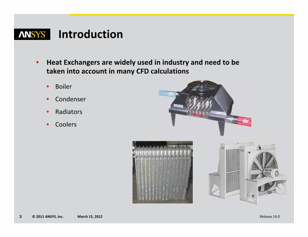
• Heat Exchangers are widely used in industry and need to be taken into account in many CFD calculations
• Boiler
• Condenser
• Radiators
• Coolers
© 2011 ANSYS, Inc. March 15, 20124 Release 14.0
Introduction
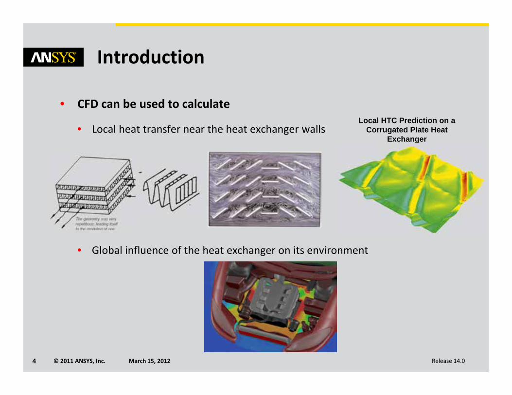
• CFD can be used to calculate
• Local heat transfer near the heat exchanger walls
• Global influence of the heat exchanger on its environment
Local HTC Prediction on a Corrugated Plate Heat
Exchanger
© 2011 ANSYS, Inc. March 15, 20125 Release 14.0
Introduction
• Heat exchanger geometries are generally complex and cannot be included in the CFD domain due to widely varying spatial length scales.
• Many difficulties will be alleviated if models were available to compute:
• Pressure loss generated by the heat exchanger for the primary flow
• Heat transfer between the primary and auxiliary flows
© 2011 ANSYS, Inc. March 15, 20126 Release 14.0
Outline
• Introduction
• Simulation of Heat Exchangers
• Heat Exchanger Models in FLUENT 14
• Other Heat Exchanger Models
• Summary
© 2011 ANSYS, Inc. March 15, 20127 Release 14.0
Simulation of Heat Exchangers
• Multiple models are available to simulate heat exchangers.
• Models range from very simple to very complex.
• Radiator model• Surface zone• Specific condition built‐in• Global pressure loss and heat transfer calculation• User input – pressure loss coefficient, heat transfer coefficient, radiator
temperature or heat flux
• Porous Media + Energy Source for fluid zone• Volume zone (fluid)• Non specific to heat exchanger• UDF can be used to defined velocity, position or time dependent profile• Refer to lecture on Heat Transfer in Porous Media
© 2011 ANSYS, Inc. March 15, 20128 Release 14.0
Outline
• Introduction
• Simulation of Heat Exchangers
• Heat Exchanger Models in FLUENT 14
• Other Heat Exchanger Models
• Summary
© 2011 ANSYS, Inc. March 15, 20129 Release 14.0
Simulation of Heat Exchangers
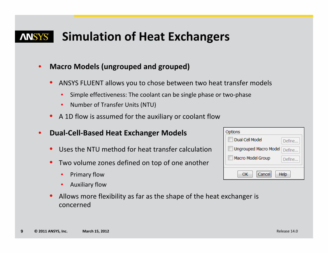
• Macro Models (ungrouped and grouped)
• ANSYS FLUENT allows you to chose between two heat transfer models• Simple effectiveness: The coolant can be single phase or two‐phase• Number of Transfer Units (NTU)
• A 1D flow is assumed for the auxiliary or coolant flow
• Dual‐Cell‐Based Heat Exchanger Models
• Uses the NTU method for heat transfer calculation
• Two volume zones defined on top of one another• Primary flow• Auxiliary flow
• Allows more flexibility as far as the shape of the heat exchanger is concerned
© 2011 ANSYS, Inc. March 15, 201210 Release 14.0
Macro Heat Exchanger Models Overview
• Auxiliary fluid temperature in heat exchanger is stratified.
• The “coolant” is referred to as the “auxiliary fluid.”
• Heat rejection not constant over the core
• Heat exchanger split into macroscopic cells or “macros” to account for non‐constant heat rejection
• The primary flow is unidirectional and must be aligned with one of the three orthogonal axes defined by the rectangular core
• Auxiliary fluid flow rate is assumed to be one‐dimensional.
© 2011 ANSYS, Inc. March 15, 201211 Release 14.0
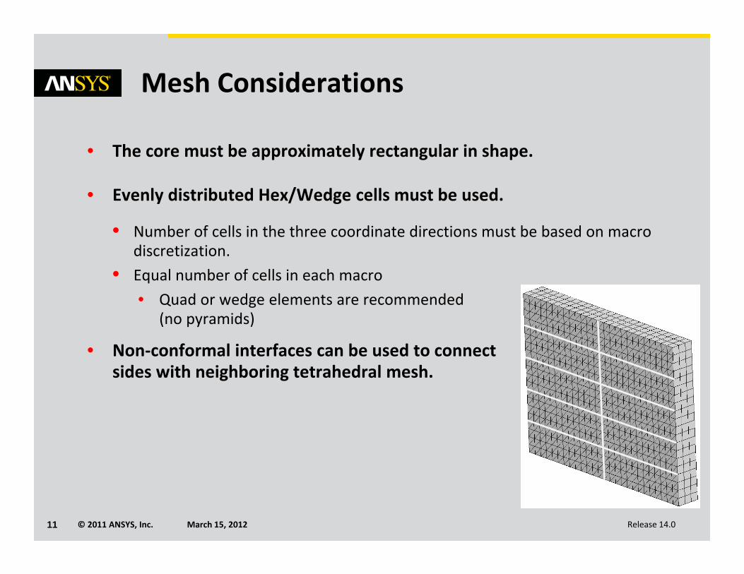
Mesh Considerations
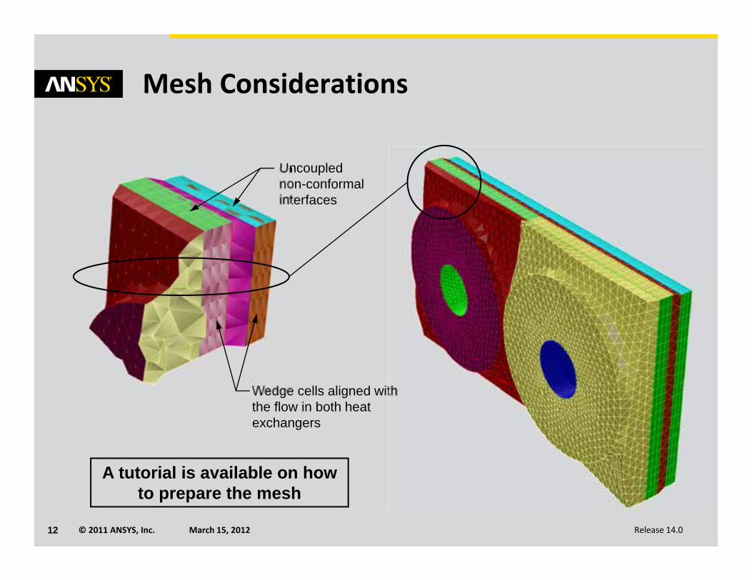
• The core must be approximately rectangular in shape.
• Evenly distributed Hex/Wedge cells must be used.
• Number of cells in the three coordinate directions must be based on macro discretization.
• Equal number of cells in each macro• Quad or wedge elements are recommended
(no pyramids)
• Non‐conformal interfaces can be used to connectsides with neighboring tetrahedral mesh.
© 2011 ANSYS, Inc. March 15, 201212 Release 14.0
Uncouplednon-conformalinterfaces
Mesh Considerations
Wedge cells aligned with the flow in both heat exchangers
A tutorial is available on how to prepare the mesh
© 2011 ANSYS, Inc. March 15, 201213 Release 14.0
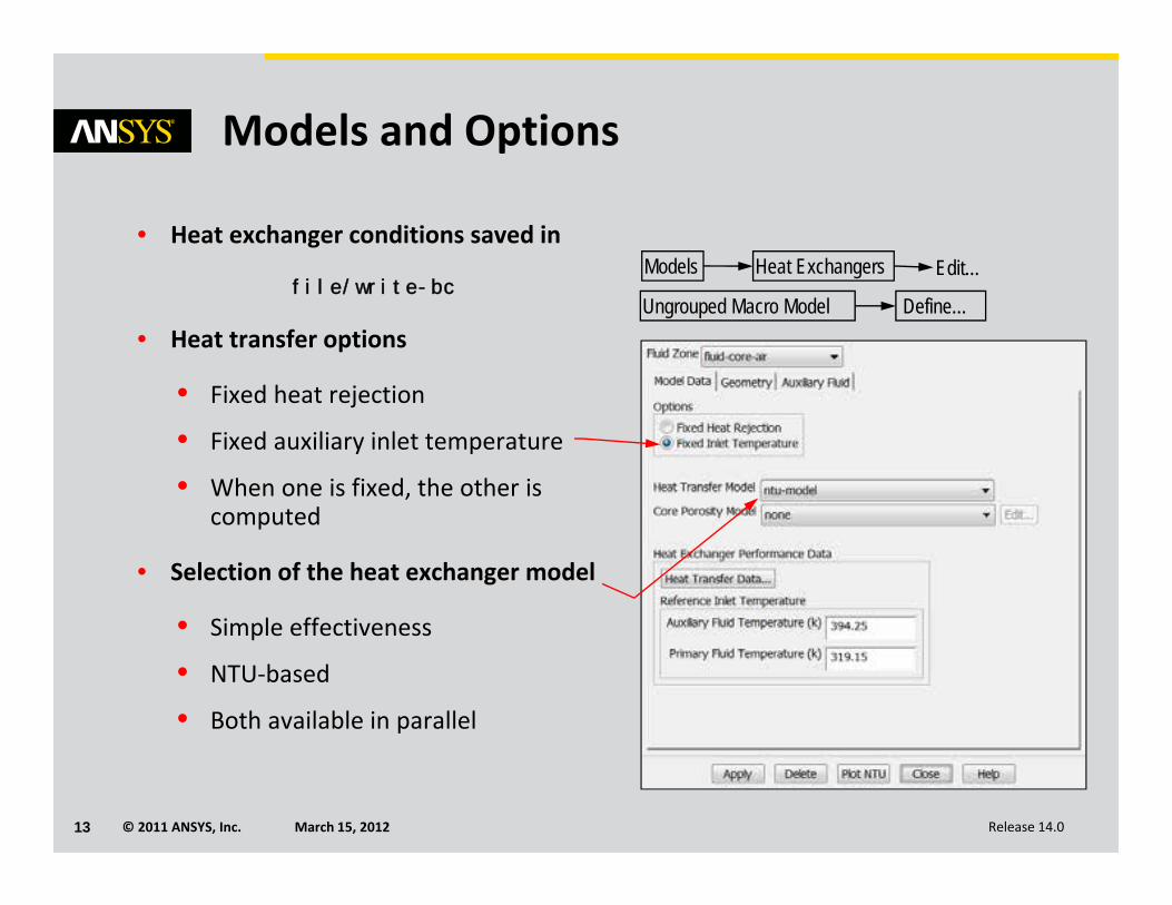
Models and Options
• Heat exchanger conditions saved in
file/write-bc
• Heat transfer options
• Fixed heat rejection
• Fixed auxiliary inlet temperature
• When one is fixed, the other is computed
• Selection of the heat exchanger model
• Simple effectiveness
• NTU‐based
• Both available in parallel
Models Edit…Heat Exchangers
Ungrouped Macro Model Define…
© 2011 ANSYS, Inc. March 15, 201214 Release 14.0
Simple Effectiveness Model
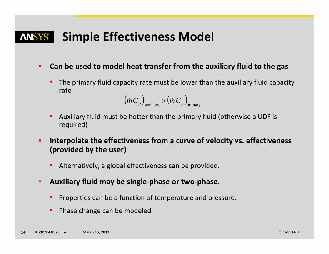
• Can be used to model heat transfer from the auxiliary fluid to the gas
• The primary fluid capacity rate must be lower than the auxiliary fluid capacity rate
• Auxiliary fluid must be hotter than the primary fluid (otherwise a UDF is required)
• Interpolate the effectiveness from a curve of velocity vs. effectiveness (provided by the user)
• Alternatively, a global effectiveness can be provided.
• Auxiliary fluid may be single‐phase or two‐phase.
• Properties can be a function of temperature and pressure.
• Phase change can be modeled.
primaryauxiliary pp CmCm
© 2011 ANSYS, Inc. March 15, 201215 Release 14.0
Simple Effectiveness Model
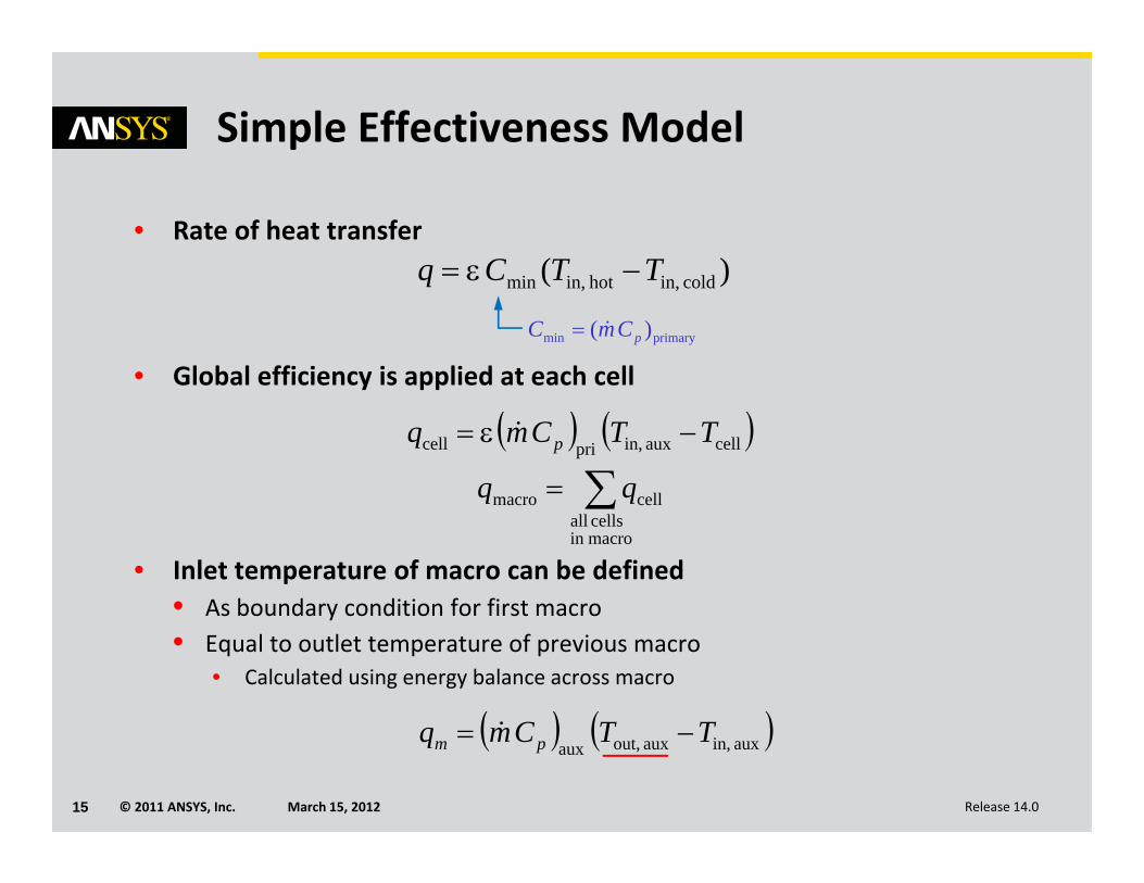
• Rate of heat transfer
• Global efficiency is applied at each cell
• Inlet temperature of macro can be defined• As boundary condition for first macro• Equal to outlet temperature of previous macro
• Calculated using energy balance across macro
)( cold in,hot in,min TTCq
primarymin )( pCmC
cellaux in,pricell TTCmq p
macroin cells all
cellmacro qq
aux in,aux out,auxTTCmq pm
© 2011 ANSYS, Inc. March 15, 201216 Release 14.0
NTU‐Based Model
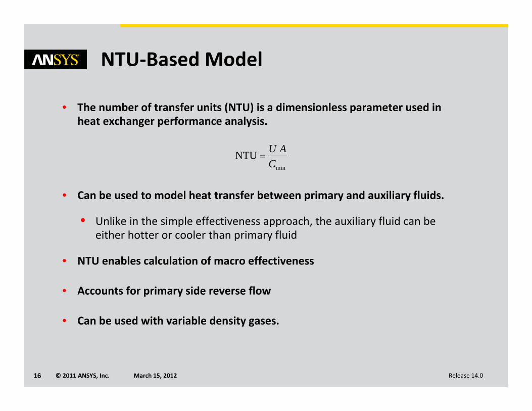
• The number of transfer units (NTU) is a dimensionless parameter used in heat exchanger performance analysis.
• Can be used to model heat transfer between primary and auxiliary fluids.
• Unlike in the simple effectiveness approach, the auxiliary fluid can be either hotter or cooler than primary fluid
• NTU enables calculation of macro effectiveness
• Accounts for primary side reverse flow
• Can be used with variable density gases.
min
NTUC
AU
© 2011 ANSYS, Inc. March 15, 201217 Release 14.0
NTU‐based Model
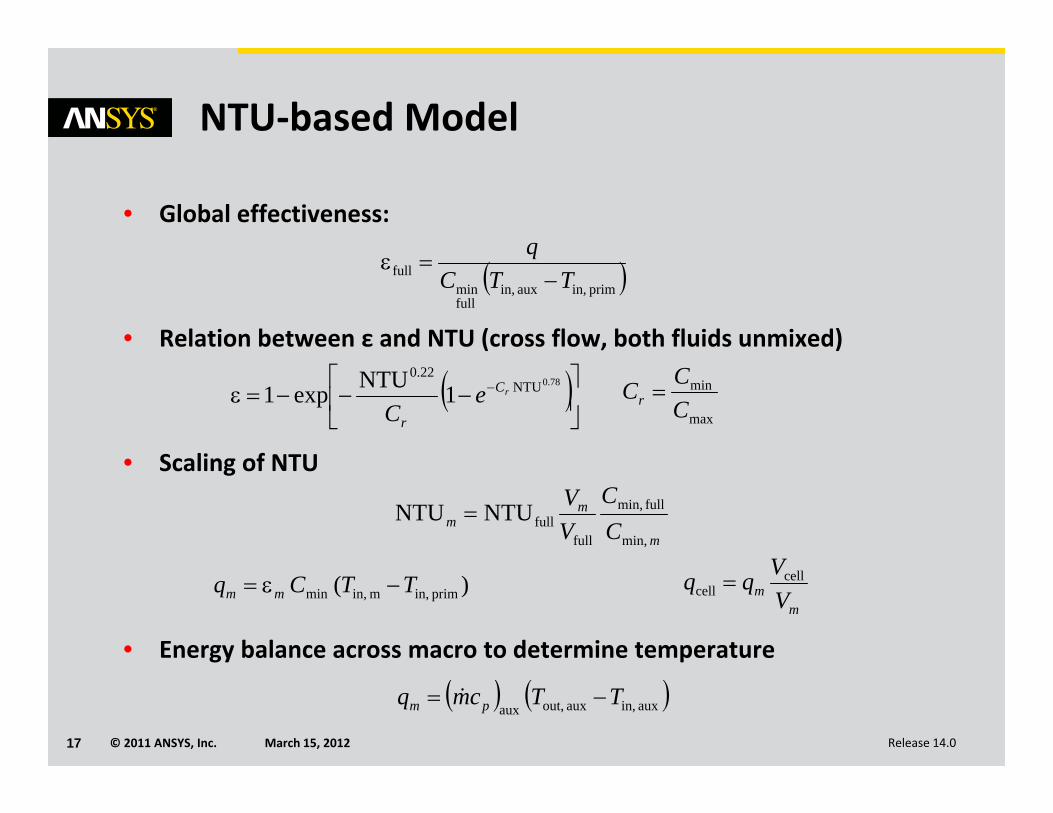
• Global effectiveness:
• Relation between ε and NTU (cross flow, both fluids unmixed)
• Scaling of NTU
• Energy balance across macro to determine temperature
78.0NTU
22.0
1NTUexp1 rC
r
eC max
min
CCCr
m
mm C
CVV
min,
full min,
fullfullNTUNTU
)( prim in,m in,min TTCq mm m
m VVqq cell
cell
prim in,aux in,fullmin
full TTCq
aux in,aux out,auxTTcmq pm
© 2011 ANSYS, Inc. March 15, 201218 Release 14.0
Core Porosity Model
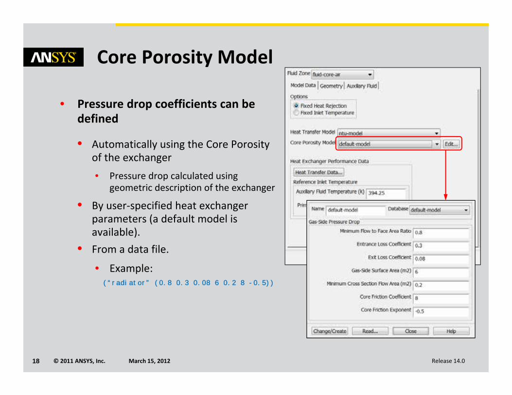
• Pressure drop coefficients can be defined
• Automatically using the Core Porosity of the exchanger• Pressure drop calculated using
geometric description of the exchanger
• By user‐specified heat exchanger parameters (a default model is available).
• From a data file.
• Example:(“radiator” (0.8 0.3 0.08 6 0.2 8 -0.5))
© 2011 ANSYS, Inc. March 15, 201219 Release 14.0
Automatic Core Porosity Model
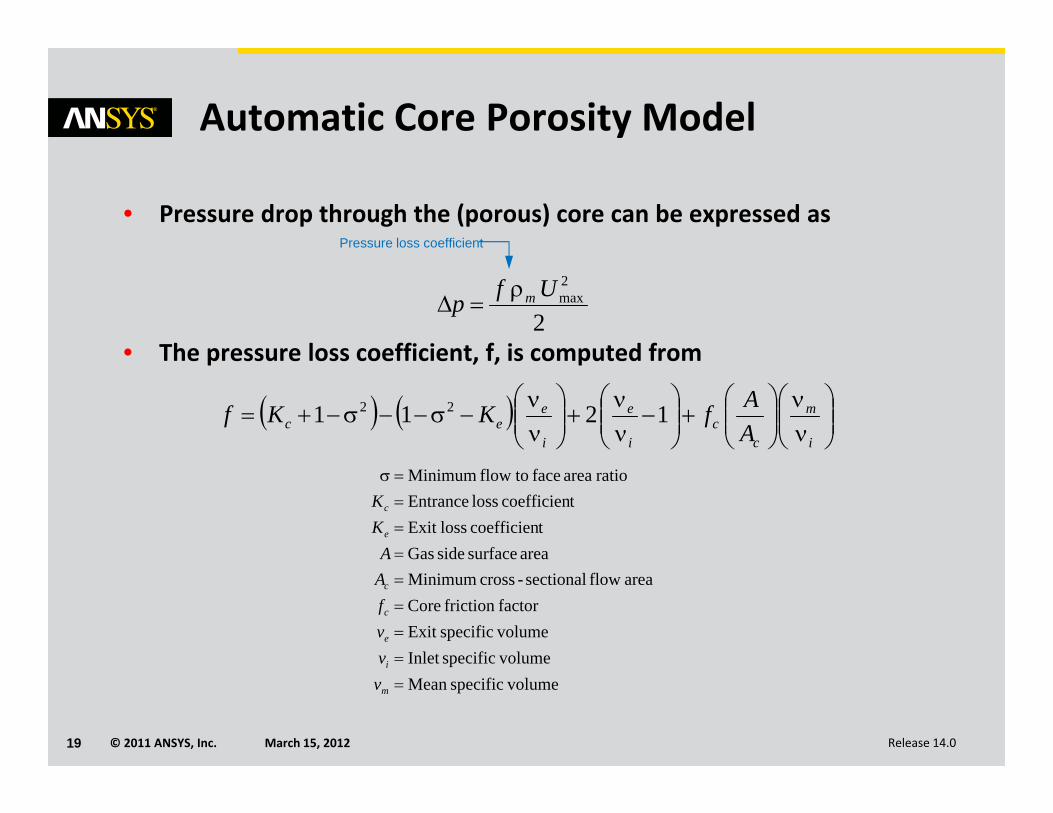
• Pressure drop through the (porous) core can be expressed as
• The pressure loss coefficient, f, is computed from
i
m
cc
i
e
i
eec A
AfKKf 1211 22
2
2maxUfp m
Pressure loss coefficient
volumespecificMean volumespecificInlet volumespecificExit factorfriction Core
area flow sectional-cross Minimumarea surface side Gas
tcoefficien lossExit tcoefficien loss Entrance
ratioareafacetoflowMinimum
m
i
e
c
c
e
c
vvvfAA
KK
© 2011 ANSYS, Inc. March 15, 201220 Release 14.0
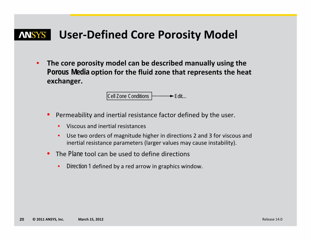
User‐Defined Core Porosity Model
• The core porosity model can be described manually using the Porous Media option for the fluid zone that represents the heat exchanger.
• Permeability and inertial resistance factor defined by the user.• Viscous and inertial resistances • Use two orders of magnitude higher in directions 2 and 3 for viscous and
inertial resistance parameters (larger values may cause instability).
• The Plane tool can be used to define directions• Direction 1 defined by a red arrow in graphics window.
Edit…Cell Zone Conditions
© 2011 ANSYS, Inc. March 15, 201221 Release 14.0
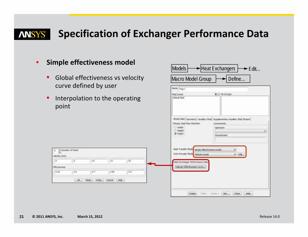
Specification of Exchanger Performance Data
• Simple effectiveness model
• Global effectiveness vs velocity curve defined by user
• Interpolation to the operating point
Models Edit…Heat Exchangers
Macro Model Group Define…
© 2011 ANSYS, Inc. March 15, 201222 Release 14.0
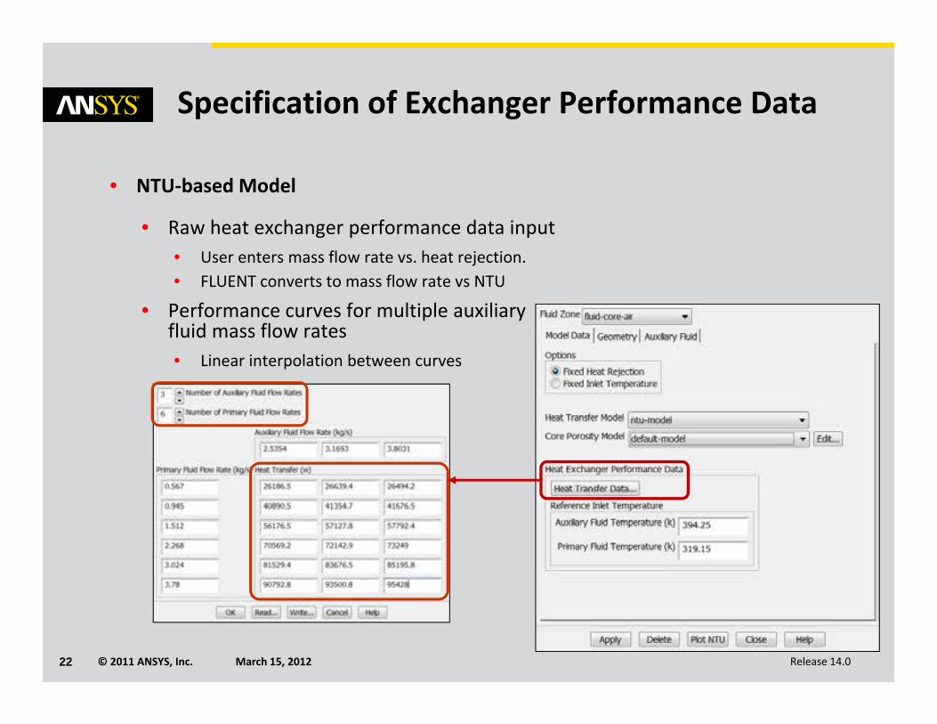
Specification of Exchanger Performance Data
• NTU‐based Model
• Raw heat exchanger performance data input• User enters mass flow rate vs. heat rejection.• FLUENT converts to mass flow rate vs NTU
• Performance curves for multiple auxiliary fluid mass flow rates• Linear interpolation between curves
© 2011 ANSYS, Inc. March 15, 201223 Release 14.0
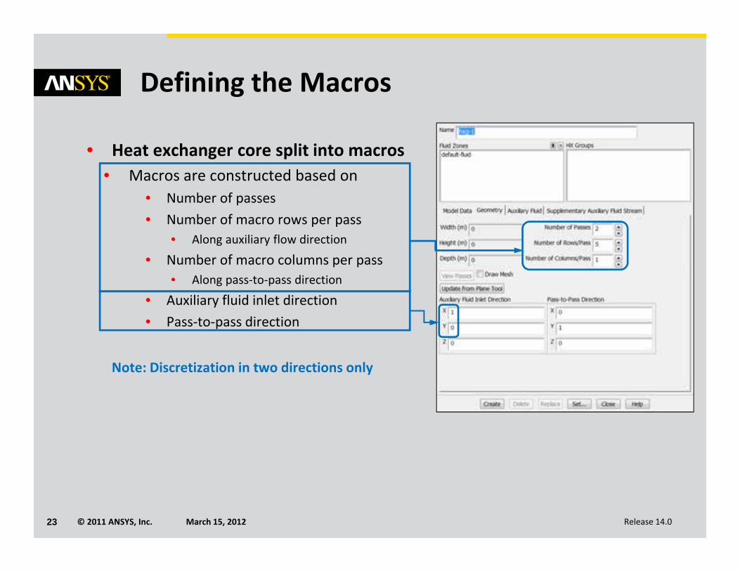
Defining the Macros
• Heat exchanger core split into macros• Macros are constructed based on
• Number of passes• Number of macro rows per pass
• Along auxiliary flow direction
• Number of macro columns per pass• Along pass‐to‐pass direction
• Auxiliary fluid inlet direction• Pass‐to‐pass direction
Note: Discretization in two directions only
© 2011 ANSYS, Inc. March 15, 201224 Release 14.0
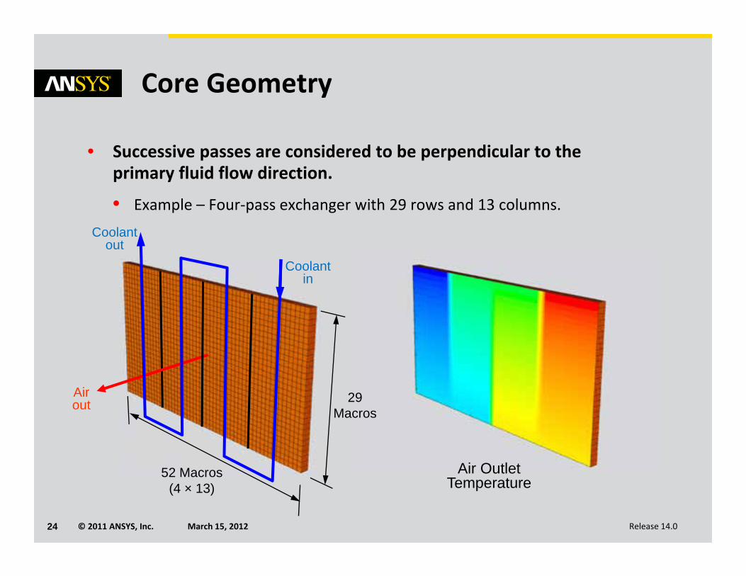
Core Geometry
• Successive passes are considered to be perpendicular to the primary fluid flow direction.
• Example – Four‐pass exchanger with 29 rows and 13 columns.
Coolant in
Coolant out
29Macros
52 Macros(4 × 13)
Air out
Air Outlet Temperature
© 2011 ANSYS, Inc. March 15, 201225 Release 14.0
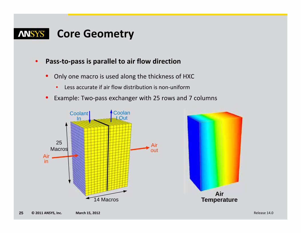
Core Geometry
• Pass‐to‐pass is parallel to air flow direction
• Only one macro is used along the thickness of HXC• Less accurate if air flow distribution is non‐uniform
• Example: Two‐pass exchanger with 25 rows and 7 columns
Air Temperature
Coolant In
Coolant Out
Air in
Air out
14 Macros
25Macros
© 2011 ANSYS, Inc. March 15, 201226 Release 14.0
Core Geometry
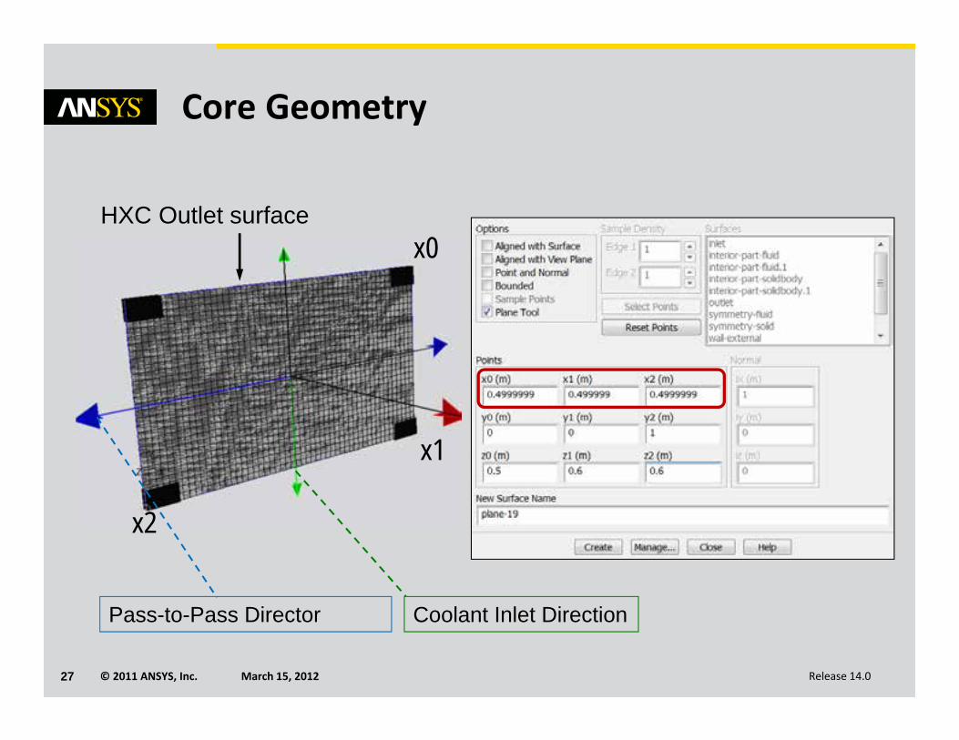
• Coolant Inlet Direction and Pass‐to‐Pass Direction can be defined using the Plane Tool (if the core is not aligned with coordinate directions).
• Plane tool setup
• Open Surface / Plane panel
• Select three points to define the exchanger outlet plane• x0 to x1 : coolant inlet flow direction
• Green arrow of the plane tool
• x1 to x2 : pass‐to‐pass direction• Blue arrow of the plane tool
• Click on Plane Tool option to define it.
• Define core geometry by clicking Update from Plane Tool in Heat Exchanger panel
© 2011 ANSYS, Inc. March 15, 201227 Release 14.0
x0
x1
x2
Coolant Inlet DirectionPass-to-Pass Director
Core Geometry
HXC Outlet surface
© 2011 ANSYS, Inc. March 15, 201228 Release 14.0
Core Geometry
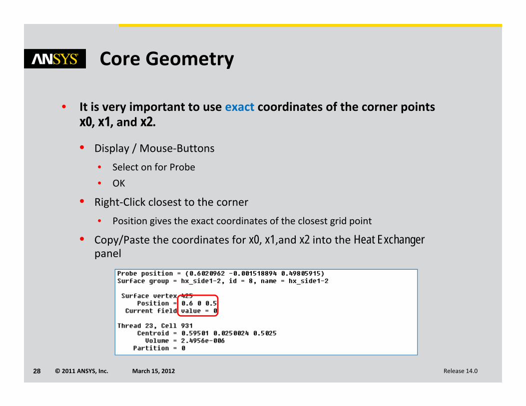
• It is very important to use exact coordinates of the corner points x0, x1, and x2.
• Display / Mouse‐Buttons• Select on for Probe• OK
• Right‐Click closest to the corner• Position gives the exact coordinates of the closest grid point
• Copy/Paste the coordinates for x0, x1,and x2 into the Heat Exchanger panel
© 2011 ANSYS, Inc. March 15, 201229 Release 14.0
Auxiliary Fluid
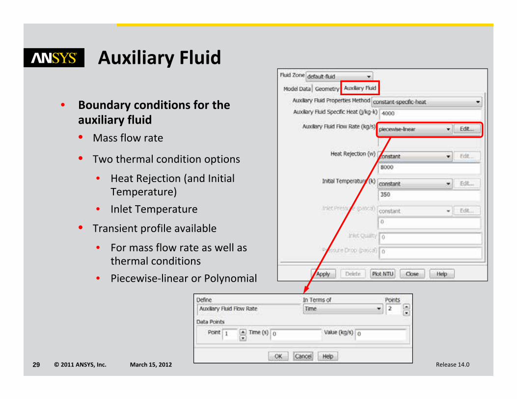
• Boundary conditions for the auxiliary fluid• Mass flow rate
• Two thermal condition options
• Heat Rejection (and Initial Temperature)
• Inlet Temperature
• Transient profile available
• For mass flow rate as well as thermal conditions
• Piecewise‐linear or Polynomial
© 2011 ANSYS, Inc. March 15, 201230 Release 14.0
Auxiliary Fluid
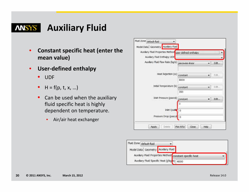
• Constant specific heat (enter the mean value)
• User‐defined enthalpy• UDF
• H = f(p, t, x, …)
• Can be used when the auxiliary fluid specific heat is highly dependent on temperature.• Air/air heat exchanger
© 2011 ANSYS, Inc. March 15, 201231 Release 14.0
Heat Exchanger Group
• Ability to group Heat Exchangers together
• In parallel
• In series
• Compatible with both simple‐effectiveness and NTU‐based models
• No need to define heat exchangers from fluid zones before defining heat exchanger groups
• The complete setup can be done in the same panel
• When using groups, fixed inlet temperature is the only heat transfer option available.
© 2011 ANSYS, Inc. March 15, 201232 Release 14.0
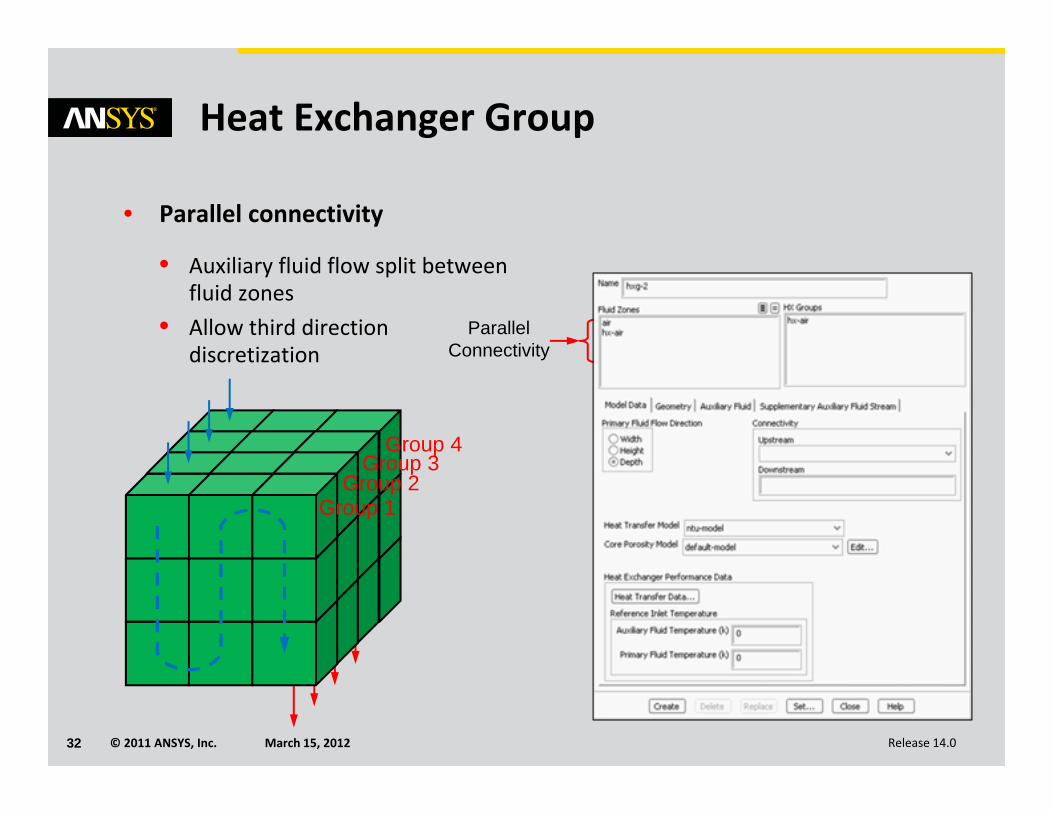
Heat Exchanger Group
• Parallel connectivity
• Auxiliary fluid flow split between fluid zones
• Allow third direction discretization
ParallelConnectivity
Group 1Group 2
Group 3Group 4
© 2011 ANSYS, Inc. March 15, 201233 Release 14.0
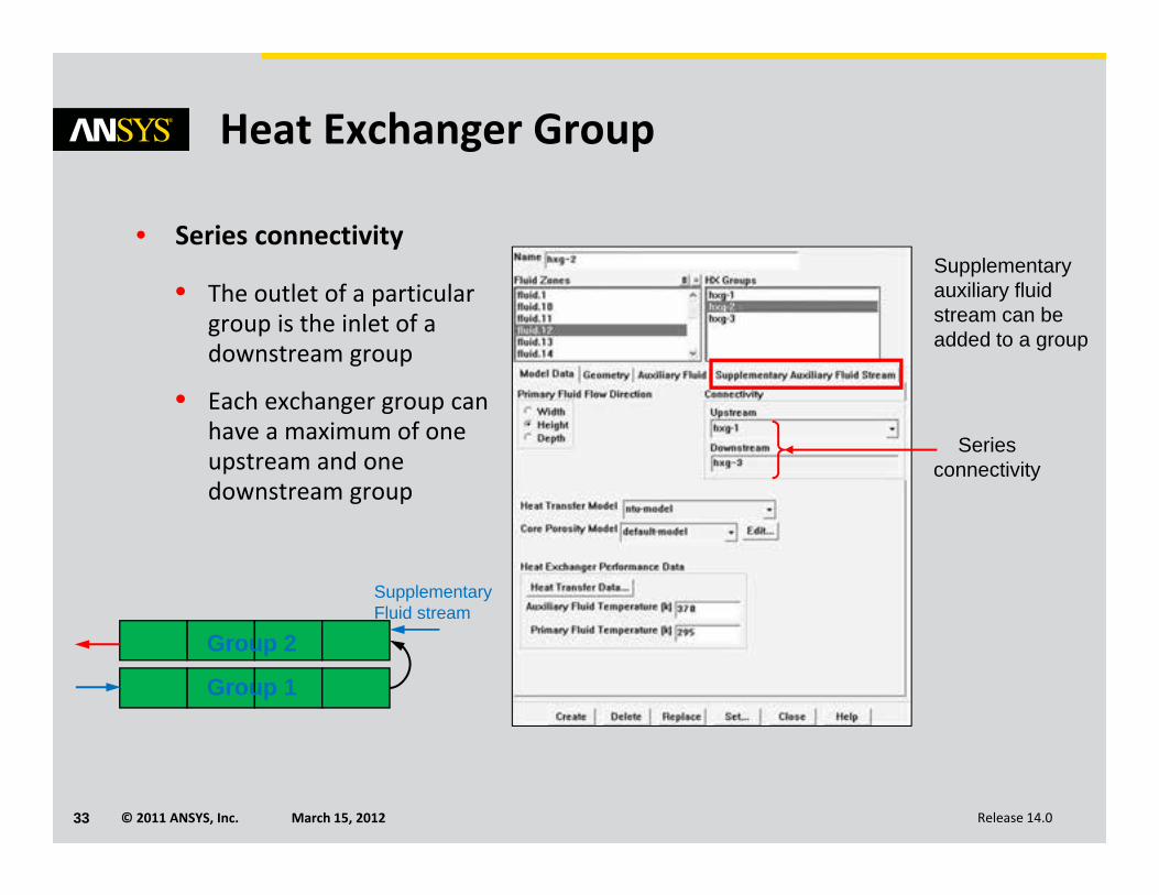
Heat Exchanger Group
• Series connectivity
• The outlet of a particular group is the inlet of a downstream group
• Each exchanger group can have a maximum of one upstream and one downstream group
Series connectivity
Supplementary auxiliary fluid stream can be added to a group
Group 1
Group 2
SupplementaryFluid stream
© 2011 ANSYS, Inc. March 15, 201234 Release 14.0
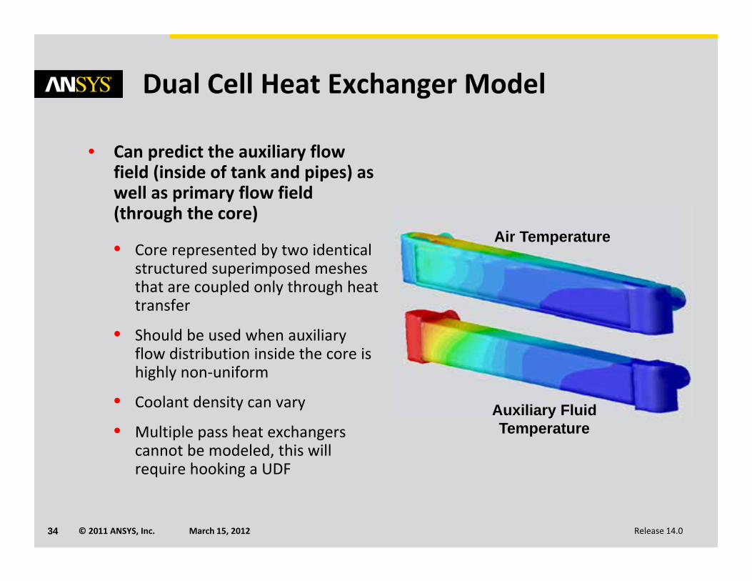
Dual Cell Heat Exchanger Model
• Can predict the auxiliary flow field (inside of tank and pipes) as well as primary flow field (through the core)
• Core represented by two identical structured superimposed meshes that are coupled only through heat transfer
• Should be used when auxiliary flow distribution inside the core is highly non‐uniform
• Coolant density can vary
• Multiple pass heat exchangers cannot be modeled, this will require hooking a UDF
Air Temperature
Auxiliary FluidTemperature
© 2011 ANSYS, Inc. March 15, 201235 Release 14.0
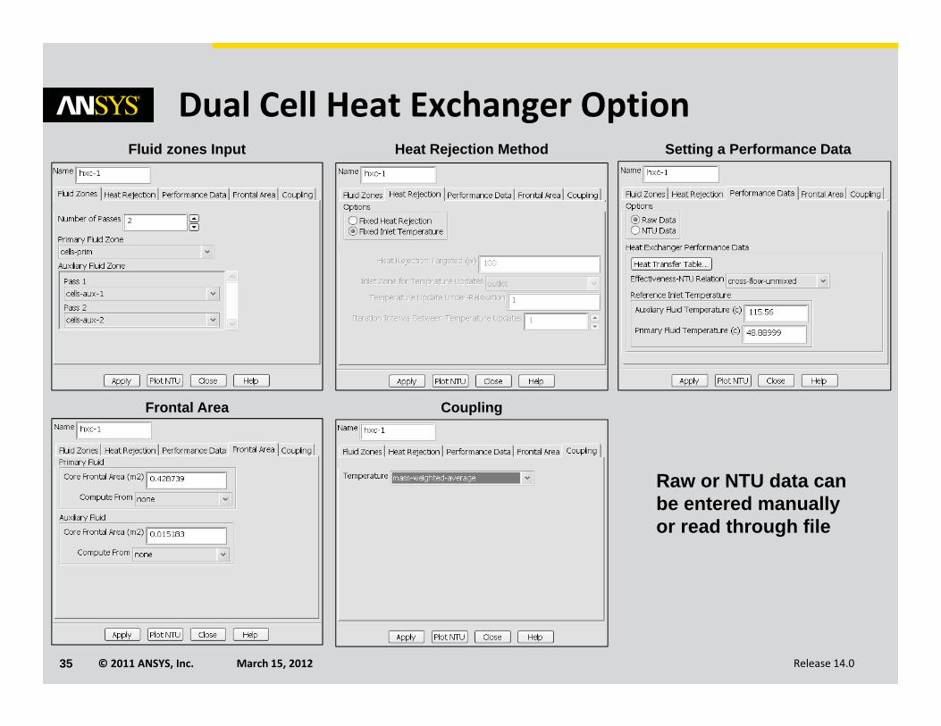
Dual Cell Heat Exchanger OptionFluid zones Input Heat Rejection Method Setting a Performance Data
Frontal Area Coupling
Raw or NTU data can be entered manually or read through file
© 2011 ANSYS, Inc. March 15, 201236 Release 14.0
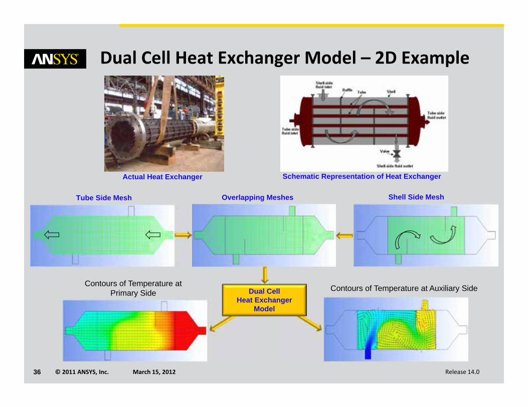
Dual Cell Heat Exchanger Model – 2D Example
Actual Heat Exchanger Schematic Representation of Heat Exchanger
Tube Side Mesh Shell Side Mesh
Dual Cell Heat Exchanger
Model
Overlapping Meshes
Contours of Temperature at Primary Side Contours of Temperature at Auxiliary Side
© 2011 ANSYS, Inc. March 15, 201237 Release 14.0
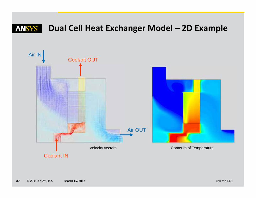
Dual Cell Heat Exchanger Model – 2D Example
Air IN
Air OUT
Coolant OUT
Velocity vectors Contours of Temperature
Coolant IN
© 2011 ANSYS, Inc. March 15, 201238 Release 14.0
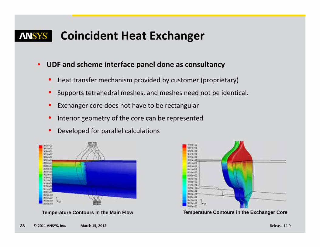
Coincident Heat Exchanger
• UDF and scheme interface panel done as consultancy
• Heat transfer mechanism provided by customer (proprietary)
• Supports tetrahedral meshes, and meshes need not be identical.
• Exchanger core does not have to be rectangular
• Interior geometry of the core can be represented
• Developed for parallel calculations
Temperature Contours In the Main Flow Temperature Contours in the Exchanger Core
© 2011 ANSYS, Inc. March 15, 201239 Release 14.0
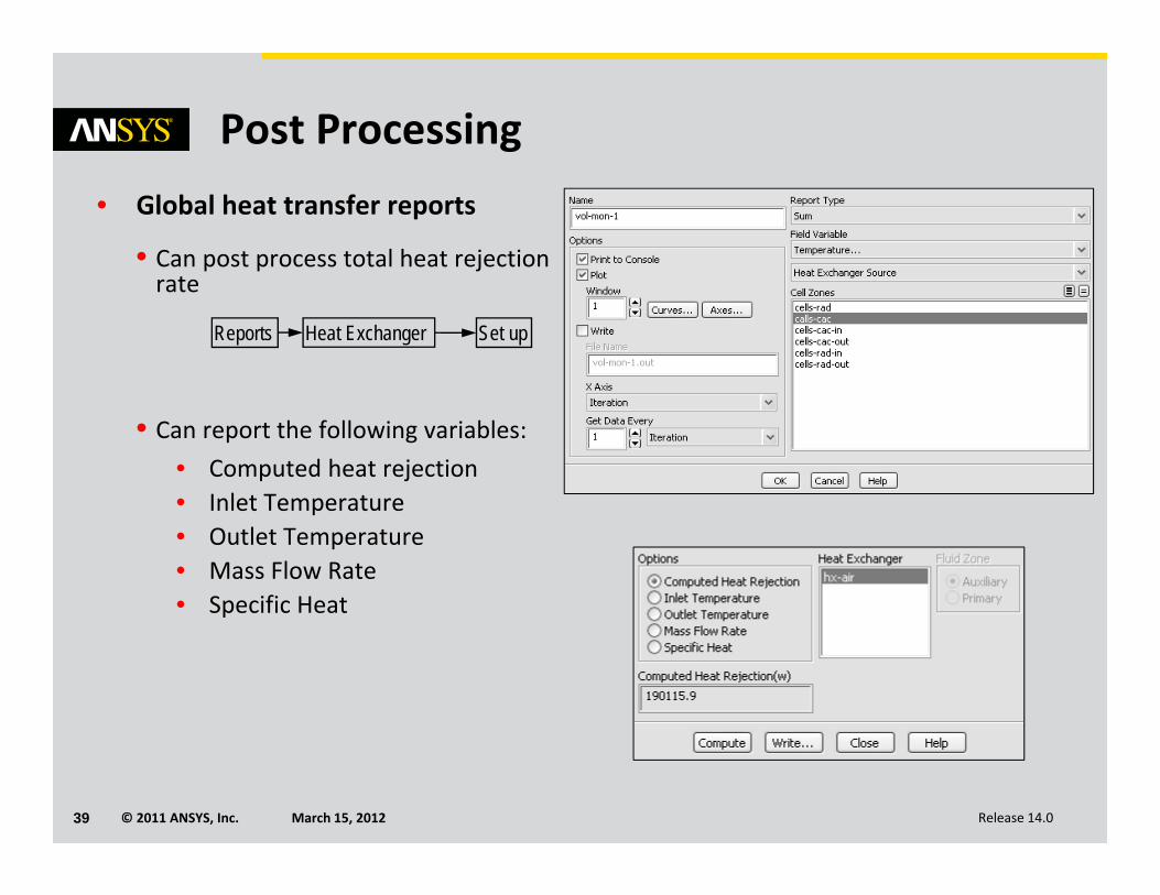
Post Processing• Global heat transfer reports
• Can post process total heat rejection rate
• Can report the following variables:• Computed heat rejection• Inlet Temperature• Outlet Temperature• Mass Flow Rate• Specific Heat
Reports Heat Exchanger Set up