Embed Size (px)
Citation preview

Microwave plasma activation of a polyvinylidene fluoride surface for protein immobilization
This article has been downloaded from IOPscience. Please scroll down to see the full text article.
2011 J. Phys. D: Appl. Phys. 44 475303
(http://iopscience.iop.org/0022-3727/44/47/475303)
Download details:
IP Address: 130.209.6.41
The article was downloaded on 05/04/2012 at 14:58
Please note that terms and conditions apply.
View the table of contents for this issue, or go to the journal homepage for more
Home Search Collections Journals About Contact us My IOPscience
IOP PUBLISHING JOURNAL OF PHYSICS D: APPLIED PHYSICS
J. Phys. D: Appl. Phys. 44 (2011) 475303 (15pp) doi:10.1088/0022-3727/44/47/475303
Microwave plasma activation of apolyvinylidene fluoride surface for proteinimmobilizationC Vasile1,5, M C Baican2, C M Tibirna3, C Tuchilus2, D Debarnot4,E Paslaru1 and F Poncin-Epaillard4
1 ‘P. Poni’ Institute of Macromolecular Chemistry, 41A Gr. Ghica Voda Alley, 700487 Iasi, Romania2 ‘Gr. T. Popa’ Medicine and Pharmacy University, 16 University Str., 700115 Iasi, Romania3 Departement de Genie Chimique, Faculte de Sciences et Genie, Laval University, Quebec, Canada4 Laboratoire Polymeres, Colloıdes et Interfaces, UMR 6120 CNRS-Universite du Maine av. O.Messiaen, 72000 Le Mans, France
E-mail: [email protected], [email protected], m [email protected], [email protected],[email protected], [email protected] [email protected]
Received 11 July 2011, in final form 21 September 2011Published 8 November 2011Online at stacks.iop.org/JPhysD/44/475303
AbstractPolyvinylidene fluoride (PVDF) was modified by CO2, N2 or N2/H2 plasmas, which permittedthe attachment of short carboxyl or amino groups. A variation of the discharge parameters wasperformed, for their optimization, as well as for minimizing degradation in favour of acidic,amphiphilic or basic functionalization, respectively. The optimum parameters of discharge forCO2, N2 or N2/H2 plasmas were P = 50 W, gas flow rate Q = 16 × 10−8 m3 s−1, exposuretime t = 30–60 s, d = 0.1 m, pressure 15 Pa. The new surfaces were characterized bywettability measurements, attenuated total reflectance-Fourier transform infrared spectroscopy(ATR-FTIR), x-ray photoelectron spectroscopy (XPS) and atomic force microscopy (AFM)methods. In a second step, the proteins (triglycine (TG) and protein A) were adsorbed orchemically grafted onto the carboxyl or amino functionalized surface, after EDC/NHS(1-ethyl-3-(-dimethylaminopropyl) carbodiimide/N -hydroxysuccinimide) activation ofproteins. ATR-FTIR, XPS and AFM investigations confirmed the presence of protein on thesurface. The XPS C1s core levels at 286.3 eV (C–N), 288 eV (amide bond) and 298 eV(carboxylic acid), together with variation of the O1s and N1s signals, illustrated theimmobilization of proteins. It was established that TG was better attached on surfacesactivated with N2/H2 plasma, while protein A was more tightly anchored on CO2, N2
plasma-activated surfaces. The former procedure allowed higher surface densities, while thelatter permitted a better chemical control. The results proved that plasma-treated PVDF is agood substrate for protein coating, which can be further used for microorganisms’ detection, asevidenced by the immunoassay test.
(Some figures may appear in colour only in the online journal)
1. Introduction
Recently, modification of the surface properties of polymershas become a topic of special interest for numerous researchers.The two usually applied procedures, referred to as physical and
5 Author to whom any correspondence should be addressed.
chemical methods, aim at modifying the surface properties ofpolymers. However, the chemical method is a water-wastingprocess and easily causes environment pollution. In contrast,physical methods have been preferred in recent years, due totheir cleanness and high efficiency [1]. Therefore, plasma-surface modification can induce a specific surface chemistry,
0022-3727/11/475303+15$33.00 1 © 2011 IOP Publishing Ltd Printed in the UK & the USA

J. Phys. D: Appl. Phys. 44 (2011) 475303 C Vasile et al
without altering the bulk properties of the material [2]. Sinceplasma is a dry process, there are no disposal or personnelsafety issues commonly associated with wet chemistry or withother conventional methods, such as flame treatment. Inherentcleanliness and the ability to automate and control all criticalfunctions of the processing make the treatment especiallyattractive for clean manufacturing environment.
Polymer-surface modification by a discharge plasma isexpected to have increasingly important industrial applications[3]. Numerous experimental and theoretical studieshave been devoted to this topic in recent years. Forexample, Liu et al [4] reported that examination of pre-and post-plasma-treated polymer surfaces by atomic forcemicroscopy (AFM) revealed that only the outermost layerwas affected by the dielectric barrier discharge (DBD)plasma treatment. Guruvenket et al [5] modified polystyreneand polyethylene (PE) using microwave (MW) electroncyclotron resonance plasma, to improve surface wettability.Bhowmik et al [6] studied the wettability and physico-chemical characteristics of a polypropylene (PP) film exposedto a dc glow discharge. Coen et al [7] and Akishevet al [8] modified PP, polymethylmethacrylate (PMMA),polytetrafluoroethylene (PTFE) and polyethyleneterephthalate(PET) under cold plasma conditions. Vesel [9] functionalizedPET in both oxygen and CO2 plasmas, finding differencesonly for extremely short treatment times. These surfacemodifications include surface cleaning and degreasing,topographical modification, oxidation, reduction, grafting,cross-linking (carbonization), etching and deposition. Whentrying to achieve targeted surface engineering mainly forbiomedical applications, it is vital to gain full understandingof the mechanisms that cause these effects, for example,surface functionalization, adhesion promotion or multi-layerdeposition [10, 11].
Reactive plasmas are often created in flowing gases (toensure a fast removal of the plasma-surface reaction products),in electrodeless discharges, such as inductively coupledradiofrequency (RF) discharges and microwave discharges(MDs) [12]. A MW plasma can be generated at pressures from10−3 Pa up to atmospheric pressure in pulse and continuumwave regimes, at incident powers ranging between severalwatts and hundreds of kW. Nowadays, MDs are widely usedfor the generation of quasi-equilibrium and non-equilibriumplasmas for different applications, such as generation of anactive medium in gas discharge lasers, light sources, in plasmachemistry, analytical chemistry etc [13].
Use of a MW plasma offers some advantages. It typicallytakes place between ambient temperature and 50 ◦C. Thisphenomenon is due to the fact that, despite a low gastemperature, high electron temperatures are present, due tothe increased path length [14]. This allows processing of veryheat-sensitive plastics, such as balloon catheters or heat shrinktubing. The type of functionalization imparted can be varied bythe selection of plasma gas (Ar, N2, O2, H2O, CO2, NH3) andby the operating parameters (pressure, power, time, gas flowrate) [15]. Since treatments occur in vacuum in a preciselycontrolled environment, the results are reproducible.
Immobilization of proteins onto polymer surfaces is ofconsiderable interest for numerous applications, particularly
in developing medical implant materials [16], bioseparators[17], biosensors [18], etc. Therefore, much effort has beenmade to develop methods of protein immobilization [19].One of the most interesting ways is the modification ofpolymers by grafting techniques, with subsequent physicalor covalent immobilization of proteins [20]. Methodsfor the immobilization of biological compounds includeadsorption, cross-linking, covalent bonding, entrapment andencapsulation. The most common methods applied forthe immobilization of proteins are adsorption and covalentbonding [21].
A gas discharge in CO2 is characterized by an intensevacuum-ultraviolet irradiation, producing radicals in thesurface layer of PTFE [22], which can effectively react withthe active oxygen species during plasma treatment. This couldbe explained by the rapid dissociation of the CO2 molecule toneutral oxygen atoms, which are fairly stable in glass dischargetubes and readily react with the surface of polymer materialsand also with CO radicals [23].
Functionalization of PTFE for human thrombomodulinbinding has been achieved by CO2 plasma activation andsubsequent vapour phase graft polymerization of acrylic acid[24]. In our previous papers, surface modification of high-density polyethylene by a CO2 MW plasma with the aim offixing carboxylic groups is described. Formation of carboxylicacids seems favoured mainly by the presence of the CO2
active species [24, 25]. To minimize the degradation effecton the biomaterial surface (since the formation of a degradedlayer gives a weaker bond layer, which may induce proteinactivation), the atomic species such as oxygen atoms [26] inthe plasma should be eliminated. CO2 is less aggressive thanoxygen and safer under working conditions.
Some biomolecules were immobilized onto plasma-pretreated polyvinylidene fluoride (PVDF) surfaces usingdifferent methods. Lin et al [27] modified the surface ofthe PVDF membranes in two steps. First, poly(acrylicacid) (PAA) was grafted on PVDF membranes withvarious surface porosities by plasma-induced polymerization.Then, heparin was covalently bonded to PAA withthe aid of 1-ethyl-3 (3-dimethylaminopropyl)-carbodiimidehydrochloride) (EDAC). Young et al [28] modified the PVDFsurface by immobilization of L-lysine and 1,6-hexanediamine(HMDA). The membrane was first grafted with poly(glycidylmethacrylate) (PGMA), by means of plasma-induced freeradical polymerization. Then, L-lysine or HMDA was reactedwith the epoxy groups in the grafted PGMA.
In this work, PVDF was proposed as a support forprotein immobilization. The high hydrophobicity of PVDFrestrained it from promotion and application. To make thePVDF film hydrophilic, many studies focused on plasmatreatment [29]. The surface activation technique was aimed atcreating functional groups capable of preferential adsorptionof the biologically active species (proteins, enzymes, cells,drugs, etc). To this end, PVDF was subjected to successivesurface modifications by MW plasma activation (pretreatment)in different atmospheres (CO2, N2 and N2/H2), followed bycoating with proteins by both direct adsorption and grafting.
The objectives of this study were to optimize the dischargeparameters for surface functionalization using a CO2 MW
2

J. Phys. D: Appl. Phys. 44 (2011) 475303 C Vasile et al
plasma, and the immobilization procedures of some proteinson the treated surfaces. Study of protein immobilization on asurface functionalized by a CO2 MW plasma was performedcomparatively with the previously reported PVDF surfacefunctionalization by N2 and N2/H2 MW plasmas [30], toevidence the importance of the type of groups implanted onthe surface for the protein coating stage. Characterizationof the modified surfaces with respect to the unmodifiedone was done by different investigation methods, such ascontact angle measurements, x-ray photoelectron spectroscopy(XPS), attenuated total reflectance-Fourier transform infraredspectroscopy (ATR-FTIR) and AFM. Triglycine and proteinA have been selected for the study. The first one is a modelprotein with a short linear chain of three molecules of thesimplest amino acid glycine with two functionalities (aminoand carboxyl) [31], while protein A is originally found in thecell wall of the Staphylococcus aureus bacteria. Protein Ais able to selectively bind IgG, antigen-bound IgG and IgMcomplexes, such as rheumatoid factors and circulating immunecomplexes [32].
2. Experimental
2.1. Materials
Polyvinylidene fluoride films (PVDF) (0.25 mm thick,purchased from Goodfellow, UK). As already mentioned,a non-piezo-PVDF was used for setting up the surfacemodification protocol, since it has already been demonstratedthat the piezoelectric properties are not altered after treatmentunder optimal conditions [33].
Protein A (Sigma Chem) is a 42 kDa MSCRAMM andpI 5.3. Protein A is a single polypeptidic chain containing fourrepetitive domains rich in aspartic and glutamic acids free ofcysteine [34].
Triglycine (glycil-glycil-glycine), obtained as a powdersample from Sigma Aldrich, has the molecular formulaC6H11N2O4 and purity >99%.
2.2. Surface treatments
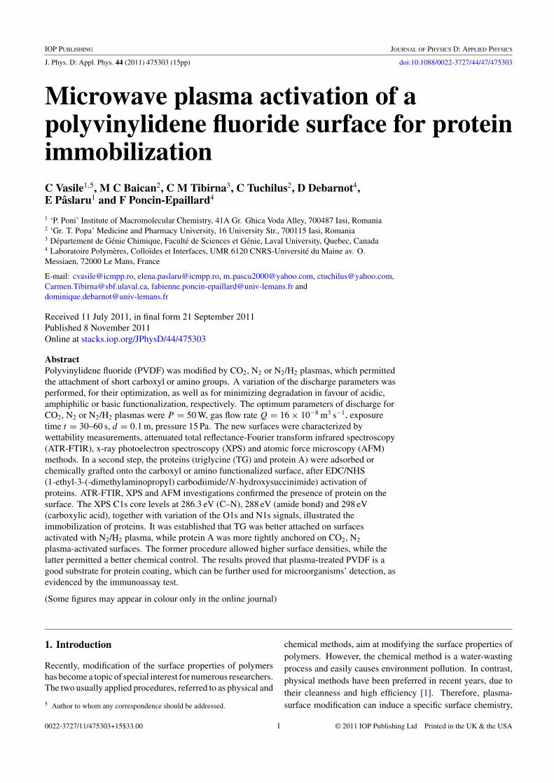
2.2.1. Plasma activation. Films of PVDF were treated ina MW plasma, using the experimental set-up presented infigure 1, and different discharge gases (i.e. CO2, N2 and N2/H2
1 : 3, purchased from Air Liquide France—Alphagaz; purityof N2, CO2 and H2 was 99.999%).
Plasma excitation is provided by a MW generator(SAIREM, 433 MHz), coupled to a resonant cavity (surfatron).A cylindrical MW plasma column is generated using thissurfatron. The incident power (Pi) and the reflected power (Pr)are measured with a power meter (Hewlett–Packard no 435B).Impedance is adjusted until the reflected power is very low (Pr:0.02 W). The glow is generated at the top of the reactor. Thepumping system is composed of primary (CIT Alcatel no 2012)and oil diffusion (CIT Alcatel Crystal) pumps. A MKS massflow meter (type 1259B) controlled the volume flow rate (Q).For a volume flow rate of 16×10−8 m3 s−1, the pressure is about20–30 Pa. The reactor is a quartz cylinder 500 mm in lengthand 76 mm in diameter. The reactor is set up on a chamber
Figure 1. Experimental set-up for microwave plasma treatment ofthe PVDF surface.
used for sample introduction. The substrate could be movedin or out of the plasma volume, to vary the distance (d in m)between the bottom of the excitation source and the sample.The sample holder allows us to locate the sample either indirect contact with a 2.45 GHz MW plasma, or downstream,where only the long-lived species (largely neutrals) from theplasma effluent contribute to the process chemistry.
The following parameters are varied: exposure time(t , 5–60 s), discharge power (P , 10–70 W), volume flow rate(Q, 8×10⁻⁸–50×10−8 m3 s−1), pressure (20–30 Pa), positionof the samples with respect to the surfatron (d, 2.5 × 10⁻²–15 × 10−2 m), allowing us to expose the samples both indischarge and post-discharge.
The optimal CO2 plasma parameters will be establishedhere, while those with N2 or N2/H2 plasmas were previouslydetermined [30]. In all cases, the composition of residualatmosphere, proved by optical emission spectroscopy (OES),was essentially constituted of water vapour and nitrogen, finalpressure being 10−4 Pa.
2.2.2. Physisorption of protein A and triglycine. Afterrinsing with ethanol, the PVDF film was plasma-treated, afterwhich a protein solution (10 µl of c = 2.5 mg ml−1) made ofprotein A or triglycine was spread over the entire surface andstored at 4 ◦C overnight (for at least 15 h). The excess proteinwas removed by rinsing with phosphate-buffered saline (PBS).
2.2.3. Grafting of protein A and triglycine. The untreatedand plasma-exposed surfaces were treated with 75mM EDC(1-ethyl-3-(-dimethylaminopropyl) carbodiimide) + 15mMNHS (N -hydroxysuccinimide) [35, 36] and protein (10 µl ofc = 2.5 mg ml−1) for 1 h, to convert the terminal carboxylicgroups by generation of a stable acyl amino ester intermediate.After condensation of proteins and aminolysis of NHS, theadduct was formed. The excess of protein was removed byrinsing with PBS (pH 7.4). Prior to analysis, all films werestored at 4 ◦C.
3
J. Phys. D: Appl. Phys. 44 (2011) 475303 C Vasile et al
2.3. Methods
2.3.1. Contact angle measurements. The contact anglesfor the polymer films were determined by the sessile dropmethod, at room temperature and controlled humidity, within30 s after placing 1 µl drops of liquids on the film surface[37, 38], using a CAM-200 instrument from KSV, Finland.The contact angles between three different pure liquids (onenon-polar: diiodomethane, and two polar: twice-distilled waterand formamide) and the polymer surface were determined.For obtaining the components of the free surface energy fromcontact angle measurements, the Young–Good–Girifalco–Fowkes theory was used and the Young complete equationwas applied [39]:
γL(1 + cos θ) = 2[(γ LWS γ LW
L )1/2 + (γ +S γ −
L )1/2 + (γ −S γ +
L )1/2]
(1)
where θ is the contact angle between the solid surface and theused liquid, γ LW the Lifshitz–van der Waals component of thefree surface energy, γ + and γ − the electron acceptor and theelectron donor components, respectively, of the free surfaceenergy; S and L stand for the solid surface and the liquid used,respectively.
The adhesion work (Wa), a thermodynamic parameterrelevant for the adsorption characteristics of the surface,controlling all interfacial events, was calculated using theYoung–Dupre equation [38]:
Wa = γLV(1 + cos θ) (2)
where θ is the contact angle and γLV is the surface tension ofthe liquid used for measurements. The subscript LV denotesthe interfacial liquid–vapour tension.
The interfacial tension between blood and the film surfacewas calculated using the following equation [37, 38]:
γSL = [(γ pL )1/2 − (γ
pS )1/2]2 + [(γ d
L )1/2 − (γ dS )1/2]2 (3)
where γ p and γ d are the polar and the dispersive componentsof the free surface energy, respectively; L and S stand for theliquid and the solid, respectively.
2.3.2. ATR-FTIR. The ATR-FTIR spectra of the films wererecorded at 4 cm−1 resolution, on a DIGILAB Scimitar SeriesFTIR spectrometer (USA), by the ATR technique, with a 45
◦
ZnSe crystal. Penetration thickness was about 100 µm. Foreach sample, evaluations were made on the average spectrumobtained from three recordings. Spectra processing was doneby a Grams/32 program (Galactic Industry Corp.).
2.3.3. X-ray photoelectron spectroscopy. XPS measure-ments were performed on a Kratos Axis Ultra spectrometer(Kratos Analytical Ltd, UK), using a monochromatic Al Kα
x-ray excitation source (λ = 1486.6 eV), at 300 W. Duringeach measurement, the pressure in the analysis chamber waskept at 4×10⁻⁶ Pa or lower. The polymer films were mountedon standard sample stubs by means of a double-sided adhe-sive tape, and a flood gun was used for charge compensa-tion. Measurements were taken at a take-off angle of 15◦ with
respect to the sample surface. Survey spectra for each sampleover a binding energy range 0–1150 eV were the average ofthree scans acquired at a pass energy of 160 eV and resolutionof 1 eV/step (lens in hybrid mode, which ensures maximumsensitivity). High-resolution spectra of C 1s, F 1s, N 1s andO 1s were the average of five scans acquired with a constantpass energy of 20 eV and 0.05 eV/step resolution. Quantita-tive analysis of the spectral data (surface chemical composi-tions, expressed as relative atomic percentage concentration(at%)) was obtained from the peak-area ratios corrected withthe experimentally determined sensitivity coefficients for themost intense spectral line for each elemental species. The esti-mated uncertainty is ±1% for C and F, and ±2% for N and O.The CasaXPS software was used for background subtraction(Shirley-type), peak integration, fitting and quantitative chem-ical analysis. All binding energies were referenced to the C 1s(C–C) peak at 285 eV. The resolution for measurements ofbinding energy is about 0.2 eV.
The high-resolution spectra were curve-fitted using amixed Gaussian–Lorentzian (70 : 30) function to input therequired component contributions. Data from three replicatesof each sample type were recorded and at least three separateareas on each individual sample were analysed.
2.3.4. Atomic force microscopy. AFM analysis was done bymeans of a Solver-Pro-M type instrument (NT-MDT company)using standard tips of Si3N4 with a small curvature radiusof 10 nm. AFM images were obtained in the tapping (non-contact) mode, which is non-destructive for the surface, so thatthe biological layer is not damaged. Roughness of the PVDFsurfaces was verified by statistical AFM estimations. Variousranges of the surface, of 40 × 40 µm2 and 5 × 5 µm2, werescanned. Special attention was devoted to phase detection.This piece of information is complementary to the topographicimages, reflecting changes in the surface adhesion properties.
2.3.5. Immunofluorescence tests. The principle of themethod is based on a precipitation reaction which canalso occur in cells. By applying a solution of antibodieson a microscopic material, the antibodies will react withthe corresponding antigens from the cells, leading to theformation of a microprecipitate. Following the position ofthe microprecipitate, conclusions on the intra- or inter-cellulardistribution of the antigen can be drawn. If a fluorescentsubstance is attached on the molecules of the antibodies, thenthe microprecipitate will manifest a characteristic fluorescencein ultraviolet light. Following the distribution of fluorescencein the cells, localization of the studied antigen can beestablished. Direct and indirect procedures can be applied [40].
The indirect procedure, also named the technique of themultiple layers, consists of two stages. In the first stage, themicroscopic material is treated with the unlabelled specificantibody. The formed immunoprecipitate is made visible inthe second stage, by adding a fluorescent antibody, preparedfor the unlabelled specific antibody [41].
On the surface of the plasma-pretreated polymers,coated/grafted with different proteins, 5 µl of polyvalent serumanti Escherichia coli 0.1 mg ml−1 in PBS (pH = 7.2) were
4

J. Phys. D: Appl. Phys. 44 (2011) 475303 C Vasile et al
dropped. The samples were incubated, for 6 h, at 4 ◦C, inhumid atmosphere, and then washed with PBS. After adding5 µl of fluorescent treponemal antibody absorption (FTA-ABS) antibody tracers and incubating for half an hour, thesamples were again washed with PBS. For blocking the non-specific positions on the surface, 5 µl of BSA (bovine serumalbumin) were added on each sample (concentration 5 mg ml−1
in PBS), after which the samples were washed with PBS anddistilled water, and kept in the freezer, in humid atmosphere,in order to preserve the antibodies. Microscopic examinationwas done using an Olympus fluorescence microscope. AddingBSA in PBS on the polymers blocked the non-specific sites,fluorescence appearing due to the binding of antigen on theantibodies marked with fluorochrome [35].
As generally known, the criteria for judging afluorochrome as a suitable dye are as follows [42]:
• The fluorochrome should possess chemical groups whichwill form covalent bonds with protein molecules.
• Easy removal of the unreacted fluorescent material is alsoimportant.
• The fluorescent colour of the conjugate should be differentfrom that of the background.
• The conjugate should be stable under storage conditions.
The fluorescence emission of FITC (fluorescein isothio-cyanate) conjugates is green, with the maximum wavelengthat 529 nm. The fluorescence of microscopical preparationsis subject to fading during illumination, and there may be acolour change. There should be minimum exposure to illumi-nation during microscopic examination. All these conditionsare fulfilled during the test, so that the obtained results arereproducible and trustful [43].
3. Results and discussion
3.1. CO2 plasma treatment and surface characterization
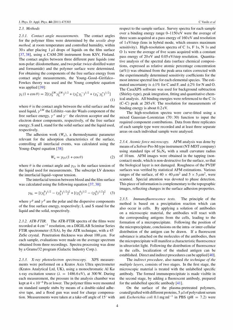
Starting from the literature results [24, 25], the non-piezoelectric PVDF films are treated in a CO2 MW plasmain order to create acidic groups on the surface. Theplasma conditions, such as plasma power, the distancebetween the sample and the surfatron, treatment time andvolume flow rate (Q), are varied for establishing thetreatment parameters which constitute a good compromisebetween optimum functionalization and minimum degradation(figures 2(a)–(f )).
After the plasma treatment, the hydrophilic character ofthe PVDF samples significantly increases under all appliedconditions, a behaviour proved by the decrease in the contactangle with water with respect to the untreated film (figures 2(a)and (b)); this was observed both for the distance between thesample and the surfatron (figure 2(a)), and for the treatmenttime (figure 2(b)), showing minimum values at 0.1 m distanceand 30 s treatment time.
Improvement of this characteristic is necessary forapplications in which adhesion with other macromolecules ormetals is important [44].
After plasma exposure, the acid–base component of thefree surface energy significantly increases when compared
with the pristine sample, for all used discharge parameters.As polymer-surface functionalization under plasma exposureis a very rapid phenomenon that generally occurs within lessthan 1 min [45], the acid–base component of the free surfaceenergy significantly increases during the first 5 s, after which itsvalue remains almost constant for the entire period of plasmaexposure (figure 2(c)). This indicates that the concentration ofpolar groups within the depth of the contact angle measurement(∼0.5 nm) reached the saturation level within 30 s of plasmatreatment time, as also evidenced by other authors [46–48].
For an applied power of 10–50 W, γ abS has a maximum
value of ∼8–12 mN m−1 (figure 2(d)). When compared withthe pristine sample, the increase in the acid–base component ofthe free surface energy under CO2 plasma treatment evidencesthe incorporation of polar functions (oxygenated species),which agrees with the literature data [25, 30]. After plasmatreatment, the atomic concentration of oxygen increaseddramatically and small amounts of incorporated nitrogen werealso observed [49]. Klomp et al showed that titration datarevealed significantly higher surface concentrations of thecarboxylic groups after CO2 glow discharge [50].
The biocompatibility characteristics are also improved byplasma treatment, the interfacial tension with blood and tissuesdrastically decreasing from 27 mN m−1, for the untreatedPVDF, to values tending towards the biocompatibility zone(below 9 mN m−1) (figure 2(e)).
In the meantime, the adhesion work changes from72 mN m−1, for the untreated sample, to a value around100 mN m−1 (figure 2(f )) for all used discharge conditions,evidencing the obtainment of surfaces with improved adhesionproperties. This behaviour could be a sign of a possible betteradherence between the plasma-treated PVDF substrate andother materials.
Using UV spectroscopy (the absorbance of the solutionwas measured at 562 nm by UV–VIS spectroscopy), theamount of adsorbed protein was determined by comparison ofthe absorbance of the samples with a calibration curve. Threerepetitions were performed for all samples. In the meantime,high-precision weighing of the samples was done. It has beenappreciated that, after plasma treatment and subsequent airexposure, a decrease in weight of about 0.6–0.8 µg cm−2 wasobserved in all three cases.
Based on the results of contact angle analysis, and alsoon weight loss determinations for the PVDF samples exposedto MW plasma, using CO2 as a discharge gas at differentdischarge parameters (figure 2), one may conclude that theoptimal conditions which allow improvement of the surfaceproperties of the polymer films (which are close to saturation,with minimum degradation) are as follows:
(I) Plasma CO2: Q = 16×10−8 m3 s−1, P = 50 W, t = 30 s,d = 0.1 m, while for N2 and N2/H2 plasmas, according toprevious results [30], the optimal parameters of dischargeare as follows:
(II) Plasma N2: Q = 16 × 10−8 m3 s−1, P = 50 W, t = 60 s,d = 0.1 m;
(III) Plasma N2/H2 in the ratio 25/75: Q = 16 × 10−8 m3 s−1,P = 50 W, t = 60 s, d = 0.1 m.
5

J. Phys. D: Appl. Phys. 44 (2011) 475303 C Vasile et al
0.00 0.04 0.08 0.12 0.16
60
80
100θ
wat
er (
º)
θ w
ater
(º)
d ((a) (b)
(c) (d)
(e) (f)
m)0 10 20 30 40 50 60
55
60
65
70
75
80
85
90
t (s)
0 10 20 30 40 50 60 70 80
5
10
35
40
45
γ S
ab, γ
S (m
N/m
)
power (W)
γS
ab
γS
0 10 20 30 40 50 600
10
20
30
40
50
60
γS
ab
γS
γ S
ab, γ
S (m
N/m
)
time (s)
0.05 0.10 0.15
9.6
10.0
10.4
10.8
11.2
γ SL (
mN
/m)
d (m)
0 5 10 15 20 25 30
70
75
80
85
90
95
100
105
110
Wa (
mN
/m)
Q (m3/s) * 6*107
Figure 2. Surface properties of the PVDF film, obtained after CO2 plasma exposure for different discharge parameters. Water contact angleversus the distance between the sample and the surfatron (a) (for constant values of Q = 10 sccm, P = 50 W, t = 30 s) and the exposuretime (b) (for constant values of Q = 10 sccm, P = 50 W, d = 10 cm); the acid–base component and the free surface energy versus thedischarge power (c) (for constant values of Q = 10 sccm, d = 10 cm, t = 30 s) and the treatment time (d) (for constant values ofQ = 10 sccm, P = 50 W, d = 10 cm); the interfacial tension between blood and the surface versus the distance between the sample and thesurfatron (e) (for constant values of Q = 10 sccm, P = 50 W, t = 30 s); the adhesion work versus the gas flow (f ) (for constant values ofP = 50 W, t = 30 s, d = 10 cm).
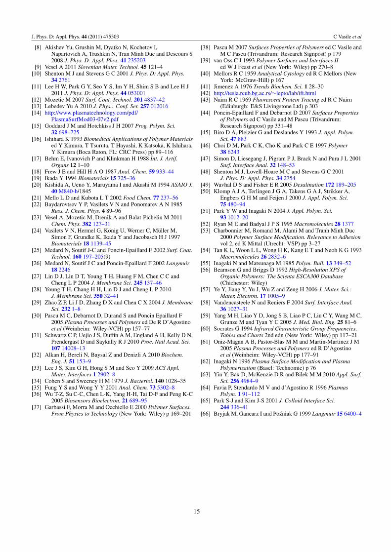
The surface chemical environment and the atomic concentra-tions (%) present on the surface of the pristine PVDF films,plasma-pretreated and modified with proteins, were obtainedusing XPS. The XPS survey spectra of untreated and plasma-treated/modified samples are shown in figure 3, and associateddata are given in table 1.
A comparison between the survey spectra presented infigure 3 reveals that C and F are the predominant species(usually found on virgin PVDF surface) and, as expected,new characteristic O and N emission peaks appeared in
the modified PVDF samples spectra, due to plasma and/orsubsequent treatment. An analysis of the data presented intable 1 shows some increase in the percentage of carbon, adrastic decrease in fluorine percentage, as well as an importantincrease in the percentage of oxygen and nitrogen atoms foreach treated sample, comparatively with the reference sample(PVDF). This situation suggests that the F content at thesample surface was reduced after this treatment, probably asa result of fluorine loss by chain breaking in the polymer,and of the chemical reorganization induced by the electrons
6

J. Phys. D: Appl. Phys. 44 (2011) 475303 C Vasile et al
Figure 3. XPS survey spectra of (a) pristine PVDF film, (b) CO2 plasma treated, (c) CO2 plasma treated and coated with protein A, (d) CO2
plasma treated and grafted with protein A, (e) CO2 plasma treated and coated with triglycine, (f) N2 plasma treated, (g) N2 plasma treatedand coated with protein A, (h) N2 plasma treated and grafted with protein A, (i) N2 plasma treated and coated with triglycine, (j) N2 plasmatreated and grafted with triglycine, (k) N2/H2 plasma treated, (l) N2/H2 plasma treated and coated with protein A, (m) N2/H2 plasma treatedand grafted with protein A, (n) N2/H2 plasma treated and coated with triglycine, (o) N2/H2 plasma treated and grafted with triglycine.
Table 1. Experimental atomic composition (%) and different atomic ratios obtained by XPS analysis for CO2 plasma-activated andprotein-modified PVDF surfaces.
Sample % C % F % O % N O/C O/F N/F N/C
PVDF 53.8 43.2 2.4 0.2 0.045 0.06 0.005 0.003(A) CO2 plasmaPVDF/CO2 plasma 81.3 8.8 7.5 0.4 0.093 0.85 0.05 0.005PVDF/CO2 plasma/coated protein A 62.9 11.7 13.8 5.6 0.219 1.18 0.50 0.089PVDF/CO2 plasma/grafted protein A 63.8 16.3 10.9 5.2 0.171 0.67 0.32 0.081PVDF/CO2 plasma/coated triglycine 68.1 11.1 7.8 1.0 0.163 0.70 0.090 0.015
(B) N2 plasmaPVDF/N2 plasma 66.1 16.6 5.62 2.3 0.085 0.34 0.14 0.03PVDF/N2 plasma/coated protein A 63.7 9.4 16.7 6.2 0.262 1.78 0.66 0.097PVDF/N2 plasma/grafted protein A 70.6 9.5 11.3 4.4 0.160 1.19 0.46 0.06PVDF/N2 plasma/coated triglycine 48.7 7.19 6.04 2.9 0.124 0.84 0.403 0.06PVDF/N2 plasma/grafted triglycine 57.5 7.93 7.88 4.6 0.137 0.994 0.58 0.08
(C) N2/H2 plasmaPVDF/N2/H2 plasma 69.8 21.55 9.05 1.25 0.129 0.42 0.058 0.0179PVDF/N2/H2 plasma/coated protein A 57.6 20.1 14.2 1.7 0.247 0.71 0.084 0.0295PVDF/N2/H2 plasma/grafted protein A 45.2 7.82 8.84 1.9 0.195 1.13 0.243 0.042PVDF/N2/H2 plasma/coated triglycine 67.0 8.7 13.0 2.7 0.194 1.49 0.310 0.040PVDF/N2/H2 plasma/grafted triglycine 56.4 7.2 15.1 3.6 0.267 2.09 0.5 0.064
generated in the plasma. Plasma exposure led to weight lossand changes in the chemical composition on the polymersurface. Selective surface modification of fluoropolymersintroduces various functional groups, without altering the bulkproperties. The results may be summarized as follows: theremote hydrogen plasma ensured the most effective abstractionof fluorine [51]. The loss of surface fluoride was attributedby Ryan and Badyal [52] to vacuum ultraviolet photons, ion-beam treatment or electron impact dissociation. Charbonnieret al used XPS to assess the effects of RF plasma treatments
on PTFE substrates in various gaseous atmospheres [53]. Inall cases, short treatment times (<1 min) were efficient, along time creating a certain surface roughness. N2 plasmaprovokes moderate defluorination, associated with oxygenand nitrogen uptake. N2 originates from plasma treatmentitself and also, very likely, from the post-reaction with theventing gas. The oxygen atoms are both in the form ofalcohol (C–OH) or/and carbonyl (C=O) groups and of epoxyradicals, while the nitrogen atoms appear as amino (C–NH2)
groups.
7

J. Phys. D: Appl. Phys. 44 (2011) 475303 C Vasile et al
Figure 4. Fitted C 1s, N 1s, O 1s and F 1s envelopes for (a) pristine PVDF film, (b) CO2 plasma treated, (c) CO2 plasma treated and coatedwith protein A, (d) CO2 plasma treated and grafted with protein A, (e) CO2 plasma treated and coated with triglycine.
Subsequent exposure of the plasma-treated surface toair causes oxygen incorporation onto the PVDF surface,leading to surface oxidation and formation of peroxide andhydroperoxide species [54]. These new species formed on theCO2 plasma-pretreated PVDF surfaces (after air exposure) canserve as active sites for the subsequent adsorption/grafting ofproteins (see below).
As the surface of all treated samples is enriched inoxygen-containing functionalities, one may safely assess thathydrophilicity of the surface films is improved by CO2 plasmatreatment, in accordance with contact angle measurementresults. The CO2 plasma technology provides superior surfacetreatment, to improve adhesion on a wide variety of materials.The combination of CO2 with plasma discharges significantlyincreases the polar component of the free surface energy.The CO2 plasma produces ablation of the outermost oxidizedlayer of the polymer surface and noticeably increases theadhesive bond strength, because of the different chemical andmorphological surface modifications produced by the plasma.Formation of carboxyl groups is one of the main effects ofPVDF film exposure to the CO2 plasma [24, 55].
Figure 4 provides the high-resolution C 1s, N 1s, O 1sand F 1s XPS spectra for untreated and modified PVDFsamples; also, variation of the corresponding areas—table 2—was considered to evidence differences between samples.
The PVDF C1s spectrum (figure 4(a)) can be curve-fitted with four peak components, from the chemically non-equivalent carbon atoms: two major peaks (noted C1 and C4)at 286.38 eV and 290.97 eV are related to CH2 and CF2 species,respectively, and two smaller peaks (C2 and C3) at 285.07 eV
(attributed to C–C/C–H) and 288.9 eV (characteristic of theC–O bond) [56, 57].
The C2 and C3 peaks detected for the virgin PVDF sample,in addition to the expected peaks for the CH2 and CF2 species,suggest that the PVDF film exhibits low oxidation, possiblyarising during sample storage. When comparing the spectrumof untreated PVDF with the spectra of CO2, N2 and N2/H2,plasma-treated and coated/grafted with protein A or triglycinemodified samples, some important differences appear. Theshape of the C1s peaks changes after treatments, indicatingthat new groups are implanted. Basically, the C 1s core-levelspectra of the modified samples are similar (in broadness, withonly small position shifts) with the spectrum of the referencesample, except for the reorganization of the C2 peak and theratio of peak intensities. At a binding energy around 288.4 eV,the C3 peak could be attributed to a carbon surrounded byfluorine and nitrogen [58]. The most considerable changeswere observed for the CO2 plasma-treated and coated/graftedwith protein A samples. A quick decrease in the percentageof the C4 peak (assigned to the CF2 component; around290.0 eV), accompanied by an increase in the percentage of C2(typical of oxygenated or nitrogen species; between 286.24 and286.44 eV) for each modified PVDF sample, comparativelywith the reference sample, is evident. The XPS C 1s core-level spectra for protein-coated surfaces were deconvoluted in4 or 5 peaks: 284.6 and 285.4 eV (C–C and C–H), 286.3 and286.5 eV (C with amine), 288.1 eV (C with O, carbonyl oramide bond) and 298.3 eV (C with carboxylic acid) [59]. Thesurface coated with proteins displayed a significant increasein the C–N and amide group. Variation of O 1s and N 1swith respect to the C 1s signal ratios was correlated with the
8

J. Phys. D: Appl. Phys. 44 (2011) 475303 C Vasile et al
Table 2. Area (at%) of C 1s peaks for untreated and modified PVDF samples.
Area (at%)
Carbon Nitrogen Oxygen Fluorine
Sample/atom type C1 C2 C3 C4 C5 N1 N2 N3 O1 O2 O3 O4 F1 F2
PVDF 38.3 5.3 16.5 39.9 — — — — 19.2 80.8 — — 57.6 42.4PVDF/CO2 plasma 57.1 25.9 2.9 14.1 — 87.7 12.3 — 88.5 11.5 — — 4.6 95.4PVDF/CO2 plasma/coated protein A 52.7 28.7 8.2 10.3 — 93.1 6.9 — 49.6 46.3 4.1 — 57.6 42.4PVDF/CO2 plasma/grafted protein A 37.0 35.4 9.6 18.0 — 76.8 23.2 — 54.8 41.9 3.3 — 4.6 95.4PVDF/CO2 plasma/coated TG 43.4 33.1 2.8 2.2 18.5 94.1 5.9 — 80.9 10.4 8.7 — 100.0 —PVDF/N2 plasma 42.8 34.4 6.3 7.7 8.8 100.0 — — 46.5 53.5 — — 100.0 —PVDF/N2 plasma/coated protein A 55.2 6.8 — 38.0 67.0 33.0 — 80.4 19.6 — — 100.0 —PVDF/N2 plasma/grafted protein A 57.9 28.2 4.0 2.5 7.4 85.3 2.4 12.3 93.0 7.0 — — 100.0 —PVDF/N2 plasma/coated TG 35.1 30.6 16.0 18.4 — 94.7 5.3 — 81.5 18.5 — — 100.0 —PVDF/N2 plasma grafted triglycine 72.2 22.2 0.9 3.1 1.6 89.6 3.3 7.1 22.3 59.6 11.1 7.0 17.4 82.6PVDF/N2/H2 plasma 33.5 37.1 13.6 15.8 — 100.0 — — 75.1 24.9 — — 100.0 —PVDF/N2/H2 plasma/coated protein A 50.0 32.2 9.9 7.9 — 100 — — 54.7 43.9 1.4 —PVDF/N2/H2 plasma/grafted protein A 62.3 28.8 4.9 2.8 1.2 100.0 — — 92.0 8.0 — — 4.4 95.6PVDF/N2/H2 plasma/coated TG 60.1 24.9 4.4 9.9 0.7 100.0 — — 93.7 6.3 — — 100.0 —PVDF/N2/H2 plasma/grafted TG 46.8 35.1 11.4 5.4 1.3 100 — — 75.2 17.4 7.4 — 6.9 93.1
significant presence of chemical species on the coated/graftedsurfaces. For the untreated sample surface, the O 1s core-levelspectrum displays a broad peak that can be curve-fitted withtwo peak components, with binding energies at 532.27 andat 533.73 eV—figure 4. After CO2 plasma treatment, thesesignals are shifted to slightly higher binding energies. Fromthe obtained XPS results, some qualitative comparisons canbe drawn: (a) change in the shape of the O 1s photoelectronpeak and a relative intensity of curve-fitted peak componentsduring CO2 plasma treatment and coating/grafting proteinprocess; (b) emerging of the O3 component in the spectrashown in figures 4(c), (d) and (e) (O 1s spectra) is a reasonableconsequence of the grafting or coating process.
In the case of an untreated film (figure 4, N 1s spectrum),no N component was detected on the sample surface, which isconsistent with the absence of nitrogen in the PVDF structure.For all CO2 plasma-treated samples, an asymmetric signal,with a main peak (N1, at 400.0 eV), attributed to the amino tailgroups, and a second one (N2, at 401 or 402 eV), due to thepositively charged amine, were detected. Peak N1 represents76.8–94.1% (table 2) of the whole N 1s signal and suggeststhat the free NH2 groups are the major form of nitrogen onthe modified surface. The presence of this signal reinforcesthe validity of the C 1s signal deconvolution, where a C3component appears after proteins’ coating or grafting process.
High-resolution scans of the XPS spectra of F 1s levels forthe untreated PVDF film show two peaks at 686.85 eV (57.6%),assigned to the F–C–F groups (F1), and at 688.48 eV (42.4%),due to the C–F groups (F2). The presence of these signalsindicates the existence of more than one fluorine compound onthe surface of the untreated polymer and suggests a significantconversion (57.6%) of the F–C–F to C–F groups. Afterplasma treatment, F2 is dramatically reduced. This behaviour,as well as the fluorine concentration, still significant in themodified samples (table 1), reinforces the idea that the loss offluorine during all kinds of plasma and grafting treatments isaccompanied by a drastic decrease in the F–C–F groups, whichis compensated by an increase in the C–F groups.
XPS spectra show that the treatment in CO2 plasma leadsnot only to the oxidation of PVDF (7.5%), but also to theformation of CF and terminal CF3 groups. Taking into accountthat the decrease in the F/C ratio (from 0.80 to 0.108) exceedsthe increase in the O/C ratio (from 0.045 to 0.094), one canconclude that the CO2 plasma treatment leads to the effectiveformation of double bonds and weak cross-linkings. Asillustrated in table 2, the peak area of F1 decreased more than12 times after CO2 plasma activation.
The XPS results agree with ATR-FTIR spectra (notshown). The CO2 plasma treatment led to new absorptionpeaks with maxima at 1881 cm−1 and 1725 cm−1, whichcan be attributed to COF carboxylic acid fluoride and to–CF=CF– double bonds, respectively. Characteristic bandswere observed at 3200 cm−1 (OH str.), 1710 cm−1 (C=O str.)and 800 cm−1 (COOH out-of-plane def.) in the ATR-FTIRspectrum [60].
The AFM image—figure 5—of the PVDF-treated CO2
plasma (b) proves surface modification. Also, surfaceroughness increased from 0.084 to 0.135 µm.
It can be concluded that the acidic surface was createdby the CO2 plasma treatment, surface roughness beingincreased. Plasma treatments produce pits on the surface,ablation of the oxidized surface layer and functionalizationby implantation of oxygen functionalities, mainly carboxylgroups [25, 55, 61, 62].
3.2. Protein covering of the surfaces
Two techniques can be used to simplify the process with strongadhesion of the activated layer to substrates for covalentlybinding the proteins: plasma modification of polymers (if thesubstrates are polymers) and plasma deposition of polymer-like materials onto any solid surface, by adding polymerprecursors into the plasma [63]. If proteins are immobilized onsurfaces with non-specific and uncontrolled weak interactions,they are susceptible to detach quickly with time, within a fewhours or days, which may result in a loose contact between
9

J. Phys. D: Appl. Phys. 44 (2011) 475303 C Vasile et al
Figure 5. AFM images of the samples: PVDF untreated (a) and pretreated with CO2 plasma (b).
implants and the biological tissues, or in an uncontrollabledecrease in biosensors’ sensitivity.
Comparing our present data with that previously obtained[25, 30] and also with literature results, we can conclude thatthe above-mentioned three kinds of active surfaces obtainedunder optimal conditions of plasma treatment, underwentcovering with proteins, namely acidic surfaces (obtained byCO2 plasma activation) [61], basic surfaces (obtained by N2/H2
plasma activation [64]) and amphoteric surfaces (obtained byN2 plasma activation [65, 66]), in all cases after exposure toair for the same period of time of about 1 min.
Protein coating was achieved by both physisorption andgrafting, according to the procedures described above.
Covering/grafting with proteins leads to an increased filmweight, up to an average of 4.8–5.6 µg cm−2 for adsorbed TG;2.8–3.1 µg cm−2 in the case of grafted TG; 2.5–3.2 µg cm−2
for adsorbed protein A and 1.3–2.8 µg cm−2 for graftedprotein A.
Comparing the samples treated in different plasmas, itappears that, in all cases, the contact angle with waterdecreases with respect to the untreated PVDF—figure 6. Itis obvious that, in all cases, the PVDF surface becomesmore hydrophilic. The larger decrease observed for N2/H2
plasma—figure 6(a)—could be explained by the differentkinds of implanted functional groups and also by their possibleincreased number. Favia et al found that N2 or NH3 plasmatreatments give rise to N-containing functionalities [64], suchas amine (–NH2), imine (–CH=NH), nitrile (–C≡N) onpolymer surfaces, as well as to oxygen-containing groups,such as amide (–CONH2), due to post-discharge atmosphericoxidation. The phenomenon is consistent with the factthat the water contact angle measurement is an even moresurface-sensitive technique than XPS. Water contact anglemeasurements have a surface sensitivity of 1 nm or less incomparison with a probing depth of about 7.5 nm for the C 1sphotoelectrons, at a take-off angle of 75◦ in an organic matrix.Generally, covering with proteins does not significantly changethe surface wettability of the PVDF films treated in N2/H2
plasma, except for the case when the sample is grafted withTG; for this one, the contact angle with water has a highervalue, evidencing that this surface becomes more hydrophobicthan the other ones.
The XPS survey spectra of the plasma-treated and protein-covered samples (figure 3) also present some major differencescompared with that of the untreated PVDF film as follows.
untreated N2 N2/H2 CO20
20
40
60
80
θ wat
er(º
)
(a)
(b)
untreated
N2/H2
N2/H2+prA adsorbed
N2/H2+prA graft
N2/H2+TG adsorbed
N2/H2+TG graft
0 20 40 60 80
θwater
(º)
Figure 6. Contact angle of water on the PVDF surface plasmatreated with different gases (a) and after coating/grafting withproteins (b).
(a) The O 1s and N 1s peaks, centred at about 534 eV and400 eV, respectively, are well-defined and prominent only inthe XPS survey spectra of the modified samples, because ofthe presence of the oxygen- and nitrogen-containing specieson the PVDF surface, meaning that an interaction between theproteins used and the polymer surface may have taken place.(b) The C 1s characteristic peaks and their correspondingcontent (%) (table 2) are higher for all modified samples thanfor the untreated one. The highest value for carbon content (%)was registered for the PVDF/N2/H2 plasma/grafted protein Asample. (c) After each modification step, the F/C atomic ratiosubsequently decreased, while the O/C atomic ratio increased.(d) The appearance of N 1s peak is accompanied by a decreasein the F/C atomic ratio (not shown) and an increase in theO/C ratio, after protein covering or grafting, as indicated
10

J. Phys. D: Appl. Phys. 44 (2011) 475303 C Vasile et al
by the presence of amino groups on the modified PVDFsurface (table 1). (e) Analysis of atomic composition (table 1)revealed a very low concentration of fluorine and a significantconcentration for oxygen and nitrogen, indicating a very goodanchoring of protein A onto the PVDF surface.
A significant increase in N content may be observed afterdeposition/grafting of proteins, the highest one being observedwhen using protein A—table 1. This observation is consistentwith the highest value (N/F = 0.5) obtained in the case ofthe CO2 plasma-treated sample coated with protein A. Thedrastic defluorination of the modified PVDF samples and theemergence of new O and N peaks, characteristic of multiplenitrogen or oxygen functions, testify to the presence of proteinson the modified samples’ surface. As the surface of all treatedsamples is enriched in nitrogen- or in oxygen-containingfunctions, it may be safely assessed that the hydrophilicityof films’ surface is improved by plasma treatment.
As expected for plasma treatments, new peaks (noted asC2, C3, C5) emerged in each C 1s spectrum (figure 4) between285.86 and 290.06 eV (for all treated samples, except the N2
plasma-treated and coated with protein A polymer sample), asa consequence of PVDF surface oxidation.
The appearance of C2, C3 or C5 peaks indicatesthe formation of oxygen–carbon (O–C–O, C=O, O=C–O)and nitrogen–carbon bonds (N–C=O, C–NH2) between thepolymer and proteins—table 2.
These new characteristic signals are typical of the C–N,C–N–F, O–C–O and O=C–O components. A large increasein C1 concentration, from about 38.3% (untreated PVDF)to 57.9% (the N2 plasma-treated and grafted with protein APVDF sample), and to 72.2% (N2 plasma-treated and graftedwith triglycine) (table 2) is observed, this enrichment beingattributed to the two grafted proteins, which contain aliphaticmoieties. The XPS data of table 2 show that the content ofC1 is slightly increased (42.8%) in the case of the N2 plasma-treated PVDF sample, and it is only insignificantly (35.1%)or dramatically (6.8%) decreasing for PVDF treated with N2
plasma and coated with triglycine and protein A. It can be seenthat the variation of the C1, C2, C3 and C5 (when present)low binding energy is simultaneously compensated by thesignificantly reduced intensity of the high-binding-energy C4component, attributable to the CF2 groups. As indicated inthe literature, even a mild plasma pretreatment of fluorine-based polymers induces a substantial damage of the polymersurface, as a result of defluorination [22]. Consequently,chain mobility and surface permeability of the PVDF polymerare significantly increased, thus possibly or substantiallyfacilitating grafting of the polar segments from proteins.
For all treated samples, in addition to the N1 and N2main peaks, two other peaks, which can be assigned to thenitrogen involved in oxidized environments (probably betweenthe terminal amino group and oxygen group near the surface),are found.
Peak N1 represents 76.8–94.1% of the whole N 1s signaland suggests that free NH2 groups are the major form ofnitrogen on the modified surface—table 2. The presence ofthis signal reinforces the validity of signal N 1s deconvolution,where a N3 component appears after proteins’ coating orgrafting.
A large increase in the nitrogen percentage and asignificant increase in the oxygen content are registered forall protein-modified surfaces, reflecting that the two proteinsare anchored to the PVDF surface. A comparative analysisshows that protein A is grafted or coated more efficiently thantriglycine on the acidic (CO2 plasma-treated) and basic (N2/H2
plasma-treated) PVDF surface.Peak N 1s is very prominent in the XPS high-resolution
spectra of the N2/H2-modified samples (while the controlPVDF sample spectrum does not show such a characteristicpeak). A single strong symmetrical N 1s peak, centred atabout 400 eV for the N2/H2 plasma-treated sample and at397.33–397.48 eV for the protein-coated or grafted samples,suggests that the nitrogen-containing groups (neutral aminotail) are successfully anchored on the PVDF chain via directgrafting or protein monolayer deposition. As shown in table 2,grafting of triglycine (3.6% N) is more successful than that ofprotein A (1.9%).
In oxygen core-level spectra, an additional very broadminor component peak at about 3.5 eV in binding energy isdetected in the O core-level spectrum of the plasma-treatedsamples and of the coated or grafted protein surfaces (notshown), which is a reasonable consequence of the graftingor coating process. Change in the shape of the O 1sphotoelectron peak and the relative intensity of the curve-fittedpeak components occurred after plasma treatment and aftercoating or grafting with protein.
The occurrence of the O3 component in the spectra isa reasonable consequence of the grafting or coating process.The signal is asymmetrical and has two peaks (except forthe N2 plasma-treated and grafted with triglycine PVDFsample that presents four signals) from chemically inequivalentoxygen atoms. By deconvolution of the two peaks at about532.5 eV and 534.5 eV, respectively (table 2), the intensityincreases at 532.5 eV and decreases at 534.5 eV, indicatingthat surface chemistry changes after the plasma treatment andcoating/grafting with proteins. It is well known that the plasmatreatment is a complex process and its exact mechanism isnot precisely established. However, it is generally agreedtoday that a plasma treatment induces surface oxidation andconsequently enhances the content of polar species responsiblefor the increase in hydrophilicity.
Two types of oxygen species are evidenced for theuntreated PVDF film, the N2/H2 plasma-treated sample, theN2/H2 plasma-treated and grafted with protein A sample, whilethe N2/H2 plasma-treated and coated with triglycine samplesexhibit three kinds of oxygen atoms: O–C=O, C–O, O–C–O.These results are very satisfactory and are in good agreementwith reported data for similar systems.
After plasma treatment and protein coating or grafting, F2is reduced dramatically (in the case of protein A) or completely(for the TG protein). This behaviour and also the fluorineconcentration, still significant in the modified samples (tables 1and 2), reinforce the idea that loss of fluorine takes place duringplasma and grafting treatments and that, in some cases, coatingwith proteins is not uniform. The loss of fluorine is related tothe plasma treatment, this effect being more pronounced forthe PVDF samples activated with the CO2 and N2/H2 plasmas,
11

J. Phys. D: Appl. Phys. 44 (2011) 475303 C Vasile et al
Figure 7. 3D AFM images of the PVDF surfaces after plasma activation and deposition of protein A and TG (40.2 × 40.2 µm2).
comparatively with the effect observed for the PVDF sampletreated with the N2 plasma.
The change in the shape of the F 1s high-resolution spectraduring plasma treatment and grafting/coating with proteinsclearly shows the characteristics of the fluorine-rich speciesof the untreated PVDF sample surface, with a lower peak at686.85 eV (57.6% of the whole N 1s signal) and a higherpeak at 688.48 eV (42.4% of the whole N 1s signal). It isobvious that the F 1s peak is slightly shifted to a higher bindingenergy position after plasma treatment and coating/grafting,this positive shift indicating the decrease in electron densityaround the F atoms, and that the chemical state of fluorinechanges after applied modifications.
On the basis of the analysed XPS data, the followingcan be concluded. (a) The carbon content decreases withrespect to that of the reference in all cases, probably becausesurface composition is determined mainly by proteins. (b)There are no major differences between the surfaces coveredby adsorption of proteins and the grafted ones; probably, thedifference mainly refers to the stability of the deposited layer.When using TG, the nitrogen content is higher for the casein which the protein is grafted. (c) The oxygen content isalso increased with respect to the reference in all cases andespecially after covering with proteins, and the variation seemsto be similar to that found in the nitrogen content. After plasmatreatment, all surfaces became more hydrophilic, owing tothe grafting of polar nitrogen or oxygen-containing functions.(d) N2 plasma led to the grafting of a wide variety of polarspecies, leading to an amphoteric surface. (e) In the caseof proteins’ adsorption/grafting, both the acidic and/or thebasic groups of proteins will interact with the complementarybasic or acidic active sites, created on the surfaces by N2
and N2/H2 or CO2 plasma treatment, respectively. (f) Theoxygen and nitrogen contents increase considerably after
plasma treatment and coating/grafting with proteins of thePVDF reference sample, the highest values being registeredfor the N2/H2 plasma-treated sample and for PVDF N2/H2
plasma-pretreated/grafted with triglycine. This result suggeststhat, in this case, triglycine was more successfully graftedonto the PVDF surface than protein A, while in the other twocases of CO2 and N2 plasma activation, protein A was bettergrafted. (g) In every case, a strong surface defluorination wasobserved. The significantly reduced intensity of the F 1s signaland the related data presented in table 2 for all treated samplesrevealed a massive defluorination of the surface, in all cases, asa result of the electron attack generated by plasma action andsurface coating with proteins. Considering that the fluorinepeak was not totally suppressed after plasma treatment, a non-homogeneous grafting or coating of the PVDF surface withproteins occurred. (h) The most obvious change in all C 1sspectra of the modified samples is observed in the number andtype of carbon atoms. The untreated PVDF exhibits two typesof characteristic carbon atoms, while the treated samples haveat least four signals—table 2. As expected for plasma-treatedsurfaces, some oxidized components of C 1s appear in the285.85–293.30 eV range (e.g. C2, C3 and C5), in addition tothe two main peak components assigned to the PVDF chains(e.g. C1 and C4). (i) Covalent grafting or physical depositionof a protein layer results in the introduction of amino groupson the PVDF surface. The signal at about 288.5 eV, attributedto N–C=O groups, overlaps the O–C=O signals, whereas thepeak at 286.3 eV is characteristic exclusively of the C–NH2
groups. This last mentioned peak is therefore a proof ofprotein’s presence on the PVDF surface. (j) The intensity andcontent of the C4 peak is further decreased comparatively withthat of the non-treated PVDF film, which suggests that theplasma treatment induces a loss of fluorine at the surface. Thisdefluorination is accompanied by an enhancement of the newlyformed multiple nitrogen or oxygen functions.
12

J. Phys. D: Appl. Phys. 44 (2011) 475303 C Vasile et al
Figure 8. Phase images for PVDF after plasma activation and grafting with protein A or TG.
Table 3. Average roughness of the MW plasma-treated surfaces,and covered and grafted with proteins A and TG.
Roughness, nm forSample 10 × 10 µm2
Reference 84CO2 135CO2+PrA adsorbed 153CO2+TG adsorbed 172CO2+ PrA graft 143CO2+ TG graft 185N2 215N2+PrA adsorbed 125N2+TG adsorbed 147N2 + PrA graft 49.3N2+ TG graft 61.6N2/H2 150N2/H2+PrA adsorbed 60.4N2/H2+TG adsorbed 165N2/H2+ PrA graft 130N2/H2+ TG graft 118
The presence of a new surface layer was confirmed byAFM images of the surface. Coating with proteins leads tonew surface characteristics—figures 7 and 8.
The AFM images (figure 7) show rough surfaces, whateverthe nature of the treatment, while the phase images (figure 8)induce the idea of more smooth surfaces, especially with N2 orN2/H2 plasma activation and adsorption/grafting of proteins.
Although the absolute roughness cannot be estimated, theroot mean square roughness of the surface was determinedsystematically, both before and after treatments (table 3).Plasma activation induces a roughness from 83 nm to the
-0.4 -0.2 0.0 0.2 0.4
0
1
2
3
4
5
6
7
8
9
10
ρ (
mm
-1)
z (µm)
reference N2/H2 N2/H2 + PrA adsorbed N2/H2 + TG adsorbed N2/H2 + PrA grafted N2/H2+ TG grafted
Figure 9. Histograms of the samples treated in different plasmasand covered/grafted with proteins.
highest value in the case of N2 plasma treatment (215 nm).Protein deposition and grafting onto CO2 plasma-treatedsurfaces lead to a relatively higher roughness than that ofthe plasma-treated surface (a few tens of nm more). Whileroughness of the protein–acidic surface is slightly increasing,that of the protein grafted or adsorbed on the amphotericsurface is decreasing (table 3). Almost all surfaces aresmoother, as already shown by phase images. These resultsshould lead to the conclusion of a high protein depositionor grafting with amino surfaces. On the AFM histogramcorresponding to an area of 40 × 40 µm2, a Gaussian
13

J. Phys. D: Appl. Phys. 44 (2011) 475303 C Vasile et al
Figure 10. Immunofluorescence test results for virgin PVDF (a), N2/H2 plasma-treated PVDF with adsorbed TG (b), grafted with protein A(c) and grafted with TG (d).
distribution by height was observed in all cases—figure 9—which becomes narrower after plasma activation and larger bycoating with proteins, the height of the curves being decreasedfor the samples grafted with proteins with respect to thereference samples and to the surface coated with adsorbedproteins. This should mean that, by these treatments, surfaceswith different characteristics are obtained.
The immunofluorescence test incontestably provedthe successful preparation of the PVDF surfaces formicroorganism detection.
For the virgin or plasma-treated PVDF surface, nofluorescence zones were observed—figure 10(a). Whentreated in N2/H2 plasma and coated with adsorbed proteins,some fluorescence regions are observed (figures 10(b) and(c)), especially with adsorbed TG. Grafting of proteins induceslarger fluorescence regions; the largest fluorescence zones areobserved for the PVDF activated by the N2/H2 plasma andgrafted with TG, which demonstrates the best coupling of thefluorescent antibody tracer with the TG protein grafted on thePVDF surface—figure 10(d). Similar results are obtained forthe surfaces activated by either CO2 or N2 plasma but, in thesecases, the larger fluorescence zones appear when using proteinA in surface treatment, because, in these situations, coveringof the surface with this protein was the most efficient—see theXPS results.
The results agree well with those obtained by XPS; thehigher the amount or the stronger the binding of proteins, thelarger the immunofluorescence zones observed.
4. Conclusions
CO2 plasma treatment of PVDF leads to physico-chemicalsurface modifications, mainly by implantation of acidic groupsonto the surface, due to the interactions between the polymersurface and the reactive species present in the plasma phase(including CO2 species in different energy states, metastable,ions, atoms and radicals), which induces a functionalizationcharacterized by the presence of oxygenated groups on thesurface.
Two new methods are developed for polymer-surfacefunctionalization by subsequent immobilization of protein Aand triglycine through coating/grafting on a PVDF surface,followed by microwave plasma treatment with various gases,such as CO2, N2 and N2/H2.
Using XPS spectroscopy and ATR-FTIR, the formation ofCOF, COOH and O=C– groups after CO2 plasma treatment,and amide and amine after other kinds of plasma activationand protein coating/grafting was detected and characterized.Water contact angle measurements show a gradual decreasein contact angles after proteins’ coating/grafting, indicating anincreased hydrophilicity in these two steps of modification,as also proved by AFM. It has been established that TG wasbetter attached on a surface activated with N2/H2 plasma, whileprotein A on CO2, N2 plasma-activated surfaces.
The proteins immobilized on the PVDF surface exhibitedthe expected activity in coupling of the fluorescent antibodytracer, as assessed by an immunofluorescence test.
The purpose of these coatings is to create biosensors forantibody immobilization and detection. Plasma treatment ofPVDF in a microwave plasma, followed by coating/graftingwith different proteins, proved to be very useful for theappropriate modification of its surface properties, thus leadingto a possible increase in the biocompatibility characteristics ofthe polymer.
The procedure proposed in this paper is likely to have goodpotential in finding new biosensors (finally, the piezoelectricones) that may play an important clinical role.
Acknowledgments
Financial support from CNCSIS (project ID 2541) and COSTaction FA0904 of the European Commission is gratefullyacknowledged.
References
[1] Rossi F and Colpo P 2011 J. Phys. D: Appl. Phys. 44 174017[2] Morent R, De Geyter N and Leys C 2008 Nucl. Instrum.
Methods Phys. Res. B 266 3081–5[3] Mittal K L and Pizzi A 1999 Adhesion Promotion Techniques.
Technological Applications (New York: Marcel Dekker)[4] Liu C Z, Cui N Y, Brown N M D and Meenan B J 2004 Surf.
Coat. Technol. 185 311[5] Guruvenket S, Rao G M, Komath M and Raichur A M 2004
Appl. Surf. Sci. 236 278[6] Bhowmik S, Jana P, Chaki T K and Ray S 2004 Surf. Coat.
Technol. 185 81[7] Coen M C, Lehmann R, Groening P and Schlapbach L 2003
Appl. Surf. Sci. 9729 1–11
14
J. Phys. D: Appl. Phys. 44 (2011) 475303 C Vasile et al
[8] Akishev Yu, Grushin M, Dyatko N, Kochetov I,Napartovich A, Trushkin N, Tran Minh Duc and Descours S2008 J. Phys. D: Appl. Phys. 41 235203
[9] Vesel A 2011 Slovenian Mater. Technol. 45 121–4[10] Shenton M J and Stevens G C 2001 J. Phys. D: Appl. Phys.
34 2761[11] Lee H W, Park G Y, Seo Y S, Im Y H, Shim S B and Lee H J
2011 J. Phys. D: Appl. Phys. 44 053001[12] Mozetic M 2007 Surf. Coat. Technol. 201 4837–42[13] Lebedev Yu A 2010 J. Phys.: Conf. Ser. 257 012016[14] http://www.plasmatechnology.com/pdf/
PlasmaSurfMod03-07v2.pdf[15] Goddard J M and Hotchkiss J H 2007 Prog. Polym. Sci.
32 698–725[16] Ishihara K 1993 Biomedical Applications of Polymer Materials
ed Y Kimura, T Tsuruta, T Hayashi, K Katsoka, K Ishihara,Y Kimura (Boca Raton, FL: CRC Press) pp 89–116
[17] Behm E, Ivanovich P and Klinkman H 1988 Int. J. Artif.Organs 12 1–10
[18] Frew J E and Hill H A O 1987 Anal. Chem. 59 933–44[19] Ikada Y 1994 Biomaterials 15 725–36[20] Kishida A, Ueno Y, Maruyama I and Akashi M 1994 ASAIO J.
40 M840-b/1845[21] Mello L D and Kubota L T 2002 Food Chem. 77 237–56[22] Baydarovtsev Y P, Vasilets V N and Ponomarev A N 1985
Russ. J. Chem. Phys. 4 89–96[23] Vesel A, Mozetic M, Drenik A and Balat-Pichelin M 2011
Chem. Phys. 382 127–31[24] Vasilets V N, Hermel G, Konig U, Werner C, Muller M,
Simon F, Grundke K, Ikada Y and Jacobasch H J 1997Biomaterials 18 1139–45
[25] Medard N, Soutif J-C and Poncin-Epaillard F 2002 Surf. Coat.Technol. 160 197–205(9)
[26] Medard N, Soutif J C and Poncin-Epaillard F 2002 Langmuir18 2246
[27] Lin D J, Lin D T, Young T H, Huang F M, Chen C C andCheng L P 2004 J. Membrane Sci. 245 137–46
[28] Young T H, Chang H H, Lin D J and Cheng L P 2010J. Membrane Sci. 350 32–41
[29] Zhao Z P, Li J D, Zhang D X and Chen C X 2004 J. MembraneSci. 232 1–8
[30] Pascu M C, Debarnot D, Durand S and Poncin Epaillard F2005 Plasma Processes and Polymers ed De R D’Agostinoet al (Weinheim: Wiley-VCH) pp 157–77
[31] Schwartz C P, Uejio J S, Duffin A M, England A H, Kelly D N,Prendergast D and Saykally R J 2010 Proc. Natl Acad. Sci.107 14008–13
[32] Alkan H, Bereli N, Baysal Z and Denizli A 2010 Biochem.Eng. J. 51 153–9
[33] Lee J S, Kim G H, Hong S M and Seo Y 2009 ACS Appl.Mater. Interfaces 1 2902–8
[34] Cohen S and Sweeney H M 1979 J. Bacteriol. 140 1028–35[35] Fung Y S and Wong Y Y 2001 Anal. Chem. 73 5302–8[36] Wu T-Z, Su C-C, Chen L-K, Yang H-H, Tai D-F and Peng K-C
2005 Biosensors Bioelectron. 21 689–95[37] Garbassi F, Morra M and Occhiello E 2000 Polymer Surfaces.
From Physics to Technology (New York: Wiley) p 169–201
[38] Pascu M 2007 Surfaces Properties of Polymers ed C Vasile andM C Pascu (Trivandrum: Research Signpost) p 179
[39] van Oss C J 1993 Polymer Surfaces and Interfaces IIed W J Feast et al (New York: Wiley) pp 270–8
[40] Mellors R C 1959 Analytical Cytology ed R C Mellors (NewYork: McGraw-Hill) p 167
[41] Jimenez A 1976 Trends Biochem. Sci. 1 28–30[42] http://tesla.rcub.bg.ac.rs/∼lepto/lab/ift.html[43] Nairn R C 1969 Fluorescent Protein Tracing ed R C Nairn
(Edinburgh: E&S Livingstone Ltd) p 303[44] Poncin-Epaillard F and Debarnot D 2007 Surfaces Properties
of Polymers ed C Vasile and M Pascu (Trivandrum:Research Signpost) pp 331–48
[45] Biro D A, Pleizier G and Deslandes Y 1993 J. Appl. Polym.Sci. 47 883
[46] Choi D M, Park C K, Cho K and Park C E 1997 Polymer38 6243
[47] Simon D, Liesegang J, Pigram P J, Brack N and Pura J L 2001Surf. Interface Anal. 32 148–53
[48] Shenton M J, Lovell-Hoare M C and Stevens G C 2001J. Phys. D: Appl. Phys. 34 2754
[49] Wavhal D S and Fisher E R 2005 Desalination 172 189–205[50] Klomp A J A, Terlingen J G A, Takens G A J, Strikker A,
Engbers G H M and Feijen J 2000 J. Appl. Polym. Sci.75 480–94
[51] Park Y W and Inagaki N 2004 J. Appl. Polym. Sci.93 1012–20
[52] Ryan M E and Badyal J P S 1995 Macromolecules 28 1377[53] Charbonnier M, Romand M, Alami M and Tranh Minh Duc
2000 Polymer Surface Modification. Relevance to Adhesionvol 2, ed K Mittal (Utrecht: VSP) pp 3–27
[54] Tan K L, Woon L L, Wong H K, Kang E T and Neoh K G 1993Macromolecules 26 2832–6
[55] Inagaki N and Matsunaga M 1985 Polym. Bull. 13 349–52[56] Beamson G and Briggs D 1992 High-Resolution XPS of
Organic Polymers: The Scienta ESCA300 Database(Chichester: Wiley)
[57] Ye Y, Jiang Y, Yu J, Wu Z and Zeng H 2006 J. Mater. Sci.:Mater. Electron. 17 1005–9
[58] Vandencasteele N and Reniers F 2004 Surf. Interface Anal.36 1027–31
[59] Yang M H, Liao Y D, Jong S B, Liao P C, Liu C Y, Wang M C,Grunze M and Tyan Y C 2005 J. Med. Biol. Eng. 25 81–6
[60] Socrates G 1994 Infrared Characteristic Group Frequencies,Tables and Charts 2nd edn (New York: Wiley) pp 117–21
[61] Oniz-Magan A B, Pastor-Blas M M and Martin-Martinez J M2005 Plasma Processes and Polymers ed R D’Agostinoet al (Weinheim: Wiley-VCH) pp 177–91
[62] Inagaki N 1996 Plasma Surface Modification and PlasmaPolymerization (Basel: Technomic) p 76
[63] Yin Y, Bax D, McKenzie D R and Bilek M M 2010 Appl. Surf.Sci. 256 4984–9
[64] Favia P, Stendardo M V and d’Agostino R 1996 PlasmasPolym. 1 91–112
[65] Park S-J and Kim J-S 2001 J. Colloid Interface Sci.244 336–41
[66] Bryjak M, Gancarz I and Pozniak G 1999 Langmuir 15 6400–4
15