Embed Size (px)
Citation preview

Heading prediction in unmanned ground vehicles by laser compass.
Mey Khalili, Richard Weatherly, Robert Bolling, Keven Ring, Bob Grabowski, Kevin Forbes, Cindy CicaleseMITRE corporation7515 Colshire Drive
McLean, VA 22102-7539Email: {mkhalili, weather, rbolling, keven, rgrabowski, forbes, cicalese} @mitre.org
Abstract— This paper presents an on-line algorithm whichprovides high signal to noise ratio heading predictions for un-manned ground vehicles. The algorithm uses cross correlationof SICK laser scans to improve the heading predictions fromGPS. It is tested on our ground vehicles in outdoor urbanenvironment and verified to provide accurate smooth headingpredictions which help with the accurate localization of thevehicle.
I. I NTRODUCTION
Unmanned ground vehicles (UGVs) determine their posi-tion by three parameters: altitude, longitude and heading (i.e.yaw, referred here asη). Heading is the clockwise deviationfrom true North on the X-Y plane The accurate knowledgeof heading is essential for autonomous localization of robotsin an unknown environment. UGVs can obtain the headingfrom a variety of sources such as a magnetic compass,Global Positioning System (GPS) or Inertial MeasurementUnit (IMU). A magnetic compass is sensitive to iron contentin the environment and requires suspension which causesinaccuracy. IMU provides an estimate of the heading throughdouble integration of sensed acceleration and suffers fromintegration drift caused by skidding and measurement er-rors. Usually GPS is the most accurate vehicle localizationmethod. However, it can produce spikes (on the order of 10sof degrees) and requires line of sight to the satellite whichrules out many indoor environments. It also produces noreliable heading at low speeds. Our vehicles operate mostlyat speeds which produce low signal to noise heading fromGPS due to their large size and safety issues. There hasbeen extensive work using cameras as a vision compass todetect the rotational motion of a robot.1]–[3 However, thesealgorithms usually require camera calibration parameters andin general are not suitable for real-time implementation. Theobjective of this paper is to design a fast and inexpensive on-line algorithm to obtain the vehicle heading from the cross-correlation of SICK LMS sweeps when GPS is unreliable.
The outline of the paper is as follows. The subsequent sec-tion introduces MITRE UGVs. Section III presents the algo-rithm’s derivation and parameterization. section IV presentsthe tests of the algorithm and syncing it with GPS, sectionV concludes the paper.
II. ROBOTS
The MITRE Corporation has a number of UGVs. Probablythe best known is a 2004 Ford Explorer Sport Trac, named
Meteor.4], [5 Meteor was designed to participate in the De-fense Advanced Research Projects Agency (DARPA) GrandChallenge, the purpose of which was to design autonomousvehicles capable of completing a 132-mile, off-road course.Meteor was among 23 vehicles that qualified to compete inthe final race.
FIG. 1: Centaur with its sensors.
MITRE also has a pair of Ontario Drive and Gear (ODG)DM950 Centaur Turbo diesel off-road utility vehicles (Fig-ure 1). Since they are skid-steer, they are better suited asmodels of vehicles used in combat. Currently, the Centaurshave one GPS each and two SICK LMS, one scanninghorizontally, and the other vertically. If GPS is unavailableor noisy, the vehicles have no other means of predictingheading. The Laser Compass algorithm was designed tomitigate this problem. The specifications of the horizontalSICK LMS are provided in Table I.
TABLE I: Relevant specifications of horizontal SICK LMS. Trans-lation and rotation are with respect to vehicle’s origin.
Translation (m) Pitch, yaw, Roll (◦) Range (m) FOV (◦) f (Hz)
1.6, 0.0, -0.8 0.0, 0.0, 0.0 80 180 20
All three UGVs have the same operating system archi-tecture called wombat. The details of the design and imple-mentation of wombat are presented elsewhere.6]–[8 Wombatis a distributed system comprising the robots and the robotcommand center. The software architectures consist of agentswhich receive state information, change it, and pass it toother parts of the system. Messages from different sensors
© The MITRE Corporation. All rights reserved

and components regardless of the programming language,are broadcast via the UDP protocol on a given subnet.This scheme facilitates the use of multiple programminglanguages. Safety-critical and real-time parts of the systemare written in the Ada. Navigation, maneuvering, user inter-action, and visualization software are written in Java. Thesystem runs on GNU/Linux and Windows.
III. M ETHODS
A. Cross-Correlation function
The cross-correlation of two signalsf [m] and g[m]in an arbitrary dimension measures the degree of similaritybetween them as a function of the lagn in that dimension.The cross-correlation function is calculated as follows:
(f ⋆ g)[n] =
∞∑
m=−∞
f [m] g[n + m]. (1)
max(f ⋆ g) corresponds to the best fit betweenf and g,arg max(f ⋆ g) corresponds ton that will produce the bestfit.
B. Transformation for Distance Correction
When Centaurs move forward, objects get larger from onesweep to another. To correct for this effect, we transformedthe sweep at timet, X(t), to time t− 1. Figure 2 shows thetrigonometric relations of the transformation.
θx(t)
dη
dη
α
η 2−
α
x′(t)
r
r
ω
d
η2
time t − 1
time t
FIG. 2: Trigonometric relations for the transformation of one ray,x(t), to t − 1 (x′(t)). The red rectangle is the vehicle, the bluerectangle is an object,d is the distance traveled,dη is the headingchange
When the vehicle turns, we assume that it moves on anarc of a circle with radiusr = d
2 sin(dη/2) , whered ≃ v.dt(assumingdt is small enough so that the arc can be approx-imated by a straight line).dη is the heading change duringdt; dt is the time difference between the two consecutivesweepsX(t−1) andX(t). dt is obtained from the encodingtime of laser messages;v is the speed of the vehicle and isobtained from the average speed of the left and right tracksof Centaur. When the vehicle moves on a straight line,dη is
zero. In figure 2,
ω = π − θ + dη/2. (2)
x′
t =√
x2t + d2 − 2dxt cos(ω) (3)
dη/2 − α = sin−1(xt sin(ω)
x′
t
) (4)
The formulas transformX(t) on A in figure 2.A is non-uniform and it does not correspond to the original vector ofsweeps,Θ. To obtain the transformation onΘ , polynomialinterpolation is employed to interpolateX ′ on Θ from A.The interpolation yields the new sweep vectorΘ
′(t).This transformation is non-linear whendη is non zero.
After the transformation and interpolation, it is possiblefor the range ofΘ′(t) to be different fromΘ(t − 1).Only segments ofX ′(t) and X(t − 1) corresponding toΘ(t − 1) ∩ Θ
′(t) are used in the cross correlation.The transformation depends ondη which is unknown.
Initially dη is set to zero, and the algorithm minimizes theroot mean square deviation (RMSD) betweenX
′(t) and lag-shiftedX(t − 1) with respect todη.
C. Processing laser scans
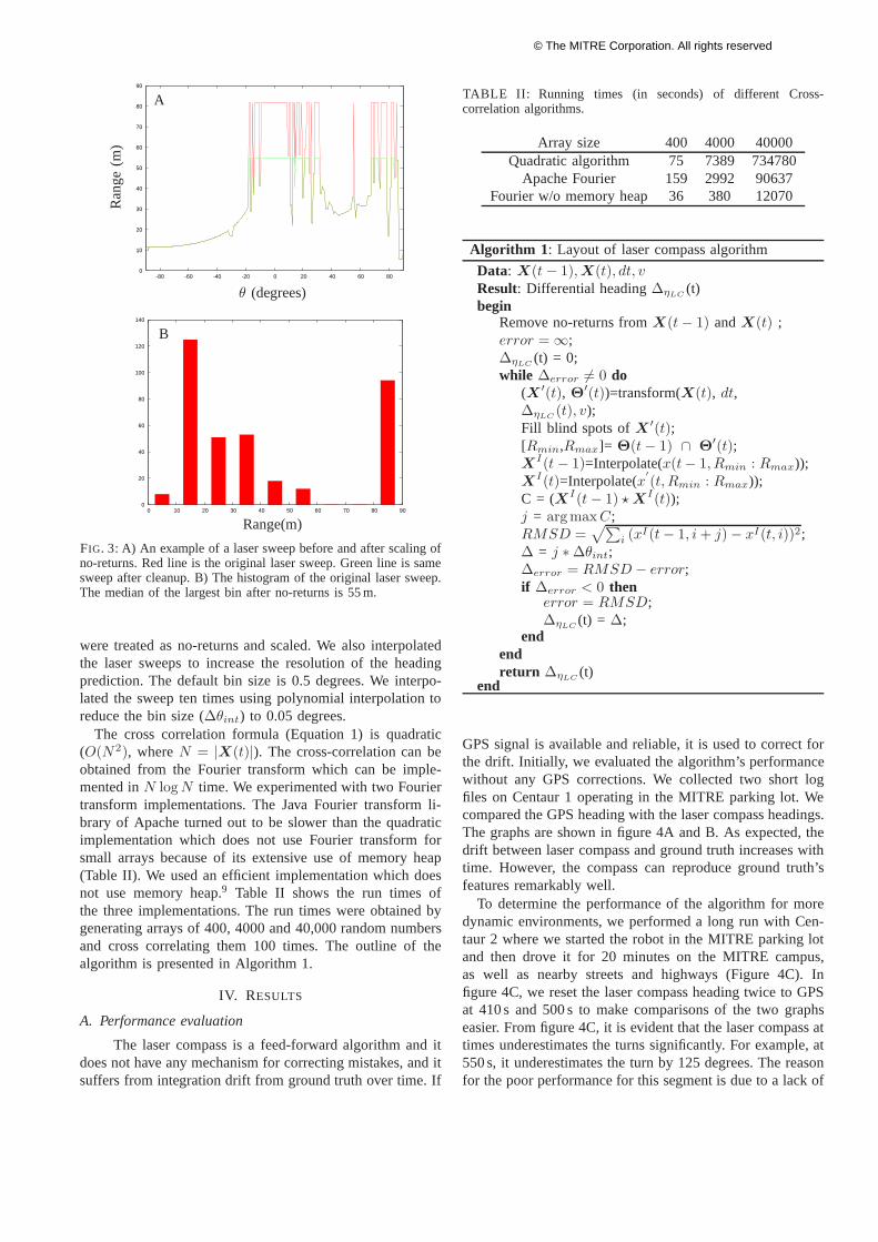
Centaurs operate outdoors in a dynamic environment.LMS record the environment in polar coordinates, and ob-jects that are at the same distance from the vehicles registeron a parabola. An exception is a no-return. When the laserray is lost due to hitting a black, shiny object or the horizon,the recorder registers the maximum possible distance, whichis 81.9 m regardless of the angular orientation of the laserbeam. We call these values no-returns.
No-returns throw off the correlation sum. Because a no-return is the largest value in the distance space of the SICKlasers, when there is a significant number of them present, thecorrelation function will correlate the no-returns as opposedto everything else. Depending on the environment, a greatnumber of recordings can be no-returns as shown in asweep histogram in figure 3B. Removing no-returns fromthe sweeps produced low-quality algorithm performance, asdid removing them and interpolating between the remainingpoints with a number of different interpolation methods. Webelieve this is because no-returns provide information aboutthe environment. If they correspond to the horizon or a largeblack car, they keep their relative location on two consecutivescans.
The following procedure proved successful. First, weremoved all isolated no-returns. We calculated the histogramof the sweep and set all the no-returns to the median ofthe second largest histogram bin. An example is shown infigure 3.
D. Implementation notes
When the laser scans an obstacle att− 1, it has moreinformation about the environment behind the obstacle thanit does at timet. When the sweep at timet is transformedto t − 1 it will have a wider field of view around obstacles,but no information about this environment. These blind spots
© The MITRE Corporation. All rights reserved
0
20
40
60
80
100
120
140
0 10 20 30 40 50 60 70 80 90
0
10
20
30
40
50
60
70
80
90
-80 -60 -40 -20 0 20 40 60 80
θ (degrees)
Ra
ng
e(m
)
Range(m)
A
B
FIG. 3: A) An example of a laser sweep before and after scaling ofno-returns. Red line is the original laser sweep. Green line is samesweep after cleanup. B) The histogram of the original laser sweep.The median of the largest bin after no-returns is 55 m.
were treated as no-returns and scaled. We also interpolatedthe laser sweeps to increase the resolution of the headingprediction. The default bin size is 0.5 degrees. We interpo-lated the sweep ten times using polynomial interpolation toreduce the bin size (∆θint) to 0.05 degrees.
The cross correlation formula (Equation 1) is quadratic(O(N2), whereN = |X(t)|). The cross-correlation can beobtained from the Fourier transform which can be imple-mented inN log N time. We experimented with two Fouriertransform implementations. The Java Fourier transform li-brary of Apache turned out to be slower than the quadraticimplementation which does not use Fourier transform forsmall arrays because of its extensive use of memory heap(Table II). We used an efficient implementation which doesnot use memory heap.9 Table II shows the run times ofthe three implementations. The run times were obtained bygenerating arrays of 400, 4000 and 40,000 random numbersand cross correlating them 100 times. The outline of thealgorithm is presented in Algorithm 1.
IV. RESULTS
A. Performance evaluation
The laser compass is a feed-forward algorithm and itdoes not have any mechanism for correcting mistakes, and itsuffers from integration drift from ground truth over time. If
TABLE II: Running times (in seconds) of different Cross-correlation algorithms.
Array size 400 4000 40000Quadratic algorithm 75 7389 734780
Apache Fourier 159 2992 90637Fourier w/o memory heap 36 380 12070
Algorithm 1 : Layout of laser compass algorithm
Data: X(t − 1), X(t), dt, vResult: Differential heading∆ηLC
(t)begin
Remove no-returns fromX(t − 1) andX(t) ;error = ∞;∆ηLC
(t) = 0;while ∆error 6= 0 do
(X ′(t), Θ′(t))=transform(X(t), dt,
∆ηLC(t), v);
Fill blind spots ofX ′(t);[Rmin,Rmax]= Θ(t − 1) ∩ Θ
′(t);X
I(t − 1)=Interpolate(x(t− 1, Rmin : Rmax));X
I(t)=Interpolate(x′
(t, Rmin : Rmax));C = (XI(t − 1) ⋆ X
I(t));j = argmax C;RMSD =
√∑
i (xI(t − 1, i + j) − xI(t, i))2;∆ = j ∗ ∆θint;∆error = RMSD − error;if ∆error < 0 then
error = RMSD;∆ηLC
(t) = ∆;end
endreturn ∆ηLC
(t)end
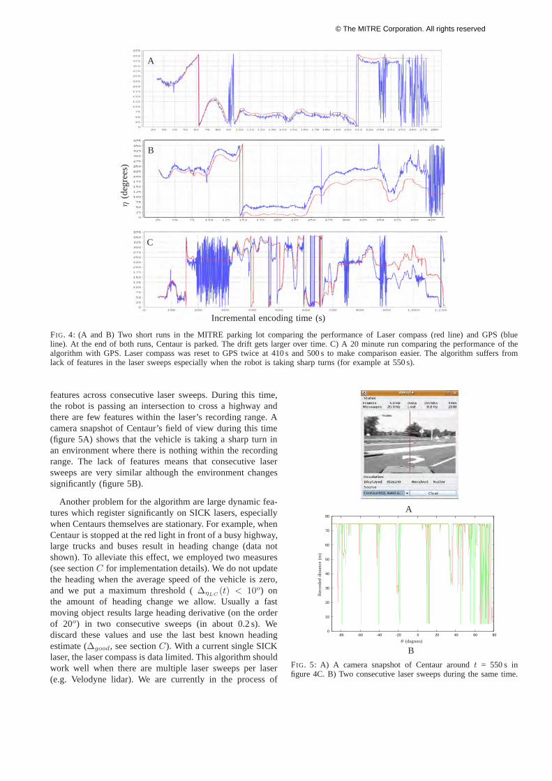
GPS signal is available and reliable, it is used to correct forthe drift. Initially, we evaluated the algorithm’s performancewithout any GPS corrections. We collected two short logfiles on Centaur 1 operating in the MITRE parking lot. Wecompared the GPS heading with the laser compass headings.The graphs are shown in figure 4A and B. As expected, thedrift between laser compass and ground truth increases withtime. However, the compass can reproduce ground truth’sfeatures remarkably well.
To determine the performance of the algorithm for moredynamic environments, we performed a long run with Cen-taur 2 where we started the robot in the MITRE parking lotand then drove it for 20 minutes on the MITRE campus,as well as nearby streets and highways (Figure 4C). Infigure 4C, we reset the laser compass heading twice to GPSat 410 s and 500 s to make comparisons of the two graphseasier. From figure 4C, it is evident that the laser compass attimes underestimates the turns significantly. For example, at550 s, it underestimates the turn by 125 degrees. The reasonfor the poor performance for this segment is due to a lack of
© The MITRE Corporation. All rights reserved
A
B
C
η(d
egre
es)
Incremental encoding time (s)
FIG. 4: (A and B) Two short runs in the MITRE parking lot comparing the performance of Laser compass (red line) and GPS (blueline). At the end of both runs, Centaur is parked. The drift gets larger over time. C) A 20 minute run comparing the performance of thealgorithm with GPS. Laser compass was reset to GPS twice at 410 s and 500 s to make comparison easier. The algorithm suffers fromlack of features in the laser sweeps especially when the robot is taking sharp turns (for example at 550 s).
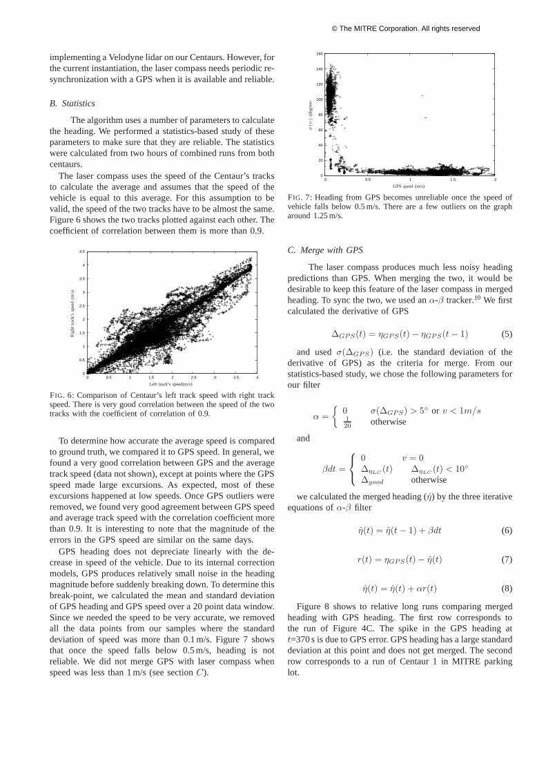
features across consecutive laser sweeps. During this time,the robot is passing an intersection to cross a highway andthere are few features within the laser’s recording range. Acamera snapshot of Centaur’s field of view during this time(figure 5A) shows that the vehicle is taking a sharp turn inan environment where there is nothing within the recordingrange. The lack of features means that consecutive lasersweeps are very similar although the environment changessignificantly (figure 5B).
Another problem for the algorithm are large dynamic fea-tures which register significantly on SICK lasers, especiallywhen Centaurs themselves are stationary. For example, whenCentaur is stopped at the red light in front of a busy highway,large trucks and buses result in heading change (data notshown). To alleviate this effect, we employed two measures(see sectionC for implementation details). We do not updatethe heading when the average speed of the vehicle is zero,and we put a maximum threshold (∆ηLC
(t) < 10o) onthe amount of heading change we allow. Usually a fastmoving object results large heading derivative (on the orderof 20o) in two consecutive sweeps (in about 0.2 s). Wediscard these values and use the last best known headingestimate (∆good, see sectionC). With a current single SICKlaser, the laser compass is data limited. This algorithm shouldwork well when there are multiple laser sweeps per laser(e.g. Velodyne lidar). We are currently in the process of
0
10
20
30
40
50
60
70
80
-80 -60 -40 -20 0 20 40 60 80
θ (degrees)
Rec
ord
edd
ista
nce
(m)
B
A
FIG. 5: A) A camera snapshot of Centaur aroundt = 550 s infigure 4C. B) Two consecutive laser sweeps during the same time.
© The MITRE Corporation. All rights reserved
implementing a Velodyne lidar on our Centaurs. However, forthe current instantiation, the laser compass needs periodic re-synchronization with a GPS when it is available and reliable.
B. Statistics
The algorithm uses a number of parameters to calculatethe heading. We performed a statistics-based study of theseparameters to make sure that they are reliable. The statisticswere calculated from two hours of combined runs from bothcentaurs.
The laser compass uses the speed of the Centaur’s tracksto calculate the average and assumes that the speed of thevehicle is equal to this average. For this assumption to bevalid, the speed of the two tracks have to be almost the same.Figure 6 shows the two tracks plotted against each other. Thecoefficient of correlation between them is more than 0.9.
0
0.5
1
1.5
2
2.5
3
3.5
4
4.5
0 0.5 1 1.5 2 2.5 3 3.5 4
Rig
ht
trac
k’s
spee
d(m
/s)
Left track’s speed(m/s)
FIG. 6: Comparison of Centaur’s left track speed with right trackspeed. There is very good correlation between the speed of the twotracks with the coefficient of correlation of 0.9.
To determine how accurate the average speed is comparedto ground truth, we compared it to GPS speed. In general, wefound a very good correlation between GPS and the averagetrack speed (data not shown), except at points where the GPSspeed made large excursions. As expected, most of theseexcursions happened at low speeds. Once GPS outliers wereremoved, we found very good agreement between GPS speedand average track speed with the correlation coefficient morethan 0.9. It is interesting to note that the magnitude of theerrors in the GPS speed are similar on the same days.
GPS heading does not depreciate linearly with the de-crease in speed of the vehicle. Due to its internal correctionmodels, GPS produces relatively small noise in the headingmagnitude before suddenly breaking down. To determine thisbreak-point, we calculated the mean and standard deviationof GPS heading and GPS speed over a 20 point data window.Since we needed the speed to be very accurate, we removedall the data points from our samples where the standarddeviation of speed was more than 0.1 m/s. Figure 7 showsthat once the speed falls below 0.5 m/s, heading is notreliable. We did not merge GPS with laser compass whenspeed was less than 1 m/s (see sectionC).
0
20
40
60
80
100
120
140
160
0 0.5 1 1.5 2
σ(ν)
(deg
rees
GPS speed (m/s)
FIG. 7: Heading from GPS becomes unreliable once the speed ofvehicle falls below 0.5 m/s. There are a few outliers on the grapharound 1.25 m/s.
C. Merge with GPS
The laser compass produces much less noisy headingpredictions than GPS. When merging the two, it would bedesirable to keep this feature of the laser compass in mergedheading. To sync the two, we used anα-β tracker.10 We firstcalculated the derivative of GPS
∆GPS(t) = ηGPS(t) − ηGPS(t − 1) (5)
and usedσ(∆GPS) (i.e. the standard deviation of thederivative of GPS) as the criteria for merge. From ourstatistics-based study, we chose the following parameters forour filter
α =
{
0 σ(∆GPS) > 5◦ or v < 1m/s120 otherwise
and
βdt =
0 v = 0∆ηLC
(t) ∆ηLC(t) < 10◦
∆good otherwise
we calculated the merged heading (η̂) by the three iterativeequations ofα-β filter
η̂(t) = η̂(t − 1) + βdt (6)
r(t) = ηGPS(t) − η̂(t) (7)
η̂(t) = η̂(t) + αr(t) (8)
Figure 8 shows to relative long runs comparing mergedheading with GPS heading. The first row corresponds tothe run of Figure 4C. The spike in the GPS heading att=370 s is due to GPS error. GPS heading has a large standarddeviation at this point and does not get merged. The secondrow corresponds to a run of Centaur 1 in MITRE parkinglot.
© The MITRE Corporation. All rights reserved

A
B
η(d
egre
es)
Incremental encoding time (s)
FIG. 8: Merged heading for two runs. A) long run of Centaur 2 in figure 4C. The GPS spike att = 370 s has a largeσ and it does notget incorporated to the merged heading. B) A run of Centaur 1 on MITRE parking lot.
V. CONCLUSIONS
This paper presents an on-line algorithm that usesSICK laser scans and cross-correlation function to improvethe heading predictions of GPS in UGVs. The algorithmproduces heading that has higher signal to noise ratio thanthat of GPS alone.
There has been extensive work in the field of simulta-neous localization and mapping (SLAM).11], [12 Algorithmsthat solve SLAM, provide not only heading, but also thedisplacement along the x and y direction, as well as the mapof the environment. However, SLAM algorithms are usuallycomputationally expensive and have various shortcomings. IfGPS is available and reliable, it out-performs SLAM algo-rithms in localization. However, GPS suffers from outagesand high signal to noise ratio at low speeds or spikes. In thispaper, we have addressed these issues.
Our algorithm can also be used to improve the per-formance of motion models. In most motion models, thenew x and y displacement are determined from heading byprojecting the heading onto the x and y coordinates. If thereis no means of heading prediction available, the headingis drawn from a random distribution. This ties the motionmodel to the type of the distribution picked and whether theassumption is valid. The error in heading can propagate tox and y displacement and result in poor localization. Usinglaser compass as a source of heading as opposed a randomlysampling it from a probability distribution can improve thequality of motion models significantly. We are in the processof implementing this concept for Centaurs.
REFERENCES
[1] J. Kosecka and W. Zhang, “Video compass,”7th European Conferenceon Computer Vision, pp. 476–491, 2002.
[2] A. Makadia, C. Geyer, S. S. Sastry, and K. Danillidis, “Radon-basedstructure from motion without correspondences.”IEEE Conference onComputer Vision and Pattern Recognition., pp. 796–803, 2005.
[3] J. M. M. Montiel and A. J. Davison, “A visual compass based onslam,” IEEE international Conference on Robotics and Automation,pp. 2403–2408, 2007.
[4] R. J. Garbowski, R. M. Weatherly, R. H. Bolling, D. Seidel, M. Shadid,and A. Jones, “Mitre meteor: An off-road autonomous vehicle fordarpa’s grand challenge.”Journal of field Robotics, special issue onthe DARPA grand challenge.
[5] R. Bolling, R. Garbowski, A. Jones, M. Shadid, and R. Weatherly,“The mitre meteorites 2005 darpa grand challenge entry,”http://www.darpa.mil/grandchallenge05/TechPapers/MITREMeteorites.pdf.
[6] C. Cicalese, R. M. Weatherly, J. Sherrill, R. H. Bolling, K. Forbes,R. J. Grabowski, K. Ring, and S. Seidel, “A distributed, multi-languagearchitecture for large unmanned ground vehicles.”Proceedings ofthe 2008 ACM annual international conference on SIGAda annualinternational conference., pp. 133–138, 2008.
[7] R. M. Weatherly, F. S. Kuhl, R. H. Bolling, and R. J. Grabowski,“The mitre meteor robot control software: Simulate as you operate.”Proceedings of the 38th Winter Simulation Conference Dec. 3-6, pp.1294–1298, 2006.
[8] R. M. Weatherly and E. H. Page, “Efficient process interactionsimulation in java: Implementing co-routines within a single javathread.” Proceedings of the 36th Winter Simulation Conference Dec5-8, pp. 1437–1443, 2004.
[9] Http://cnx.rice.edu/content/m12016/latest/.[10] T. L. Ogle and W. D. Blair, “Fixed-lag alpha-beta filter for target
trajectory smoothing,”IEEE Transactions on Aerospace and ElectronicSystems, pp. 1417 – 1421, 2004.
[11] H. Durrant-Whyte and T. Bailey, “Simultaneous localisation andmapping (slam): Part i the essential algorithms,”IEEE Robotics andAutomation Magazine, vol. 13, p. 99110, 2006.
[12] ——, “Simultaneous localisation and mapping (slam):part ii state ofthe art,” IEEE Robotics and Automation Magazine, vol. 13, pp. 108–117, 2006.
© The MITRE Corporation. All rights reserved