Embed Size (px)
Citation preview

UQ Engineering
Faculty of Engineering, Architecture and Information Technology
THE UNIVERSITY OF QUEENSLAND
Bachelor of Engineering Thesis
Design of the Interior Door Panels in a 1969 Chevrolet Camaro
Student Name: Aarash MAJOO
Course Code: MECH4500
Supervisor: Dr. Luigi Vandi
Submission date: 28 October 2016
A thesis submitted in partial fulfilment of the requirements of the
Bachelor of Engineering degree in Mechanical Engineering

MECH4500 – Final Report
Page | iii
Abstract
A client approached the university to aid in the design of the interior door panels on their reimagined version
of a 1969 Chevrolet Camaro. Detailed within this report is a completed design for both the driver and passenger
side door panels, as well as the results of static load testing. The final deliverable product to the client was a
CAD file containing the design, which would then be manufactured using 3D printing.
The client had specific design requirements - that the interior design should mirror the exterior theme of the
vehicle and should not be something that is available on the mass market. To gain an understanding of the
market, prior art research was conducted on original and remodelled 1969 Camaro interiors. The results of this
research showed that the most aesthetically pleasing designs were simple, clean and had curved surfaces rather
than straight edges. This helped to give an impression of a fast, menacing vehicle which the client desired.
Due to the manufacturing process of 3D printing, dimensional accuracy was important. To facilitate this
necessity, the interior was 3D scanned using a Faro Arm before being processed into a CAD file. The
processing required three main stages – noise reduction, creation of surfaces and shapes and assembly of
individual components into one main file. Using this completed CAD file, a traced model of the interior of the
vehicle was used as a blank block upon which the designs could be created.
There were three iterations of the door panel produced, with client feedback being the main source of change
between each of the designs. They wished for the door panels to be objects that were sleek and slim, looked
good and did not detract from the attraction of the interior dashboard and console. To meet this request, a focus
was put on flow – to allow there to be a seamless continuation from the dashboard to the door panels. The
panel was kept simplistic by only including necessary features, such as a door lever, electronic window buttons
as well as an arm rest - which was a functional feature as well as the main aesthetic feature.
On completion of design, static load testing was conducted through the use of Finite Element Modelling
(FEM). Through client input, the material of choice was narrowed down to fiberglass as it was cost effective
to produce, did not require a special 3D printer and was easy to add a design to. The method of attachment was
chosen to be an industrial strength glue, which had been used for purposes similar to this. For FEM analysis,
the panel was modelled as fixed on the back panel, as the glue would be applied to the perimeter before being
secured to the frame of the car.
In the analysis, two loading cases were identified – a point load and a uniformly distributed load across the
length of the arm rest. These were found to be the most likely scenarios of forces being applied, usually when
the driver would enter or exit the vehicle. For the simulation, a driver mass of 120kg was used with an applied
safety factor of 1.5 for the simulation. The results of the simulations showed that the areas of maximum stress
concentration for both loading cases were through the centre section of the arm rest, which was provided with
the most support in the design phase.
The design created in this report will be provided to the client as it has fulfilled the outlined requirements.
MECH4500 – Final Report
Page | iv
Table of Contents
1 Introduction ............................................................................................................................................... 1
2 Scope of the Project ................................................................................................................................... 2
3 Background Research ................................................................................................................................ 2
3.1 The Client .......................................................................................................................................... 2
3.2 Prior Art ............................................................................................................................................. 3
3.2.1 Original 1969 Chevrolet Camaro Door Interiors ....................................................................... 3
3.2.2 Existing 1969 Camaro remakes ................................................................................................. 4
3.2.3 Current road/Model car interiors ............................................................................................... 5
3.3 3D Scanning ...................................................................................................................................... 6
3.4 Material Selection .............................................................................................................................. 6
3.5 3D Printing Design Considerations ................................................................................................... 7
4 3D Scanning and Processing ..................................................................................................................... 8
4.1 Scanning Process ............................................................................................................................... 8
4.2 Creation of a CAD file....................................................................................................................... 9
4.2.1 Reducing Noise.......................................................................................................................... 9
4.2.2 Creating Surfaces and Shapes .................................................................................................... 9
4.2.3 Assembly of individual CAD models ...................................................................................... 10
5 Design of the Interior Door Panels .......................................................................................................... 12
5.1 Preliminary Design .......................................................................................................................... 12
5.1.1 Difficulties in Preliminary design ............................................................................................ 14
5.1.2 Client Feedback ....................................................................................................................... 14
5.2 Design Iteration Two ....................................................................................................................... 15
5.2.1 Complete 3D Model ................................................................................................................ 15
5.2.2 Design ...................................................................................................................................... 15
5.2.3 Design Creation ....................................................................................................................... 17
5.2.4 Client Feedback ....................................................................................................................... 17
5.3 Final Design Features ...................................................................................................................... 18
MECH4500 – Final Report
Page | v
5.3.1 Arm Rest .................................................................................................................................. 18
5.3.2 Curvature of the panel ............................................................................................................. 19
5.3.3 Door Handle ............................................................................................................................ 19
5.3.4 Power Window Switches ......................................................................................................... 19
5.3.5 Fillets and Other Features ........................................................................................................ 20
5.3.6 Exclusions ................................................................................................................................ 20
5.4 Trim and Colour Scheme ................................................................................................................. 20
6 Finite Element Modelling (FEM) ............................................................................................................ 23
6.1 Material Selection ............................................................................................................................ 23
6.2 Attachment method ......................................................................................................................... 23
6.3 Loading Cases ................................................................................................................................. 24
6.3.1 Point Load ............................................................................................................................... 24
6.3.2 Uniformly Distributed Load (UDL) ........................................................................................ 24
6.4 Meshing ........................................................................................................................................... 25
6.5 Simulation Results ........................................................................................................................... 26
7 Conclusion and Recommendations ......................................................................................................... 27
7.1 Recommendations ........................................................................................................................... 29
8 Bibliography ............................................................................................................................................ 30
9 Appendices .............................................................................................................................................. 32
9.1 Appendix A – Images of bare vehicle ............................................................................................. 32
9.2 Appendix B – Preliminary Design screenshots ............................................................................... 33
9.3 Appendix C – Secondary Design Additional Images ...................................................................... 34
9.4 Appendix D – Final Design Additional Images .............................................................................. 35
9.5 Appendix E - Fiberglass Material Properties................................................................................... 36
MECH4500 – Final Report
Page | vi
List of Figures
Figure 1: Suede driver side door panels on a 1969 Camaro .............................................................................. 3
Figure 2: Leather driver side door panels on a 1969 Camaro ............................................................................ 3
Figure 3: Passenger side door panel design 1 .................................................................................................... 4
Figure 4: Passenger side door panel design 2 .................................................................................................... 4
Figure 5: Bugatti Veyron door panel ................................................................................................................. 5
Figure 6: Lamborghini Aventador door panel ................................................................................................... 5
Figure 7: Raw point cloud data from 3D scan ................................................................................................... 9
Figure 8: Surface Primitives function creating a cylinder ............................................................................... 10
Figure 9: Two different scans of the interior door frame with marked reference points ................................. 10
Figure 10: Completed 3D scan of driver side car door .................................................................................... 11
Figure 11: Assembled complete scan of interior ............................................................................................. 11
Figure 12: Initial extrusion from 3D Scan ....................................................................................................... 12
Figure 13: Ideas of the client sketched on tracing paper ................................................................................. 13
Figure 14: Preliminary Design ........................................................................................................................ 13
Figure 15: Model from created from 3D scan tracing ..................................................................................... 15
Figure 16: Left – Left side view of second design. Right – Angled view. ...................................................... 16
Figure 17: Sketches to produce Arm Rest ....................................................................................................... 17
Figure 18: Left – Left side view of final design. Right – Angled view. .......................................................... 18
Figure 19: Sketches of arm rest ....................................................................................................................... 18
Figure 20: Left side view of the door .............................................................................................................. 19
Figure 21: Door Handle Design....................................................................................................................... 19
Figure 22: Power window switches ................................................................................................................. 19
Figure 23: Additional aesthetic features .......................................................................................................... 20
Figure 24: Completed Driver Side and Passenger Door Panels ...................................................................... 21
Figure 25: Interior 3D scan with designed driver's side door panel ................................................................ 22
Figure 26: Point Load applied to arm rest ....................................................................................................... 24
Figure 27: Pressure (UDL) load applied to arm rest........................................................................................ 24
Figure 28: Meshing of the door panel ............................................................................................................. 25
Figure 29: Left - Point Load Analysis, Right - UDL Analysis ........................................................................ 26
Figure 30: Bare interior of a 1969 Chevrolet Camaro ..................................................................................... 32
Figure 31: Initial design left side drivers side view ......................................................................................... 33
Figure 32: Rendered front on view .................................................................................................................. 33
Figure 33: Secondary design right side view ................................................................................................... 34
Figure 34: Secondary Design Front on view ................................................................................................... 34
Figure 35: Final design right side view ........................................................................................................... 35
Figure 36: Final design front on view ............................................................................................................. 35
MECH4500 – Final Report
1
1 Introduction
A client has approached the university with the request of having a student design the interior door
panels on his reimagined version of a 1969 Chevrolet Camaro. With the designed door panels, he
intends to have it manufactured and eventually installed on the vehicle. The student is to create the door
panels with their own design, such that they learn from the process and for them to gain an
understanding of the manufacturing automotive industry.
The car currently is retaining the original chassis of a 1969 Camaro, however has been slightly widened
to allow for the addition of a larger engine than the original. As it lies, the inside of the car is completely
bare, displaying all the structural components upon which the door panels of the car are to be designed
(bare vehicle image available in Appendix A). Being able to see the body will work as an advantage
when creating the design, as it facilitates the acquisition of all required sizing and part locations.
Due to the limitations of alternatives within the industry, the client’s chosen method of manufacturing
is to 3D print the design. Since this method of manufacture requires precise and accurate dimensions,
the panels are 3D scanned and processed to create a CAD model of the interior of the vehicle. Using
this model, it is then possible to be confident with dimensions when designing the panels and will lead
to a manufacturing product that will fit exactly onto the vehicle.
While the design is meant to be that of the students, the client will still have an input upon what he
believes is a design that meets his requirements. Due to the importance of understanding the client’s
perspective, an in-depth prior art study is also conducted to investigate pre-existing work that has been
completed on 1969 Camaros. Using the literature as a baseline, a design can then be built up to the
standard the client desires with the student’s own interpretation and input.
With a completed design, it is also important to test the structural integrity of the panel through any
different loading scenarios that might occur with the use of the vehicle. To facilitate this testing, finite
element modelling (FEM) software will be employed to see if the design can withstand all expected
loading cases. This includes selection of materials, meshing and points of fixture onto the vehicle.
The main goal of this project is to explore an innovative method for the production of unique parts that
fit into pre-existing structures. In order to explore this, a bare 1969 Chevrolet Camaro is used as the
existing structure, upon which door panels will be designed with the intention of eventual production.
The new method described is one using a 3D scanner to produce an accurate CAD model of the
structure, which will then be used to create a design. To do this, specialized scanning equipment and
software will be used, including Autodesk Inventor 2017.
At the completion of this project, the final deliverable product to the client will be a CAD file which
can be used in the manufacturing of the part.
MECH4500 – Final Report
2
2 Scope of the Project
This report was limited in its focus to mainly the design and testing of the door panels with the specific
parts that will and will not be investigated outlined below.
Table 1: Scope of the project
In Scope Out of Scope
Research into pre-existing design options Colouring/trim of door panels
3D Scanning of vehicle interior Rubber seal on door panels
Processing of 3D scan to produce CAD file Vibrational testing
Design of driver and passenger door panels Heat loading testing
Material Selection Electric window mechanism
Attachment Method Door locking system
Static Load testing Detailed production method process
Fulfilment of Australian Standards (model car)
3 Background Research
3.1 The Client
As with any project, it is important to know what the client wants the outcome to be. In this case, a key
consideration is to understand the background of the client himself and how his own work impacts the
pending design.
The client is by trade, very experienced in designing the interiors of cars by hand. They are well known
for designing, manufacturing and fitting unique designs to specific muscle cars, many of which have
gone on to win awards. They have expressed a wish that the design to be created should be something
that is unique in itself, and while it may encompass features from existing vehicles, overall should be
something that is not currently available in the mass market.
In terms of the design itself, they have also expressed their idea of the car to be a mix of both the old
style of Camaro, with futuristic aspects also associated with it. For example, the headlights and tail
lights are going to be LEDs, which fits the old Camaro chassis with a new type of technology, allowing
for a mix between the old and new. For the interior, there should be a similar theme in which a futuristic
design is built into the pre-existing old shape of chassis, to give the car an exciting, innovative look.
MECH4500 – Final Report
3
3.2 Prior Art
3.2.1 Original 1969 Chevrolet Camaro Door Interiors
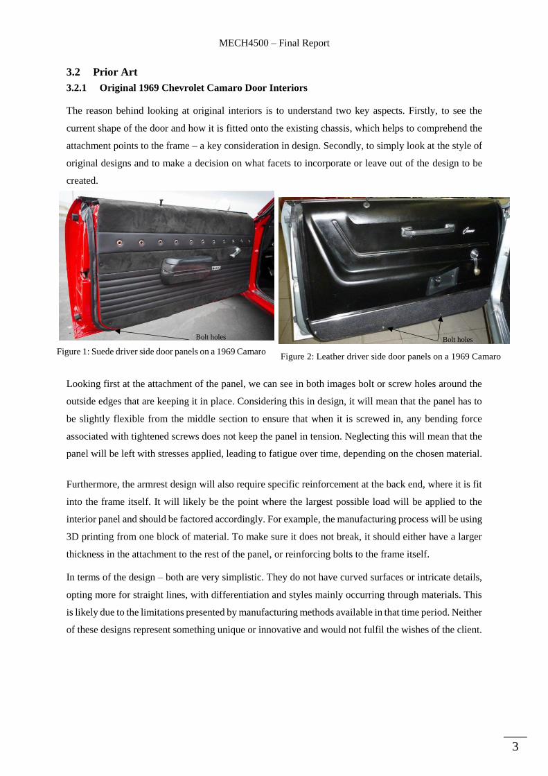
The reason behind looking at original interiors is to understand two key aspects. Firstly, to see the
current shape of the door and how it is fitted onto the existing chassis, which helps to comprehend the
attachment points to the frame – a key consideration in design. Secondly, to simply look at the style of
original designs and to make a decision on what facets to incorporate or leave out of the design to be
created.
Looking first at the attachment of the panel, we can see in both images bolt or screw holes around the
outside edges that are keeping it in place. Considering this in design, it will mean that the panel has to
be slightly flexible from the middle section to ensure that when it is screwed in, any bending force
associated with tightened screws does not keep the panel in tension. Neglecting this will mean that the
panel will be left with stresses applied, leading to fatigue over time, depending on the chosen material.
Furthermore, the armrest design will also require specific reinforcement at the back end, where it is fit
into the frame itself. It will likely be the point where the largest possible load will be applied to the
interior panel and should be factored accordingly. For example, the manufacturing process will be using
3D printing from one block of material. To make sure it does not break, it should either have a larger
thickness in the attachment to the rest of the panel, or reinforcing bolts to the frame itself.
In terms of the design – both are very simplistic. They do not have curved surfaces or intricate details,
opting more for straight lines, with differentiation and styles mainly occurring through materials. This
is likely due to the limitations presented by manufacturing methods available in that time period. Neither
of these designs represent something unique or innovative and would not fulfil the wishes of the client.
Figure 1: Suede driver side door panels on a 1969 Camaro Figure 2: Leather driver side door panels on a 1969 Camaro
Bolt holes Bolt holes

MECH4500 – Final Report
4
3.2.2 Existing 1969 Camaro remakes
In the interest of once again aligning with the clients wishes, the next step is to look at existing Camaro
remakes, to see designs that exist currently in the market. This will mean that new, creative design
features can be used from these cars, while once again ensuring that there is a uniqueness to the panels
designed in this thesis. When researching, many different designs were found for 1969 Camaro’s that
had been refurbished. Most of them had the same design as in Figure 1, however with newer materials
or product applied, to make them look more aesthetically pleasing. The following images were designs
found to be different to the originals, but those that also were fit onto the same chassis frame.
Without having previous knowledge, by simple comparison it is immediately apparent that Figures 3 &
4 are of newer designs to that of Figures 1 & 2. When reflecting on why this is so, it once again relates
to the advancement in technologies associated with manufacturing. Figures 3 & 4 are designs which
contain more complex geometry, having slightly curved edges and shapes that give these doors a newer
feel to them. This is one aspect of these designs that can be taken into consideration when designing the
interior panels, whereby a futuristic feel is associated with shapes that are not the normal simplistic
straight lines, but those that are more curved.
Furthermore, in terms of fit onto the chassis door frame, Figures 3 & 4 have a much better sealing
technique between the frame on the side of the door, to the actual panel itself. The rubber is completely
covering all of the opening, as opposed to Figure 1 where there is a visible gap. When designing the
panels, a consideration for the gap thickness for the seal will also have to be considered. This will ensure
that none of the electronics inside the door will be damaged.
Figure 3: Passenger side door panel design 1 Figure 4: Passenger side door panel design 2
MECH4500 – Final Report
5
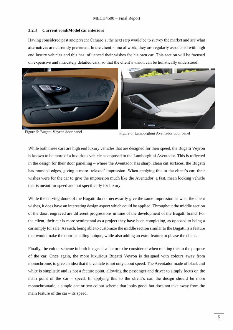
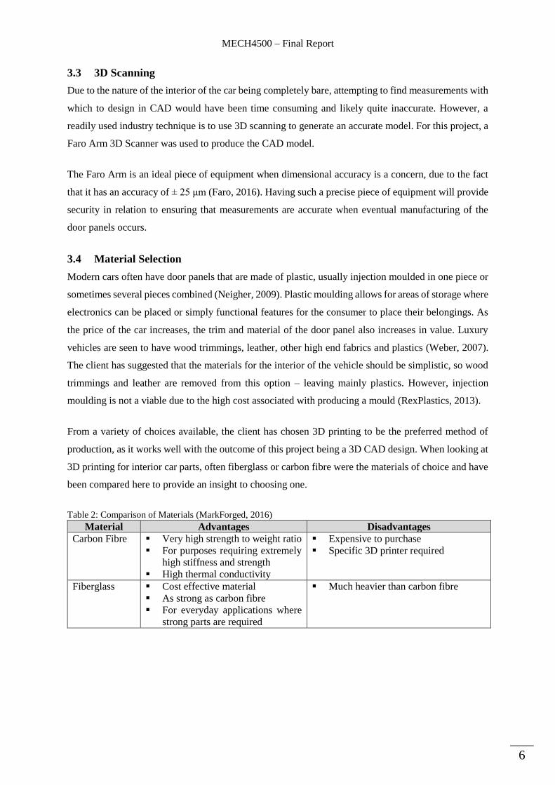
3.2.3 Current road/Model car interiors
Having considered past and present Camaro’s, the next step would be to survey the market and see what
alternatives are currently presented. In the client’s line of work, they are regularly associated with high
end luxury vehicles and this has influenced their wishes for his own car. This section will be focused
on expensive and intricately detailed cars, so that the client’s vision can be holistically understood.
While both these cars are high end luxury vehicles that are designed for their speed, the Bugatti Veyron
is known to be more of a luxurious vehicle as opposed to the Lamborghini Aventador. This is reflected
in the design for their door panelling – where the Aventador has sharp, clean cut surfaces, the Bugatti
has rounded edges, giving a more ‘relaxed’ impression. When applying this to the client’s car, their
wishes were for the car to give the impression much like the Aventador, a fast, mean looking vehicle
that is meant for speed and not specifically for luxury.
While the curving doors of the Bugatti do not necessarily give the same impression as what the client
wishes, it does have an interesting design aspect which could be applied. Throughout the middle section
of the door, engraved are different progressions in time of the development of the Bugatti brand. For
the client, their car is more sentimental as a project they have been completing, as opposed to being a
car simply for sale. As such, being able to customize the middle section similar to the Bugatti is a feature
that would make the door panelling unique, while also adding an extra feature to please the client.
Finally, the colour scheme in both images is a factor to be considered when relating this to the purpose
of the car. Once again, the more luxurious Bugatti Veyron is designed with colours away from
monochrome, to give an idea that the vehicle is not only about speed. The Aventador made of black and
white is simplistic and is not a feature point, allowing the passenger and driver to simply focus on the
main point of the car – speed. In applying this to the client’s car, the design should be more
monochromatic, a simple one or two colour scheme that looks good, but does not take away from the
main feature of the car – its speed.
Figure 5: Bugatti Veyron door panel Figure 6: Lamborghini Aventador door panel
MECH4500 – Final Report
6
3.3 3D Scanning
Due to the nature of the interior of the car being completely bare, attempting to find measurements with
which to design in CAD would have been time consuming and likely quite inaccurate. However, a
readily used industry technique is to use 3D scanning to generate an accurate model. For this project, a
Faro Arm 3D Scanner was used to produce the CAD model.
The Faro Arm is an ideal piece of equipment when dimensional accuracy is a concern, due to the fact
that it has an accuracy of ± 25 μm (Faro, 2016). Having such a precise piece of equipment will provide
security in relation to ensuring that measurements are accurate when eventual manufacturing of the
door panels occurs.
3.4 Material Selection
Modern cars often have door panels that are made of plastic, usually injection moulded in one piece or
sometimes several pieces combined (Neigher, 2009). Plastic moulding allows for areas of storage where
electronics can be placed or simply functional features for the consumer to place their belongings. As
the price of the car increases, the trim and material of the door panel also increases in value. Luxury
vehicles are seen to have wood trimmings, leather, other high end fabrics and plastics (Weber, 2007).
The client has suggested that the materials for the interior of the vehicle should be simplistic, so wood
trimmings and leather are removed from this option – leaving mainly plastics. However, injection
moulding is not a viable due to the high cost associated with producing a mould (RexPlastics, 2013).
From a variety of choices available, the client has chosen 3D printing to be the preferred method of
production, as it works well with the outcome of this project being a 3D CAD design. When looking at
3D printing for interior car parts, often fiberglass or carbon fibre were the materials of choice and have
been compared here to provide an insight to choosing one.
Table 2: Comparison of Materials (MarkForged, 2016)
Material Advantages Disadvantages
Carbon Fibre Very high strength to weight ratio
For purposes requiring extremely
high stiffness and strength
High thermal conductivity
Expensive to purchase
Specific 3D printer required
Fiberglass Cost effective material
As strong as carbon fibre
For everyday applications where
strong parts are required
Much heavier than carbon fibre
MECH4500 – Final Report
7
3.5 3D Printing Design Considerations
Having decided that the design will be 3D printed, it is also significant to know characteristics of design
that allow for a successful production process. Research highlights four important features that should
be adhered to when manufacturing a component by 3D printing.
i. Components should be ‘watertight’ – this refers to having no small gaps that may
unintentionally occur from incorrect sketching or extrusions
ii. Non-manifold objects – this is defined as an object which has an edge that is shared between
more than two faces. This is unlikely to occur on the door panels as it is one main component
and will not have separate adjoining components linking to it, that might cause shared edges.
iii. Minimum wall thickness – this is to ensure that the printer will be able to physically create the
object and is largely dependent on the material. (3D Creation Lab, 2016)
iv. Overhangs/holes – in 3D printing, parts are printed one on top of the other. As such, if there are
two surfaces in the design that have an empty gap between them, the print will fail. To ensure
that this will not occur, design so that all the components are joined together (Donley, 2014)
With an understanding and application of these conditions, confidence can be drawn in the design that
is produced.

MECH4500 – Final Report
8
4 3D Scanning and Processing
The final goal for the client is to produce the panel designed within this report and fit it onto their
vehicle. To produce this, the dimensions that are required in 3D printing must be identical to those of
the frame currently existing on the vehicle. As such, it is critical that the dimensions of the design match
those of the car exactly – something that is unlikely to happen with manual measurement. An alternative
solution was to 3D scan the object which would remove the uncertainty behind measurements and allow
for design to occur accurately.
4.1 Scanning Process
As aforementioned, scanning was completed using the Faro Arm 3D - a sophisticated piece of
machinery that uses a Laser Line Probe to rapidly collect and create a point cloud of a scanned surface
(Faro, 2016). The process itself involved simply connecting the arm to a computer with installed
software and pressing a trigger on the arm. With the trigger depressed, a laser line would become visible
on the surface, at which point the operator would simply move the head along the surface for it to create
the point cloud. The point cloud came up instantly on the computer software, making it easy to see what
parts had been scanned and what had not been.
Due to the operation of the gun requiring a laser, the surface being scanned needed to have specific
properties and colour to allow for it to be scanned properly. If something was too reflective or had a
shiny paint, the scanner would not pick up the surface well. The scanning operation occurred in as much
darkness as possible to decrease reflectivity, with black, flat surfaces providing the best results. In one
scenario, where the scanner was not able to pick up a surface well, a powder was sprayed onto it. This
powder allowed for there to be individual grains present on the surface, making it easy for the scanner
to pick up and generate a point cloud.

MECH4500 – Final Report
9
4.2 Creation of a CAD file
From the raw data of point clouds, the software GeoMagic Design was used to create all the different
surfaces and shapes which would then become the workings of a CAD file. The following sections are
the progressions of how a point cloud is used to create the design file.
4.2.1 Reducing Noise
A point cloud is a series of data points that exist in
space, usually aligned to a reference point in the X, Y
and Z directions (AutoCad, 2015). A part of the point
cloud data retrieved from the scanning can be found in
Figure 7. The direction of scanning is visible in this
picture, being either diagonal towards the bottom left
or top right corner, as can be seen by the parallel lines
developed by the point clouds. Each line contains
many points, which themselves are measured in a
frame of reference in the three dimensions. Evident in this picture is a vague form of a surface, with
many parallel lines together indicating something flat, but this must be processed to give something
usable in a CAD file.
The first step in this process is to reduce noise, which is to remove outlier points – those that do not lie
in the same general location as others, due to factors such as changing reflectivity, bumps in the surface
etc. A function in the GeoMagic software – ‘Reduce Noise’ does this easily for the user, by way of
using techniques to recognize surface curvature and then remove points that do not line up with this
approximation (Geomagic, 2014). The result is a cleaner set of data points which align with each other,
dramatically helping the software later, as it has no significant deviations to consider in autonomous
creation of models or surfaces. An unintended advantage of this process is to reduce the amount of data
in the file, helping to make later functions in design more efficient.
4.2.2 Creating Surfaces and Shapes
Between each of the parallel lines in Figure 7, there are gaps in space constituting material which simply
has not been properly scanned and must be input manually so as to produce the corresponding surface.
Within GeoMagic, the ‘Polygon’ feature has been designed to automatically generate these surfaces by
recognizing the surface curvature in point clouds (Geomagic, 2016). Instead of simply removing
outliers as above, this now creates data between the parallel lines to form a flat surface itself. The
function is highly variable to make it easier on the user to add and select surfaces, but sometimes misses
out on obscure shapes that might be present in the scan itself.
Figure 7: Raw point cloud data from 3D scan
MECH4500 – Final Report
10
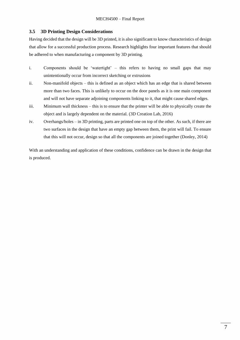
In this case, another function ‘Surface Primitives’ is used. During the scan, one cylindrical shape was
not fully picked up, due to it only being semi-circular on the scanning side. As can be seen in Figure 8,
this is easily rectified using the inbuilt functions in
the software. In other scenarios, the Polygon tool
may produce a shape that is simply incorrect or
inaccurate. Surface Primitives may also then be used
to create the correct shape manually and fit this to
the existing surface.
Using both of these tools together, individual segments can be formed as completed CAD files. They
now require assembly to form the completed door panel.
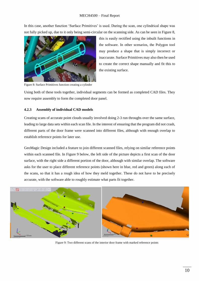
4.2.3 Assembly of individual CAD models
Creating scans of accurate point clouds usually involved doing 2-3 run throughs over the same surface,
leading to large data sets within each scan file. In the interest of ensuring that the program did not crash,
different parts of the door frame were scanned into different files, although with enough overlap to
establish reference points for later use.
GeoMagic Design included a feature to join different scanned files, relying on similar reference points
within each scanned file. In Figure 9 below, the left side of the picture depicts a first scan of the door
surface, with the right side a different portion of the door, although with similar overlap. The software
asks for the user to place different reference points (shown here in blue, red and green) along each of
the scans, so that it has a rough idea of how they meld together. These do not have to be precisely
accurate, with the software able to roughly estimate what parts fit together.
Figure 8: Surface Primitives function creating a cylinder
Figure 9: Two different scans of the interior door frame with marked reference points
MECH4500 – Final Report
11
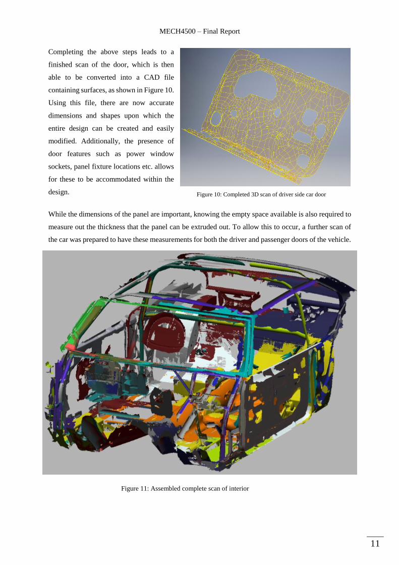
Completing the above steps leads to a
finished scan of the door, which is then
able to be converted into a CAD file
containing surfaces, as shown in Figure 10.
Using this file, there are now accurate
dimensions and shapes upon which the
entire design can be created and easily
modified. Additionally, the presence of
door features such as power window
sockets, panel fixture locations etc. allows
for these to be accommodated within the
design.
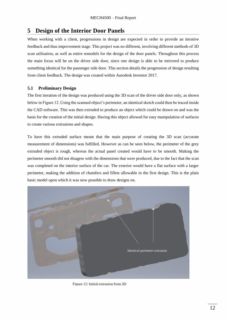
While the dimensions of the panel are important, knowing the empty space available is also required to
measure out the thickness that the panel can be extruded out. To allow this to occur, a further scan of
the car was prepared to have these measurements for both the driver and passenger doors of the vehicle.
Figure 10: Completed 3D scan of driver side car door
Figure 11: Assembled complete scan of interior
MECH4500 – Final Report
12
5 Design of the Interior Door Panels
When working with a client, progressions in design are expected in order to provide an iterative
feedback and thus improvement stage. This project was no different, involving different methods of 3D
scan utilisation, as well as entire remodels for the design of the door panels. Throughout this process
the main focus will be on the driver side door, since one design is able to be mirrored to produce
something identical for the passenger side door. This section details the progression of design resulting
from client feedback. The design was created within Autodesk Inventor 2017.
5.1 Preliminary Design
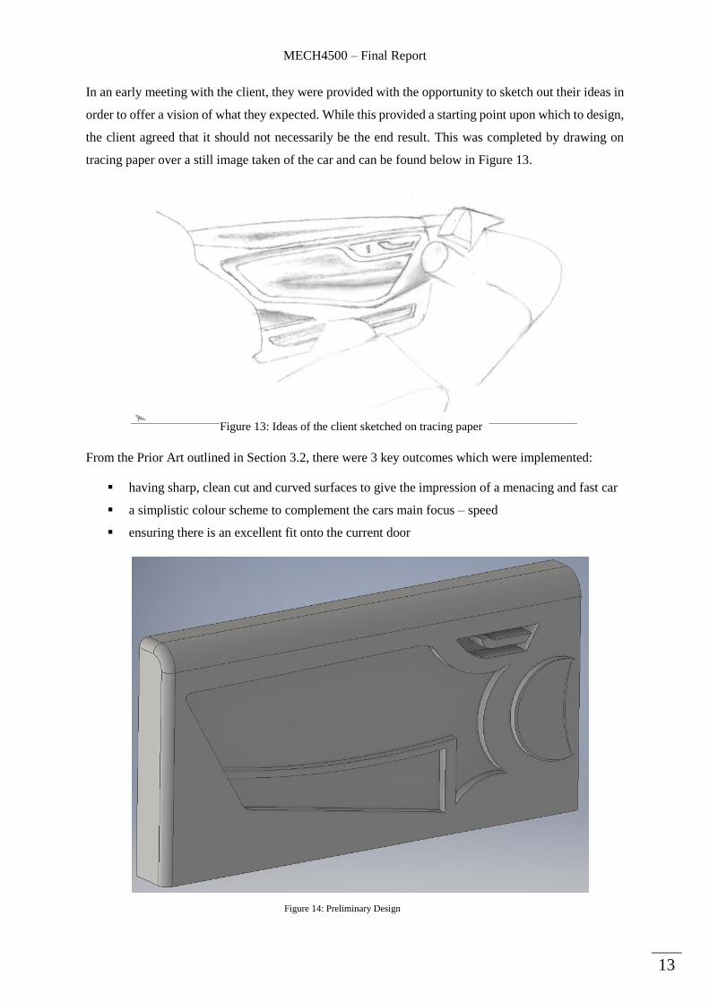
The first iteration of the design was produced using the 3D scan of the driver side door only, as shown
below in Figure 12. Using the scanned object’s perimeter, an identical sketch could then be traced inside
the CAD software. This was then extruded to produce an object which could be drawn on and was the
basis for the creation of the initial design. Having this object allowed for easy manipulation of surfaces
to create various extrusions and shapes.
To have this extruded surface meant that the main purpose of creating the 3D scan (accurate
measurement of dimensions) was fulfilled. However as can be seen below, the perimeter of the grey
extruded object is rough, whereas the actual panel created would have to be smooth. Making the
perimeter smooth did not disagree with the dimensions that were produced, due to the fact that the scan
was completed on the interior surface of the car. The exterior would have a flat surface with a larger
perimeter, making the addition of chamfers and fillets allowable in the first design. This is the plain
basic model upon which it was now possible to draw designs on.
Identical perimeter extrusion
Figure 12: Initial extrusion from 3D
Scan
MECH4500 – Final Report
13
In an early meeting with the client, they were provided with the opportunity to sketch out their ideas in
order to offer a vision of what they expected. While this provided a starting point upon which to design,
the client agreed that it should not necessarily be the end result. This was completed by drawing on
tracing paper over a still image taken of the car and can be found below in Figure 13.
From the Prior Art outlined in Section 3.2, there were 3 key outcomes which were implemented:
having sharp, clean cut and curved surfaces to give the impression of a menacing and fast car
a simplistic colour scheme to complement the cars main focus – speed
ensuring there is an excellent fit onto the current door
Figure 14: Preliminary Design
Figure 13: Ideas of the client sketched on tracing paper

MECH4500 – Final Report
14
Combining the ideas of the client with these focuses was not difficult as they overlapped quite
significantly. For example, the door lever drawn by the client was included in its entirety, as it had a
simplistic design with curved features that fit in with the overall theme of the design. Figure 14 shows
the preliminary design having the aforementioned features, with additional images available in
Appendix B.
There are parts of this design that are noticeably different to normal cars – for example the arm rest has
no holes for any placement of objects, something the client specifically wanted. Furthermore, there are
no speaker extrusions or any extra features, only a button for the window winding mechanism. In
general, there are no additional extras that add to the uniqueness of the panels – only the design itself.
5.1.1 Difficulties in Preliminary design
One reason for conducting a 3D scan was to have the entirety of the car able to be manipulated as
required in CAD, to allow for ease of design. Unfortunately, this feature was not available in the
produced final product, when the entire car was assembled – with there being two main issues.
Firstly, the produced file type was not conducive to the Inventor software being used, in that it only saw
the file as being one object, instead of many different parts assembled together. This meant that the
frame or window of the car could not be hidden, with a design only on the door panel being created
before being unhidden to see how they fit together. This meant that the width of the preliminary design
was not accurate and would have produced problems when attempting to fit on to the actual car.
The second problem stemmed from attempting to fix the first. Inventor has an inbuilt tool for situations
where the file is seen to be one whole surface, to break it down and allow the user the functionality
described above. However, due to the high quality of the 3D scan, this meant that the file produced was
much too large for this tool to function effectively, essentially making the assembled 3D file unusable
in the way that was desired. An additional solution was required to produce this functionality.
5.1.2 Client Feedback
Presentation of the preliminary design to the client resulted in the following general feedback:
the design was overly complicated and required more simplification, should move back to bare
minimums in terms of features and shapes (i.e. the semi-circle in the front)
needs more flow that come from curves – it should feel like an aerodynamic feature stretching
from the front to the back of the design
there was too much chamfer/fillet, needed to be readjusted
the lever was appropriate and would work as a mechanism to open the door
These were the basis of the design features that were adjusted in the next design.

MECH4500 – Final Report
15
5.2 Design Iteration Two
There were two main focuses going into the secondary design –figure out a new way to use the 3D scan
to overcome functionality issues outlined above, as well as to implement the design changes requested
by the client.
5.2.1 Complete 3D Model
In the preliminary design, only the driver side door panel scan was used to extrude an object upon which
the design was constructed. The downfall with this is not knowing the thickness that can be used for the
door itself and how it fits with the remainder of the car. To rectify this, a model was traced out for the
entire exterior shown in Figure 11, to produce a usable object as shown below.
The advantage of conducting this is that all objects apart from the door can be hidden. Using only the
visible door, a design can be created before the remaining parts are unhidden – being able to see how it
all fits together. In addition, this solves the problem of the required thickness as the maximum extent
that it could come out to was measured up until the start of the dash board.
5.2.2 Design
The new model provided a dimensionally accurate platform upon which the new design of the door
could be completed with the feedback provided from the client. The main focus of this design was to
give the door a feeling of flow that would be reflective of the outside menacing and fast look of the car.
From the prior art research conducted in Section 3.2.2, it was found that doors which were largely made
up of curved surfaces often looked the most like giving an impression of speed. As such, this design
was focused more on curvature in the doors features itself and is shown in Figure 16.
Figure 15: Model from created from 3D scan tracing
Door panel can be
easily drawn on
Driver door
thickness
present
MECH4500 – Final Report
16
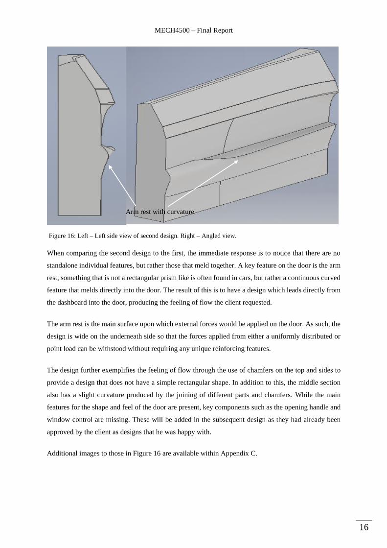
When comparing the second design to the first, the immediate response is to notice that there are no
standalone individual features, but rather those that meld together. A key feature on the door is the arm
rest, something that is not a rectangular prism like is often found in cars, but rather a continuous curved
feature that melds directly into the door. The result of this is to have a design which leads directly from
the dashboard into the door, producing the feeling of flow the client requested.
The arm rest is the main surface upon which external forces would be applied on the door. As such, the
design is wide on the underneath side so that the forces applied from either a uniformly distributed or
point load can be withstood without requiring any unique reinforcing features.
The design further exemplifies the feeling of flow through the use of chamfers on the top and sides to
provide a design that does not have a simple rectangular shape. In addition to this, the middle section
also has a slight curvature produced by the joining of different parts and chamfers. While the main
features for the shape and feel of the door are present, key components such as the opening handle and
window control are missing. These will be added in the subsequent design as they had already been
approved by the client as designs that he was happy with.
Additional images to those in Figure 16 are available within Appendix C.
Figure 16: Left – Left side view of second design. Right – Angled view.
Arm rest with curvature
MECH4500 – Final Report
17
5.2.3 Design Creation
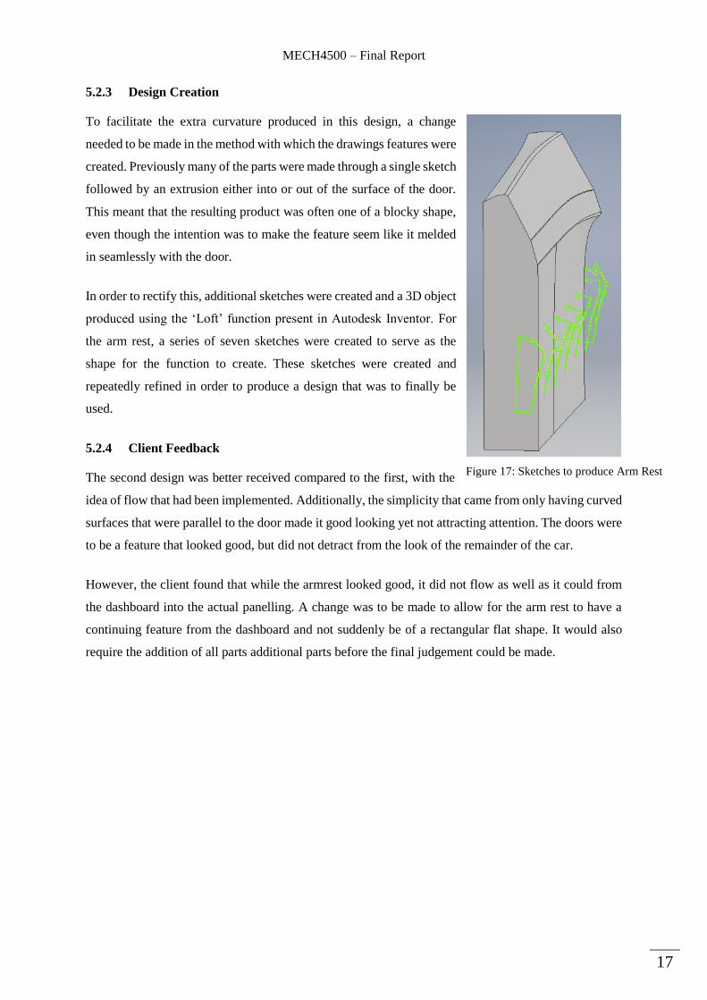
To facilitate the extra curvature produced in this design, a change
needed to be made in the method with which the drawings features were
created. Previously many of the parts were made through a single sketch
followed by an extrusion either into or out of the surface of the door.
This meant that the resulting product was often one of a blocky shape,
even though the intention was to make the feature seem like it melded
in seamlessly with the door.
In order to rectify this, additional sketches were created and a 3D object
produced using the ‘Loft’ function present in Autodesk Inventor. For
the arm rest, a series of seven sketches were created to serve as the
shape for the function to create. These sketches were created and
repeatedly refined in order to produce a design that was to finally be
used.
5.2.4 Client Feedback
The second design was better received compared to the first, with the
idea of flow that had been implemented. Additionally, the simplicity that came from only having curved
surfaces that were parallel to the door made it good looking yet not attracting attention. The doors were
to be a feature that looked good, but did not detract from the look of the remainder of the car.
However, the client found that while the armrest looked good, it did not flow as well as it could from
the dashboard into the actual panelling. A change was to be made to allow for the arm rest to have a
continuing feature from the dashboard and not suddenly be of a rectangular flat shape. It would also
require the addition of all parts additional parts before the final judgement could be made.
Figure 17: Sketches to produce Arm Rest
MECH4500 – Final Report
18
5.3 Final Design Features
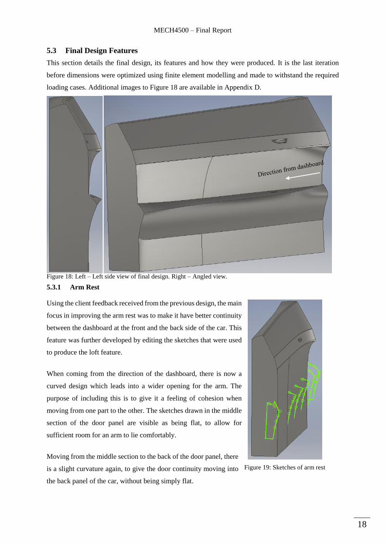
This section details the final design, its features and how they were produced. It is the last iteration
before dimensions were optimized using finite element modelling and made to withstand the required
loading cases. Additional images to Figure 18 are available in Appendix D.
5.3.1 Arm Rest
Using the client feedback received from the previous design, the main
focus in improving the arm rest was to make it have better continuity
between the dashboard at the front and the back side of the car. This
feature was further developed by editing the sketches that were used
to produce the loft feature.
When coming from the direction of the dashboard, there is now a
curved design which leads into a wider opening for the arm. The
purpose of including this is to give it a feeling of cohesion when
moving from one part to the other. The sketches drawn in the middle
section of the door panel are visible as being flat, to allow for
sufficient room for an arm to lie comfortably.
Moving from the middle section to the back of the door panel, there
is a slight curvature again, to give the door continuity moving into
the back panel of the car, without being simply flat.
Figure 18: Left – Left side view of final design. Right – Angled view.
Figure 19: Sketches of arm rest
MECH4500 – Final Report
19
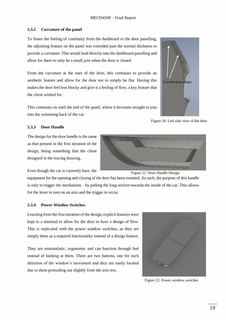
5.3.2 Curvature of the panel
To foster the feeling of continuity from the dashboard to the door panelling,
the adjoining feature on the panel was extended past the normal thickness to
provide a curvature. This would lead directly into the dashboard panelling and
allow for there to only be a small join when the door is closed.
From the curvature at the start of the door, this continues to provide an
aesthetic feature and allow for the door not to simply be flat. Having this
makes the door feel less blocky and give it a feeling of flow, a key feature that
the client wished for.
This continues on until the end of the panel, where it becomes straight to join
into the remaining back of the car.
5.3.3 Door Handle
The design for the door handle is the same
as that present in the first iteration of the
design, being something that the client
designed in the tracing drawing.
Even though the car is currently bare, the
equipment for the opening and closing of the door has been retained. As such, the purpose of this handle
is only to trigger the mechanism – by pulling the long section towards the inside of the car. This allows
for the lever to turn on an axis and the trigger to occur.
5.3.4 Power Window Switches
Learning from the first iteration of the design, explicit features were
kept to a minimal to allow for the door to have a design of flow.
This is replicated with the power window switches, as they are
simply there as a required functionality instead of a design feature.
They are minimalistic, ergonomic and can function through feel
instead of looking at them. There are two buttons, one for each
direction of the window’s movement and they are easily located
due to them protruding out slightly from the arm rest.
Figure 21: Door Handle Design
Figure 22: Power window switches
Curved door shape
Figure 20: Left side view of the door

MECH4500 – Final Report
20
5.3.5 Fillets and Other Features
To further contribute to the feeling of flow and aerodynamics, the outside of the door panel had fillets
applied to it so that the edges did not remain flat and give it a blocky shape. In addition to this, a centre
panel was added purely for aesthetic reasons and to further enhance the appeal described above.
The final design is the culmination of research through prior art, client feedback and unique, new input.
Features such as the centre panel shown above stem from the prior art conclusions, whereby clean cut
curved surfaces lead to an appearance of flow, a reflection of the car’s speed. The simplistic shape and
edges add to the menacing look the client wished for to give the Camaro a futuristic feel in an old car.
5.3.6 Exclusions
It is noticeable that the door panel designed does not have certain features that everyday cars would
have included in them. This is mainly due to the client wishing for the car to be a model car more than
a functional daily driver. As such, this means that features such as the following were excluded:
Speaker holes
Handle to pull the door closed
Pockets in arm rest to place objects in
Pocket below arm rest for larger objects
Internal locking mechanism
Motorized door mirror adjustment
Furthermore, technical drawings are not included within this report due to the final output file being of
CAD format, meaning dimensions are included. Lastly, since this design is going to be a one-off
production, optimization has not been made in consideration of reduction in material usage or cost, but
only focusing on the design.
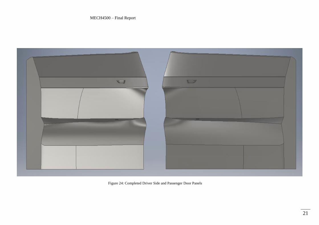
5.4 Trim and Colour Scheme
The client has not yet decided on the exterior trim on the door panelling, meaning that this is not able
to yet be modelled. However, the express wish that the inside of the car look like the outside suggests
that the interior would also be of a dark colour – likely black. This was the assumption used to colour
the panelling and apply it to the models shown below.
Fillets applied
Centre Panel
Figure 23: Additional aesthetic features
MECH4500 – Final Report
21
Figure 24: Completed Driver Side and Passenger Door Panels
MECH4500 – Final Report
22
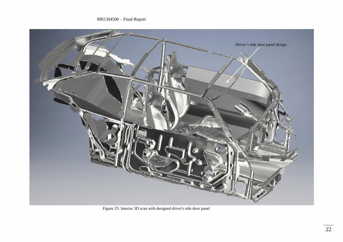
Figure 25: Interior 3D scan with designed driver's side door panel
Driver’s side door panel design
MECH4500 – Final Report
23
6 Finite Element Modelling (FEM)
With a completed design, the next stage in the project was to test to see if it was able to withstand the
forces it would experience. In this section is the detail of each step that was conducted in the process of
FEM testing, including the selection of materials, constraints, loads and meshing. The client has also
mentioned that the vehicle will not be roadworthy and only be a model car, meaning that Australian
design standards are not considered within this testing section. The analysis was completed in Autodesk
Inventor.
6.1 Material Selection
Within Section 3.4 is a comparison of the two materials highlighted by the client as being options –
carbon fibre and fiberglass. Fibreglass is chosen as the material to be used, as it is a cheaper option with
the same strength as carbon fibre. Additionally, it is easier to paint and is easily printed with a generic
3D printer allowing for more flexibility with the design stage.
As the material was not present within the available Autodesk Inventor library, it was manually added
with relevant material properties that can be found in Appendix E.
6.2 Attachment method
There were two main options to attach the panel to the door itself, either through the use of bolts or an
adhesive. In the past experience of the client, bolts were found to make the door less aesthetically
pleasing and made the installation and removal of the door more difficult than necessary. It was the
preference of the client to find an adhesive or glue to attach the door panels.
While there are many choices available on the market, this section will use a popular option called
‘Gorilla Glue’ which has been specifically designed as an extremely strong adhesive meant for similar
purposes. This adhesive is also easily applied to many different materials, with properties that are
similar to fibreglass (GorillaGlue, 2016).
For the purpose of FEM analysis, the glue will be assumed to be applied around the perimeter, on the
back of the interior door panel, before being secured to the frame of the door. To model this within
FEM software, the back panel was made flat and was fixed using the available option. This means that
the entirety of the panel has a fixed constraint that will take the load applied.
MECH4500 – Final Report
24
6.3 Loading Cases
There are only two situations in which the door is used in the car – firstly to enter or exit the vehicle
and the other is when inside the vehicle to use as an armrest. To replicate these situations, a point load
and a uniformly distributed load are placed upon the door panel for testing. Within the software and
stress testing diagrams, a safety factor of 1.5 has been included.
For the purpose of any testing within this section, a body weight of 120kg is used as this is sufficiently
above that of the clients and greater than the average body weight of 74.1kg (Walpole, 2011).
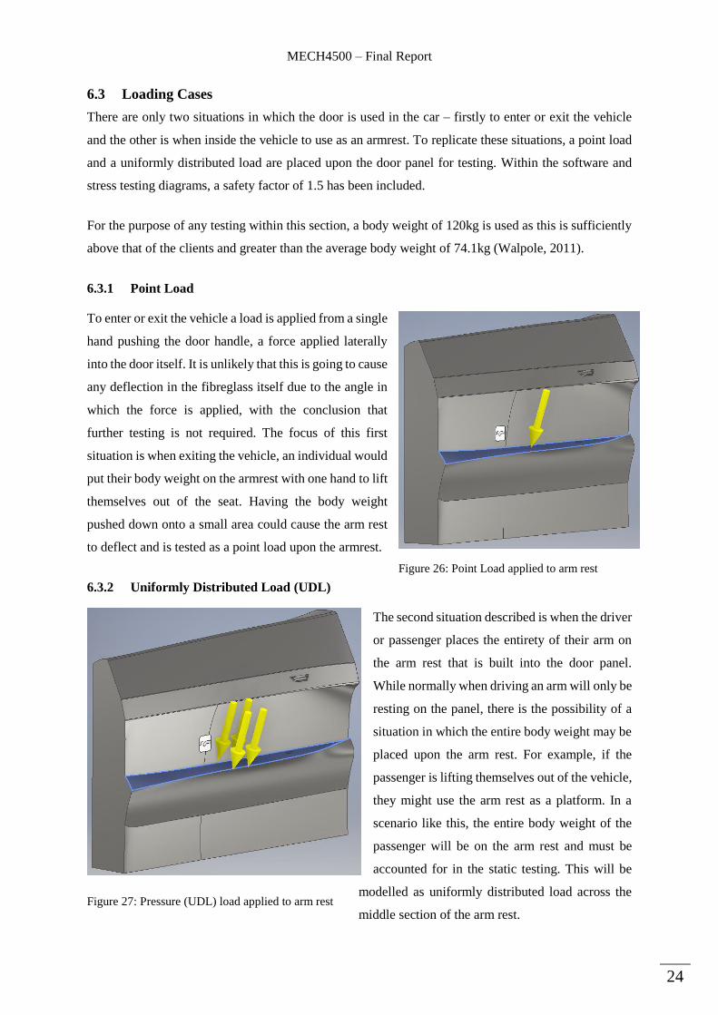
6.3.1 Point Load
To enter or exit the vehicle a load is applied from a single
hand pushing the door handle, a force applied laterally
into the door itself. It is unlikely that this is going to cause
any deflection in the fibreglass itself due to the angle in
which the force is applied, with the conclusion that
further testing is not required. The focus of this first
situation is when exiting the vehicle, an individual would
put their body weight on the armrest with one hand to lift
themselves out of the seat. Having the body weight
pushed down onto a small area could cause the arm rest
to deflect and is tested as a point load upon the armrest.
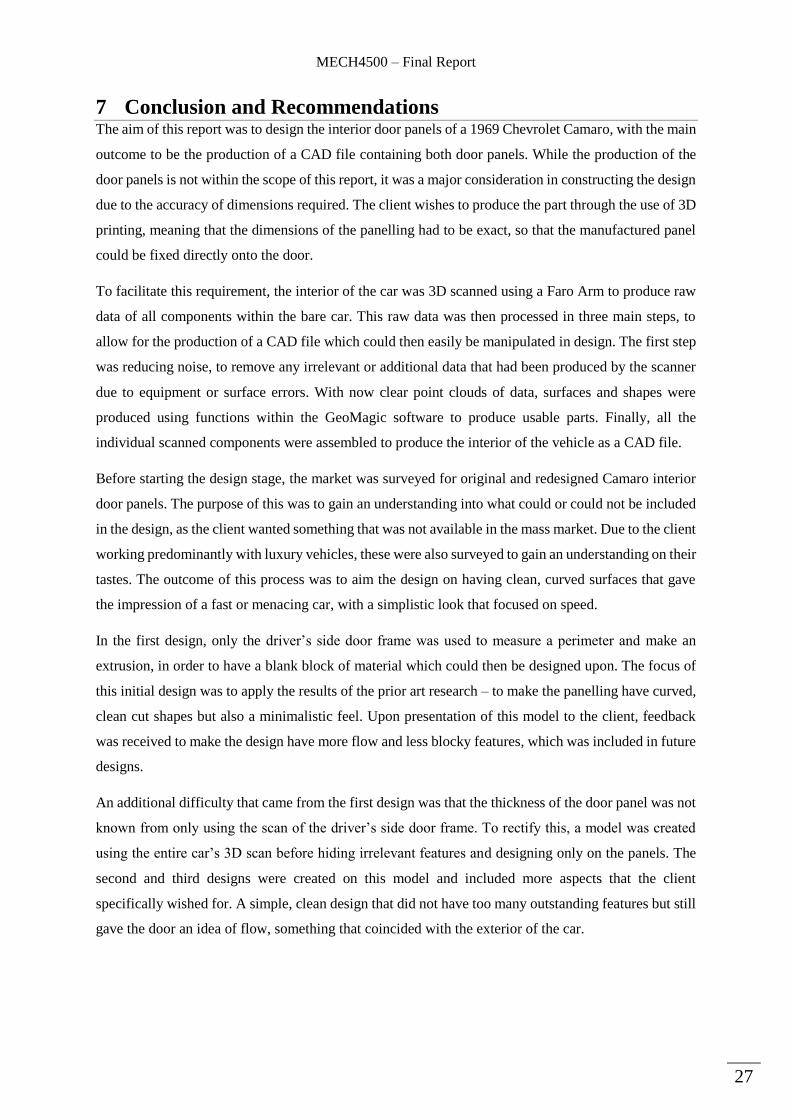
6.3.2 Uniformly Distributed Load (UDL)
The second situation described is when the driver
or passenger places the entirety of their arm on
the arm rest that is built into the door panel.
While normally when driving an arm will only be
resting on the panel, there is the possibility of a
situation in which the entire body weight may be
placed upon the arm rest. For example, if the
passenger is lifting themselves out of the vehicle,
they might use the arm rest as a platform. In a
scenario like this, the entire body weight of the
passenger will be on the arm rest and must be
accounted for in the static testing. This will be
modelled as uniformly distributed load across the
middle section of the arm rest.
Figure 26: Point Load applied to arm rest
Figure 27: Pressure (UDL) load applied to arm rest

MECH4500 – Final Report
25
6.4 Meshing
Due to the simplicity of the vast majority of the shape, the meshing was not required to be extremely
fine except in more important parts such as the arm rest. However, to ensure that the arm rest was being
correctly analysed an iterative computational technique present within the Inventor software was used.
As the mesh becomes more fine, the results of any stress analysis tends to vary – leading to results that
cannot be relied upon. To overcome this, the iterative technique modifies the mesh, completes the
simulation again and compares the result to previous results with different meshes (Autodesk, 2014).
Having many iterations allows for stress results to reach a point of convergence, which is then used as
the final value of impact from the applied force or pressure. An example of the mesh used is shown
below, with the arm rest, door lever and window buttons having a finer mesh.
Figure 28: Meshing of the door panel

MECH4500 – Final Report
26
6.5 Simulation Results
Using the described scenarios above, the simulation was run to calculate the effect both the loading
cases would have on the door panel. Displayed below are the results from the iterative computational
method to produce a converged stress analysis diagram.
It is worth noting that the arrow pointed at the arm rest is not the only location that the point load is
applied. To find the location of maximum stress concentration, the point load was applied incrementally
across the surface of the arm rest and through the iterative process described above, the highest stress
concentrations were found. The convergence of all the forces results are shown in the diagram above.
The diagrams above show that as expected, the majority of the force is distributed across the length of
the arm rest. When looking at the diagram on the right with the UDL applied, the point of maximum
force (red) is located at the widest part of the arm rest. With the maximum force applied, the arm rest
only deflects marginally and does not fracture as it is well under the material limits of fiberglass.
Furthermore, due to the way the lofts were drawn in the sketching, the widest part of the arm rest is also
the thickest underneath with the most material present, allowing it to be able to withstand greater force.
When applying point loads across the arm rest, there is a much larger dispersion of forces that occur
but with a maximum force value that is less than that of the UDL. While the forces might be more
widespread, there is less deflection present in the diagram due to it having a point load applied. The
extra thickness present under the arm rest in the design has led for the door to be able to withstand both
the loading cases that were outlined and tested. The simulation also calculated values for the stresses
that would be applied to the arm rest, but are extremely small values and thus considered insignificant.
From the results of this testing, the design is considered to be successful in being able to withstand the
loading cases applied to them. As such, no further iterations are required and the design is complete.
Figure 29: Left - Point Load Analysis, Right - UDL Analysis
MECH4500 – Final Report
27
7 Conclusion and Recommendations The aim of this report was to design the interior door panels of a 1969 Chevrolet Camaro, with the main
outcome to be the production of a CAD file containing both door panels. While the production of the
door panels is not within the scope of this report, it was a major consideration in constructing the design
due to the accuracy of dimensions required. The client wishes to produce the part through the use of 3D
printing, meaning that the dimensions of the panelling had to be exact, so that the manufactured panel
could be fixed directly onto the door.
To facilitate this requirement, the interior of the car was 3D scanned using a Faro Arm to produce raw
data of all components within the bare car. This raw data was then processed in three main steps, to
allow for the production of a CAD file which could then easily be manipulated in design. The first step
was reducing noise, to remove any irrelevant or additional data that had been produced by the scanner
due to equipment or surface errors. With now clear point clouds of data, surfaces and shapes were
produced using functions within the GeoMagic software to produce usable parts. Finally, all the
individual scanned components were assembled to produce the interior of the vehicle as a CAD file.
Before starting the design stage, the market was surveyed for original and redesigned Camaro interior
door panels. The purpose of this was to gain an understanding into what could or could not be included
in the design, as the client wanted something that was not available in the mass market. Due to the client
working predominantly with luxury vehicles, these were also surveyed to gain an understanding on their
tastes. The outcome of this process was to aim the design on having clean, curved surfaces that gave
the impression of a fast or menacing car, with a simplistic look that focused on speed.
In the first design, only the driver’s side door frame was used to measure a perimeter and make an
extrusion, in order to have a blank block of material which could then be designed upon. The focus of
this initial design was to apply the results of the prior art research – to make the panelling have curved,
clean cut shapes but also a minimalistic feel. Upon presentation of this model to the client, feedback
was received to make the design have more flow and less blocky features, which was included in future
designs.
An additional difficulty that came from the first design was that the thickness of the door panel was not
known from only using the scan of the driver’s side door frame. To rectify this, a model was created
using the entire car’s 3D scan before hiding irrelevant features and designing only on the panels. The
second and third designs were created on this model and included more aspects that the client
specifically wished for. A simple, clean design that did not have too many outstanding features but still
gave the door an idea of flow, something that coincided with the exterior of the car.
MECH4500 – Final Report
28
The final design chosen was the third iteration, which included only the most basic requirements of
features as was requested by the client. Necessities in a panel included a door lever to open and close
the door, as well as two window buttons to control each direction of window operation. The main feature
in the design was the arm rest, which was required for comfort in driving, but also added a feeling of
flow across the entirety of the door panelling.
With a final design, static load testing was then conducted to ensure that the design could withstand the
forces that might be applied. A material was first chosen in consultation with the client who narrowed
the search to two options – carbon fibre or fiberglass. From research conducted, fiberglass was seen to
be the more reasonable of the two options as it had the same strength as carbon fibre, but was cheaper
to obtain and produce. Fiberglass also offered the ability to add a trim and colouring more easily.
Static load testing also requires the fixture of the object in question, leading to an attachment method
solution to be found for the door panelling. In their past experience, the client had found that attachment
through bolts was not aesthetically pleasing and preferred to use industrial strength glue. Gorilla Glue
was identified as being an option the client could use and would be applied to the perimeter at the back
of the panel. This was replicated within the testing software, having the entire back panel fixed.
There were two loading cases identified for static testing, a point load and a uniformly distributed load.
Both were found to be most likely applied to the arm rest present on the door panel, as the driver or
passenger enters or exists the vehicle. A mass of 120kg was used as the point load and also distributed
across the arm rest as a pressure for the scenarios, with a 1.5 safety factor also incorporated. An iterative
method was used when creating meshing, using different levels of refinement to produce stress values
that would eventually converge to produce an accurate result.
The results of the testing showed that the areas of greatest stress were located around the centre of the
arm result, where the loads would most heavily be applied. However, this was anticipated in the design
stage with the middle section being made the widest to compensate for the load. Values of stress
produced from the simulation were of orders of magnitude that were extremely small and thus were
found to be insignificant. The outcome of the stress analysis was to say that the door panels could
withstand the two loading cases that were tested.
An interior design has been completed for both the driver side and passenger doors, passing the required
static loading tests. Using the produced CAD file, the client is now able to manufacture the door panel
using a 3D printer – fulfilling their requirement. However, due to time and resource limitations, not all
factors were able to be conducted within this report. Recommendations on further work to be completed
before production can be found below.
MECH4500 – Final Report
29
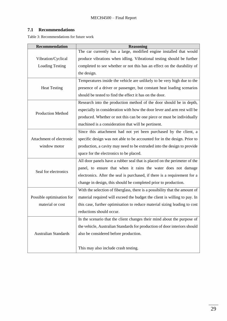
7.1 Recommendations
Table 3: Recommendations for future work
Recommendation Reasoning
Vibration/Cyclical
Loading Testing
The car currently has a large, modified engine installed that would
produce vibrations when idling. Vibrational testing should be further
completed to see whether or not this has an effect on the durability of
the design.
Heat Testing
Temperatures inside the vehicle are unlikely to be very high due to the
presence of a driver or passenger, but constant heat loading scenarios
should be tested to find the effect it has on the door.
Production Method
Research into the production method of the door should be in depth,
especially in consideration with how the door lever and arm rest will be
produced. Whether or not this can be one piece or must be individually
machined is a consideration that will be pertinent.
Attachment of electronic
window motor
Since this attachment had not yet been purchased by the client, a
specific design was not able to be accounted for in the design. Prior to
production, a cavity may need to be extruded into the design to provide
space for the electronics to be placed.
Seal for electronics
All door panels have a rubber seal that is placed on the perimeter of the
panel, to ensure that when it rains the water does not damage
electronics. After the seal is purchased, if there is a requirement for a
change in design, this should be completed prior to production.
Possible optimisation for
material or cost
With the selection of fiberglass, there is a possibility that the amount of
material required will exceed the budget the client is willing to pay. In
this case, further optimisation to reduce material sizing leading to cost
reductions should occur.
Australian Standards
In the scenario that the client changes their mind about the purpose of
the vehicle, Australian Standards for production of door interiors should
also be considered before production.
This may also include crash testing.
MECH4500 – Final Report
30
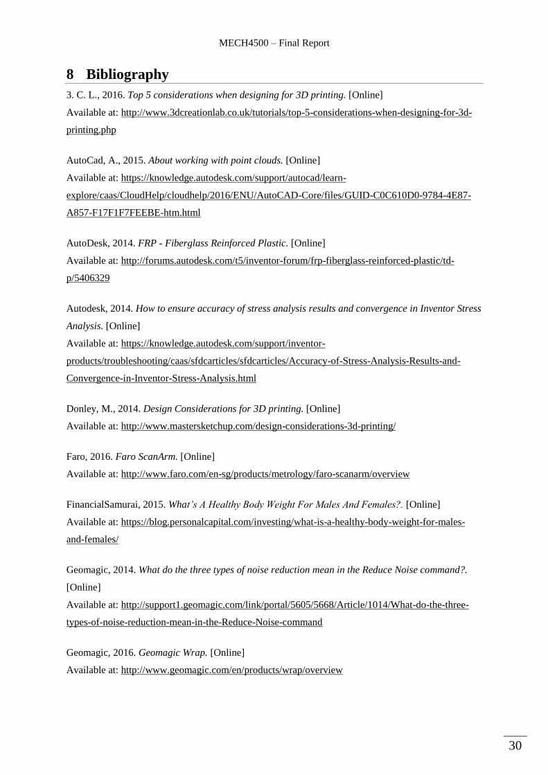
8 Bibliography
3. C. L., 2016. Top 5 considerations when designing for 3D printing. [Online]
Available at: http://www.3dcreationlab.co.uk/tutorials/top-5-considerations-when-designing-for-3d-
printing.php
AutoCad, A., 2015. About working with point clouds. [Online]
Available at: https://knowledge.autodesk.com/support/autocad/learn-
explore/caas/CloudHelp/cloudhelp/2016/ENU/AutoCAD-Core/files/GUID-C0C610D0-9784-4E87-
A857-F17F1F7FEEBE-htm.html
AutoDesk, 2014. FRP - Fiberglass Reinforced Plastic. [Online]
Available at: http://forums.autodesk.com/t5/inventor-forum/frp-fiberglass-reinforced-plastic/td-
p/5406329
Autodesk, 2014. How to ensure accuracy of stress analysis results and convergence in Inventor Stress
Analysis. [Online]
Available at: https://knowledge.autodesk.com/support/inventor-
products/troubleshooting/caas/sfdcarticles/sfdcarticles/Accuracy-of-Stress-Analysis-Results-and-
Convergence-in-Inventor-Stress-Analysis.html
Donley, M., 2014. Design Considerations for 3D printing. [Online]
Available at: http://www.mastersketchup.com/design-considerations-3d-printing/
Faro, 2016. Faro ScanArm. [Online]
Available at: http://www.faro.com/en-sg/products/metrology/faro-scanarm/overview
FinancialSamurai, 2015. What’s A Healthy Body Weight For Males And Females?. [Online]
Available at: https://blog.personalcapital.com/investing/what-is-a-healthy-body-weight-for-males-
and-females/
Geomagic, 2014. What do the three types of noise reduction mean in the Reduce Noise command?.
[Online]
Available at: http://support1.geomagic.com/link/portal/5605/5668/Article/1014/What-do-the-three-
types-of-noise-reduction-mean-in-the-Reduce-Noise-command
Geomagic, 2016. Geomagic Wrap. [Online]
Available at: http://www.geomagic.com/en/products/wrap/overview
MECH4500 – Final Report
31
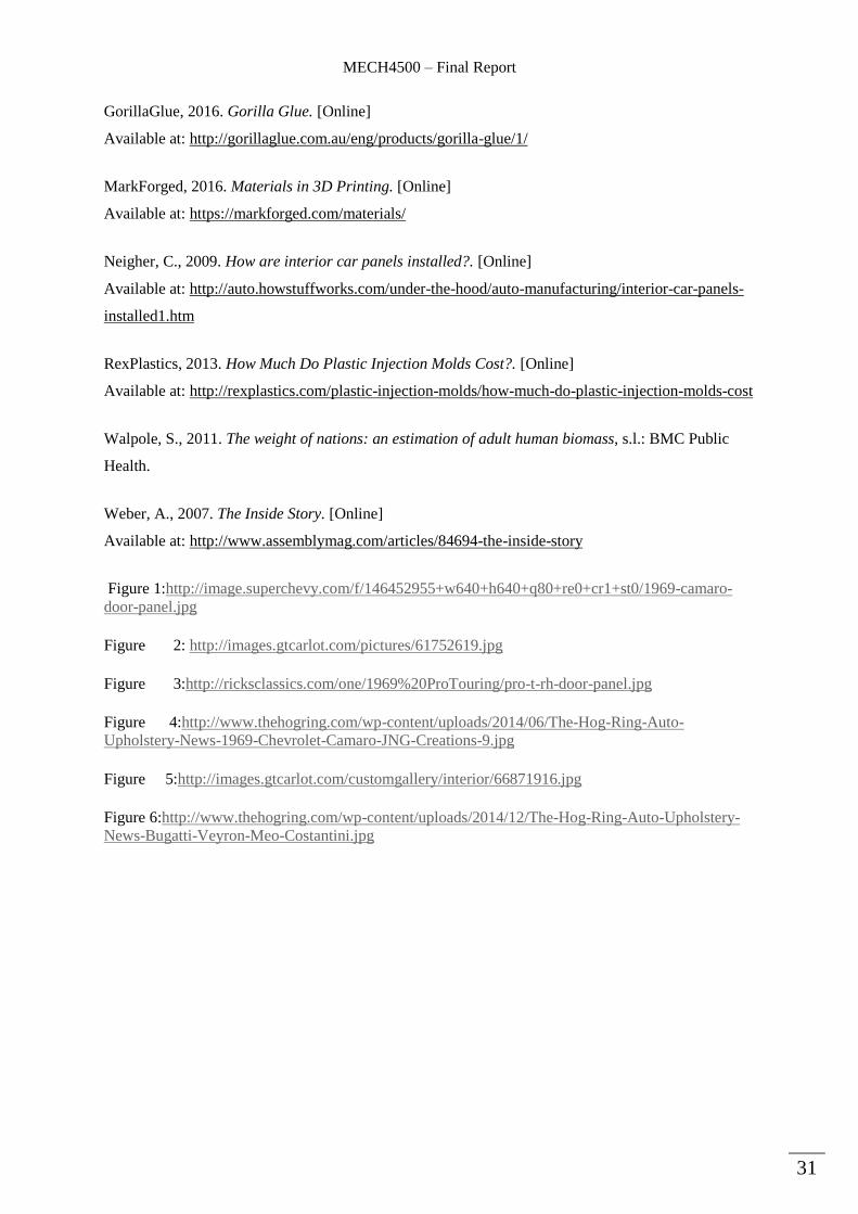
GorillaGlue, 2016. Gorilla Glue. [Online]
Available at: http://gorillaglue.com.au/eng/products/gorilla-glue/1/
MarkForged, 2016. Materials in 3D Printing. [Online]
Available at: https://markforged.com/materials/
Neigher, C., 2009. How are interior car panels installed?. [Online]
Available at: http://auto.howstuffworks.com/under-the-hood/auto-manufacturing/interior-car-panels-
installed1.htm
RexPlastics, 2013. How Much Do Plastic Injection Molds Cost?. [Online]
Available at: http://rexplastics.com/plastic-injection-molds/how-much-do-plastic-injection-molds-cost
Walpole, S., 2011. The weight of nations: an estimation of adult human biomass, s.l.: BMC Public
Health.
Weber, A., 2007. The Inside Story. [Online]
Available at: http://www.assemblymag.com/articles/84694-the-inside-story
Figure 1:http://image.superchevy.com/f/146452955+w640+h640+q80+re0+cr1+st0/1969-camaro-
door-panel.jpg
Figure 2: http://images.gtcarlot.com/pictures/61752619.jpg
Figure 3:http://ricksclassics.com/one/1969%20ProTouring/pro-t-rh-door-panel.jpg
Figure 4:http://www.thehogring.com/wp-content/uploads/2014/06/The-Hog-Ring-Auto-
Upholstery-News-1969-Chevrolet-Camaro-JNG-Creations-9.jpg
Figure 5:http://images.gtcarlot.com/customgallery/interior/66871916.jpg
Figure 6:http://www.thehogring.com/wp-content/uploads/2014/12/The-Hog-Ring-Auto-Upholstery-
News-Bugatti-Veyron-Meo-Costantini.jpg
MECH4500 – Final Report
32
9 Appendices
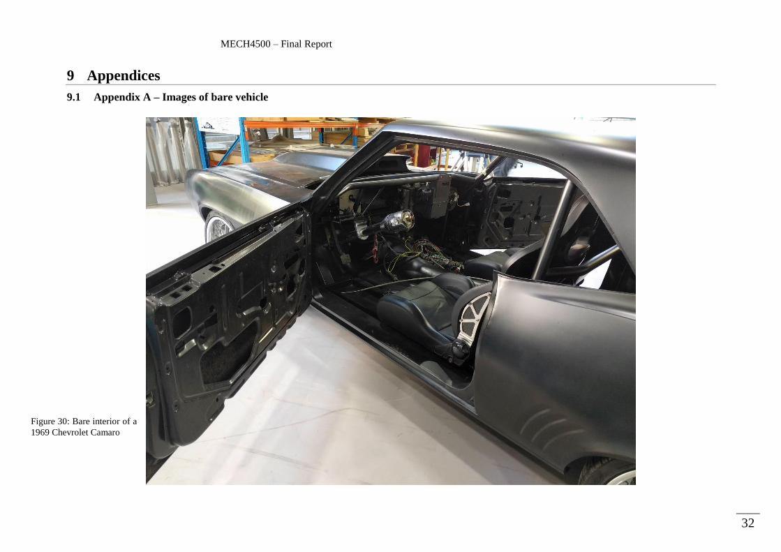
9.1 Appendix A – Images of bare vehicle
Figure 30: Bare interior of a
1969 Chevrolet Camaro

MECH4500 – Final Report
33
9.2 Appendix B – Preliminary Design screenshots
Figure 31: Initial design left side drivers side view
Figure 32: Rendered front on view
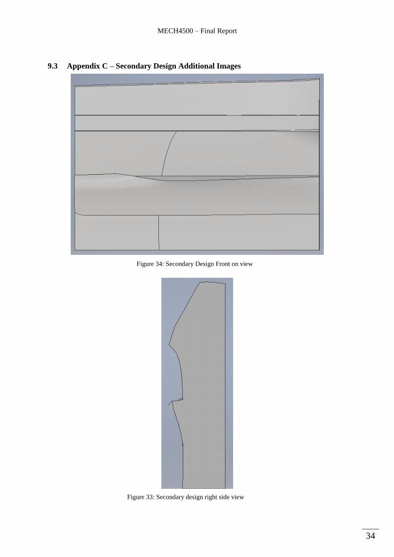
MECH4500 – Final Report
34
9.3 Appendix C – Secondary Design Additional Images
Figure 34: Secondary Design Front on view
Figure 33: Secondary design right side view
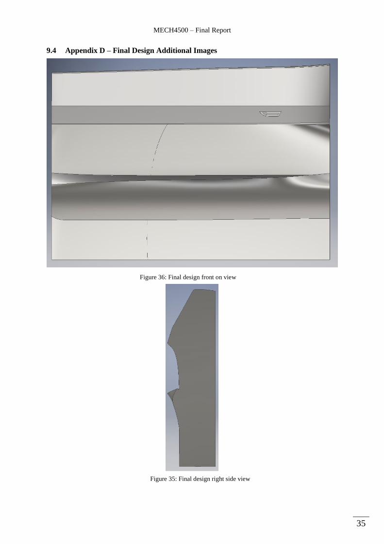
MECH4500 – Final Report
35
9.4 Appendix D – Final Design Additional Images
Figure 36: Final design front on view
Figure 35: Final design right side view

MECH4500 – Final Report
36
9.5 Appendix E - Fiberglass Material Properties
Characteristic Value
Thermal Conductivity 6.687 x10⁻² btu/(in/sec/Fahrenheit)
Specific Heat 0.3 btu/(lb-Fahrenheit)
Thermal Expansion Coefficient 1.3 x10⁻⁵ inv Fahrenheit
Behaviour Isotropic
Young’s Modulus 8x10⁵ psi
Poisson’s Ratio 0.40
Shear Modulus 2.741 x10⁵ psi
Density 0.065 pound per cubic inch
Yield Strength 1 x10⁴ psi
Tensile Strength 1 x10⁴ psi
(AutoDesk, 2014)