Embed Size (px)
Citation preview
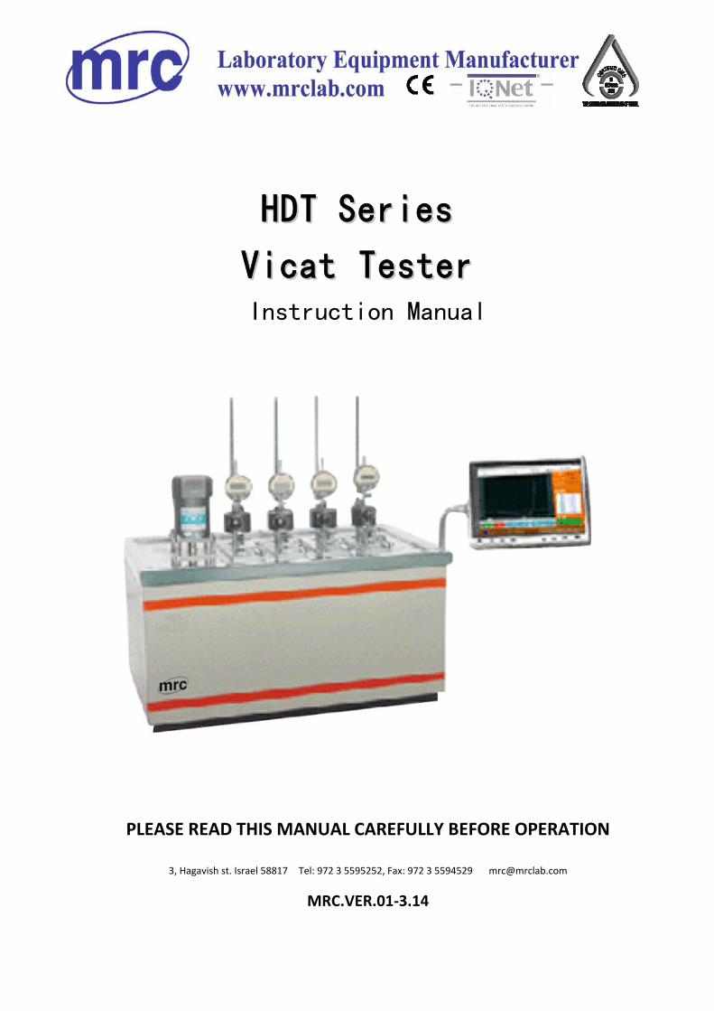
HHDDTT SSeerriieess
VViiccaatt TTeesstteerr Instruction Manual
PLEASE READ THIS MANUAL CAREFULLY BEFORE OPERATION
3, Hagavish st. Israel 58817 Tel: 972 3 5595252, Fax: 972 3 5594529 [email protected]
MRC.VER.01-3.14

HDT/Vicat Tester Operating Manual
1
Content
Section 1-- Introduction................................................................................................................ 4
1.1 Function.......................................................................................................................4
1.2 Standards ....................................................................................................................4
1.3 Technical parameters ..................................................................................................4
1.4 Principle .......................................................................................................................5
1.5 Working Condition .......................................................................................................6
1.6 Electrical requirement ..................................................................................................6
1.7 Dimension:...................................................................................................................6
Section 2—Installation ................................................................................................................. 7
2.1 Unpacking and inspection............................................................................................7
2.2 Installation of hardware................................................................................................7
Section 3—Component................................................................................................................ 9
3.1 Main frame...................................................................................................................9
3.2 Accessory ..................................................................................................................11
Section 4-Opearation procedures .............................................................................................. 12
4.2 specimen preparation and installation .......................................................................22
4.3 Weights and deflection settings .................................................................................23
4.2.5 Temperature switch ................................................................................................27
4.3 Parameter setting interface........................................................................................27
4.4 Start a new test..........................................................................................................30
4.5 Test result view .......................................................................................................31
4.6 Storage device...........................................................................................................32
5 Calibration ............................................................................................................................ 32
5.1 Temperature calibration.............................................................................................32
5.2 Deflection calibration .................................................................................................33
6 Trouble shootings............................................................................................................... 34
7 Maintenance....................................................................................................................... 35

HDT/Vicat Tester Operating Manual 2
IMPORTANT SAFETY INSTRUCTIONS
Read of these instructions carefully before operating the instrument
1. Save these instructions for future reference.
2. Do not use this instrument in combustible and explosive surroundings, take care
of the ventilation.
3. When the instrument is powered on, do not touch the parts inside and remove the
wires.
4. When do the following operations must be directed by the expert: transport,
installation, connection, operation, servicing .
5. Only operate the instrument from the type of power source indicated on the label.
6. Do not attempt to service this product yourself. Opening or removing covers may
expose you to dangerous high voltages.
7. Do not allow anything to rest on the power cord. Do not locate this product where
persons will walk on the cord.
8. There is no creepage protect device in this instrument, so a breaker must be
installed in the power port (The power must be no less than 4.5kW).
9. When a trouble is occurring, turn off the power supply at once.
10. The power supply should be single-phase, three wire. Do not use this instrument
if the power wire or the plug is damaged.
11. Do not touch the instrument surface when operating.
12. The medium must be pure without any impurity.
13. Ventilating device is needed when use this instrument to test.
14. Do not heat this instrument before adding the heating medium.
15. Please do not leave when doing a test with this instrument.
16. When do the HDT test, if the test temperature is high and approach to the
burning point of the heating medium, do not raise the test station at once after
testing, or the metal friction will produce sparkle, then result in fire.
HDT/Vicat Tester Operating Manual
3
17. If an extension cord is used with this product, make sure that the total ampere
ratings of the product(s) plugged into the extension cord do not exceed the
extension cord ampere rating.
18. Refer all servicing to MRC Co.,Ltd’ Technical Support Staff:
MRC CO.,LTD
HGAVISH 3, HOLON, ISRAEL
Phone: +972-3-5595252
Fax: +972-3-5594529
E-mail: [email protected]
19. Visit us on the web: http://www.mrclab.com
HDT/Vicat Tester Operating Manual 4
Section 1-- Introduction
1.1 Function
HDT series table type HDT/Vicat testers are mainly used to do the HDT test and
Vicat test for non-metal materials: such as plastic, rubber, nylon and electrical
insulating material. They are the perfect test tools for chemical industry, R&D
department and academies or colleges. The operator must read this document
carefully before commencing any activities on the instrument.
1.2 Standards
the tester conforms to the following standards:
GB/T 1633-2000 Plastics--Thermoplastic materials--Determination of Vicat
sofening temperature (VST)
GB/T 1634-2004 Test method of heat deflection temperature underbending load
for plastics
ISO75-1 Plastics — Determination of temperature of deflection under load —
Part 1: General test method
ISO-2 Plastics — Determination of temperature of deflection under load — Part
2: Plastics and ebonite
ISO 36 Plastics — Thermoplastic materials— Determination of Vicat softening temperature (VST)
Also, it conforms to other equivalent standards.
1.3 Technical parameters
1. Temp. rising range: Room temp.~300OC
2. Constant Temp. control range: 50~300 OC
3. Temp. rate: ( 120±10 ) OC/h [(12.0±1.0) OC/6min]
( 50±5 ) OC/h [(5.0±0.5) OC/6min]
or 50~120 OC/h random setting

HDT/Vicat Tester Operating Manual
5
4. Temp. Display error (Max.): ±0.5 OC
5. Deflection display error (Max.): ±0.005mm
6. Deflection measure range: -0.2mm ~ 10mm
7. Test station: 1-6
8. Number of temperature sensors:
111 Series: one sensor for each test station
110 Series: one sensor only
9. Weight of loading rod and load-carrying plate: 60g
10. Heat medium: Silicone oil or transformer oil (The recommended viscosity of
Silicon oil is 100Cst~200Cst, and its flash point should higher than 300OC; the
transformer oil should reach 240OC.)
10. Cooling mode: Natural cooling 150�above,Natural cooling or water cooling
150OC below
11. Heating power: 4kW for 1 or 2 stations
5.5kW for 3 or 4 stations
6kW for 5 or 6 stations
12. Power consumption: 5kW for 1 or 2 stations
6.5kW for 3 or 4 stations
7kW for 5 or 6 stations
13. Volume of Medium oil:
27L for 6 stations
17L for 3 or 4 stations
7L for 2 stations
1.4 Principle
1.4.1 Vicat Softening Temperature Test Method
HDT/Vicat Tester Operating Manual 6
Determination of the temperature at which a standard indenter under a force,
penetrates 1mm into the surface of a plastic test specimen.
1.4.2 HDT Test Method
A standard test specimen is subjected to a bending stress to produce a nominal
surface stress. The temperature is raised at a uniform rate, and the temperature at
which a specified deflection occurs is measured.
Refer to the standards list in 1.2 for more information.
1.5 Working Condition
Environment temperature: 10 OC ~40 OC
Relative humidity: 30%~80%
Without shock and corrosive medium in working environment
Fix the tester on firm base without vibration
Working without strong electromagnetic interfere, strong air blow or convection
Water source should be provided
With exhaust equipment in working environment
1.6 Electrical requirement
Power: 220VAC-15%~220VAC+10% Single-phase three-wire
1.7 Dimension:
Dimension of 2 stations : 500mm×500mm×710mm,Net weight: 52kg
Dimension of 3 and 4 stations: 760mm×500mm×710mm,Net weight: 80kg
Dimension of 6 stations: 890mm×500mm×710mm,Net weight: 110kg
HDT/Vicat Tester Operating Manual
7
Section 2—Installation
2.1 Unpacking and inspection
2.1.1 The packing of the instrument has been designed to minimize the risk of
damage occurring during shipment. Please take care when removing the apparatus
from its packaging to prevent damaging it. If any damage is found, please contact
the forwarder immediately, and then inform our company according to the contact
information in the preface, please do not deal with it by oneself.
2.1.2 Check the accessories in accordance with the packing list. If they are
inconsistent, please contact with us.
2.2 Installation of hardware
2.2.1 Prepare a steady table with suitable height 900mm to support the tester.
Notice: water inside the piping system should be drained completely, not affect
temperature rising rate.
2.2.2 Connect the water inlet to the water supply with a piece of hose, and connect
the water outlet to the drainage.
CAUTION: Before doing experiment, let all the water out of the hose to prevent from
effecting rate of temperature rise (When temperature exceeds 100 OC, much heat
will be taken by water, thus effect the uniformity partly).
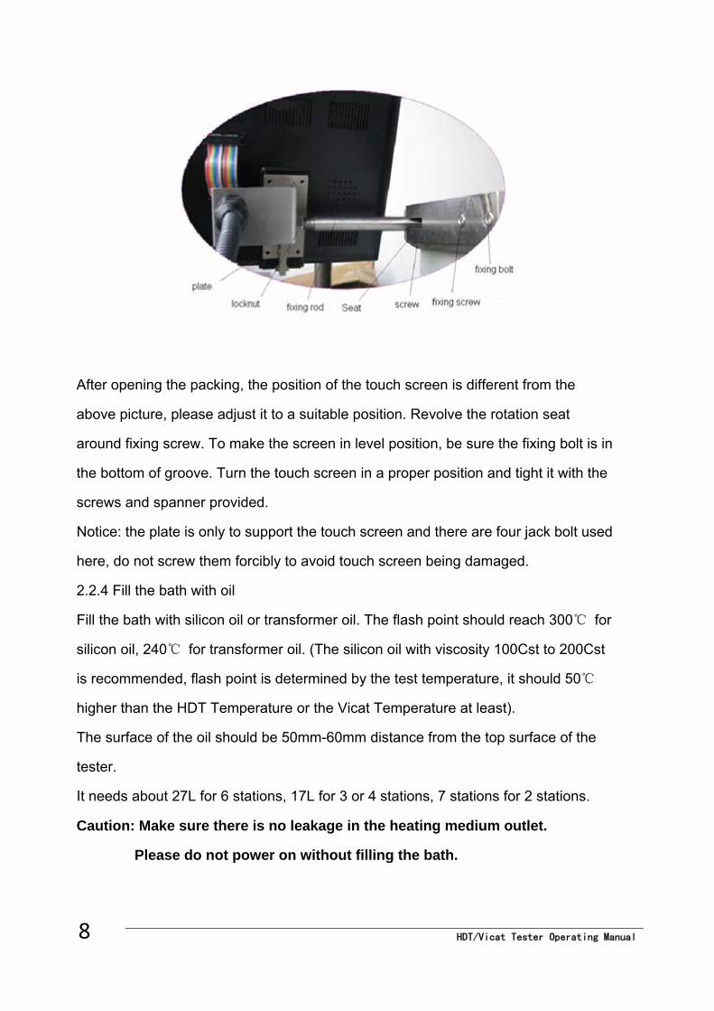
2.2.3 Turn the touch screen in a proper position, and tight it to prevent its excursion
and vibration.
HDT/Vicat Tester Operating Manual 8
After opening the packing, the position of the touch screen is different from the
above picture, please adjust it to a suitable position. Revolve the rotation seat
around fixing screw. To make the screen in level position, be sure the fixing bolt is in
the bottom of groove. Turn the touch screen in a proper position and tight it with the
screws and spanner provided.
Notice: the plate is only to support the touch screen and there are four jack bolt used
here, do not screw them forcibly to avoid touch screen being damaged.
2.2.4 Fill the bath with oil
Fill the bath with silicon oil or transformer oil. The flash point should reach 300℃ for
silicon oil, 240℃ for transformer oil. (The silicon oil with viscosity 100Cst to 200Cst
is recommended, flash point is determined by the test temperature, it should 50℃
higher than the HDT Temperature or the Vicat Temperature at least).
The surface of the oil should be 50mm-60mm distance from the top surface of the
tester.
It needs about 27L for 6 stations, 17L for 3 or 4 stations, 7 stations for 2 stations.
Caution: Make sure there is no leakage in the heating medium outlet.
Please do not power on without filling the bath.
HDT/Vicat Tester Operating Manual
9
2.2.5 Place the tester stations into the bath
The test stations are supplied separate from the instrument to minimize the risk of
damage during shipment. They are included in the accessory box.
Install the stations one by one. Connect the micrometer and instrument with the wire.
2.2.6 Please check the cable connection carefully; especially, the power cord must
be single-phase three-wire in case electric shock.
The tester is equipped with circuit breakers.
Section 3—Component The tester consists of main frame and supplied accessories.
3.1 Main frame
The main frame consists of stirring part, oil bath, temperature measurement system,
displacement measurement system, safeguards part, data storage and touch screen
displaying.
3.1.1 Stirring part
With the function of Baffle plate and the stirring motor inside oil tank, the oil will
perform a closed cycle movement in the oil tank, which ensures the uniformity of
temperature field.
3.1.2 Oil bath
The mineral wool is used to insulate heat; stream guidance design ensures the
uniformity of temperature, also the test possesses a piece of condensation pipe
which allows water cooling below 150℃.
3.1.3 Temperature measurement system
The high accuracy temperature sensor is introduced to the temperature
measurement system. The temperature calibration can be accomplished by the
software of the tester, instead of adjusting the hardware, ensuring the temperature
display value in accordance with the actual value. This part adopts precision
HDT/Vicat Tester Operating Manual 10
resistance and technical grade chips, making the temperature unrelated to the
hardware. The recover button in the calibration interface makes the operate miss
during calibration can be recovered to the default setting, ensuring maintainability of
the tester.
3.1.3 Temperature measuring part adopts high precision temperature sensor,
together with the function of temperature calibration controlled by software, make
sure the accuracy of temperature. At the same time, the hard ware--- precision
resistance and technical grade chip
3.1.4 Temperature control adopts PID control system, the range is from room
temperature to 300℃, the control accuracy is ±0.5℃.
3.1.5 Displacement measurement system adopts dial gauge and microcontroller
corresponding, so it is reliable. Also, modular structures makes replace easy.
3.1.6 Safeguard part
In order to protect operator and the instrument itself, this HDT/Vicat tester has been
equipped with double-protection function.
One is from software protection : when testing temperature is up to upper limit value,
system will stop heating automatically; the other protection function is from
“temperature switch”: If there is something wrong with software and it can not control
temperature correctly, the temperature switch protection function will be used .
When the Oil bath temperature is higher than set temperature, it will be powered off
by temperature switch.
Notice: Instrument temperature has been set well before leaving factory. Only
specified operator can modify it according to the local low or regulation. At this
condition, password is also necessary .
3.1.7 Testing data storage part:
This type of tester adopts removable storage device, which can be contacted will
instrument via USB 2.0, then all the testing data can be saved into this device.
3.1.8 Display part: It consists of main control interface, calibration interface, setting
interface, testing result view interface and so on.
3.2 Accessory
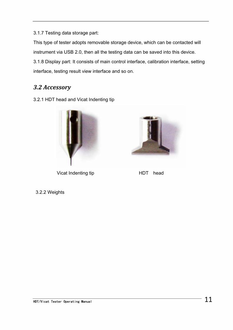
3.2.1 HDT head and Vicat Indenting tip
Vicat Indenting tip HDT head
3.2.2 Weights
11 HDT/Vicat Tester Operating Manual
HDT/Vicat Tester Operating Manual 12
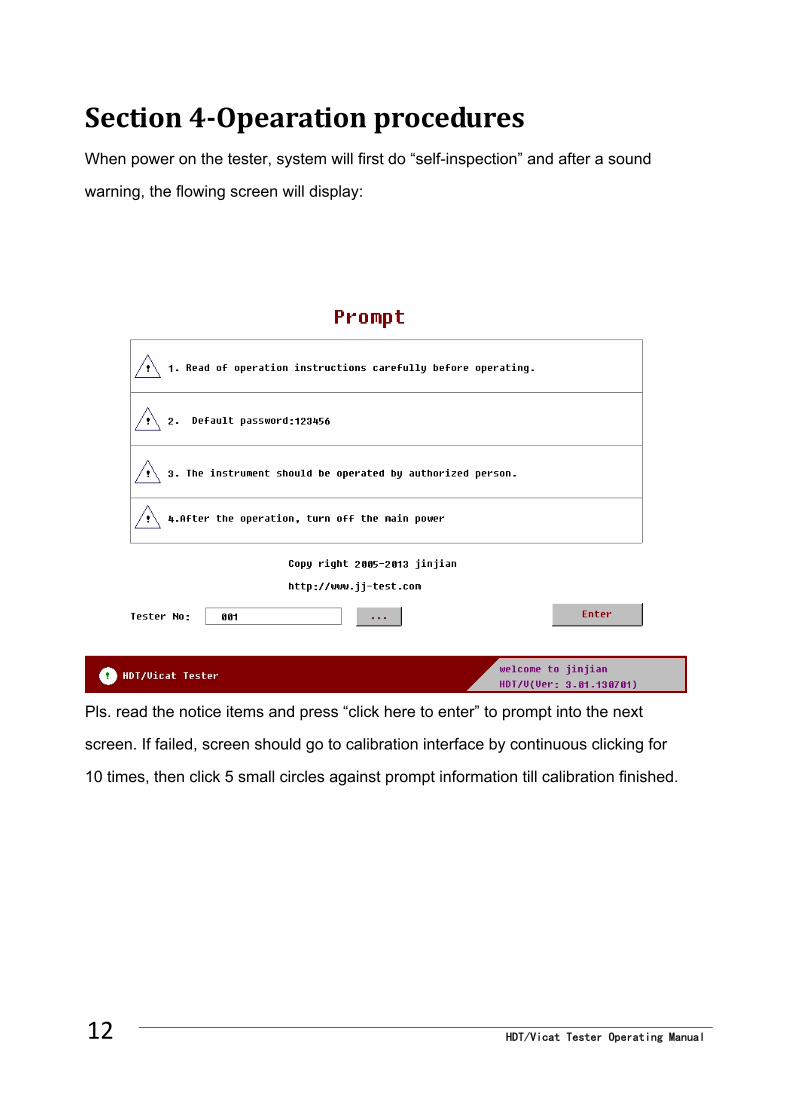
Section 4-Opearation procedures When power on the tester, system will first do “self-inspection” and after a sound
warning, the flowing screen will display:
Pls. read the notice items and press “click here to enter” to prompt into the next
screen. If failed, screen should go to calibration interface by continuous clicking for
10 times, then click 5 small circles against prompt information till calibration finished.
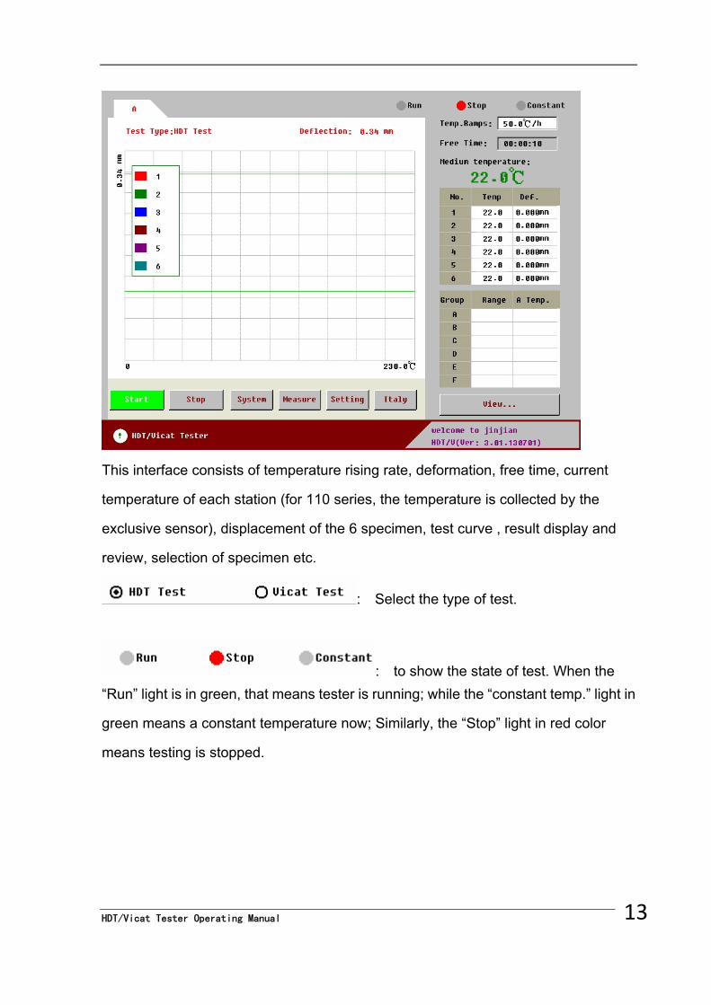
This interface consists of temperature rising rate, deformation, free time, current
temperature of each station (for 110 series, the temperature is collected by the
exclusive sensor), displacement of the 6 specimen, test curve , result display and
review, selection of specimen etc.
: Select the type of test.
: to show the state of test. When the
“Run” light is in green, that means tester is running; while the “constant temp.” light in
green means a constant temperature now; Similarly, the “Stop” light in red color
means testing is stopped.
13 HDT/Vicat Tester Operating Manual
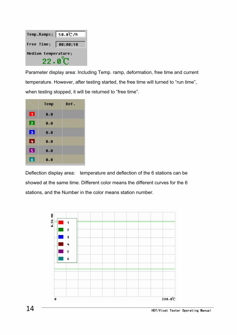
HDT/Vicat Tester Operating Manual 14
Parameter display area: Including Temp. ramp, deformation, free time and current
temperature. However, after testing started, the free time will turned to “run time”,
when testing stopped, it will be returned to “free time”.
Deflection display area: temperature and deflection of the 6 stations can be
showed at the same time. Different color means the different curves for the 6
stations, and the Number in the color means station number.
X-coordinate: temperature
Y-coordinate: displacement
Upper green line: zero
Lower green line: displacement at set point
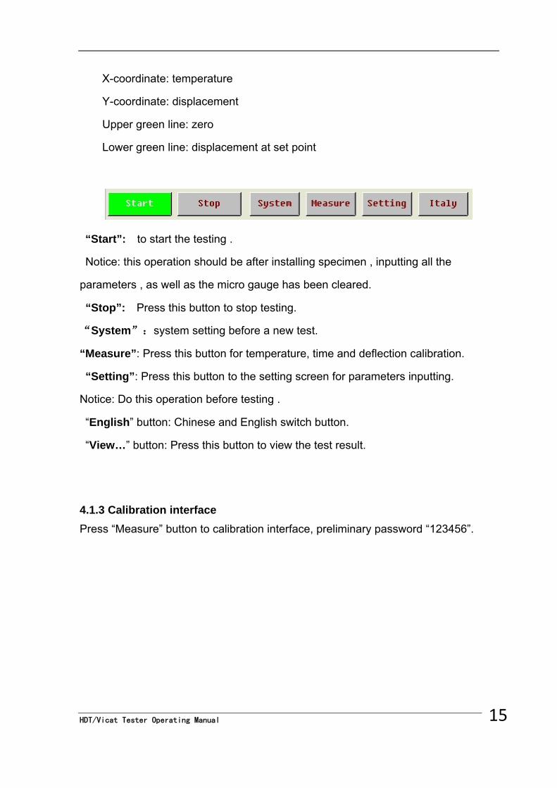
“Start”: to start the testing .
Notice: this operation should be after installing specimen , inputting all the
parameters , as well as the micro gauge has been cleared.
“Stop”: Press this button to stop testing.
“System”:system setting before a new test.
“Measure”: Press this button for temperature, time and deflection calibration.
“Setting”: Press this button to the setting screen for parameters inputting.
Notice: Do this operation before testing .
“English” button: Chinese and English switch button.
“View…” button: Press this button to view the test result.
4.1.3 Calibration interface
Press “Measure” button to calibration interface, preliminary password “123456”.
15 HDT/Vicat Tester Operating Manual
HDT/Vicat Tester Operating Manual 16
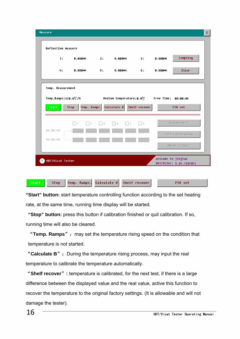
“Start” button: start temperature controlling function according to the set heating
rate, at the same time, running time display will be started.
“Stop” button: press this button if calibration finished or quit calibration. If so,
running time will also be cleared.
“Temp. Ramps”:may set the temperature rising speed on the condition that
temperature is not started.
“Calculate B”:During the temperature rising process, may input the real
temperature to calibrate the temperature automatically.
“Shelf recover”: temperature is calibrated, for the next test, if there is a large
difference between the displayed value and the real value, active this function to
recover the temperature to the original factory settings. (It is allowable and will not
damage the tester).
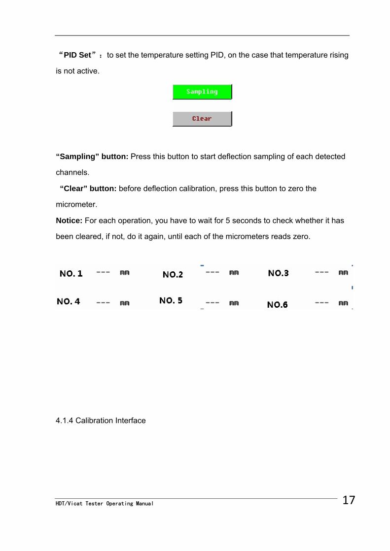
“PID Set”:to set the temperature setting PID, on the case that temperature rising
is not active.
“Sampling” button: Press this button to start deflection sampling of each detected
channels.
“Clear” button: before deflection calibration, press this button to zero the
micrometer.
Notice: For each operation, you have to wait for 5 seconds to check whether it has
been cleared, if not, do it again, until each of the micrometers reads zero.
4.1.4 Calibration Interface
17 HDT/Vicat Tester Operating Manual
HDT/Vicat Tester Operating Manual 18
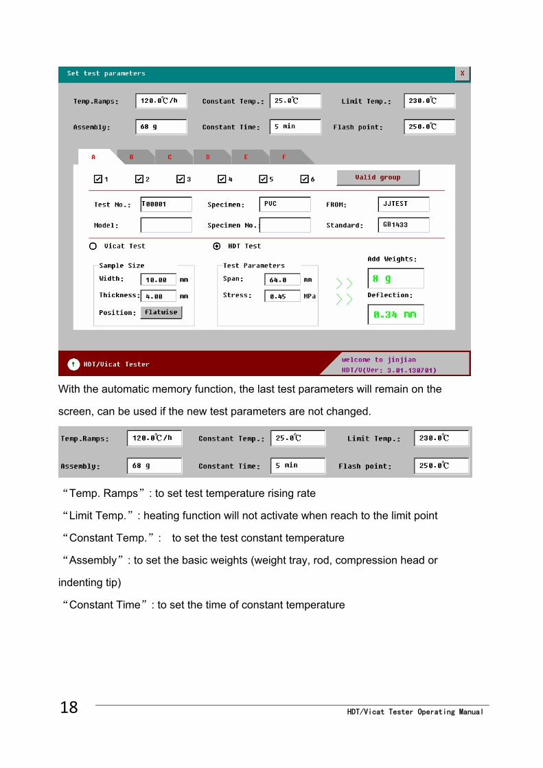
With the automatic memory function, the last test parameters will remain on the
screen, can be used if the new test parameters are not changed.
“Temp. Ramps”: to set test temperature rising rate
“Limit Temp.”: heating function will not activate when reach to the limit point
“Constant Temp.”: to set the test constant temperature
“Assembly”: to set the basic weights (weight tray, rod, compression head or
indenting tip)
“Constant Time”: to set the time of constant temperature
Note: if Constant time is set as “0”, temperature will rise up without constant
temperature control; if “Constant time” is set, system will first perform constant
temperature control till set time, then proceed to rise up.
“Flash point”:to set the flash point of medium oil
“ ” :Quit calibration interface, all the settings are saved automatically.
Choose any group to the following setting interface
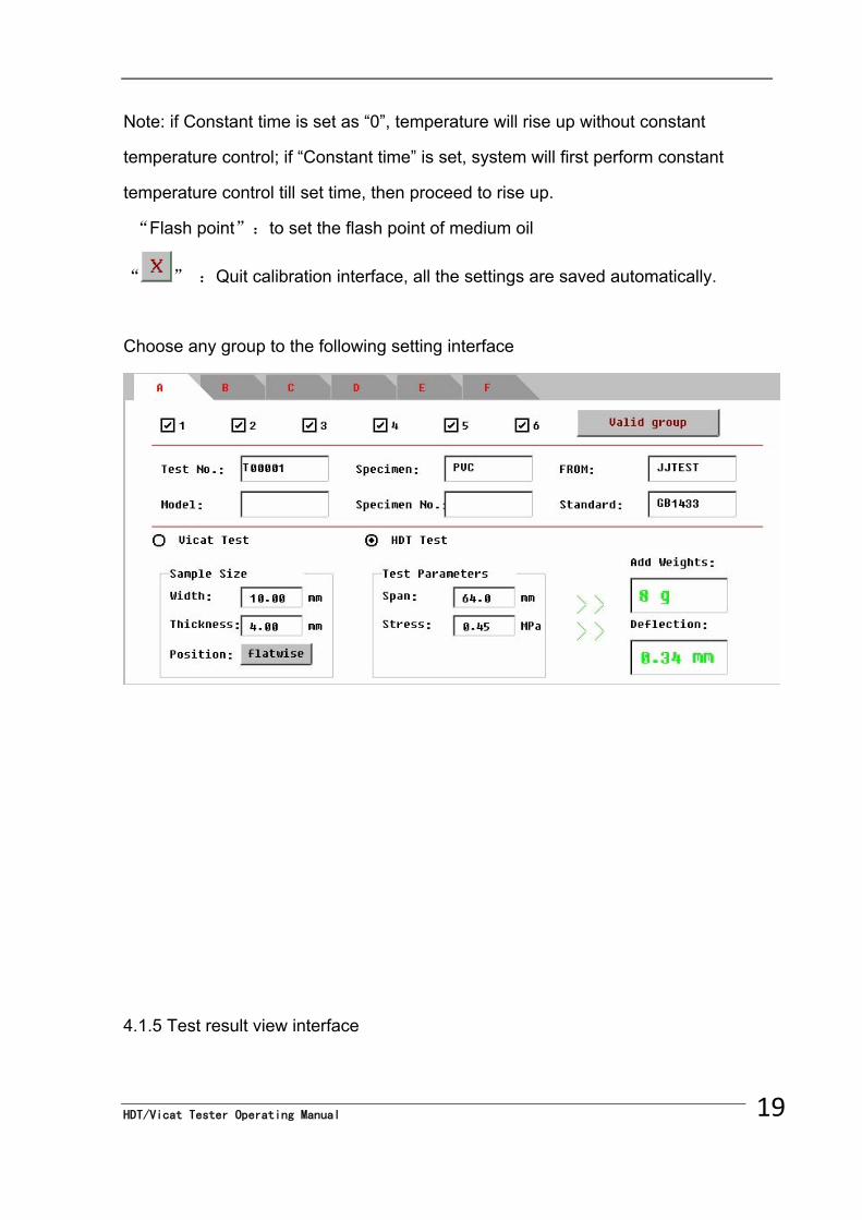
4.1.5 Test result view interface
19 HDT/Vicat Tester Operating Manual
HDT/Vicat Tester Operating Manual 20
Above interface is blank, if go to view interface directly when powered on, the last
finished test result will be displayed.
4.1.6 Setting interface
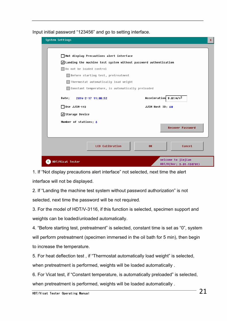
Input initial password “123456” and go to setting interface.
1. If “Not display precautions alert interface” not selected, next time the alert
interface will not be displayed.
2. If “Landing the machine test system without password authorization” is not
selected, next time the password will be not required.
3. For the model of HDT/V-3116, if this function is selected, specimen support and
weights can be loaded/unloaded automatically.
4. “Before starting test, pretreatment” is selected, constant time is set as “0”, system
will perform pretreatment (specimen immersed in the oil bath for 5 min), then begin
to increase the temperature.
5. For heat deflection test , if “Thermostat automatically load weight” is selected,
when pretreatment is performed, weights will be loaded automatically .
HDT/Vicat Tester Operating Manual 21
6. For Vicat test, if “Constant temperature, is automatically preloaded” is selected,
when pretreatment is performed, weights will be loaded automatically .
HDT/Vicat Tester Operating Manual 22
7. Select “Use JJSM-113” and input the JJSM host ID, specimen sizes will be read
into the screen automatically.
8. Select “Storage device” to save the testing result at a file, together with the PC
software supplied, testing result can be exported, also the result can be re-edited or
printed out. Otherwise, if the testing report is not exported, all the data will disappear
as is powered off.
9. “Number of stations”: the number of test stations this machine has.
10. default password is “123456”
Click “OK” to save the settings and go back to main interface.
Note: Items of 3,4,5,6 are only suitable fore HDT/V-3116 model.
4.2 specimen preparation and installation
4.2.1 Vicat specimen
4.2.1.1 At least two test specimens shall be used to test each sample. The test
specimens shall between 3mm and 6.5mm thick and at least 10mm by 10mm in area
or 10 mm in diameter. They shall be made in accordance with the specifications, if
any, for the material under test. In the absence of such specifications, any suitable
procedure may be used for the preparation of test specimens.
For sheet materials, the thickness of the test specimens shall be equal to thickness
of the sheet, expect as follows:
a) If the thickness exceeds 6.5mm, the test specimens shall be reduced in thickness
to 3mm to 6.5mm by machining one surface (See ISO 2818), the other surface being
left intact. The test surface shall be the intact one.
b) If the thickness of the sheet is less than 3mm, not more than poeces shall be
stacked together in direct contact to give a total thickness between 3mm and 6.5mm
and the thickness of the upper piece shall be at least 1.5mm. Stacking of pieces of
lesser thickness does not always give the same test result.
4.2.2 HDT Test Specimen
HDT/Vicat Tester Operating Manual
23
At least two test specimens shall be used to test each sample. Each test specimen
shall be a bar of rectangular cross-section (Length l, width b, thickness h). The
dimensions of the test specimen shall be as specified in the relevant part of ISO75.
Notice: The standard dimension is : (80×10×4)mm
4.2.3 Specimen installation
4.2.3.1 Take the test station out of the bath by holding the two handles. Turn the
knob and place the specimen on the plane of the station. Turn back the knob to lock
the specimen
4.2.3.2 Hold the two handle and immerse test station into Oil bath, specimen should
be located 35mm under oil.
4.2.3.3 According to the standard and specimen to calculate the weights and put
them on the loading carrying plate.
For VICAT test, place the test station to the bath and wait for about 5mins, then
place all the necessary weights, last power on. .
For HDT test, place the test station to the bath and place the necessary weights at
once, next wait for about 5mins. Last step power on.
CAUTION: Do not turn the knob after installing the specimen to avoid weights falling
off.
4.3 Weights and deflection settings
4.3.1 Weights settings:
4.3.1.1 Weights calculation for HDT test:
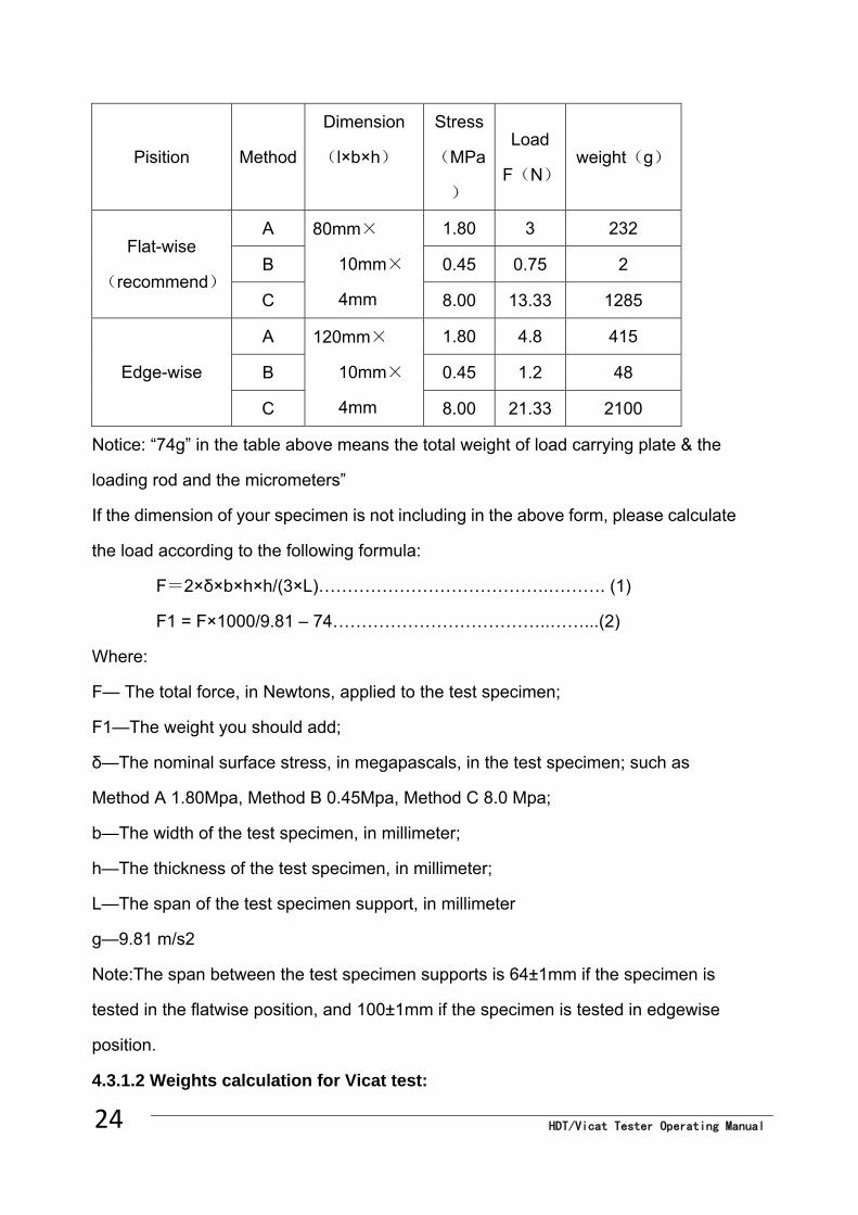
HDT/Vicat Tester Operating Manual 24
Pisition Method
Dimension
(l×b×h)
Stress
(MPa
)
Load
F(N)weight(g)
A 1.80 3 232
B 0.45 0.75 2 Flat-wise
(recommend) C
80mm×
10mm×
4mm 8.00 13.33 1285
A 1.80 4.8 415
B 0.45 1.2 48 Edge-wise
C
120mm×
10mm×
4mm 8.00 21.33 2100
Notice: “74g” in the table above means the total weight of load carrying plate & the
loading rod and the micrometers”
If the dimension of your specimen is not including in the above form, please calculate
the load according to the following formula:
F=2×δ×b×h×h/(3×L)………………………………….………. (1)
F1 = F×1000/9.81 – 74………………………………..……...(2)
Where:
F— The total force, in Newtons, applied to the test specimen;
F1—The weight you should add;
δ—The nominal surface stress, in megapascals, in the test specimen; such as
Method A 1.80Mpa, Method B 0.45Mpa, Method C 8.0 Mpa;
b—The width of the test specimen, in millimeter;
h—The thickness of the test specimen, in millimeter;
L—The span of the test specimen support, in millimeter
g—9.81 m/s2
Note:The span between the test specimen supports is 64±1mm if the specimen is
tested in the flatwise position, and 100±1mm if the specimen is tested in edgewise
position.
4.3.1.2 Weights calculation for Vicat test:
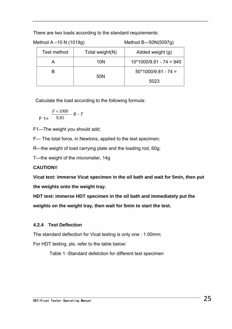
There are two loads according to the standard requirements:
Method A –10 N (1019g) Method B—50N(5097g)
Test method Total weight(N) Added weight (g)
A 10N 10*1000/9.81 - 74 = 945
B 50N
50*1000/9.81 - 74 =
5023
Calculate the load according to the following formula:
F 1= TR
F
81.91000
F1—The weight you should add;
F— The total force, in Newtons, applied to the test specimen;
R—the weight of load carrying plate and the loading rod, 60g;
T—the weight of the micrometer, 14g
CAUTION!!
Vicat test: immerse Vicat specimen in the oil bath and wait for 5min, then put
the weights onto the weight tray.
HDT test: immerse HDT specimen in the oil bath and immediately put the
weights on the weight tray, then wait for 5min to start the test.
4.2.4 Test Deflection
The standard deflection for Vicat testing is only one : 1.00mm;
For HDT testing, pls. refer to the table below:
Table 1 -Standard defelction for different test specimen
25 HDT/Vicat Tester Operating Manual
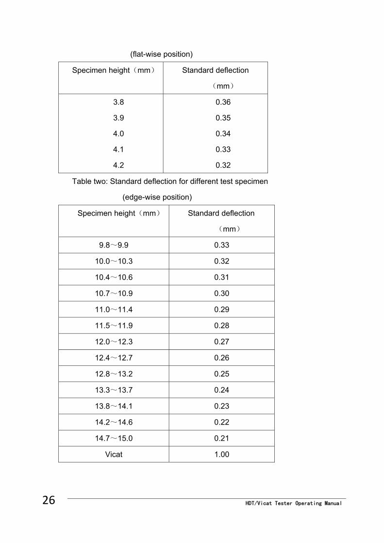
HDT/Vicat Tester Operating Manual 26
(flat-wise position)
Specimen height(mm) Standard deflection
(mm)
3.8
3.9
4.0
4.1
4.2
0.36
0.35
0.34
0.33
0.32
Table two: Standard deflection for different test specimen
(edge-wise position)
Specimen height(mm) Standard deflection
(mm)
9.8~9.9 0.33
10.0~10.3 0.32
10.4~10.6 0.31
10.7~10.9 0.30
11.0~11.4 0.29
11.5~11.9 0.28
12.0~12.3 0.27
12.4~12.7 0.26
12.8~13.2 0.25
13.3~13.7 0.24
13.8~14.1 0.23
14.2~14.6 0.22
14.7~15.0 0.21
Vicat 1.00
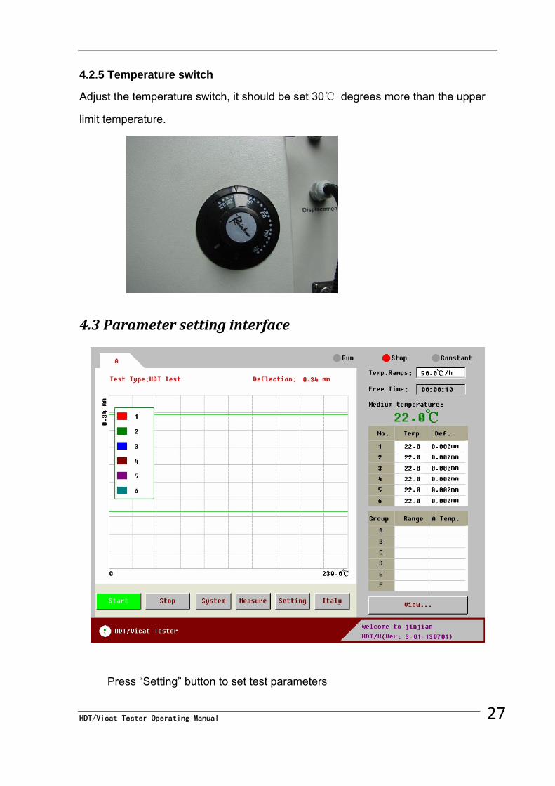
4.2.5 Temperature switch
Adjust the temperature switch, it should be set 30℃ degrees more than the upper
limit temperature.
4.3 Parameter setting interface
Press “Setting” button to set test parameters
27 HDT/Vicat Tester Operating Manual
HDT/Vicat Tester Operating Manual 28
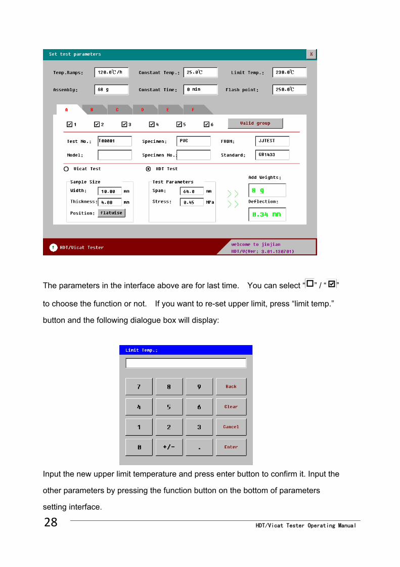
The parameters in the interface above are for last time. You can select “ ” / “ ”
to choose the function or not. If you want to re-set upper limit, press “limit temp.”
button and the following dialogue box will display:
Input the new upper limit temperature and press enter button to confirm it. Input the
other parameters by pressing the function button on the bottom of parameters
setting interface.
Notice: All the inputting parameters should be according to relative standards,
especially the deflection for HDT. For each parameter, there is a range for the
parameters, if the value input is not allowed in relative standard, It will turn up a
warning box and the parameters input will be invalid. Take heating rate as example,
if you have input an invalid value, the following warning information will turn up:
After parameter inputting, press to save parameters and back to testing
interface. Two reference lines will be described and displayed on touch screen (the
lower one is start line for deflection, while the upper one is set deflection. At this
area, the x-coordinate is for temperature ( 0℃~upper limit temperature);
y-coordinate is for -0.1~1.2×(set deflection).
After weight added, adjust micrometer to make sure its bottom contact with the
upper surface of weight. Depress micrometer by 3mm~5mm and fix it. Power on
tester and adjust the micrometer to make sure it is showed as below:
29 HDT/Vicat Tester Operating Manual
HDT/Vicat Tester Operating Manual 30
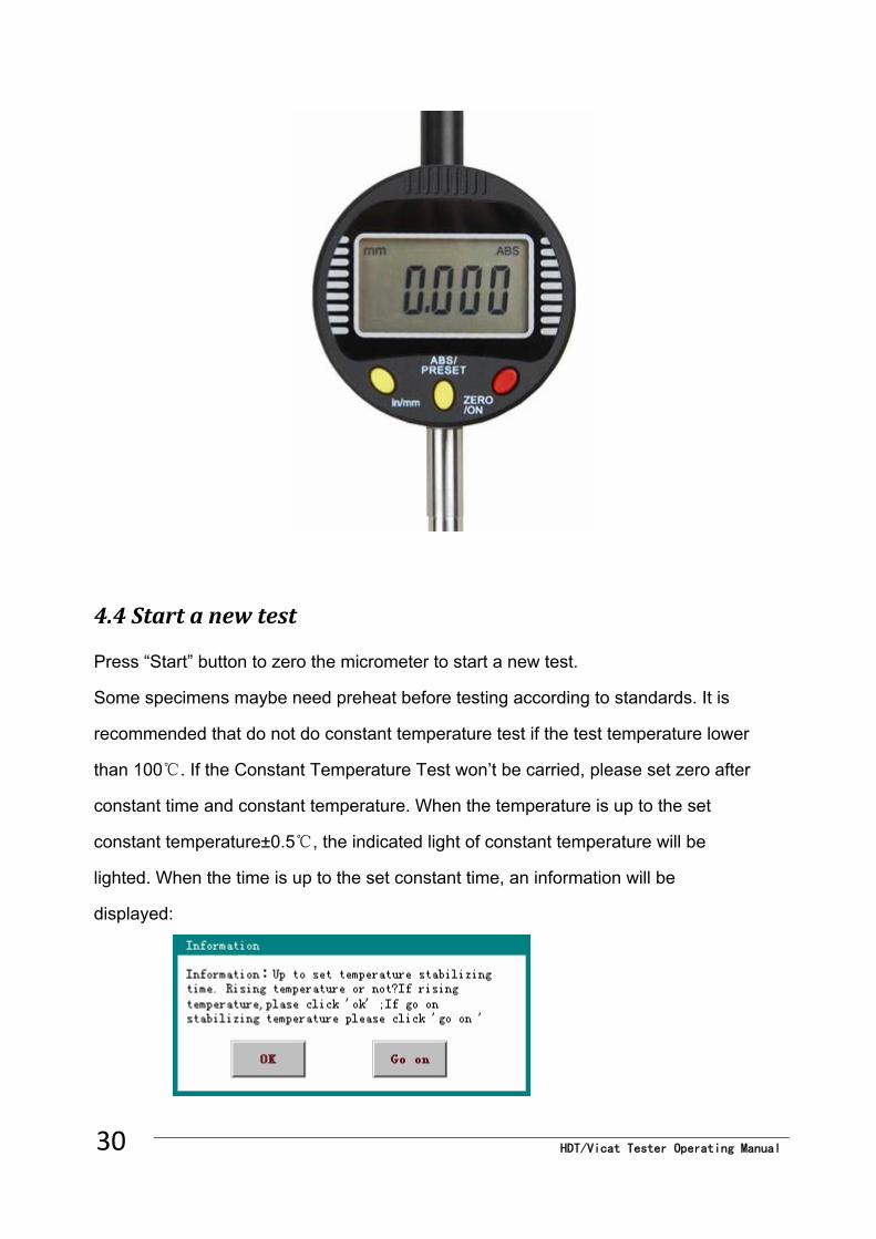
4.4 Start a new test
Press “Start” button to zero the micrometer to start a new test.
Some specimens maybe need preheat before testing according to standards. It is
recommended that do not do constant temperature test if the test temperature lower
than 100℃. If the Constant Temperature Test won’t be carried, please set zero after
constant time and constant temperature. When the temperature is up to the set
constant temperature±0.5℃, the indicated light of constant temperature will be
lighted. When the time is up to the set constant time, an information will be
displayed:
If you want to continue constant temperature, press “go on” button, while if you want
to start testing, press “yes” button; at the condition of maintain constant temperature,
if you want to stop constant temperature control and start to testing, press “start”
button to do it.
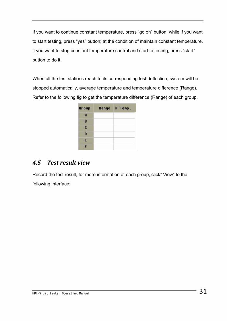
When all the test stations reach to its corresponding test deflection, system will be
stopped automatically, average temperature and temperature difference (Range).
Refer to the following fig to get the temperature difference (Range) of each group.
4.5 Test result view
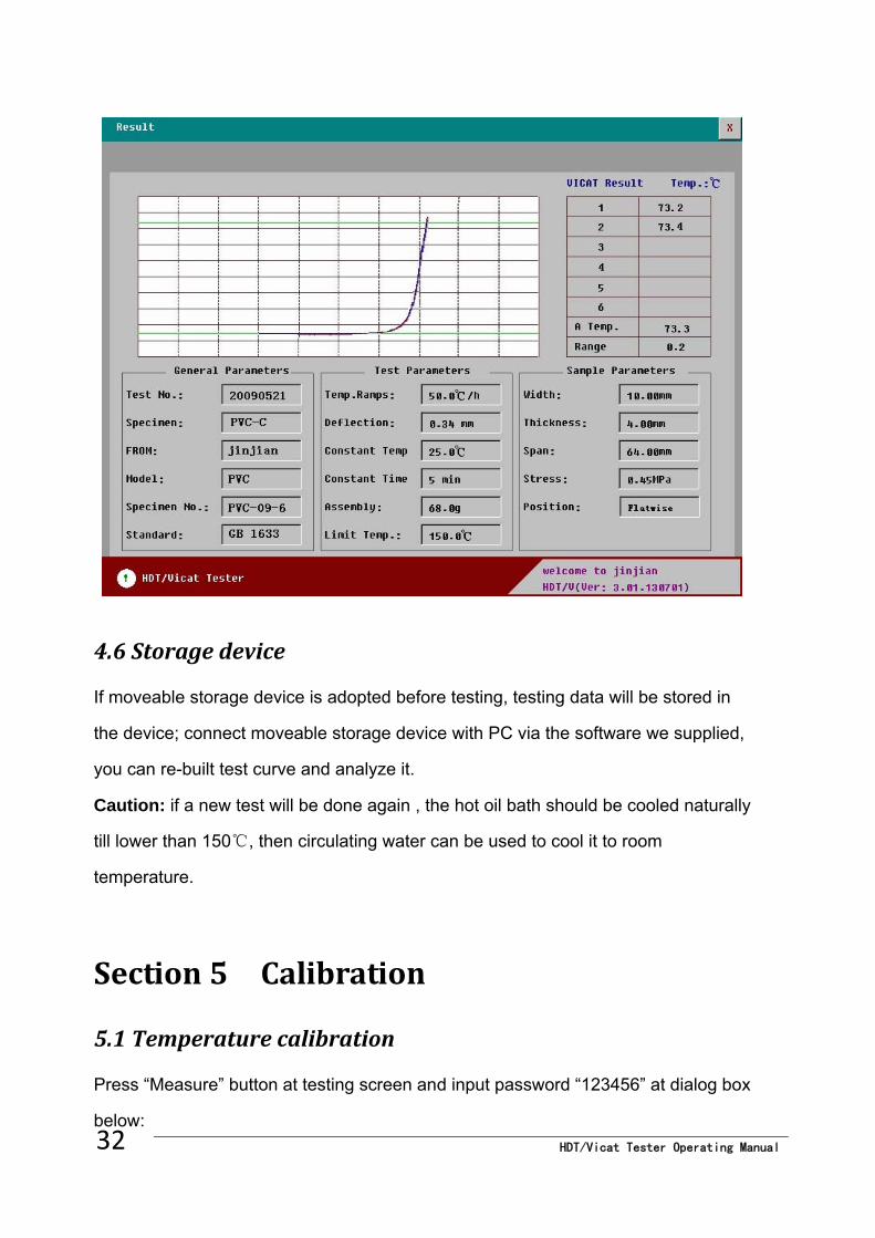
Record the test result, for more information of each group, click” View” to the
following interface:
31 HDT/Vicat Tester Operating Manual
HDT/Vicat Tester Operating Manual 32
4.6 Storage device
If moveable storage device is adopted before testing, testing data will be stored in
the device; connect moveable storage device with PC via the software we supplied,
you can re-built test curve and analyze it.
Caution: if a new test will be done again , the hot oil bath should be cooled naturally
till lower than 150℃, then circulating water can be used to cool it to room
temperature.
Section 5 Calibration
5.1 Temperature calibration
Press “Measure” button at testing screen and input password “123456” at dialog box
below:
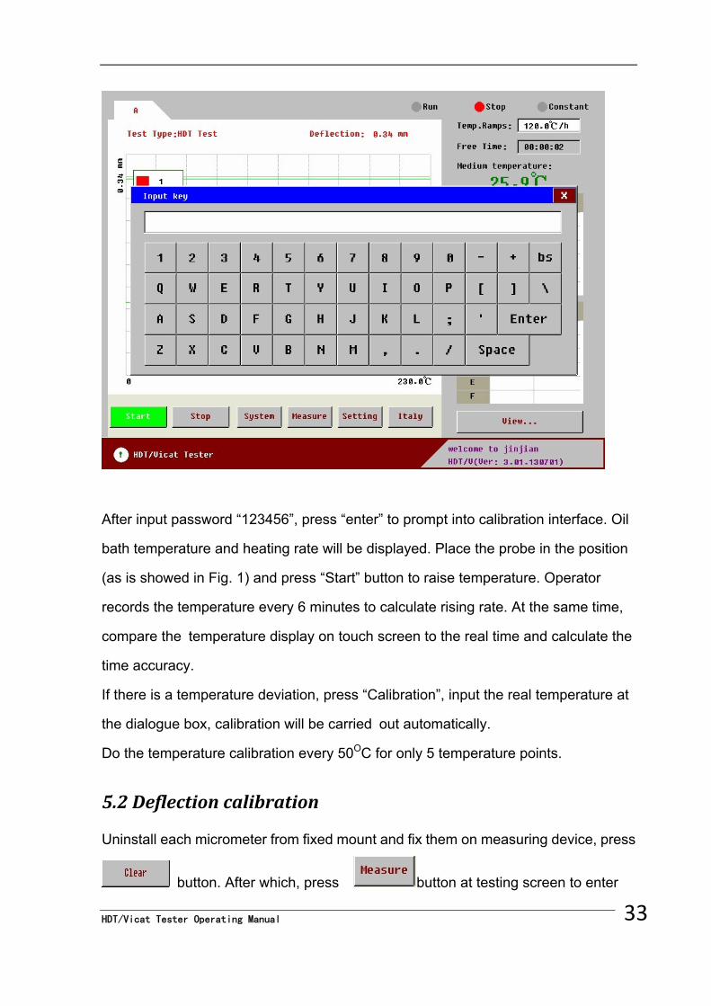
After input password “123456”, press “enter” to prompt into calibration interface. Oil
bath temperature and heating rate will be displayed. Place the probe in the position
(as is showed in Fig. 1) and press “Start” button to raise temperature. Operator
records the temperature every 6 minutes to calculate rising rate. At the same time,
compare the temperature display on touch screen to the real time and calculate the
time accuracy.
If there is a temperature deviation, press “Calibration”, input the real temperature at
the dialogue box, calibration will be carried out automatically.
Do the temperature calibration every 50OC for only 5 temperature points.
5.2 Deflection calibration
Uninstall each micrometer from fixed mount and fix them on measuring device, press
button. After which, press button at testing screen to enter
33 HDT/Vicat Tester Operating Manual
HDT/Vicat Tester Operating Manual 34
into calibration interface. Then press button, deflection for each station
will be displayed, and check whether deflection calibration is needed.
Section 6 Trouble shootings 6.1 No heating during the temperature rising.
Please return to the setting screen and check whether the upper limit of temperature
is too low or not. If not, please check the settings of the temperature switch.
6.2 There is abnormal of the temperature rate
There may be impurity in the heating medium. Please clean the oil bath.
6.3 No data of displacement
Please stop test and check the test station choosing or reconnect the communication
cable.
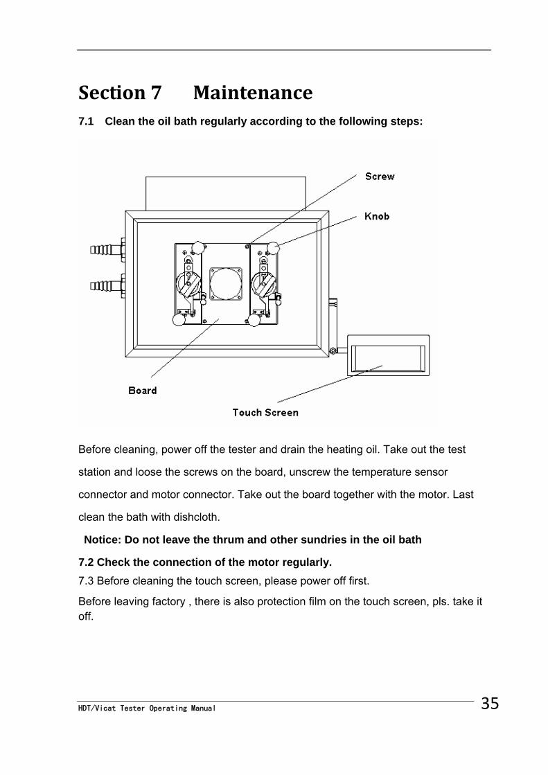
Section 7 Maintenance 7.1 Clean the oil bath regularly according to the following steps:
Before cleaning, power off the tester and drain the heating oil. Take out the test
station and loose the screws on the board, unscrew the temperature sensor
connector and motor connector. Take out the board together with the motor. Last
clean the bath with dishcloth.
Notice: Do not leave the thrum and other sundries in the oil bath
7.2 Check the connection of the motor regularly.
7.3 Before cleaning the touch screen, please power off first.
Before leaving factory , there is also protection film on the touch screen, pls. take it off.
35 HDT/Vicat Tester Operating Manual


![Dimensional Analysis hdt [????]](https://img.pdfslide.us/doc/110x75/61e0111627d16074d07ac3cb/dimensional-analysis-hdt-.jpg)