Embed Size (px)
Citation preview

HiD2000 Intrinsic Safety
Isolators & Signal RepeatersPR
OCES
SAU
TOM
ATIO
N
2
Index
About Us... 3
HiD2000 System Overview 4-5
Flexible Split Termination Boards 6
Custom Solutions & Features 7
Signal Marshalling Philosophy Using Cross-Wiring 8
The Pepperl+Fuchs Elcon System Concept 9
Model Selection 10
Modules Data Sheets HiD2000 11-29
Module Data Sheet Mux2700 30-31
General Specification & Approvals 32
Termination Board & Module Specification 33
Termination Board Dimensional Drawings 34
Termination Board Structure & Accessories 35
Do You Need a DIN-Rail Solution? 36
K-System Features 37
PS 1550 - Power Supply Details 38-42

3
About Us...
For over 25 years, Elcon Instruments have been a world leader inIntrinsic Safety (I.S.) interface techniques for the process industry.
In 2001, Elcon Instruments joined thePepperl+Fuchs Group of companies witha mission to provide our customers witha diverse range of specialised IntrinsicSafety and general purpose I/O Interfaceproducts.
Our joint product portfolio is now sup-ported by our large international salesand technical support team, which isavailable to provide assistance for yourprocess automation needs.
Company milestones include:
In 1974, the design and certification of what is thought to be theworld’s first intrinsic safety galvanic isolator, a technique nowwidely used as the world’s standard I.S. interface method.
Late 1980’s, Elcon pioneered a new plug-in I.S. interface concept,using multi-channel modules plugged onto a PCB terminationboard. The board incorporated multi-core cable connectors,customised to match the I/O cards of the world’s major processcontrol systems. This innovative concept provided major cabinetand cable cost savings.
In the early 1990’s, Elcon introduced the first integrated HART®
interface solution, using a Multiplexer module which mounteddirectly on field wiring termination board for both I.S. and non I.S.signals. This permitted the use of PC based PAM (Plant AssetManagement) software for field device set up, monitoring andmaintenance, of all HART® field devices.
Today we are known as Pepperl+Fuchs Elcon, focusing on thedevelopment of I/O interface solutions for the emerging Fieldbusenvironment and other applications.
We look forward in assisting you with a solution to suit your process needs.

4
HiD2000
FaultMonitoring
Modules monitor field
wiring faults and output a
common alarm to assist
in maintenance.
TerminalOptions
Use multi level terminal
blocks (HAT) or choose the
optional knife edge loop
disconnect terminals with
integral test jacks
(HAKE).
Quick-Lok Modules
No wiring on modules,
and no tools are required
to plug the modules on
the termination board,
simply plug-in and lock
by pushing down on
the Quick-Lok tabs!
Supply ConnectionsRedundant 24Vdc reverse polarity
protected and fault bus connectors both
with LED indication.
LED Status IndicatorsModule status and power-on indicators for
monitoring module operation and
highlighting loop wiring faults.
TaggingProvided on the front of every module,
terminal strip and termination board.
5
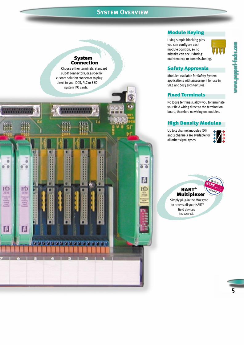
System Overview
SystemConnection
Choose either terminals, standard
sub-D connectors, or a specific
custom solution connector to plug
direct to your DCS, PLC or ESD
system I/O cards.
HART®
MultiplexerSimply plug-in the Mux2700
to access all your HART®
field devices (see page 30).
Module KeyingUsing simple blocking pins
you can configure each
module position, so no
mistake can occur during
maintenance or commissioning.
Safety ApprovalsModules available for Safety System
applications with assessment for use in
SIL2 and SIL3 architectures.
Fixed TerminalsNo loose terminals, allow you to terminate
your field wiring direct to the termination
board, therefore no wiring on modules.
High Density ModulesUp to 4 channel modules (DI)
and 2 channels are available for
all other signal types.
WE’VE GOT
ABILITY
FIELD COMMUNICATIONS PROTOCOL
6
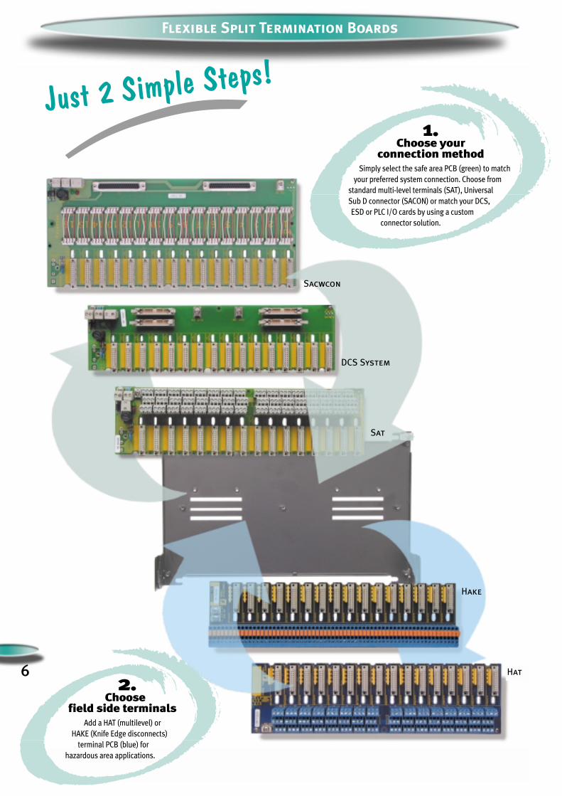
Flexible Split Termination Boards
Just 2 Simple Steps!
1.Choose your
connection methodSimply select the safe area PCB (green) to match
your preferred system connection. Choose from
standard multi-level terminals (SAT), Universal
Sub D connector (SACON) or match your DCS,
ESD or PLC I/O cards by using a custom
connector solution.
Hat
Hake
Sat
DCS System
Sacwcon
2.Choose
field side terminals Add a HAT (multilevel) or
HAKE (Knife Edge disconnects)
terminal PCB (blue) for
hazardous area applications.

Custom Solutions & Features
Do you have a solution
for my control system? Yes!! Custom Solutions are available for all
major DCS, ESD and PLC systems on the
market today. If we do not have a solution
for you, we will design one to your
specifications.
7
Can I mix I.S. and non I.S.
signals together? Yes! Using our 2900TOP entry modules, you
can mix I.S. and non I.S. signals on the same
termination board while maintaining the
necessary cable segregation.
How canI connect my
PAM software? Simply plug on the Mux2700
HART® multiplexer to access all
your HART® field devices.
Can I replacemy proprietary FTP?
Yes, it is now redundant, our HiD2000
emulates the standard FTP (Field
Termination Panels) in every way. Just
plug to our termination board using
standard system cables.
Simply Choose a Solution
Direct Custom Interface Solutions are available
for the most common DCS, PLC and ESD systems available on the market.
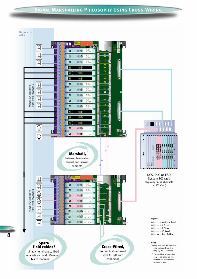
DCS, PLC or ESDSystem I/O rack
(Typically 16-32 channelsper I/O Card)
Mix
ed I/O
Mul
tico
refrom
fie
ld loc
atio
n 1
Mix
ed I/O
Mul
tico
refrom
fie
ld loc
atio
n 2
Notes:1) Only one wire per signal is
drawn crossed wired tosimplify the illustration.
2) Cross-wiring is an optiononly, if not required thetermination board widthreduces in size.
HazardousArea
IP
IP
IP
PW
RO
N
CH
1
CH
2
2 Channel
Contact/
Proxim
ityS
ensorR
epeater
2842
FAU
LTS
TAT
US
PW
RO
N
CH
1
CH
2
2 Channel
Contact/
Proxim
ityS
ensorR
epeater
2842
FAU
LTS
TAT
US
Blank
Module
Series
2000B
lankM
odule
Series
2000B
lankM
odule
Series
2000
PW
RO
N
2 Channel
Sm
artA
nalogInput
Repeater
2026
PW
RO
N
2 Channel
Sm
artA
nalogInput
Repeater
2026
PW
RO
N
CH
1
CH
2
2 Channel
Contact/
Proxim
ityS
ensorR
epeater
2842
FAU
LTS
TAT
US
Blank
Module
Series
2000
PW
RO
N
CH
1
CH
2
2 Channel
Contact/
Proxim
ityS
ensorR
epeater
2842
FAU
LTS
TAT
US
Blank
Module
Series
2000
PW
RO
N
2 Channel
Sm
artA
nalogInput
Repeater
20262 C
hannelS
mart
Analog
Output
Driver
2038 PW
RO
N
CH
1
CH
2
FAU
LT
FAU
LT
PW
RO
N
CH
1
CH
2
2 Channel
Contact/
Proxim
ityS
ensorR
epeater
2842
FAU
LTS
TAT
US
PW
RO
N
CH
1
CH
2
2 Channel
Contact/
Proxim
ityS
ensorR
epeater
2842
FAU
LTS
TAT
US
PW
RO
N
2 Channel
Sm
artA
nalogInput
Repeater
2026
PW
RO
N
2 Channel
Sm
artA
nalogInput
Repeater
20262 C
hannelS
mart
Analog
Output
Driver
2038 PW
RO
N
CH
1
CH
2
FAU
LT
FAU
LT
2 Channel
Sm
artA
nalogO
utputD
river
2038 PW
RO
N
CH
1
CH
2
FAU
LT
FAU
LT
PW
RO
N
CH
1
CH
2
2 Channel
Contact/
Proxim
ityS
ensorR
epeater
2842
FAU
LTS
TAT
US
PW
RO
N
CH
1
CH
2
2 Channel
Contact/
Proxim
ityS
ensorR
epeater
2842
FAU
LTS
TAT
US
PW
RO
N
CH
1
CH
2
2 Channel
Contact/
Proxim
ityS
ensorR
epeater
2842
FAU
LTS
TAT
US
Blank
Module
Series
2000
PW
RO
N
CH
1
CH
2
2 Channel
Contact/
Proxim
ityS
ensorR
epeater
2842
FAU
LTS
TAT
US
Marshall,between terminationboard and across
cabinets.
Cross-Wired,to termination board
with AO I/O cardconnector.
Sparefield cables?
Simply terminate to fixedterminals and add HiD2000
blank modules.
Legend:
Color = non I.S. AI Signal
Color = AI Signal
Color = DI Signal
Color = AO Signal
Color = Spare Cables8
Signal Marshalling Philosophy Using Cross-Wiring
9
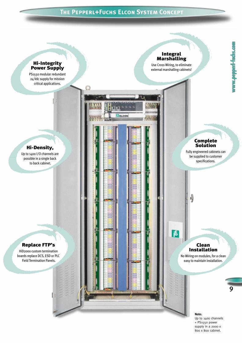
The Pepperl+Fuchs Elcon System Concept
Note: Up to 1400 channels+ PS1550 powersupply in a 2000 x800 x 800 cabinet.
Hi-Density,Up to 1400 I/O channels are
possible in a single back
to back cabinet.
Replace FTP’sHiD2000 custom termination
boards replace DCS, ESD or PLC
Field Termination Panels.
Integral Marshalling
Use Cross Wiring, to eliminate
external marshalling cabinets!
Clean Installation
No Wiring on modules, for a clean
easy to maintain installation.
Complete Solution
Fully engineered cabinets can
be supplied to customer
specifications.
Hi-Integrity Power Supply
PS1550 modular redundant
24 Vdc supply for mission
critical applications.

HiD2821HiD2822HiD2824
HiD2842HiD2844
DigitalIN 2
4
24
Dry Contact or Proximity Switch.
Dry Contact or Proximity Switch.
DPST relay per channel, Line Fault Detection.
SPST relay per channel, Line Fault Detection.
2 open-collector outputs per channel, Line Fault Detection.
1 open-collector output per channel, Line Fault Detection.
23
24
1 DPST relay for output and separate relay for LFD output.
Field Device Model Hazardous Area SignalNo. of Ch. Safe Area Signal Fault BusOutput
Page
HiD2012
HiD2025HiD2026
HiD2025skHiD2026sk
HiD2029HiD2030
HiD2029skHiD2030sk
AnalogIN
2
12
12
12
12
4-20 mA input, Smart capable.
4-20 mA (15.5 V) floating supply to Smart
or non-Smart two wire Transmitters.
4-20 mA (15.5 V) floating supply to Smart
or non-Smart two wire Transmitters.
4-20 mA (15.5 V) floating supply to Smart or
non-Smart two or three wire Transmitters.
4-20 mA (15.5 V) floating supply to Smart or
non-Smart two or three wire Transmitters.
4-20 mA (or 1-5 V) sink or source output isolated from input,
Smart compatible.
4-20 mA (or 1-5 V) output isolated from input,
Smart compatible.
4-20 mA load sink, isolated from input,
Smart compatible.
4-20 mA (or 1-5 V) output isolated from input and
power supply, Smart compatible, Line Fault Detection.
4-20 mA load sink, isolated from input and power supply,
Smart compatible, Line Fault Detection.
11
12
13
14
15
HiD2031HiD2032
HiD2033HiD2034
HiD2035HiD2036
HiD2037HiD2038HiD2038y
AnalogOUT
12
12
12
122
4-20 mA to I/P converters,
valve actuators and displays.
4-20 mA to I/P converters,
valve actuators and displays.
Fire, smoke detectors or I/P converters.
4-20 mA and Smart signal to I/P converters,
electrovalve actuators and displays.
Bus powered, 4-20 mA signal from DCS, PLC
or other control devices.
Loop powered, 4-20 mA signal from DCS, PLC
or other control devices.
Loop powered 1,5 to 50 mA signal from control devices.
Bus powered, 4-20 mA signal from DCS, PLC or other
control devices, Line Fault Detection, smart compatible.
Recommended for use with Yokogawa DCS systems.
16
17
18
19
20
21
22
HiD2061HiD2062
HiD2071HiD2072
HiD2082
12
12
2
Thermocouple or mV.
RTD or Potentiometer.
Thermocouple, mV, RTD or Potentiometer.
4-20 mA (or 1-5 V) output isolated from input.
4-20 mA (or 1-5 V) output isolated from input.
4-20 mA (or 1-5 V) sink or source output isolated from
input.
TemperatureIN
HiD2871HiD2872
HiD2873HiD2874
HiD2875HiD2876
HiD2877HiD2878
HiD2881
12
12
12
12
1
40 mA at 12 V to drive solenoid valve,
audible or visual alarm (LED).
40 mA at 12 V to drive solenoid valve,
audible or visual alarm (LED).
40 mA at 11,2 V to drive solenoid valve,
audible or visual alarm (LED).
40 mA at 11,2 V to drive solenoid valve,
audible or visual alarm (LED).
60 mA at 13 V to drive solenoid valve,
IIB Gas Group.
DigitalOUT
Bus powered, and/or loop powered, controlled by external
contact from DCS or control device.
Bus powered, controlled by external contact or logic
level from DCS or control device, Line Fault Detection.
Bus powered, and/or loop powered, controlled by external
contact from DCS or control device.
Bus powered, controlled by external contact or logic
level, from DCS or control device, Line Fault Detection.
Bus powered and/or loop powered, controlled by external contact
or logic level from DCS or control device, Line Fault Detection.
25
26
27
28
29
10
Model Selection
HiD2000 I.S. Isolator Range
11
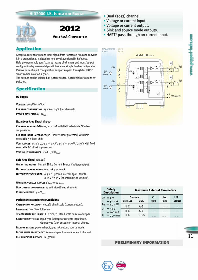
ApplicationAccepts a current or voltage input signal from Hazardous Area and converts
it in a proportional, isolated current or voltage signal in Safe Area.
Field programmable zero/span by means of trimmers and input/output
configuration by means of dip switches allow simple field reconfiguration.
Passive current input configuration supports a pass through for HART®
smart communication signals.
The outputs can be selected as current source, current sink or voltage by
switches.
Specification
DC Supply
Voltage: 20.4 V to 30 Vdc.
Current consumption: 25 mA at 24 V, (per channel).
Power dissipation: 1 WTyp.
Hazardous Area Signal (input)
Current ranges: 0-20 mA / 4-20 mA with field selectable DC offset
suppression.
Current input impedance: 50 Ω (overcurrent protected) with field
selectable 5 V level shift.
Volt ranges: 0-1 V / 0.2-1 V — 0-5 V / 1-5 V — 0-10 V / 2-10 V with field
selectable DC offset suppression.
Volt input impedance: 100K Ω/Volt input.
Safe Area Signal (output)
Operating modes: Current Sink / Current Source / Voltage output.
Output current range: 0-20 mA / 4-20 mA.
Output voltage range: 0-5 V / 1-5 V (on internal 250 Ω shunt).
0-10 V / 2-10 V (on internal 500 Ω shunt).
Working voltage range: 3 VMin to 30 VMax.
Max output compliance: 13 Volt (650 Ω load at 20 mA).
Ripple content: 15 mV rms.
Performance at Reference Conditions
Calibration accuracy: < ±0.1% of full scale (current output).
Linearity: < ±0.1% of full scale.
Temperature influence: < ±0.01%/°C of full scale on zero and span.
Selector switches: Input type (voltage or current), input levels.
Output type (sink or source), internal shunts.
Factory set as: 4-20 mA input, 4-20 mA output, source mode.
Front panel adjustment: Zero and span trimmers for each channel.
LED indicators: Power ON (green).
WE’VE GOT
ABILITY
FIELD COMMUNICATIONS PROTOCOL
• Dual (2012) channel.
• Voltage or current input.
• Voltage or current output.
• Sink and source mode outputs.
• HART® pass-through on current input.
HazardousArea
SafeArea
Model HiD2012
+
+ 1
4
VoltmA
Source
INCH 1
+11
14
OUTCH 1F RL
HHC
+ 2
5
VoltmA
Source
INCH 2
+12
15
OUTCH 2F RL
HHC
DC Supply Bus
F
SafetyDescription
Maximum External Parameters
Groups Co Lo L/RCenelec USA (µF) (mmH) (µH/Ω)
II C A-B _ _ _ _ _ _
II B C-E _ _ _ _ _ _
II A D-F-G _ _ _ _ _ _
2012Volt/mA Converter
PRELIMINARY INFORMATION
Uo = 2 VIo = 50 mAPo = 45 mW
Ui = 30 VIi = 100 mAPi = 750 mW
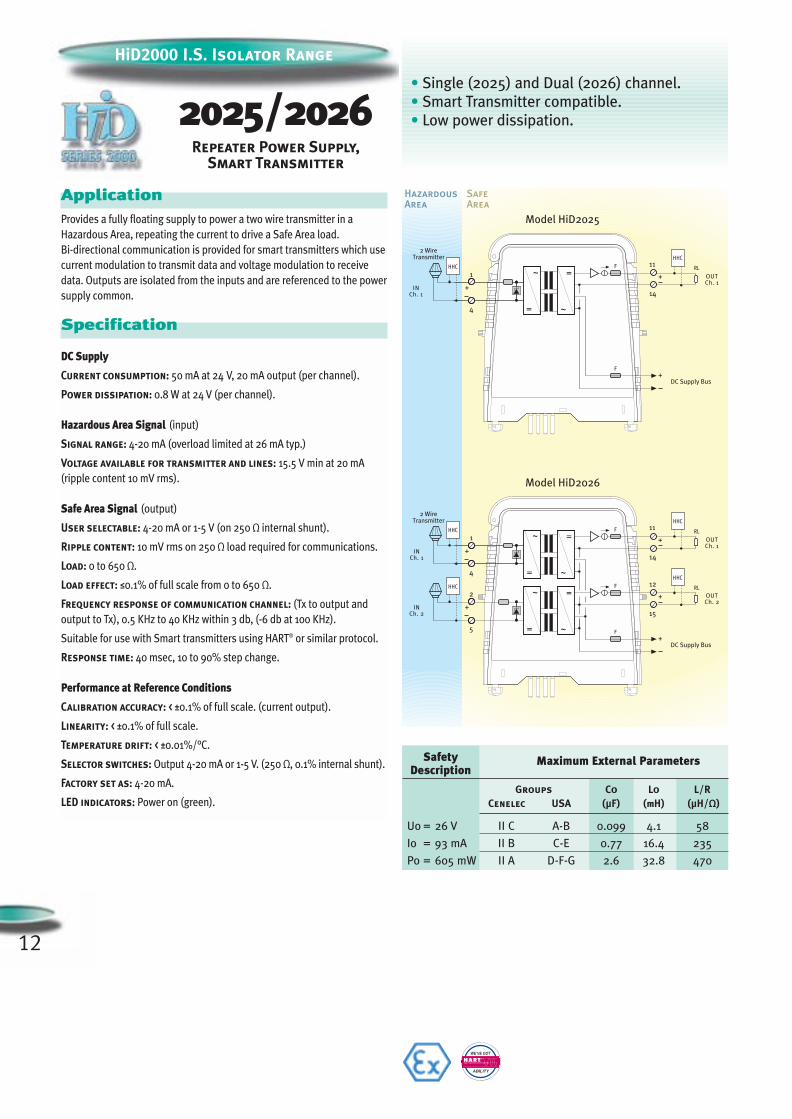
HiD2000 I.S. Isolator Range
2025/2026Repeater Power Supply,
Smart Transmitter
ApplicationProvides a fully floating supply to power a two wire transmitter in a
Hazardous Area, repeating the current to drive a Safe Area load.
Bi-directional communication is provided for smart transmitters which use
current modulation to transmit data and voltage modulation to receive
data. Outputs are isolated from the inputs and are referenced to the power
supply common.
Specification
DC Supply
Current consumption: 50 mA at 24 V, 20 mA output (per channel).
Power dissipation: 0.8 W at 24 V (per channel).
Hazardous Area Signal (input)
Signal range: 4-20 mA (overload limited at 26 mA typ.)
Voltage available for transmitter and lines: 15.5 V min at 20 mA
(ripple content 10 mV rms).
Safe Area Signal (output)
User selectable: 4-20 mA or 1-5 V (on 250 Ω internal shunt).
Ripple content: 10 mV rms on 250 Ω load required for communications.
Load: 0 to 650 Ω.
Load effect: ≤0.1% of full scale from 0 to 650 Ω.
Frequency response of communication channel: (Tx to output and
output to Tx), 0.5 KHz to 40 KHz within 3 db, (-6 db at 100 KHz).
Suitable for use with Smart transmitters using HART® or similar protocol.
Response time: 40 msec, 10 to 90% step change.
Performance at Reference Conditions
Calibration accuracy: < ±0.1% of full scale. (current output).
Linearity: < ±0.1% of full scale.
Temperature drift: < ±0.01%/°C.
Selector switches: Output 4-20 mA or 1-5 V. (250 Ω, 0.1% internal shunt).
Factory set as: 4-20 mA.
LED indicators: Power on (green).
WE’VE GOT
ABILITY
FIELD COMMUNICATIONS PROTOCOL
• Single (2025) and Dual (2026) channel.
• Smart Transmitter compatible.
• Low power dissipation.
SafetyDescription
Maximum External Parameters
Groups Co Lo L/RCenelec USA (µF) (mmH) (µH/Ω)
Uo = 26 V II C A-B 0.099 4.1 58
Io = 93 mA II B C-E 0.77 16.4 235
Po = 605 mW II A D-F-G 2.6 32.8 470
12
13
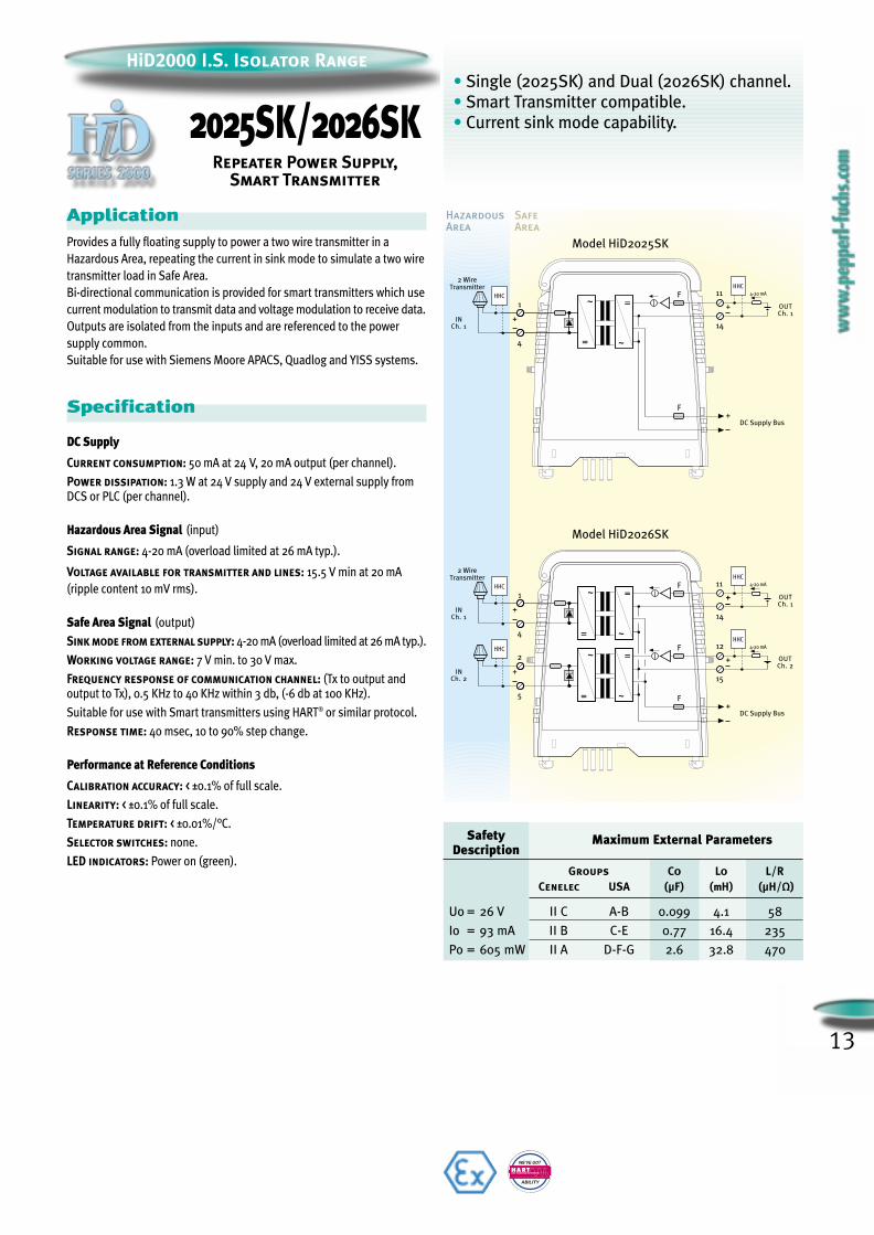
HiD2000 I.S. Isolator Range
2025SK/2026SKRepeater Power Supply,
Smart Transmitter
• Single (2025SK) and Dual (2026SK) channel.
• Smart Transmitter compatible.
• Current sink mode capability.
HazardousArea
SafeArea
Model HiD2025SK
INCh. 1
OUTCh. 1
HHC
F
11F=
~=
~
+
1
4
14
+
HHC4-20 mA
+DC Supply Bus
Model HiD2026SK
~
=
INCh. 1
INCh. 2
OUTCh. 2
OUTCh. 1
11
14
+
HHC4-20 mAHHC
F
F=
~
2
5
+
12F=
~
~
=
HHC
+
1
4
15
+
+
+DC Supply Bus
HHC4-20 mA
~
2 WireTransmitter
2 WireTransmitter
ApplicationProvides a fully floating supply to power a two wire transmitter in a
Hazardous Area, repeating the current in sink mode to simulate a two wire
transmitter load in Safe Area.
Bi-directional communication is provided for smart transmitters which use
current modulation to transmit data and voltage modulation to receive data.
Outputs are isolated from the inputs and are referenced to the power
supply common.
Suitable for use with Siemens Moore APACS, Quadlog and YISS systems.
Specification
DC Supply
Current consumption: 50 mA at 24 V, 20 mA output (per channel).
Power dissipation: 1.3 W at 24 V supply and 24 V external supply fromDCS or PLC (per channel).
Hazardous Area Signal (input)
Signal range: 4-20 mA (overload limited at 26 mA typ.).
Voltage available for transmitter and lines: 15.5 V min at 20 mA
(ripple content 10 mV rms).
Safe Area Signal (output)
Sink mode from external supply: 4-20 mA (overload limited at 26 mA typ.).
Working voltage range: 7 V min. to 30 V max.
Frequency response of communication channel: (Tx to output andoutput to Tx), 0.5 KHz to 40 KHz within 3 db, (-6 db at 100 KHz).
Suitable for use with Smart transmitters using HART® or similar protocol.
Response time: 40 msec, 10 to 90% step change.
Performance at Reference Conditions
Calibration accuracy: < ±0.1% of full scale.
Linearity: < ±0.1% of full scale.
Temperature drift: < ±0.01%/°C.
Selector switches: none.
LED indicators: Power on (green).
WE’VE GOT
ABILITY
FIELD COMMUNICATIONS PROTOCOL
SafetyDescription
Maximum External Parameters
Groups Co Lo L/RCenelec USA (µF) (mmH) (µH/Ω)
Uo = 26 V II C A-B 0.099 4.1 58
Io = 93 mA II B C-E 0.77 16.4 235
Po = 605 mW II A D-F-G 2.6 32.8 470
14
HazardousArea
SafeArea
mA
OUTCh. 1
Model HiD2029
INCh. 1
HHC
F
11F
~
=
14
+
RL
+DC Supply Bus
=
~
=
~
Fault Bus
HHC
+
1
4
7+
mA
mA
INCh. 1
INCh. 2
HHC
2
5+
HHC
+
1
4
7+
6+
OUTCh. 1
OUTCh. 2
Model HiD2030
F
11F
~
=
12F
~
=
14
15
HHC
+
+
HHC
RL
RL
+DC Supply Bus
=
~
=
~
=
~
=
~Fault Bus
Transmitter
Transmitter
INCh. 1
HHC
2
5
+
+
1
4
7+
6
~
=
~
=
Transmitter
Model HiD2030 wired as signal splitter
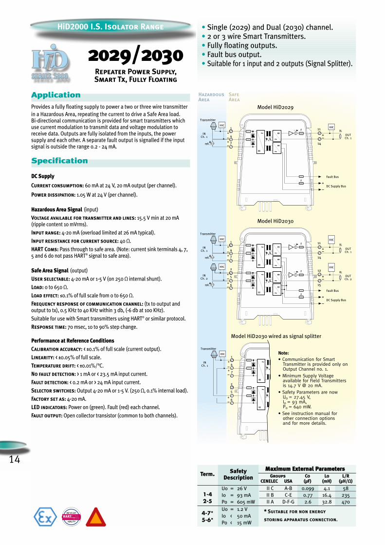
• Communication for SmartTransmitter is provided only onOutput Channel no. 1.
• Minimum Supply Voltageavailable for Field Transmittersis 14.7 V @ 20 mA.
• Safety Parameters are nowU0 = 27.45 V,I0 = 93 mA,P0 = 640 mW.
• See instruction manual forother connection optionsand for more details.
Note:
HiD2000 I.S. Isolator Range
2029/2030Repeater Power Supply,Smart Tx, Fully Floating
• Single (2029) and Dual (2030) channel.
• 2 or 3 wire Smart Transmitters.
• Fully floating outputs.
• Fault bus output.
• Suitable for 1 input and 2 outputs (Signal Splitter).
ApplicationProvides a fully floating supply to power a two or three wire transmitter
in a Hazardous Area, repeating the current to drive a Safe Area load. Bi-directional communication is provided for smart transmitters whichuse current modulation to transmit data and voltage modulation toreceive data. Outputs are fully isolated from the inputs, the powersupply and each other. A separate fault output is signalled if the inputsignal is outside the range 0.2 - 24 mA.
Specification
DC Supply
Current consumption: 60 mA at 24 V, 20 mA output (per channel).
Power dissipation: 1.05 W at 24 V (per channel).
Hazardous Area Signal (input)
Voltage available for transmitter and lines: 15.5 V min at 20 mA(ripple content 10 mVrms).
Input range: 4-20 mA (overload limited at 26 mA typical).
Input resistance for current source: 40 Ω.
HART Coms: Pass through to safe area. (Note: current sink terminals 4, 7,5 and 6 do not pass HART® signal to safe area).
Safe Area Signal (output)
User selectable: 4-20 mA or 1-5 V (on 250 Ω internal shunt).
Load: 0 to 650 Ω.
Load effect: ≤0.1% of full scale from 0 to 650 Ω.
Frequency response of communication channel: (tx to output andoutput to tx), 0.5 KHz to 40 KHz within 3 db, (-6 db at 100 KHz).
Suitable for use with Smart transmitters using HART® or similar protocol.
Response time: 70 msec, 10 to 90% step change.
Performance at Reference ConditionsCalibration accuracy: < ±0.1% of full scale (current output).
Linearity: < ±0.05% of full scale.
Temperature drift: < ±0.01%/°C.
No fault detection: > 1 mA or < 23.5 mA input current.
Fault detection: < 0.2 mA or > 24 mA input current.
Selector switches: Output 4-20 mA or 1-5 V. (250 Ω, 0.1% internal load).
Factory set as: 4-20 mA.
LED indicators: Power on (green). Fault (red) each channel.
Fault output: Open collector transistor (common to both channels).
WE’VE GOT
ABILITY
FIELD COMMUNICATIONS PROTOCOL
Term.
1-42-5
4-7*5-6*
SafetyDescription
Uo = 26 V
Io = 93 mA
Po = 605 mW
Uo = 1.2 V
Io < 50 mA
Po < 15 mW
** Suitable for non energy
storing apparatus connection.
MMaaxxiimmuumm EExxtteerrnnaall PPaarraammeetteerrssGGrroouuppss CCoo LLoo LL//RR
CCEENNEELLEECC UUSSAA ((µµFF)) ((mmHH)) ((µµHH//ΩΩ))
II C A-B 0.099 4.1 58
II B C-E 0.77 16.4 235
II A D-F-G 2.6 32.8 470
15
HiD2000 I.S. Isolator Range
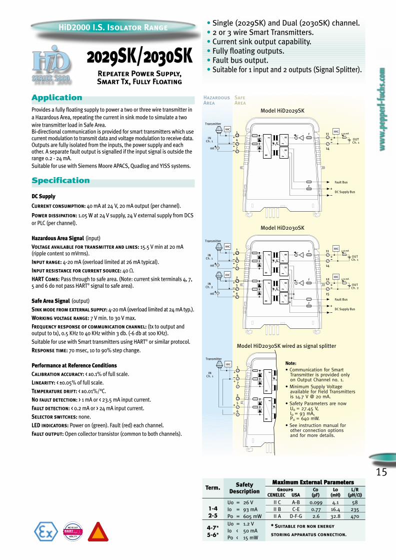
2029SK/2030SKRepeater Power Supply,Smart Tx, Fully Floating
• Single (2029SK) and Dual (2030SK) channel.
• 2 or 3 wire Smart Transmitters.
• Current sink output capability.
• Fully floating outputs.
• Fault bus output.
• Suitable for 1 input and 2 outputs (Signal Splitter).
HazardousArea
SafeArea
mA
INCh. 1
Model HiD2029SK
~
=
OUTCh. 1
+
4-20 mA11
14
HHC
F
F+
1
4
+DC Supply Bus
=
~
=
~
Fault Bus
7+
HHC
mA
mA
HHC
INCh. 1
INCh. 2
Model HiD2030SK
=
~
OUTCh. 2
+
4-20 mA12
15
OUTCh. 1
+
4-20 mA11
14
HHC
F
F
~
=2
5
F
~
=
HHC
+
1
4
+DC Supply Bus
=
~
=
~
=
~
Fault Bus
7+
6+
HHC
+
Transmitter
Transmitter
INCh. 1
HHC
2
5+
+
1
4
7+
6
~
=
~
=
Transmitter
Model HiD2030SK wired as signal splitter
• Communication for SmartTransmitter is provided onlyon Output Channel no. 1.
• Minimum Supply Voltageavailable for Field Transmittersis 14.7 V @ 20 mA.
• Safety Parameters are nowU0 = 27.45 V,I0 = 93 mA,P0 = 640 mW.
• See instruction manual forother connection optionsand for more details.
Note:
ApplicationProvides a fully floating supply to power a two or three wire transmitter in
a Hazardous Area, repeating the current in sink mode to simulate a two
wire transmitter load in Safe Area. Bi-directional communication is provided for smart transmitters which usecurrent modulation to transmit data and voltage modulation to receive data.Outputs are fully isolated from the inputs, the power supply and eachother. A separate fault output is signalled if the input signal is outside therange 0.2 - 24 mA.
Suitable for use with Siemens Moore APACS, Quadlog and YISS systems.
Specification
DC Supply
Current consumption: 40 mA at 24 V, 20 mA output (per channel).
Power dissipation: 1.05 W at 24 V supply, 24 V external supply from DCS
or PLC (per channel).
Hazardous Area Signal (input)
Voltage available for transmitter and lines: 15.5 V min at 20 mA(ripple content 10 mVrms).
Input range: 4-20 mA (overload limited at 26 mA typical).
Input resistance for current source: 40 Ω.
HART Coms: Pass through to safe area. (Note: current sink terminals 4, 7,5 and 6 do not pass HART® signal to safe area).
Safe Area Signal (output)
Sink mode from external supply: 4-20 mA (overload limited at 24 mA typ.).
Working voltage range: 7 V min. to 30 V max.
Frequency response of communication channel: (tx to output andoutput to tx), 0.5 KHz to 40 KHz within 3 db. (-6 db at 100 KHz).
Suitable for use with Smart transmitters using HART® or similar protocol.
Response time: 70 msec, 10 to 90% step change.
Performance at Reference ConditionsCalibration accuracy: < ±0.1% of full scale.
Linearity: < ±0.05% of full scale.
Temperature drift: < ±0.01%/°C.
No fault detection: > 1 mA or < 23.5 mA input current.
Fault detection: < 0.2 mA or > 24 mA input current.
Selector switches: none.
LED indicators: Power on (green). Fault (red) each channel.
Fault output: Open collector transistor (common to both channels).
WE’VE GOT
ABILITY
FIELD COMMUNICATIONS PROTOCOL
Term.
1-42-5
4-7*5-6*
SafetyDescription
Uo = 26 V
Io = 93 mA
Po = 605 mW
Uo = 1.2 V
Io < 50 mA
Po < 15 mW
MMaaxxiimmuumm EExxtteerrnnaall PPaarraammeetteerrssGGrroouuppss CCoo LLoo LL//RR
CCEENNEELLEECC UUSSAA ((µµFF)) ((mmHH)) ((µµHH//ΩΩ))
II C A-B 0.099 4.1 58
II B C-E 0.77 16.4 235
II A D-F-G 2.6 32.8 470
** Suitable for non energy
storing apparatus connection.
HazardousArea
SafeArea
Model HiD2031
DC Supply Bus
+
INCh. 1
14
11
4-20mA
F
OUTCh. 1
+ 1
4
I
P
I
F
~
=
=
~
=
~
+
Model HiD2032
+
INCh. 1
14
11
4-20mA
F
~
=
=
~
=
~
DC Supply Bus+
OUTCh. 1
+ 1
4
I
P
I
+
INCh. 2
15
12
4-20mA
F
~
=
=
~
=
~
OUTCh. 2
+ 2
5
I
P
I
F
HiD2000 I.S. Isolator Range
2031/2032I/P Driver,
Bus Powered
16
• Single (2031) and Dual (2032) channel.
• Bus powered 750 Ω load.
• Fully floating operation.
• Suitable for 1 input and 2 outputs.(see Instruction Manual for details)
ApplicationRepeats a 4-20 mA input signal from a control system to drive I/P
converters, valve actuators and displays located in a Hazardous Area.
Each isolated channel has a low input impedance and allows complete
freedom of connection in the input loop due to the high common mode
compliance with respect to the supply.A field open circuit presents a high impedance to the control device inputto allow alarm conditions to be monitored by control systems.
Specification
DC Supply
Current consumption: 35 mA at 24 V, 20 mA output (per channel).
Power dissipation: 0.75 W at 24 V (per channel).
Hazardous Area Signal (output)
Output: 4-20 mA on a load of 0 to 750 Ω max.
Load effect: ≤0.1% of full scale from 0 to 750 Ω.
Output ripple: 15 mV rms.
Response time: 50 msec, 10 to 90% step change.
Safe Area Signal (input)
Input current: 4-20 mA (reverse polarity protected).
Input drop-out < 4 V with field wiring intact.Input current < 1.2 mA with field wiring open.
Performance at Reference ConditionsCalibration accuracy: < ±0.1% of full scale.
Linearity: < ±0.1% of full scale.
Temperature drift: < ±0.01%/°C.
Selector switches: none.
LED indicators: power ON (green).
SafetyDescription
Maximum External Parameters
GGrroouuppss CCoo LLoo LL//RRCCeenneelleecc UUSSAA ((µµFF)) ((mmHH)) ((µµHH//ΩΩ))
Uo = 26 V II C A-B 0.099 4.1 58
Io = 93 mA II B C-E 0.77 16.4 235
Po = 605 mW II A D-F-G 2.6 32.8 470
17
HiD2000 I.S. Isolator Range
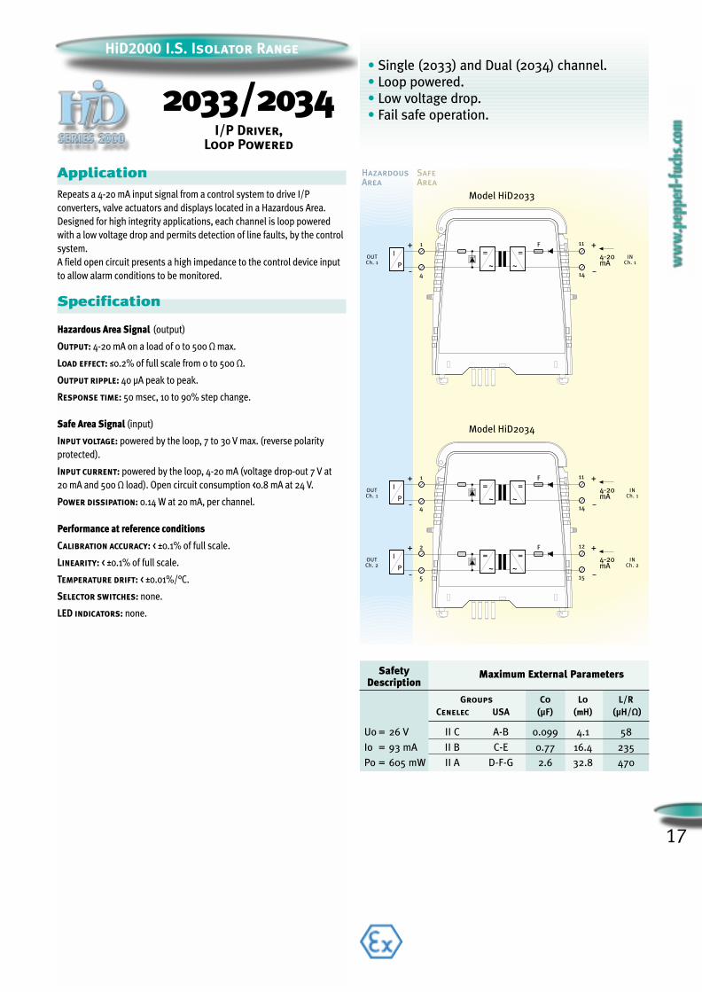
2033/2034I/P Driver,
Loop Powered
• Single (2033) and Dual (2034) channel.
• Loop powered.
• Low voltage drop.
• Fail safe operation.
HazardousArea
SafeArea
=+
Model HiD2033
OUTCh. 1
INCh. 1
+ 1
4 14
11
4-20mA~
F
=
~
I
P
I
Model HiD2034
=+
OUTCh. 1
INCh. 1
+ 1
4 14
11
4-20mA~
F
=
~
I
P
I
=+
OUTCh. 2
INCh. 2
+ 2
5 15
12
4-20mA~
F
=
~
I
P
I
ApplicationRepeats a 4-20 mA input signal from a control system to drive I/P
converters, valve actuators and displays located in a Hazardous Area.
Designed for high integrity applications, each channel is loop powered
with a low voltage drop and permits detection of line faults, by the control
system.
A field open circuit presents a high impedance to the control device input
to allow alarm conditions to be monitored.
Specification
Hazardous Area Signal (output)
Output: 4-20 mA on a load of 0 to 500 Ω max.
Load effect: ≤0.2% of full scale from 0 to 500 Ω.
Output ripple: 40 µA peak to peak.
Response time: 50 msec, 10 to 90% step change.
Safe Area Signal (input)
Input voltage: powered by the loop, 7 to 30 V max. (reverse polarity
protected).
Input current: powered by the loop, 4-20 mA (voltage drop-out 7 V at
20 mA and 500 Ω load). Open circuit consumption <0.8 mA at 24 V.
Power dissipation: 0.14 W at 20 mA, per channel.
Performance at reference conditions
Calibration accuracy: < ±0.1% of full scale.
Linearity: < ±0.1% of full scale.
Temperature drift: < ±0.01%/°C.
Selector switches: none.
LED indicators: none.
SafetyDescription
Maximum External Parameters
Groups Co Lo L/RCenelec USA (µF) (mmH) (µH/Ω)
Uo = 26 V II C A-B 0.099 4.1 58
Io = 93 mA II B C-E 0.77 16.4 235
Po = 605 mW II A D-F-G 2.6 32.8 470

• Single (2035) and Dual (2036) channel.
• Wide operating current range (1.5 to 50 mA).
• Applicable also for loop powered analog output (I/P).
• High accuracy (±0.1%) in I/P applications.
HazardousArea
SafeArea
Model HiD2035
=
OUTCh. 1
Ch. 1
+ 1
4 14
11
~
F
=
~
FIREDETECTORS
+VIN
SHUNT
Model HiD2036
=
OUTCh. 1
Ch. 1
+1
414
11
~
F
=
~
FIREDETECTORS
+VIN
SHUNT
=
OUTCh. 2
Ch. 2
+2
515
12
~
F
=
~
FIREDETECTORS
+VIN
SHUNT
ApplicationThese loop-powered isolators are primarily intended to interface with fire
and smoke detectors, or with similar switched resistor systems requiring a
wide output current range (1.5 to 50 mA) to operate correctly. They can
also be used to drive a current to pressure (I/P) converter or in similar
application requiring an analog output signal.
Specification
Hazardous Area Signal (output)
Fire and Smoke Detectors
Output: 1.5 - 50 mA.
Output characteristic (typical):
Vout = (Vin - 1.6) - (0.4 x Iout) 6 V < Vin < 25 V.
Vout = (25 - 1.6) - (0.4 x Iout) 25 V < Vin < 30 V.
Analog Output I/P Applications
Output: 4-20 mA (on a load of 0 to 750 Ω max.).
Load effect: ≤ 0.3% (of full scale from 0 to 750 Ω).
Output ripple: 150 µA peak to peak.
Safe Area Signal (input)
Operating voltage range: 6-30 V (powered by the loop, reverse polarity protected).
Input current: 1.5 - 50 mA (powered by the loop).
Voltage drop-out: 9.6 V @ 20 mA and 500 Ω load (4 V @ 4 mA).
Open circuit consumption: < 0.6 mA @ 24 V.
Performance at reference conditions
Current transfer error: < ±300 µA,
6 V < Vin < 25 V / 1.5 mA < Iout < 50 mA.
Calibration accuracy: < ±0.1% of full scale (4-20 mA range).
Linearity: < ±0.1% of full scale (4-20 mA range).
Response time: 50 msec. (10 to 90% step change).
Power dissipation: < 0.7 W @ 40 mA, 24 V (per channel).
Temperature drift: < ±0.01%/°C.
Selector switches: none.
LED indicators: none.
HiD2000 I.S. Isolator Range
2035/2036Loop Powered Isolator forFire and Smoke Detectors
18
SafetyDescription
Maximum External Parameters
GGrroouuppss CCoo LLoo LL//RRCCeenneelleecc UUSSAA ((µµFF)) ((mmHH)) ((µµHH//ΩΩ))
Uo = 26 V II C A-B 0.099 4.1 58
Io = 93 mA II B C-E 0.77 16.4 235
Po = 605 mW II A D-F-G 2.6 32.8 470
19
HiD2000 I.S. Isolator Range
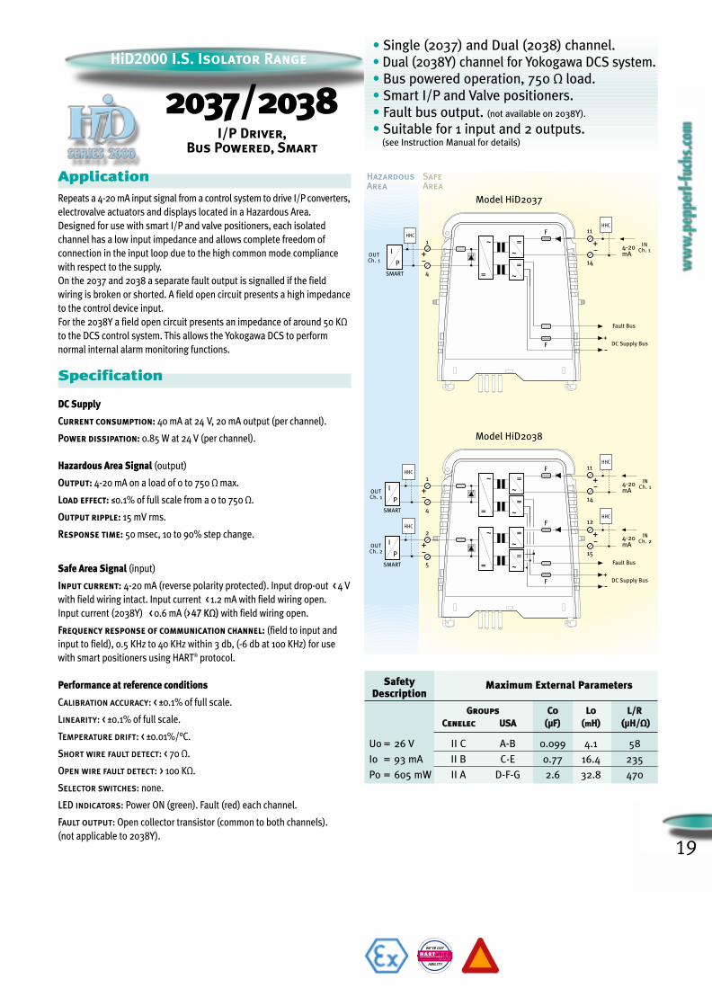
2037/2038I/P Driver,
Bus Powered, Smart
• Single (2037) and Dual (2038) channel.
• Dual (2038Y) channel for Yokogawa DCS system.
• Bus powered operation, 750 Ω load.
• Smart I/P and Valve positioners.
• Fault bus output. (not available on 2038Y).
• Suitable for 1 input and 2 outputs.(see Instruction Manual for details)
HazardousArea
SafeArea
Model HiD2037
Fault Bus
DC Supply Bus
SMART
INCh. 1
14
11F
OUTCh. 1
+
1
4
I
P
I
HHC
+
HHC
4-20mA
F
~
=
=
~
=
~
+
Model HiD2038
Fault Bus
SMART
SMART
INCh. 1
14
11F
~
=
=
~
=
~
DC Supply Bus+
OUTCh. 1
+
1
4
I
P
I
INCh. 2
15
12F
~
=
=
~
=
~
OUTCh. 2
+
2
5
I
P
I
HHC
HHC
+
+
HHC
HHC
4-20mA
4-20mA
F
ApplicationRepeats a 4-20 mA input signal from a control system to drive I/P converters,
electrovalve actuators and displays located in a Hazardous Area.
Designed for use with smart I/P and valve positioners, each isolated
channel has a low input impedance and allows complete freedom of
connection in the input loop due to the high common mode compliance
with respect to the supply.
On the 2037 and 2038 a separate fault output is signalled if the field
wiring is broken or shorted. A field open circuit presents a high impedance
to the control device input.
For the 2038Y a field open circuit presents an impedance of around 50 KΩ
to the DCS control system. This allows the Yokogawa DCS to perform
normal internal alarm monitoring functions.
Specification
DC Supply
Current consumption: 40 mA at 24 V, 20 mA output (per channel).
Power dissipation: 0.85 W at 24 V (per channel).
Hazardous Area Signal (output)
Output: 4-20 mA on a load of 0 to 750 Ω max.
Load effect: ≤0.1% of full scale from a 0 to 750 Ω.
Output ripple: 15 mV rms.
Response time: 50 msec, 10 to 90% step change.
Safe Area Signal (input)
Input current: 4-20 mA (reverse polarity protected). Input drop-out < 4 V
with field wiring intact. Input current < 1.2 mA with field wiring open.
Input current (2038Y) < 0.6 mA (>47 KΩ) with field wiring open.
Frequency response of communication channel: (field to input and
input to field), 0.5 KHz to 40 KHz within 3 db, (-6 db at 100 KHz) for use
with smart positioners using HART® protocol.
Performance at reference conditions
Calibration accuracy: < ±0.1% of full scale.
Linearity: < ±0.1% of full scale.
Temperature drift: < ±0.01%/°C.
Short wire fault detect: < 70 Ω.
Open wire fault detect: > 100 KΩ.
Selector switches: none.
LED indicators: Power ON (green). Fault (red) each channel.
Fault output: Open collector transistor (common to both channels).
(not applicable to 2038Y).
WE’VE GOT
ABILITY
FIELD COMMUNICATIONS PROTOCOL
SafetyDescription
Maximum External Parameters
GGrroouuppss CCoo LLoo LL//RRCCeenneelleecc UUSSAA ((µµFF)) ((mmHH)) ((µµHH//ΩΩ))
Uo = 26 V II C A-B 0.099 4.1 58
Io = 93 mA II B C-E 0.77 16.4 235
Po = 605 mW II A D-F-G 2.6 32.8 470

20
HiD2000 I.S. Isolator Range
2061/2062Temperature Converter,
mV/TC
• Single (2061) and Dual (2062) channel.
• Configurable for thermocouples or mV inputs.
• Simple span and zero selection.
• Output proportional to mV input.
HazardousArea
SafeArea
Model HiD2061
INCh. 1
OUTCh. 1
F
11F
=
~
~
+
1
14
+
RL
+DC Supply Bus
7
4
8
TC
+
CJC
mV/ TC B
Model HiD2062
INCh. 1
INCh. 2
OUTCh. 1
OUTCh. 2
F
11F
=
~~
12F
=
~
+
1
14
15
+
+
RL
RL
+DC Supply Bus
7
4
8
TC
+
CJC
mV/ TC B~
+
2
5
3
6
+
TC
CJC
mV/ TC B
ApplicationAccepts thermocouple or mV input signals from a Hazardous Area and
converts them to an isolated analogue current signal in the Safe Area.
Each channel is fully independant, Input type, range and error handling
parameters are configurable by switches and trimmers.
Each module is supplied with a CJC (Cold Junction Compensator), which is
mounted on the screw terminals (HAT).
Outputs are isolated from input and referenced to the power supply
common.
Specification
DC Supply
Current consumption: 30 mA at 24 V, 20 mA output (per channel).
Power dissipation: 0.6 W at 24 V (per channel).
Hazardous Area Signal (input)
User selectable input: mV–TC type B, E, J, K, N, R, S, T to IEC584-1 and
L to GOST.
Range: -10 mV to + 100 mV.
Span limits: 2.6 mV min, 100 mV max.
Zero suppression: ±500% of span.
Safe Area Signal (output)
User selectable: 4-20 mA or 1-5 V (on 250 Ω internal shunt).
Ripple content: 10 mVrms.
Load: 0 to 650 Ω.
Load effect: ≤0.1% of full scale from 0 to 650 Ω.
Burnout
User programmable: upscale, downscale (burnout current 25 nA).
Performance at reference conditions
Calibration accuracy: < ±0.1% of full scale (current output).
Linearity: < ±0.1% of full scale (terminal based mV
in to mA out for TC).
Temperature influence:< ±0.01%/ °C on zero and span.
Compensation error: ±0.5 °C ±0.05 °C/ (°C deviation from reference
temperature for TC).
Selector switches: Output 4-20 mA or 1-5 V, (250 Ω, 0.1% internal load).
Thermocouple type. Burnout up/down. Input zero and span coarse
settings.
Factory set as: 4-20 mA. TC type K. 0-500 °C, up scale burn-out.
Front panel adjustment: Zero and span trimmers for each channel.
LED indicators: Power ON (green).
SafetyDescription
Maximum External Parameters
GGrroouuppss CCoo LLoo LL//RRCCeenneelleecc UUSSAA ((µµFF)) ((mmHH)) ((µµHH//ΩΩ))
Uo = 13.2 V II C A-B 0.94 88 533
Io = 20 mA II B C-E 5.8 352 2133
Po = 66 mW II A D-F-G 21 704 4267

21
HiD2000 I.S. Isolator Range
HazardousArea
SafeArea
Model HiD2071
POTRTD4W
RTD3W
INCh. 1
OUTCh. 1
F
11F
=
~
~
7
14
+
RL
+DC Supply Bus
1
4
8
Model HiD2072
POTRTD4W
RTD3W
INCh. 1
OUTCh. 1
OUTCh. 2
INCh. 2
F
11F
=
~~
12F
=
~
7
14
15
+
+
RL
RL
+DC Supply Bus
1
4
8
~
3
2
5
6
ApplicationAccepts input from Resistance Temperature Detectors (RTD) or Transmitting
Potentiometers from a Hazardous Area and converts them to an isolated
analog current signal in the Safe Area.
Each channel is fully independant, Input type, range and error handling
parameters are configurable by switches and trimmers.
Outputs are isolated from inputs and referenced to the power supply
common.
Specification
DC Supply
Current consumption: 30 mA at 24 V, 20 mA output (per channel).
Power dissipation: 0.6 W at 24 V (per channel).
Hazardous Area Signal (input)
User selectable
RTD: 2, 3 or 4 wire Pt 100 to DIN 43760.
Measuring current: 0.4 mA max.
Range: -200 °C to 850 °C.
Span limits: 40 °C min, 850 °C max.
Zero suppression ±500% of span.
Pot.: Range: 100 Ω to 100 KΩ.
Note: when use potentiometer with more than 300 Ω value, a shunt resistor
must be mounted in parallel to the potentiometer on the terminal block.
See the HiD2000 instruction manual IM-R&D-111GB-PN991169 at chapter
10.1.2 for details.
Safe Area Signal (output)
Output is linear with temperature for Pt 100 RTD.
User selectable: 4-20 mA or 1-5 V (on 250 Ω internal shunt).
Ripple content: 10 mVrms.
Load: 0 to 650 Ω.
Load effect: ≤0.1% of full scale from 0 to 650 Ω load change.
Burnout (not available on Pot. and RTD 4 wire).
User programmable: upscale, downscale.
Performance at reference conditions
Calibration accuracy: < ±0.1% of full scale (current output).
Linearity: <±0.1% of full scale (terminal based °C or °F input to mA out for Pt 100).
Temperature influence: < ±0.01%/ °C on zero and span.
Selector switches: Output 4-20 mA or 1-5 V. (250 Ω, 0.1% internal load).
Input type. Burnout up/down. Input zero and span coarse settings.
Factory set as: 4-20 mA. 3 wire RTD. 0-200 °C, upscale burn-out.
Front panel adjustment: Zero and span trimmers for each channel.
LED indicators: Power on (green).
2071/2072RTD/Potentiometer
Converter
• Single (2071) and Dual (2072) channel.
• Configurable for 2, 3 or 4 wire RTD.
• Simple span and zero selection.
• Output proportional to temperature.
• Burnout up or down scale.
SafetyDescription
Maximum External Parameters
GGrroouuppss CCoo LLoo LL//RRCCeenneelleecc UUSSAA ((µµFF)) ((mmHH)) ((µµHH//ΩΩ))
Uo = 13.2 V II C A-B 0.94 88 533
Io = 20 mA II B C-E 5.8 352 2133
Po = 66 mW II A D-F-G 21 704 4267

22
HiD2000 I.S. Isolator Range
2082Temperature Converter,
mV/TC/Pot/RTD
• Dual (2082) channel.
• Configurable for thermocouples or mV inputs,
or potentiometer or 2/3/4 wire RTD input.
• Current output source and sink modes.
• Sensor burnout detection.
• Output proportional to temperature.
• Configured by PACTware™.
HazardousArea
SafeArea
Model HiD2082
5
4
1
2
7
3
6
8
RTD4W
RTD3W
INCh.1
POT RTD2W TC mV
+
CJC
INCh.2
++
11
14
+
SOURCE4-20 mA
1-5 V
+
SINK4-20 mA
OUTCh.1
12
15
+ +OUTCh.2
MICROCONTROLLER
F
F
F+
Fault Bus
DC SupplyBus
ApplicationAccepts thermocouple (TC), millivolt, potentiometer or Resistance
Temperature Detectors (RTD) from a Hazardous Area and converts their
information, with full linearisation, into analogue outputs.
Each channel is fully independant with input type, range and error
handling parameters configurable through the pc interface using
PACTware™.
The mV or TC inputs are fully isolated and the outputs are isolated from
inputs and power supply.
The outputs can be selected as current source, current sink or voltage by
switches.
Specification
DC Supply
Current consumption: 30 mA at 24 V, 20 mA output (per channel).
Power dissipation: 0.6 W at 24 V (per channel).
Hazardous Area Signal (input)
Input type: mV range ± 100 mV.
TC B, E, J, K, N, R, S, T to IEC584-1, L to GOST standard.
RTD connection for 2-3-4 wire;
Pt 100, Pt 50, Pt 10; to IEC751 & GOST,
Cu100, Cu50, Cu10; to GOST,
Ni 100, to DIN43760.
Pot. 100 R to 20 K.
Safe Area Signal (output)
Output: linear with temperature for TC and RTD inputs.
User selectable: 0/4-20 mA source, load 0-550R.
or 4-20 mA sink, working voltage 7 V to 30 V.
or 0/1-5 V (on 250 R internal shunt).
Load effect: ≤0.1% of full scale from 0 to 550 Ω.
Burnout
User programmable: none, upscale, downscale.
Performance at reference conditions
Calibration accuracy: ≤0.1% of full scale (current output).
Linearity: <±0.05% of full scale.
Temperature drift: <±0.01%/ °C, ±0.005%/ °C typical.
Compensation range: -20 to +60 °C.
Compensation error: ±0.5 °C, ±0.05 °C/°C.
General
Selector switches: Output: 4-20 mA current source.
4-20 mA current sink.
1-5 V (250 Ω, 0.1% internal load).
LED indicators: Power ON (green). Fault (red, per channel).
Fault output: Open collector transistor (common to both channels).
SafetyDescription
Maximum External Parameters
GGrroouuppss CCoo LLoo LL//RRCCeenneelleecc UUSSAA ((µµFF)) ((mmHH)) ((µµHH//ΩΩ))
Uo = 10 V II C A-B 3 158 957
Io = 15 mA II B C-E 20.2 632 3828
Po = 38 mW II A D-F-G 100 1260 7656
23
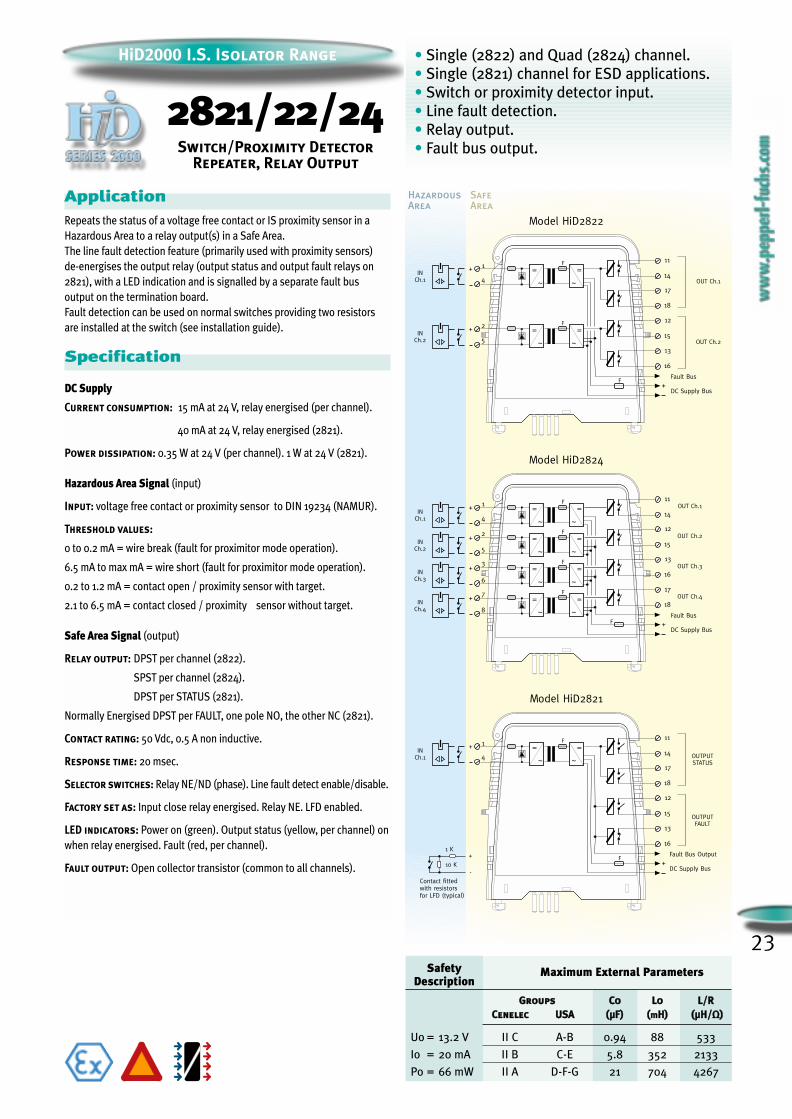
• Single (2822) and Quad (2824) channel.
• Single (2821) channel for ESD applications.
• Switch or proximity detector input.
• Line fault detection.
• Relay output.
• Fault bus output.
HazardousArea
SafeArea
17
18
13
16
11
14INCh.1
1+
OUTPUTFAULT
12
15
OUTPUTSTATUS
=
~
=
~
F
F+
DC Supply Bus
Fault Bus Output
Contact fittedwith resistorsfor LFD (typical)
1 K
10 K
+
-
Model HiD2821
INCh.2
2
5
+
17
18
13
16
OUT Ch.1
11
14INCh.1
1
4
+
OUT Ch.2
Model HiD2822
=
~
=
~
F
12
15=
~
=
~
F
F+
DC Supply Bus
Fault Bus
INCh.2
2
5
+
INCh.3
3
6
+
INCh.4
7
8
+
Model HiD2824
OUT Ch.111
14INCh.1
1+ =
~
=
~
F
OUT Ch.212
15=
~
=
~
F
OUT Ch.313
16=
~
=
~
F
OUT Ch.417
18=
~
=
~
F
F +DC Supply Bus
Fault Bus
4
4
ApplicationRepeats the status of a voltage free contact or IS proximity sensor in a
Hazardous Area to a relay output(s) in a Safe Area.
The line fault detection feature (primarily used with proximity sensors)
de-energises the output relay (output status and output fault relays on
2821), with a LED indication and is signalled by a separate fault bus
output on the termination board.
Fault detection can be used on normal switches providing two resistors
are installed at the switch (see installation guide).
Specification
DC Supply
Current consumption: 15 mA at 24 V, relay energised (per channel).
40 mA at 24 V, relay energised (2821).
Power dissipation: 0.35 W at 24 V (per channel). 1 W at 24 V (2821).
Hazardous Area Signal (input)
Input: voltage free contact or proximity sensor to DIN 19234 (NAMUR).
Threshold values:
0 to 0.2 mA = wire break (fault for proximitor mode operation).
6.5 mA to max mA = wire short (fault for proximitor mode operation).
0.2 to 1.2 mA = contact open / proximity sensor with target.
2.1 to 6.5 mA = contact closed / proximity sensor without target.
Safe Area Signal (output)
Relay output: DPST per channel (2822).
SPST per channel (2824).
DPST per STATUS (2821).
Normally Energised DPST per FAULT, one pole NO, the other NC (2821).
Contact rating: 50 Vdc, 0.5 A non inductive.
Response time: 20 msec.
Selector switches: Relay NE/ND (phase). Line fault detect enable/disable.
Factory set as: Input close relay energised. Relay NE. LFD enabled.
LED indicators: Power on (green). Output status (yellow, per channel) on
when relay energised. Fault (red, per channel).
Fault output: Open collector transistor (common to all channels).
2821/22/24Switch/Proximity Detector
Repeater, Relay Output
SafetyDescription
Maximum External Parameters
GGrroouuppss CCoo LLoo LL//RRCCeenneelleecc UUSSAA ((µµFF)) ((mmHH)) ((µµHH//ΩΩ))
Uo = 13.2 V II C A-B 0.94 88 533
Io = 20 mA II B C-E 5.8 352 2133
Po = 66 mW II A D-F-G 21 704 4267
HiD2000 I.S. Isolator Range
24
HiD2000 I.S. Isolator Range
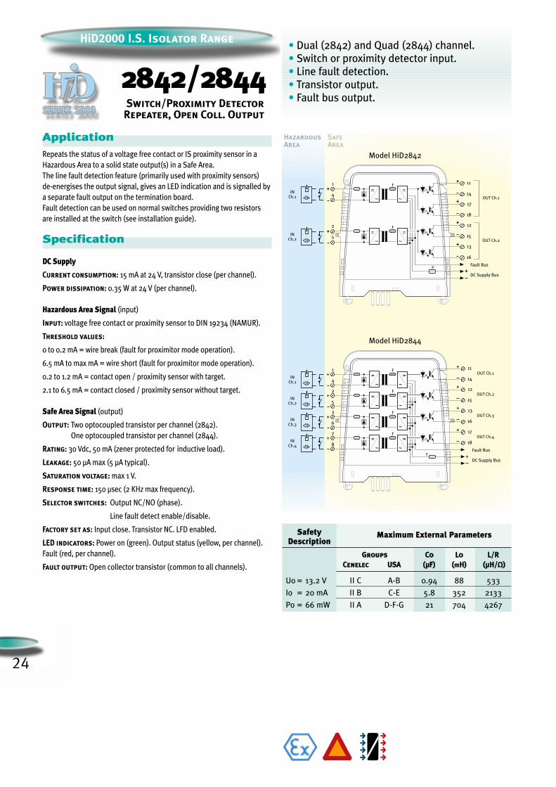
2842/2844Switch/Proximity Detector
Repeater, Open Coll. Output
• Dual (2842) and Quad (2844) channel.
• Switch or proximity detector input.
• Line fault detection.
• Transistor output.
• Fault bus output.
HazardousArea
SafeArea
Model HiD2842
INCh.2
+
17
18
13
16
OUT Ch.1
11
14INCh.1
+
OUT Ch.2
=
~
=
~
F
12
15=
~
=
~
F
F+
DC Supply Bus
Fault Bus
+
+
+
+
INCh.2
2
5
+
INCh.3
3
6
+
INCh.4
7
8
+
Model HiD2844
OUT Ch.111
14INCh.1
1
4
+ =
~
=
~
F
OUT Ch.212
15=
~
=
~
F
OUT Ch.313
16=
~
=
~
F
OUT Ch.417
18=
~
=
~
F
F +DC Supply Bus
Fault Bus
+
+
+
+
2
5
1
4
ApplicationRepeats the status of a voltage free contact or IS proximity sensor in a
Hazardous Area to a solid state output(s) in a Safe Area.
The line fault detection feature (primarily used with proximity sensors)
de-energises the output signal, gives an LED indication and is signalled by
a separate fault output on the termination board.
Fault detection can be used on normal switches providing two resistors
are installed at the switch (see installation guide).
Specification
DC Supply
Current consumption: 15 mA at 24 V, transistor close (per channel).
Power dissipation: 0.35 W at 24 V (per channel).
Hazardous Area Signal (input)
Input: voltage free contact or proximity sensor to DIN 19234 (NAMUR).
Threshold values:
0 to 0.2 mA = wire break (fault for proximitor mode operation).
6.5 mA to max mA = wire short (fault for proximitor mode operation).
0.2 to 1.2 mA = contact open / proximity sensor with target.
2.1 to 6.5 mA = contact closed / proximity sensor without target.
Safe Area Signal (output)
Output: Two optocoupled transistor per channel (2842).
One optocoupled transistor per channel (2844).
Rating: 30 Vdc, 50 mA (zener protected for inductive load).
Leakage: 50 µA max (5 µA typical).
Saturation voltage: max 1 V.
Response time: 150 µsec (2 KHz max frequency).
Selector switches: Output NC/NO (phase).
Line fault detect enable/disable.
Factory set as: Input close. Transistor NC. LFD enabled.
LED indicators: Power on (green). Output status (yellow, per channel).
Fault (red, per channel).
Fault output: Open collector transistor (common to all channels).
SafetyDescription
Maximum External Parameters
GGrroouuppss CCoo LLoo LL//RRCCeenneelleecc UUSSAA ((µµFF)) ((mmHH)) ((µµHH//ΩΩ))
Uo = 13.2 V II C A-B 0.94 88 533
Io = 20 mA II B C-E 5.8 352 2133
Po = 66 mW II A D-F-G 21 704 4267
25
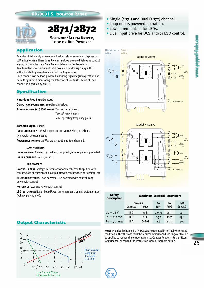
• Single (2871) and Dual (2872) channel.
• Loop or bus powered operation.
• Low current output for LEDs.
• Dual input drive for DCS and/or ESD control.
ApplicationEnergises intrinsically safe solenoid valves, alarm sounders, displays or
LED indicators in a Hazardous Area from a loop powered Safe Area control
signal, or controlled by a Safe Area switch contact or transistor.
An alternative low current output is available for driving a single LED
without installing an external current limiting resistor.
Each channel can be loop-powered, ensuring high integrity operation and
permitting current monitoring for detection of line fault. Status of each
channel is signalled by an LED.
Specification
Hazardous Area Signal (output)
Output characteristic: see diagram below.
Response time (at 300 Ω load): Turn-on time 1 msec.
Turn-off time 8 msec.
Max. operating frequency 50 Hz.
Safe Area Signal (input)
Input current: 20 mA with open output. 70 mA with 300 Ω load.
75 mA with shorted output.
Power dissipation: 1.2 W at 24 V, 300 Ω load (per channel).
Loop powered:
Input voltage: Powered by the loop, 21 - 30 Vdc, reverse polarity protected.
Inrush current: 1A, 0.5 msec.
Bus powered:
Control signal: Voltage free contact or open collector. Output on with
contact close or transistor on. Output off with contact open or transistor off.
Selector switches: Loop powered. Bus powered with control. Loop
power with control.
Factory set as: Bus Power with control.
LED indicators: Bus or Loop Power on (green per channel) output status
(yellow, per channel).
Output Characteristic
SafetyDescription
Maximum External Parameters
GGrroouuppss CCoo LLoo LL//RRCCeenneelleecc UUSSAA ((µµFF)) ((mmHH)) ((µµHH//ΩΩ))
Uo = 26 V II C A-B 0.099 2.9 49
Io = 110 mA II B C-E 0.77 11.7 198
Po = 715 mW II A D-F-G 2.6 23.5 397
2871/2872Solenoid/Alarm Driver,
Loop or Bus Powered
HazardousArea
SafeArea
Model HiD2871
Control
LoopPowered=
=
+ 1
4
~
OUTCh. 1 IN
Ch. 1
~7
18
17
14
11
++
+
F+
DC Supply Bus
Model HiD2872
Control
LoopPowered
Control
LoopPowered
=
=
+ 1
4
~
OUTCh. 1 IN
Ch. 1
~7
18
17
14
11
=
=
+2
5
~
OUTCh. 2 IN
Ch. 2
~6
16
13
15
12
F+
DC Supply Bus
+
+
+
+
+
+
Note: when both channels of HiD2872 are operated in normally energisedcondition, either the load must be reduced or increased spacing/ventilationbe applied to reduce the temperature rise. Contact Pepperl + Fuchs Elconfor guidance, or consult the Instruction Manual for more details.
0
HiD2000 I.S. Isolator Range
26
HiD2000 I.S. Isolator Range
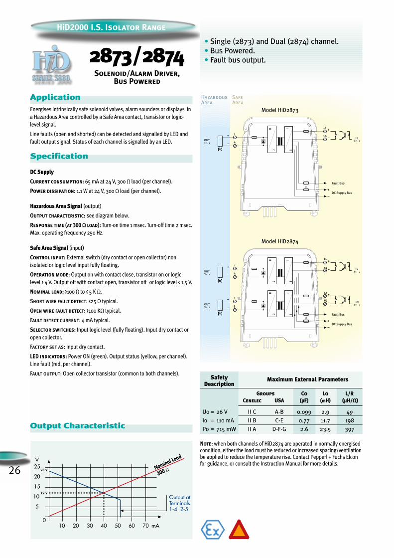
2873/2874Solenoid/Alarm Driver,
Bus Powered
• Single (2873) and Dual (2874) channel.
• Bus Powered.
• Fault bus output.
HazardousArea
SafeArea
Model HiD2873
DC Supply Bus
Fault Bus
=
=
+ 1
4
~
OUTCh. 1
INCh. 1
~
14
11+
F+
Model HiD2874
=
=
+ 1
4
~
OUTCh. 1
INCh. 1
~
14
11
=
=
+ 2
5
~
OUTCh. 2
INCh. 2
~
15
12
+
+
F+
DC Supply Bus
Fault Bus
ApplicationEnergises intrinsically safe solenoid valves, alarm sounders or displays in
a Hazardous Area controlled by a Safe Area contact, transistor or logic-
level signal.
Line faults (open and shorted) can be detected and signalled by LED and
fault output signal. Status of each channel is signalled by an LED.
Specification
DC Supply
Current consumption: 65 mA at 24 V, 300 Ω load (per channel).
Power dissipation: 1.1 W at 24 V, 300 Ω load (per channel).
Hazardous Area Signal (output)
Output characteristic: see diagram below.
Response time (at 300 Ω load): Turn-on time 1 msec. Turn-off time 2 msec.
Max. operating frequency 250 Hz.
Safe Area Signal (input)
Control input: External switch (dry contact or open collector) non
isolated or logic level input fully floating.
Operation mode: Output on with contact close, transistor on or logic
level > 4 V. Output off with contact open, transistor off or logic level < 1.5 V.
Nominal load: >100 Ω to < 5 K Ω.
Short wire fault detect: <25 Ω typical.
Open wire fault detect: >100 KΩ typical.
Fault detect current: 4 mA typical.
Selector switches: Input logic level (fully floating). Input dry contact or
open collector.
Factory set as: Input dry contact.
LED indicators: Power ON (green). Output status (yellow, per channel).
Line fault (red, per channel).
Fault output: Open collector transistor (common to both channels).
Output Characteristic
Note: when both channels of HiD2874 are operated in normally energisedcondition, either the load must be reduced or increased spacing/ventilationbe applied to reduce the temperature rise. Contact Pepperl + Fuchs Elconfor guidance, or consult the Instruction Manual for more details.
SafetyDescription
Maximum External Parameters
GGrroouuppss CCoo LLoo LL//RRCCeenneelleecc UUSSAA ((µµFF)) ((mmHH)) ((µµHH//ΩΩ))
Uo = 26 V II C A-B 0.099 2.9 49
Io = 110 mA II B C-E 0.77 11.7 198
Po = 715 mW II A D-F-G 2.6 23.5 397
27
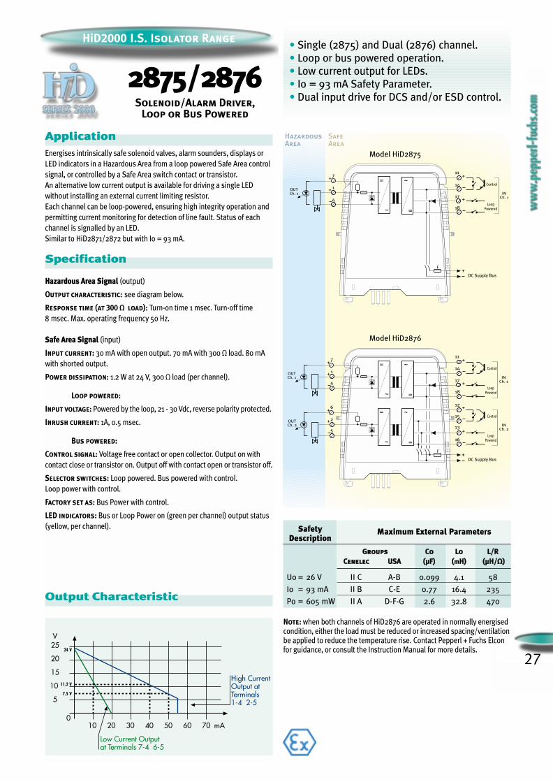
• Single (2875) and Dual (2876) channel.
• Loop or bus powered operation.
• Low current output for LEDs.
• Io = 93 mA Safety Parameter.
• Dual input drive for DCS and/or ESD control.
HazardousArea
SafeArea
Model HiD2875
Control
LoopPowered=
=
+ 1
4
~
OUTCh. 1 IN
Ch. 1
~7
18
17
14
11
++
+
F+
DC Supply Bus
Model HiD2876
Control
LoopPowered
Control
LoopPowered
=
=
+ 1
4
~
OUTCh. 1 IN
Ch. 1
~7
18
17
14
11
=
=
+2
5
~
OUTCh. 2 IN
Ch. 2
~6
16
13
15
12
F+
DC Supply Bus
+
+
+
+
+
+
ApplicationEnergises intrinsically safe solenoid valves, alarm sounders, displays or
LED indicators in a Hazardous Area from a loop powered Safe Area control
signal, or controlled by a Safe Area switch contact or transistor.
An alternative low current output is available for driving a single LED
without installing an external current limiting resistor.
Each channel can be loop-powered, ensuring high integrity operation and
permitting current monitoring for detection of line fault. Status of each
channel is signalled by an LED.
Similar to HiD2871/2872 but with Io = 93 mA.
Specification
Hazardous Area Signal (output)
Output characteristic: see diagram below.
Response time (at 300 Ω load): Turn-on time 1 msec. Turn-off time
8 msec. Max. operating frequency 50 Hz.
Safe Area Signal (input)
Input current: 30 mA with open output. 70 mA with 300 Ω load. 80 mA
with shorted output.
Power dissipation: 1.2 W at 24 V, 300 Ω load (per channel).
Loop powered:
Input voltage: Powered by the loop, 21 - 30 Vdc, reverse polarity protected.
Inrush current: 1A, 0.5 msec.
Bus powered:
Control signal: Voltage free contact or open collector. Output on with
contact close or transistor on. Output off with contact open or transistor off.
Selector switches: Loop powered. Bus powered with control.
Loop power with control.
Factory set as: Bus Power with control.
LED indicators: Bus or Loop Power on (green per channel) output status
(yellow, per channel).
Output Characteristic
HiD2000 I.S. Isolator Range
2875/2876Solenoid/Alarm Driver,
Loop or Bus Powered
Note: when both channels of HiD2876 are operated in normally energisedcondition, either the load must be reduced or increased spacing/ventilationbe applied to reduce the temperature rise. Contact Pepperl + Fuchs Elconfor guidance, or consult the Instruction Manual for more details.
SafetyDescription
Maximum External Parameters
GGrroouuppss CCoo LLoo LL//RRCCeenneelleecc UUSSAA ((µµFF)) ((mmHH)) ((µµHH//ΩΩ))
Uo = 26 V II C A-B 0.099 4.1 58
Io = 93 mA II B C-E 0.77 16.4 235
Po = 605 mW II A D-F-G 2.6 32.8 470

28
HiD2000 I.S. Isolator Range
2877/2878Solenoid/Alarm Driver,
Bus Powered
HazardousArea
SafeArea
Model HiD2877
DC Supply Bus
Fault Bus
=
=
+ 1
4
~
OUTCh. 1
INCh. 1
~
14
11+
F+
Model HiD2878
=
=
+ 1
4
~
OUTCh. 1
INCh. 1
~
14
11
=
=
+ 2
5
~
OUTCh. 2
INCh. 2
~
15
12
+
+
F+
DC Supply Bus
Fault Bus
ApplicationEnergises intrinsically safe solenoid valves, alarm sounders or displays in
a Hazardous Area controlled by a Safe Area contact, transistor or logic-
level signal.
Line faults (open and shorted) can be detected and signalled by LED and
fault output signal. Status of each channel is signalled by an LED.
Similar to HiD2873/2874 but with Io = 93 mA.
Specification
DC Supply
Current consumption: 60 mA at 24 V, 300 Ω load (per channel).
Power dissipation: 1 W at 24 V, 300 Ω load (per channel).
Hazardous Area Signal (output)
Output characteristic: see diagram below.
Response time (at 300 Ω load): Turn-on time 1 msec. Turn-off time
2 msec. Max. operating frequency 250 Hz.
Safe Area Signal (input)
Control input: External switch (dry contact or open collector) non
isolated or logic level input fully floating.
Operation mode: Output on with contact close, transistor on or logic
level > 4 V. Output off with contact open, transistor off or logic level < 1.5 V.
Nominal load: >100 Ω to < 5 K Ω.
Short wire fault detect: < 25 Ω typical.
Open wire fault detect: >100 KΩ typical.
Fault detect current: 4 mA typical.
Selector switches: Input logic level (fully floating). Input dry contact or
open collector.
Factory set as: Input dry contact.
LED indicators: Power ON (green). Output status (yellow, per channel).
Line fault (red, per channel).
Fault output: Open collector transistor (common to both channels).
Output Characteristic
Note: when both channels of HiD2878 are operated in normally energisedcondition, either the load must be reduced or increased spacing/ventilationbe applied to reduce the temperature rise. Contact Pepperl + Fuchs Elconfor guidance, or consult the Instruction Manual for more details.
• Single (2877) and Dual (2878) channel.
• Bus powered.
• Fault bus output.
• Io = 93 mA Safety Parameter.
SafetyDescription
Maximum External Parameters
GGrroouuppss CCoo LLoo LL//RRCCeenneelleecc UUSSAA ((µµFF)) ((mmHH)) ((µµHH//ΩΩ))
Uo = 26 V II C A-B 0.099 4.1 58
Io = 93 mA II B C-E 0.77 16.4 235
Po = 605 mW II A D-F-G 2.6 32.8 470
29
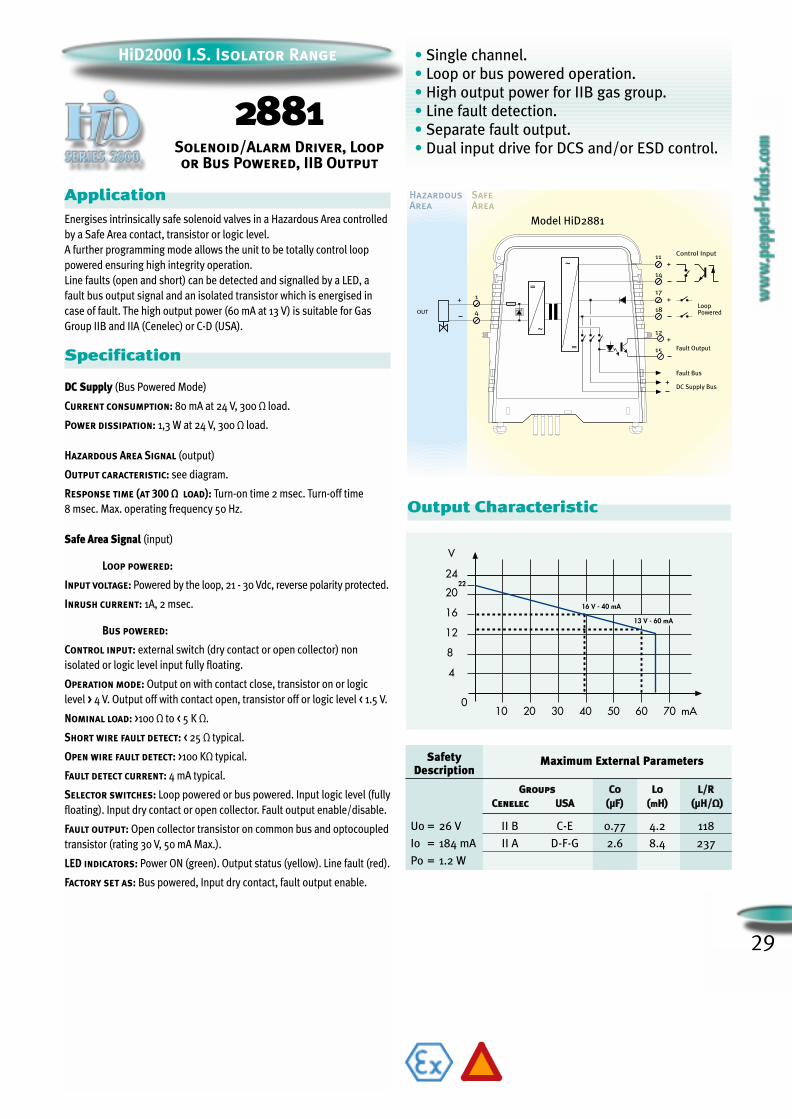
• Single channel.
• Loop or bus powered operation.
• High output power for IIB gas group.
• Line fault detection.
• Separate fault output.
• Dual input drive for DCS and/or ESD control.
HazardousArea
SafeArea
Model HiD2881
+DC Supply Bus
Fault Bus
=
=
+ 1
4
~
OUT
Control Input
~14
11+
15
12
18
17+
+
Fault Output
LoopPowered
ApplicationEnergises intrinsically safe solenoid valves in a Hazardous Area controlled
by a Safe Area contact, transistor or logic level.
A further programming mode allows the unit to be totally control loop
powered ensuring high integrity operation.
Line faults (open and short) can be detected and signalled by a LED, a
fault bus output signal and an isolated transistor which is energised in
case of fault. The high output power (60 mA at 13 V) is suitable for Gas
Group IIB and IIA (Cenelec) or C-D (USA).
Specification
DC Supply (Bus Powered Mode)
Current consumption: 80 mA at 24 V, 300 Ω load.
Power dissipation: 1,3 W at 24 V, 300 Ω load.
Hazardous Area Signal (output)
Output caracteristic: see diagram.
Response time (at 300 Ω load): Turn-on time 2 msec. Turn-off time
8 msec. Max. operating frequency 50 Hz.
Safe Area Signal (input)
Loop powered:
Input voltage: Powered by the loop, 21 - 30 Vdc, reverse polarity protected.
Inrush current: 1A, 2 msec.
Bus powered:
Control input: external switch (dry contact or open collector) non
isolated or logic level input fully floating.
Operation mode: Output on with contact close, transistor on or logic
level > 4 V. Output off with contact open, transistor off or logic level < 1.5 V.
Nominal load: >100 Ω to < 5 K Ω.
Short wire fault detect: < 25 Ω typical.
Open wire fault detect: >100 KΩ typical.
Fault detect current: 4 mA typical.
Selector switches: Loop powered or bus powered. Input logic level (fully
floating). Input dry contact or open collector. Fault output enable/disable.
Fault output: Open collector transistor on common bus and optocoupled
transistor (rating 30 V, 50 mA Max.).
LED indicators: Power ON (green). Output status (yellow). Line fault (red).
Factory set as: Bus powered, Input dry contact, fault output enable.
Output Characteristic
2881Solenoid/Alarm Driver, Loopor Bus Powered, IIB Output
HiD2000 I.S. Isolator Range
SafetyDescription
Maximum External Parameters
GGrroouuppss CCoo LLoo LL//RRCCeenneelleecc UUSSAA ((µµFF)) ((mmHH)) ((µµHH//ΩΩ))
Uo = 26 V II B C-E 0.77 4.2 118
Io = 184 mA II A D-F-G 2.6 8.4 237
Po = 1.2 W

FR-AI-HART-01-RModel2116/HAT
DCS I/O Card Racks
DCS I/O Card Racks
Legend:
Color = 4-20 mA Signal
Color = HART® Signal
PAM Workstation
Field Mounted HARTTransmitters & Valves
RS-485 toRS-232 converter
Field Mounted HARTTransmitters & Valves
MultidropRS-485 network(up to 31 units)
HiD2000 Intrinsic Safety Isolatorwith integral HART Mux
FR-AI-HART-01-RModel2116/HAT
32 Channel
Hart ®
Multiplexer
MU
X
2700
FAU
LTH
AR
T T
X
PW
RO
NP
WR
ON
2026
PW
RO
N
2026
PW
RO
N
2026
PW
RO
N
2026
PW
RO
N
2026
PW
RO
N
2026
PW
RO
N
2026
PW
RO
N
2026
PW
RO
N
2026
PW
RO
N
2026
PW
RO
N
2026
PW
RO
N
2026
PW
RO
N
2026
PW
RO
N
2026
PW
RO
N
2026
PW
RO
N
202632 C
hannelH
art ®M
ultiplexer
MU
X
2700
FAU
LTH
AR
T T
X
PW
RO
NP
WR
ON
2026
PW
RO
N
2026
PW
RO
N
2026
PW
RO
N
2026
PW
RO
N
2026
PW
RO
N
2026
PW
RO
N
2026
PW
RO
N
2026
PW
RO
N
2026
PW
RO
N
2026
PW
RO
N
2026
PW
RO
N
2026
PW
RO
N
2026
PW
RO
N
2026
PW
RO
N
2026
PW
RO
N
2026
HART® Multiplexer
Mux270032 Channel HART® Multiplexer
• 32 channel input.• RS485 serial data connection.• Communicate with HART® Transmitters and
HART® I/P Valve positioners.• No complicated master/slave configuration.• Channel to channel isolation.
ApplicationThe Mux2700 HART® Multiplexer provides 32 signal channels forconnection to “smart” transmitters or control devices supporting digitalcommunication according to the HART® standard. Alternatively up to 16HART® only (i.e. no 4-20mA signal) devices can be connected to eachchannel in multidrop configuration. Full three-port isolation is includedand each input channel has dual capacitor isolation for freedom of loopconnection. It acts as a gateway between a workstation - typically a PCwith suitable PAM software - and the field instrumentation. Each Mux2700is networked simply by connecting the high-speed RS485 output in multi-drop configuration. The Mux2700 interrogates each field device, under thesupervision of the workstation, retrieving information for storage in itsinternal database, which can then be accessed at ease.
Specification
DC Supply
Current consumption: 28 mA at 24 V typical, RS485 quiescent.
Power dissipation: 0.7 W at 24 V.
Signal Channels
Number of channels: 32.
Dc Isolation: dual capacitor each channel.
Common mode voltage: up to 30 V.
Differential mode clamping: ± 5.2 V (for transient or ac signals).
Common mode clamping: ± 10 V (for transient or ac signals).
Receive signal range: 0.12 Vpp < signal < 1.5 Vpp.
Receive impedance: > 5000 ohms.
Carrier detect level: signal > 0.12 Vpp, CD asserted.signal < 0.08 Vpp, CD not asserted.
Transmit amplitude: 200 Ω load - 0.43 Vpp < signal < 0.49 Vpp.500 Ω load - 1.1 Vpp < signal < 1.2 Vpp.
Device type: secondary device.
Impedance level: high impedance device.
Data link type: HART® primary or secondary.
Field multi-drop support: option available upon request .
Note: the Mux 2700 generally complies with the HART® FSK Physical LayerSpecification Rev. 8.0 available from the HART® CommunicationFoundation. HART® is a registered trademark of the HART®
Communication Foundation.
Galvanic Isolation Specifications24 V supply/Field channels: 1400 Vac, rms.
24 V supply /RS-485 serial port: 1400 Vac, rms.
RS-485 serial port/Field channels: 500 Vac, rms.
Serial PortLine type: RS-485, differential pair plus ground.
Line speed: 9600 or 19200 Baud, switch selectable.
Line topology: multi-point, master-slave connection.
Unit address: 1 to 31, switch selectable.
Selector PortSW1-SW5: Unit slave address.
SW6-SW7: Baud rate.
SW8: Test mode.
LED IndicatorsPower ON: green.
HART® transmission: yellow.
Fault: red.
SAFE AREA or HAZARDOUS AREA zone 2 (IEC60079-14)
Model Mux2700
DC Supply Bus+
RS485DataBus
F
Mux.&
HARTModem
Ch. 2
Ch. 1
Ch. 32
RS485I/F
~
=
=
~=
~
WE’VE GOT
ABILITY
FIELD COMMUNICATIONS PROTOCOL
30
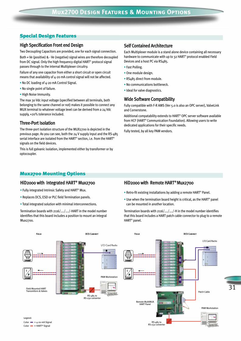
Mux2700 Design Features & Mounting Options
Special Design Features
HHiigghh SSppeecciiffiiccaattiioonn FFrroonntt eenndd DDeessiiggnn Two Decoupling Capacitors are provided, one for each signal connection.
Both + Ve (positive) & - Ve (negative) signal wires are therefore decoupledfrom DC signal. Only the high frequency digital HART® protocol signalpasses through to the internal Multiplexer circuitry.
Failure of any one capacitor from either a short circuit or open circuitmeans that availability of 4-20 mA control signal will not be affected.
• No DC loading of 4-20 mA Control Signal.
• No single point of failure.
• High Noise Immunity.
The max 30 Vdc input voltage (specified between all terminals, bothbelonging to the same channel or not) makes it possible to connect anyMUX terminal to whatever voltage level can be derived from a 24 Vdcsupply, +20% tolerance included.
TThhrreeee--PPoorrtt IIssoollaattiioonnThe three-port isolation structure of the MUX2700 is depicted in theprevious page. As you can see, both the 24 V supply input and the RS-485serial interface are isolated from the HART® section, i.e. from the HART®
signals on the field devices.
This is full galvanic isolation, implemented either by transformer or byoptocoupler.
Special Design Features
Mux2700 Mounting Options
SSeellff CCoonnttaaiinneedd AArrcchhiitteeccttuurreeEach Multiplexer module is a stand alone device containing all necessaryhardware to communicate with up to 32 HART® protocol enabled FieldDevices and a host PC via RS485.
• Fast Polling.
• One module design.
• RS485 direct from module.
• No communications bottleneck.
• Ideal for valve diagnostics.
WWiiddee SSooffttwwaarree CCoommppaattiibbiilliittyy Fully compatible with F-R AMS (Ver 5.0 is also an OPC server), ValveLinkand Cornerstone.
Additional compatability extends to HART® OPC server software availablefrom HCF (HART® Communication Foundation). Allowing users to writededicated applications for their specific needs.
Fully tested, by all key PAM vendors.
HHiiDD22000000 wwiitthh IInntteeggrraatteedd HHAARRTT®® MMuuxx22770000
• Fully integrated Intrinsic Safety and HART® Mux.
• Replaces DCS, ESD or PLC field Termination panels.
• Total integrated solution with minimal interconnections.
Termination boards with 2116/..../..../-HART in the model numberidentifies that this board includes a position to mount an integralMux2700.
HHiiDD22000000 wwiitthh RReemmoottee HHAARRTT®® MMuuxx22770000
• Retro-fit existing installations by adding a remote HART® Panel.
• Use when the termination board height is critical, as the HART® panelcan be mounted in another location.
Termination boards with 2116/..../..../-H in the model number identifiesthat this board includes a HART patch cable connector to plug to a remoteHART® panel.
Legend:
Color = 4-20 mA Signal
Color = HART® Signal
Field DCS Cabinet
Field Mounted HARTTransmitters & Valves
PAM Workstation
I/O Card Racks
RS-485 toRS-232 converter
Field DCS Cabinet
PAM Workstation
Remote MultiMUXHART Panel
Patch Cable
I/O Card Racks
RS-485 toRS-232 converter
31
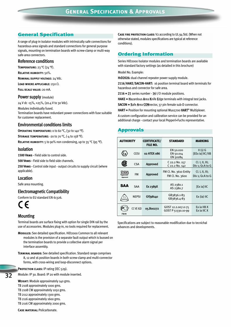
32
General Specification & Approvals
General SpecificationA range of plug-in isolator modules with intrinsically safe connections for
hazardous-area signals and standard connections for general purpose
signals, mounting on termination boards with screw-clamp or multi-way
safe-area connectors.
RReeffeerreennccee ccoonnddiittiioonnss
Temperature: 23 °C (74 °F).
Relative humidity: 50%.
Nominal supply voltage: 24 Vdc.
Load where applicable: 250 Ω.
Full scale value: 20 mA.
PPoowweerr ssuuppppllyy (module)
24 V dc -15%, +25%, (20.4 V to 30 Vdc).
Modules individually fused.
Termination boards have redundant power connections with fuse suitable
for customer replacement.
EEnnvviirroonnmmeennttaall ccoonnddiittiioonnss lliimmiittss
Operating temperature: 0 to 60 °C, (32 to 140 °F).
Storage temperature: -20 to 70 °C, (-4 to 158 °F).
Relative humidity: 5 to 90% non condensing, up to 35 °C (95 °F).
IIssoollaattiioonn
1500 Vrms - Field side to control side.
500 Vrms - Field side to field side channels.
250 Vrms - Control side input - output circuits to supply circuit (where
applicable).
LLooccaattiioonn
Safe area mounting.
EElleeccttrroommaaggnneettiicc CCoommppaattiibbiilliittyy
Conform to EU standard EN 61326.
MMoouunnttiinngg
Terminal boards are surface fixing with option for single DIN rail by the
use of accessories. Modules plug-in, no tools required for replacement.
Modules: See detailed specification. HiD2000 Common to all relevant
modules is the provision of a separate fault output which is bussed on
the termination boards to provide a collective alarm signal per
interface assembly.
Terminal boards: See detailed specification. Standard range comprises
8, 12 and 16 position boards in both screw-clamp and multi-connector
forms, with cross-wiring and loop-disconnect options.
Protection class: IP rating (IEC 529).
Module: IP 30. Board: IP 20 with module inserted.
Weight: Module approximately 140 gms.
TB 2108 approximately 1000 gms.
TB 2108 CW approximately 1050 gms.
TB 2112 approximately 1300 gms.
TB 2116 approximately 1600 gms.
TB 2116 CW approximately 2000 gms.
Case material: Policarbonate.
Case fire protection class: V2 according to UL 94 Std. (When not
otherwise stated, modules specifications are typical at reference
conditions).
Ordering InformationSeries HiD2000 Isolator modules and termination boards are available
with standard factory settings (as detailed in this brochure)
Model No. Example:
HiD2026: dual channel repeater power supply module.
2116/HAKE/SACON-HART: 16 position terminal board with terminals for
hazardous and connector for safe area.
2116 = 21 series number - 16 I/O module positions.
HAKE = Hazardous Area Knife Edge terminals with integral test jacks.
SACON = Safe Area CONnector, 37 pin female sub-D connector.
HART = Position for mounting optional Mux2700 HART® Multiplexer.
A custom configuration and calibration service can be provided for an
additional charge - contact your local Pepperl+Fuchs representative.
Approvals
AAUUTTHHOORRIITTYY CCEERRTTIIFFIICCAATTEE// SSTTAANNDDAARRDD MMAARRKKIINNGG FFIILLEE NNOO..
EN 50.020 II (1) GCESI 0022 AATTEEXX 008866 EN 50.014 [EEx ia] IIC/IIB
EN 50284
C 22.2 No. 157 CI. I, II, III; CSA AApppprroovveedd
C 22.2 No. 142 Div 1; Gr.A to G
FM CI. No. 3610 Entity CI. I, II, III; FM AApppprroovveedd
FM Cl. No. 3600 Div 1; Gr.A to G
AS 2380.1SAA EExx 22338899XX
AS 2380.7[Ex ia] IIC
NEPSI GGYYJJ9988114400GB3836.1-83
Ex (ia) IICGB3836.4-83
CC VE IGD 0055..BB0000227722GOST 12.2.007.0-75 Ex ia IIB XGOST P 51330.10-99 Ex ia IIC X
Ex
Specifications are subject to reasonable modification due to tecnichal
advances and developments.
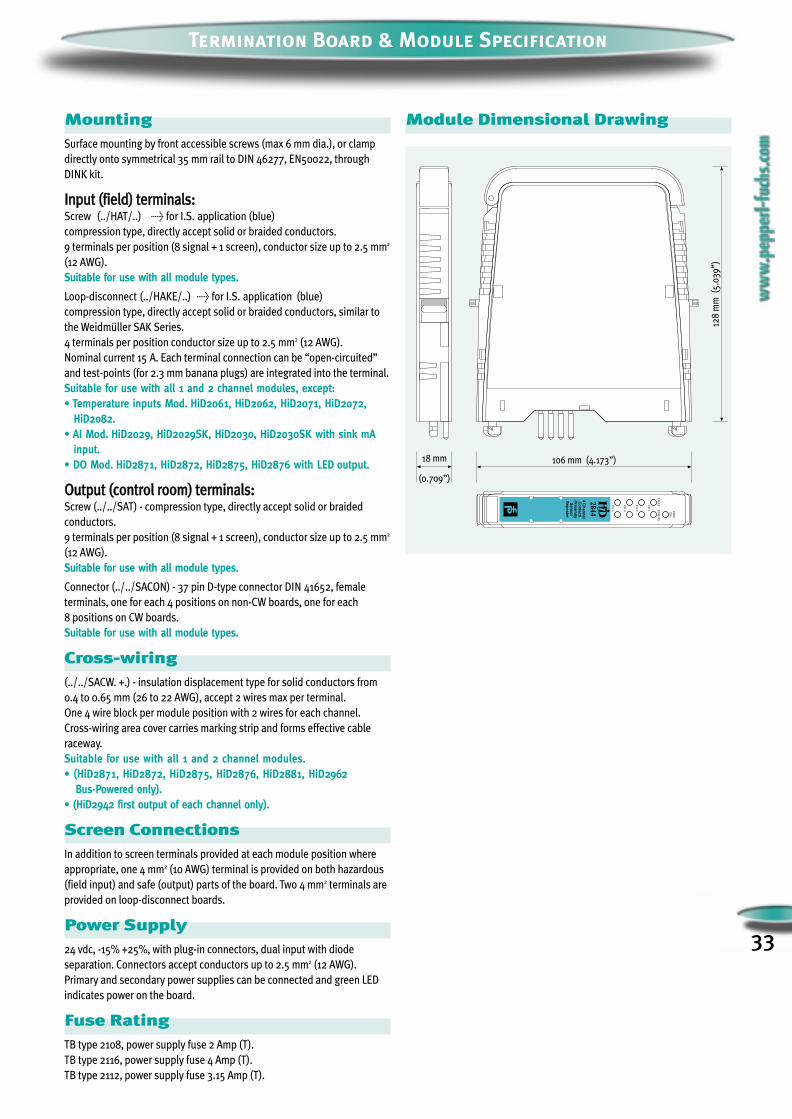
33
Termination Board & Module Specification
MountingSurface mounting by front accessible screws (max 6 mm dia.), or clamp
directly onto symmetrical 35 mm rail to DIN 46277, EN50022, through
DINK kit.
IInnppuutt ((ffiieelldd)) tteerrmmiinnaallss::Screw (../HAT/..) > for I.S. application (blue)
compression type, directly accept solid or braided conductors.
9 terminals per position (8 signal + 1 screen), conductor size up to 2.5 mm2
(12 AWG).
Suitable for use with all module types.
Loop-disconnect (../HAKE/..) > for I.S. application (blue)
compression type, directly accept solid or braided conductors, similar to
the Weidmüller SAK Series.
4 terminals per position conductor size up to 2.5 mm2 (12 AWG).
Nominal current 15 A. Each terminal connection can be “open-circuited”
and test-points (for 2.3 mm banana plugs) are integrated into the terminal.
Suitable for use with all 1 and 2 channel modules, except:• Temperature inputs Mod. HiD2061, HiD2062, HiD2071, HiD2072,
HiD2082.• AI Mod. HiD2029, HiD2029SK, HiD2030, HiD2030SK with sink mA
input.• DO Mod. HiD2871, HiD2872, HiD2875, HiD2876 with LED output.
OOuuttppuutt ((ccoonnttrrooll rroooomm)) tteerrmmiinnaallss::Screw (../../SAT) - compression type, directly accept solid or braided
conductors.
9 terminals per position (8 signal + 1 screen), conductor size up to 2.5 mm2
(12 AWG).
Suitable for use with all module types.
Connector (../../SACON) - 37 pin D-type connector DIN 41652, female
terminals, one for each 4 positions on non-CW boards, one for each
8 positions on CW boards.
Suitable for use with all module types.
Cross-wiring(../../SACW. +.) - insulation displacement type for solid conductors from
0.4 to 0.65 mm (26 to 22 AWG), accept 2 wires max per terminal.
One 4 wire block per module position with 2 wires for each channel.
Cross-wiring area cover carries marking strip and forms effective cable
raceway.
Suitable for use with all 1 and 2 channel modules.• (HiD2871, HiD2872, HiD2875, HiD2876, HiD2881, HiD2962
Bus-Powered only).• (HiD2942 first output of each channel only).
Screen ConnectionsIn addition to screen terminals provided at each module position where
appropriate, one 4 mm2 (10 AWG) terminal is provided on both hazardous
(field input) and safe (output) parts of the board. Two 4 mm2 terminals are
provided on loop-disconnect boards.
Power Supply24 vdc, -15% +25%, with plug-in connectors, dual input with diode
separation. Connectors accept conductors up to 2.5 mm2 (12 AWG).
Primary and secondary power supplies can be connected and green LED
indicates power on the board.
Fuse RatingTB type 2108, power supply fuse 2 Amp (T).
TB type 2116, power supply fuse 4 Amp (T).
TB type 2112, power supply fuse 3.15 Amp (T).
Module Dimensional Drawing
128
mm
(5
.03
9”)
18 mm
(0.709”)
106 mm (4.173”)
PW
RO
N
CH
1
CH
2
CH
4
CH
3
4 Channel
Contact/
Proxim
ityS
ensorR
epeater
2844
FAU
LTS
TAT
US
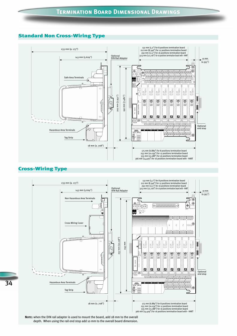
Safe Area Terminals
132 mm (5.2”) for 8 positions termination board212 mm (8.346”) for 12 positions termination board292 mm (11.5”) for 16 positions termination board
323 mm (12.716”) for 16 positions termination board with - HART143 mm (5.629")
20
2 m
m (
7.9
52
")
190
mm
(7
.48
0"
)
MO
DE
L 2
108
/HA
T/
SA
T
233 mm (9. 173”)
OptionalDIN Rail Adapter 10 mm
(0.393")
Optionalend stop
Hazardous Area Terminals
175 mm (6.889”) for 8 positions termination board255 mm (10.039”) for 12 positions termination board335 mm (13.188”) for 16 positions termination board
366 mm (14.409”) for 16 positions termination board with - HART
18 mm (0. 708”)
Tag Strip
PWRON
CH 1
CH 2
2 ChannelContact
Repeater
2842
FAULT STATUS
PWRON
CH 1
CH 2
2 ChannelContact
Repeater
2842
FAULT STATUS
PWRON
CH 1
CH 2
2 ChannelContact
Repeater
284
FAULT STATUS
PWRON
CH 1
CH 2
2 ChannelContact
Repeater
2842
FAULT STATUS
PWRON
CH 1
CH 2
2 ChannelContact
Repeater
2842
FAULT STATUS
PWRON
CH 1
CH 2
2 ChannelContact
Repeater
2842
FAULT STATUS
PWRON
CH 1
CH 2
2 ChannelContact
Repeater
2842
FAULT STATUS
PWRON
CH 1
CH 2
2 ChannelContact
Repeater
2842
FAULT STATUS
3 2 1
9 8 7
6 5 4
5 2 4 1
TERMINALCONNECTIONS
HAT Type HAKE Type
Termination Board Dimensional Drawings
34
Standard Non Cross-Wiring Type
Note: when the DIN rail adapter is used to mount the board, add 18 mm to the overall
depth. When using the rail end stop add 10 mm to the overall board dimension.
233 mm (9. 173”)
25
7 m
m (
10.1
18"
)
24
5 m
m
PWRON
CH 1
CH 2
2 ChannelContact
Repeater
2842
FAULT STATUS
PWRON
CH 1
CH 2
2 ChannelContact
Repeater
2842
FAULT STATUS
PWRON
CH 1
CH 2
2 ChannelContact
Repeater
2842
FAULT STATUS
PWRON
CH 1
CH 2
2 ChannelContact
Repeater
2842
FAULT STATUS
PWRON
CH 1
CH 2
2 ChannelContact
Repeater
2842
FAULT STATUS
PWRON
CH 1
CH 2
2 ChannelContact
Repeater
2842
FAULT STATUS
PWRON
CH 1
CH 2
2 ChannelContact
Repeater
2842
FAULT STATUS
PWRON
CH 1
CH 2
2 ChannelContact
Repeater
2842
FAULT STATUS
MODEL 2108/HAT/
Non Hazardous Area Terminals
10 mm
(0.393")
Cross Wiring Cover
143 mm (5.629")
132 mm (5.2”) for 8 positions termination board212 mm (8.346”) for 12 positions termination board292 mm (11.5”) for 16 positions termination board
323 mm (12.716”) for 16 positions termination board with - HART
Hazardous Area Terminals
Tag Strip
OptionalDIN Rail Adapter
18 mm (0. 708”) 175 mm (6.889”) for 8 positions termination board255 mm (10.039”) for 12 positions termination board335 mm (13.188”) for 16 positions termination board
366 mm (14.409”) for 16 positions termination board with - HART
Optionalend stop
Cross-Wiring Type
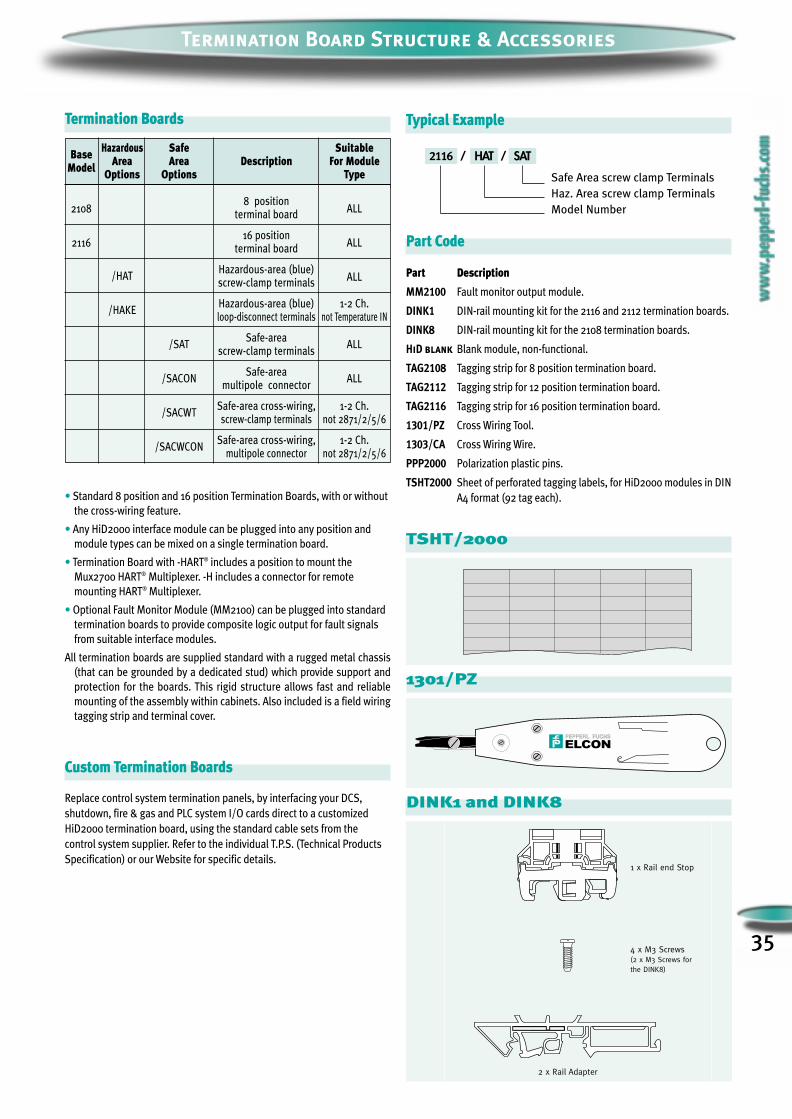
35
TSHT/2000
Termination Board Structure & Accessories
Base Hazardous Safe Suitable
Model Area Area Description For ModuleOptions Options Type
21088 position
ALLterminal board
211616 position
ALLterminal board
/HATHazardous-area (blue)
ALLscrew-clamp terminals
/HAKEHazardous-area (blue) 1-2 Ch.loop-disconnect terminals not Temperature IN
/SATSafe-area
ALLscrew-clamp terminals
/SACONSafe-area
ALLmultipole connector
/SACWTSafe-area cross-wiring, 1-2 Ch.screw-clamp terminals not 2871/2/5/6
/SACWCONSafe-area cross-wiring, 1-2 Ch.
multipole connector not 2871/2/5/6
Termination Boards
Safe Area screw clamp Terminals
Haz. Area screw clamp Terminals
Model Number
• Standard 8 position and 16 position Termination Boards, with or without
the cross-wiring feature.
• Any HiD2000 interface module can be plugged into any position and
module types can be mixed on a single termination board.
• Termination Board with -HART® includes a position to mount the
Mux2700 HART® Multiplexer. -H includes a connector for remote
mounting HART® Multiplexer.
• Optional Fault Monitor Module (MM2100) can be plugged into standard
termination boards to provide composite logic output for fault signals
from suitable interface modules.
All termination boards are supplied standard with a rugged metal chassis
(that can be grounded by a dedicated stud) which provide support and
protection for the boards. This rigid structure allows fast and reliable
mounting of the assembly within cabinets. Also included is a field wiring
tagging strip and terminal cover.
Part Code
Part Description
MM2100 Fault monitor output module.
DINK1 DIN-rail mounting kit for the 2116 and 2112 termination boards.
DINK8 DIN-rail mounting kit for the 2108 termination boards.
HiD blank Blank module, non-functional.
TAG2108 Tagging strip for 8 position termination board.
TAG2112 Tagging strip for 12 position termination board.
TAG2116 Tagging strip for 16 position termination board.
1301/PZ Cross Wiring Tool.
1303/CA Cross Wiring Wire.
PPP2000 Polarization plastic pins.
TSHT2000 Sheet of perforated tagging labels, for HiD2000 modules in DIN
A4 format (92 tag each).
Custom Termination Boards
Replace control system termination panels, by interfacing your DCS,
shutdown, fire & gas and PLC system I/O cards direct to a customized
HiD2000 termination board, using the standard cable sets from the
control system supplier. Refer to the individual T.P.S. (Technical Products
Specification) or our Website for specific details.
Typical Example
2116 SAT// HAT
1301/PZ
4 x M3 Screws(2 x M3 Screws forthe DINK8)
2 x Rail Adapter
1 x Rail end Stop
DINK1 and DINK8
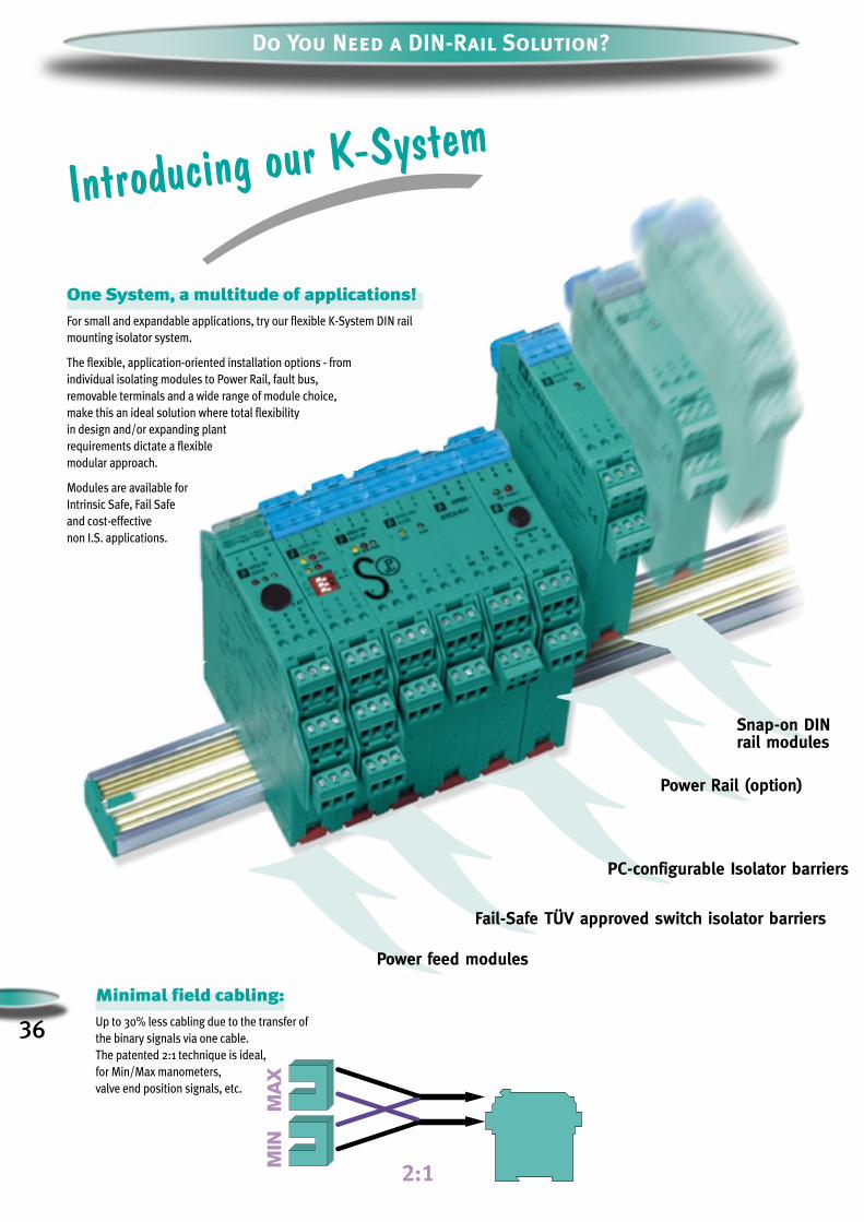
36
Do You Need a DIN-Rail Solution?
Minimal field cabling: Up to 30% less cabling due to the transfer of
the binary signals via one cable.
The patented 2:1 technique is ideal,
for Min/Max manometers,
valve end position signals, etc.
Snap-on DINrail modules
Power Rail (option)
PC-configurable Isolator barriers
Fail-Safe TÜV approved switch isolator barriers
Power feed modules
One System, a multitude of applications!For small and expandable applications, try our flexible K-System DIN rail
mounting isolator system.
The flexible, application-oriented installation options - from
individual isolating modules to Power Rail, fault bus,
removable terminals and a wide range of module choice,
make this an ideal solution where total flexibility
in design and/or expanding plant
requirements dictate a flexible
modular approach.
Modules are available for
Intrinsic Safe, Fail Safe
and cost-effective
non I.S. applications.
Introducing our K-System

37
Power Rail
The Power Rail is simply inserted in the standard DIN EN 50022 rail.
The rail then distributes power and fault signals to all modules which
snap onto the rail.
K-System Features
Need More Information?
Visit us at www.pepperl-fuchs.com or ask for acomplete Interface DIN-Rail Housing Catalog.
Power Distribution
Use one or two (redundancy) Power Module feeds to distribute power to
all modules and output the fault bus signal when sent by modules
plugged onto the Power Rail. The Power Feed Modules feature a 4 Amp
fuse and an internal alarm is signalled to indicate a defective fuses or
power fault.
Removable Terminals
The removable terminals permit rapid connection or replacement of
modules, as all wiring remains connected to the terminals.
All connectors are coded to avoid incorrect connections.
KF Profile
Use the special custom Aluminum KF Profile to maximise your cabinet
space and guarantee cable segregation.
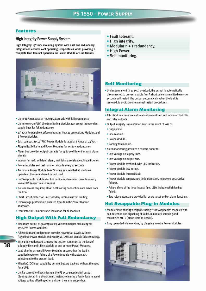
38
PS 1550 - Power Supply
Features
HHiigghh IInntteeggrriittyy PPoowweerr SSuuppppllyy SSyysstteemm..
High Integrity 19” rack mounting system with dual line redundancy.Integral fans ensures cool operating temperatures while providing acomplete fault tolerant operation for Power Module or Line failures.
• Up to 36 Amps total or 30 Amps at 24 Vdc with full redundancy.
• Up to two (1550/LM) Line Monitoring Modules can accept independentsupply lines for full redundancy.
• 19” rack for panel or surface mounting houses up to 2 Line Modules and6 Power Modules.
• Each compact (1550/PM) Power Module is rated at 6 Amps at 24 Vdc.
• Plug-in flexibility to add Power Modules for n+1 to 5 redundancy.
• Alarm bus provides output contacts for up to 10 different integral alarmsignals.
• Integral fan rack, with fault alarm, maintains a constant cooling efficiency.
• Power Modules self test for short circuits every 10 seconds.
• Automatic Power Module Load Sharing ensures that all modulesoperate at the same shared output load.
• Hot Swappable modules for live on-line replacement, provides a verylow MTTR (Mean Time To Repair).
• No rear access required, all AC & DC wiring connections are made fromthe front.
• Short Circuit protection is ensured by internal current limiting.
• Overvoltage protection is ensured by automatic Power Module shutdown.
• Front Panel LED alarm status indication for all modules
High Output With Full Redundancy • Maximum output of 36 Amps at 24 Vdc nominal per rack using six
1550/PM Power Modules.
• Fully redundant configuration provides 30 Amps at 24Vdc, with n+1(1550/PM) Power Module and two (1550/LM) Line Module failure strategy.
• With a fully redundant strategy the system is tolerant to the loss of1 Supply Line and 1 Line Module or one or more Power Modules.
• Load sharing across all Power Modules ensures that the load is supplied evenly on failure of a Power Module with automatic adjustment to the present load.
• Mixed AC/DC input capability permits battery back-up without the needfor a UPS.
• Unlike current fold back designs the PS 1550 supplies full output(60 Amps total) in a short circuit, instantly clearing a faulty fuse to avoidvoltage spikes affecting other units on the same supply bus.
Self Monitoring
• Under permanent ( > 10 sec.) overload, the output is automaticallydisconnected to prevent a cable fire. A short pulse transmitted every 10seconds will restart the output automatically when the fault isremoved, to avoid on-site manual restart procedures.
Integral Alarm Monitoring • All critical functions are automatically monitored and indicated by LED’s
and relay outputs.
• Output integrity is maintained even in the event of loss of:
• Supply line.
• Line Module.
• Power Module.
• Cooling fan module.
• Alarm monitoring provides a contact ouput for:
• Low voltage on supply lines.
• Low voltage on output bus.
• Power Module overload, with LED indication.
• Power Module low output.
• Power Module internal fault.
• Power Module temperature limit protection, to prevent destructivefailures.
• Failure of one of the three integral fans, LED’s indicate which fan hasfailed.
• Two relay outputs are provided for users to set and/or alarm functions.
Hot Swappable Plug-in Modules• Modular load sharing design including “Hot Swappable” modules with
self detection and signalling of faults, minimizes servicing andmaximises MTTR (Mean Time To Repair).
• Easy upgraded while on-line, by plugging in extra Power Modules.
• Fault tolerant.• High integrity. • Modular n + 1 redundancy.• High Power.• Self monitoring.
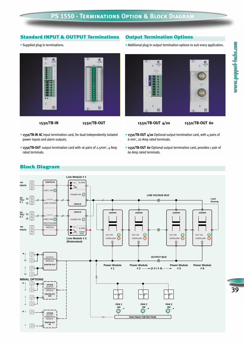
39
PS 1550 - Terminations Option & Block Diagram
Standard INPUT & OUTPUT Terminations
• Supplied plug-in terminations.
• 1550/TB-IN AC input termination card, for dual independently isolated
power inputs and alarm outputs.
• 1550/TB-OUT output termination card with 16 pairs of 2.5mm2, 4 Amp
rated terminals.
Output Termination Options
• Additional plug-in output termination options to suit every application.
• 1550/TB-OUT 4/20 Optional output termination card, with 4 pairs of
6 mm2, 20 Amp rated terminals.
• 1550/TB-OUT 60 Optional output termination card, provides 1 pair of
60 Amp rated terminals.
Power Module# 5
FAN 1OK
LINE 1 ON
/DCPPLYE 2
rmntacts
LINE FILTERS
INPUT/ALARMTERMINATION
MODULE
ALARM
ALARM
OUT ON
OVERLOAD
OUT ON
OVERLOAD
OUT ON
OVERLOAD
OUT ON
OVERLOAD
FaultOutput
LINE VOLTAGE BUS
OUTPUT BUS
Power Module# 1
Power Module# 2
Power Module# 6
Line Module # 1
Line Module # 2(Redundant)
rmntacts
/DCPPLYE 1
+OUTPUT
TERMINATIONMODULE
1550/TB-OUT
1
16
1
16
(# 3 / # 4)
FAN FAULT DETECTION
FAN 2OK
FAN 3OK
1550/LM
1550/LM
1550/TB-IN
1550/PM 1550/PM 1550/PM 1550/PM
LINE 2 ON
+OPTIONOUTPUT
TERMINATIONMODULE
1550/TB-OUT4/20
1
4
1
4
+OPTIONOUTPUT
TERMINATIONMODULE
1550/TB-OUT60
1
1
RMINAL OPTIONS
~~
~~ LoadSharing
POWER ON
POWER ON
Block Diagram
1550/TB-IN 1550/TB-OUT 1550/TB-OUT 4/20 1550/TB-OUT 60
PS 1550 TECHNICAL SPECIFICATIONS
40
InputInput line voltage (LINE 1 and/or LINE 2):
AC : 115 Vrms nominal ± 15% - (97.5 to 132 V) at 44 to 66 Hz
: 230 Vrms nominal ± 15% - (195 to 264 V) at 44 or 66 Hz
DC : 130 V nominal (110 to 180 V).
Line 1 to Line 2 switching (with two Line Modules):
Automatic, instantaneous in case of power down (semiconductor operated).
Important:
When using the PS-1550 with two independent supply lines they must be
isolated from each other, (i.e. using a 1:1 isolating transformer) to prevent
an interconnection of the lines outside the power supply, through the
common connected neutral.
Inrush current limiting:
Peak inrush current limited at 150% of full load peak current for each Line
Module (300% with two Line Modules).
Turn-on time: 250 ms nominal.
Steady state input current at full load (42 Amps out):
AC : 115 Vrms - 12 Amps average (36 Amps peak).
AC : 230 Vrms - 6 Amps average (18 Amps peak).
DC : 115 V - 11 Amps.
Line voltage bus under-voltage detection:
SPDT relay actuated below 70% of nominal input voltage.
Power module input under voltage lockout:
at 65% of nominal input voltage.
Internal fuses:
Fast acting 6.3 x 32 mm (1/4” x 1”1/4) 500 V/1500 Amps breaking capacity.
Ratings
Line Module (1550/LM)
AC : 115 V nominal 20 Amps (F1, F2) nominal 16 Amps (F3)
AC : 230 V nominal 10 Amps (F1, F2) nominal 8 Amps (F3)
Power Module (1550/PM)
AC : 115 V nominal 3.2 Amps
AC : 230 V nominal 1.6 Amps
Fans supply fuses: 500 mA (5x20 glass).
Input Terminals:
3 mains terminals per line 10 mm2.
OutputOUTPUT VOLTAGE:
24 Vdc ±1% - Adjustable from 22.5 to 28 V on Power Module.
Ripple:
30 mVrms, 100 mV pk to pk.
Temperature Coefficient of output voltage:
± 0.02% per °C max.
Line regulation:
< 200 mV output change for a Vmin to Vmax line change.
Load regulation:
less than 500 mV output change for a Zero to max output load.
Turn-on/Turn-off transient:
Voltage ramps to final value in 250 ms max (No over/ undershoot).
Under voltage alarm:
at 22 V ± 0.5 Volts.
Minimum hold-up time:
70 ms at nominal input voltage and load current.
OUTPUT CURRENT:
6 Amps nominal per Power Module (36 Amps total).
Overload alarm:
8 Amps nominal per Power Module (48 Amps total).
Short circuit limit:
10 Amps nominal per Power Module (60 Amps max). Timed for 10 sec
continual short before shutdown.
Short reset/retry cycle:
Cyclically the circuit provides short pulses at 10 Amps per module for
supply auto reset. At first short removal (V out ≥ 22 V), the system
automatically resets at the next retry cycle.
Output terminals:
• 1550/TB-OUT 32 output terminals with 16 pairs, 2.5 mm2 (12 AWG) 4 Amps
each.
Option:
• 1550/TB-OUT 4/20 four pairs of screw terminals 6 mm2 (10 AWG) 20 Amps
each.
• 1550 /TB-OUT 60 one pair output studs 60 Amps each.
General Isolation:
Output Versus Ground: 500 Vdc.
Line Versus Ground: (Y capacitors removed) 2500 Vrms.
Line Versus Output: (Y capacitors removed) 2500 Vrms.
Storage temperature:
-20 °C to +60 °C.
Operating temperature:
0 to +50 °C.
Conform to EU standard EN 61326.
Carries CE mark.

PS 1550 - Dimensions & Mounting: mm (inches)
41
16
101112
131415
16
101112
131415
123456789
~~
~~
OVERLOAD OVERLOAD OVERLOAD OVERLOAD OVERLOAD OVERLOAD
OUT ON OUT ON OUT ON OUT ON OUT ON OUT ONPOWER ONPOWER ON
LM1 LM2 PM1 PM2 PM3 PM4 PM5 PM6
RET. +OUT 24V
1 2ON
123456789
483 (19")
465 (18.3")
101
(3.
9")
176.
6 (
6.9"
)
F A N S1 2 3
Fan DetectionA
A
Front View
285
(11
.22"
)
+
+
+
Fans and Fault detection circuit are mounted under the support panel.
DetectionCircuitSupplyConnector
Fan FaultDetectionCircuit
Fuse 3
Fuse 2
Fuse 1
Fan 3
Fan 2
Fan 1
LD1 LD3LD2
Detection circuit Supply wire
(5 x 20glass500 mA)
supplyterminals
Optional rear panel mounting brackets
Fan Top View sect. A-A
101
(3.9
")
465 (18.3")
178
(7"
)
450 (17.7") ==
ø8 (0.31")
==
Cut Out (for front panel mounting)
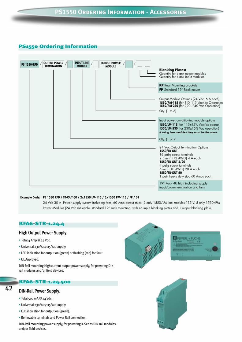
42
PS1550 Ordering Information - Accessories
PS 1550/RFD OUTPUT POWERTERMINATION
INPUT LINEMODULE
OUTPUT POWERMODULE
PS 1550 RFD / TB-OUT 60 / 2x1550 LM-115 / 5x1550 PM-115 / FP / 01
24 Vdc 30 A Power supply system including fans, 60 Amp output studs, 2 only 1550/LM line modules 115 V, 5 only 1550/PM
Power Modules (24 Vdc 6A each), standard 19” rack mounting, with no input blanking plates and 1 output blanking plate.
Example Code:
/ / / / /
24 Vdc Output Termination Options:1550/TB-OUT16 pairs screw terminals2.5 mm2 (12 AWG) 4 A each1550/TB-OUT 4/204 pairs screw terminals6 mm2 (10 AWG) 20 A each1550/TB-OUT 601 pair heavy duty stud 60 Amps each
Input power conditioning module options1550/LM-115 (for 115±15% Vac/dc operat.)1550/LM-230 (for 230±15% Vac operation)If using two modules they must be the same.
Qty. (1 or 2)
19” Rack 4U high including supplyinput/alarm termination and fans
Blanking Plates:Quantity for blank output modulesQuantity for blank input modules
RP Rear Mounting bracketsFP Standard 19” Rack mount
Output Module Options (24 Vdc, 6 A each)1550/PM-115 (for 110 -115 Vac/dc Operation1550/PM-230 (for 220 - 240 Vac Operation)
Qty. (1 to 6)
PS1550 Ordering Information
KFA6-STR-1.24.4
HHiigghh OOuuttppuutt PPoowweerr SSuuppppllyy..
• Total 4 Amp @ 24 Vdc.
• Universal 230 Vac/115 Vac supply.
• LED indication for output on (green) or flashing (red) for fault
• UL Approved.
DIN-Rail mounting High current output power supply, for powering DINrail modules and/or field devices.
KFA6-STR-1.24.500
DDIINN--RRaaiill PPoowweerr SSuuppppllyy..
• Total 500 mA @ 24 Vdc.
• Universal 230 Vac/115 Vac supply.
• LED indication for output on (green).
• Removable terminals and Power Rail connection.
DIN-Rail mounting power supply, for powering K-Series DIN rail modulesand/or field devices.

www.pepperl-fuchs.comWorldwide HeadquartersPepperl+Fuchs GmbH • Königsberger Allee 8768307 Mannheim - GermanyTel. +49 621 776-0 • Fax +49 621 776-10 00e-mail: [email protected]
USA HeadquartersPepperl+Fuchs Inc. • 1600 Enterprise ParkwayTwinsburg, Ohio 44087 • Cleveland - USATel. +330 425 35 55 • Fax +330 425 46 07e-mail: [email protected]
Asia Pacific HeadquartersPepperl+Fuchs Pte Ltd • P+F Building18 Ayer Rajah Crescent • Singapore 139942Tel. +65 779 90 91 • Fax +65 873 16 37e-mail: [email protected]
Italy HeadquartersPepperl+Fuchs Elcon Via delle Industrie, 4 • 20050 Mezzago (MI) - ItalyTel. +39 039 6292 1 • Fax +39 039 6292 390e-mail: [email protected]
Subject to reasonable modifications due to technical advances • Copyright PEPPERL+FUCHS ELCON • Printed in Italy • Part. No. 475191 11/2003 06
One Company, Two Divisions.Factory AutomationDivision
Product Range
Binary and analog sensorsin different technologies
Inductive and capacitive sensors Magnetic sensor Ultrasonic sensors Photoelectric sensors
Incremental and absolute rotary encoder Counters and control equipment Identification Systems AS-Interface
Areas of Application
Machine engineering Conveyor or transport Packaging and bottling Automobile industry
Service Area
Worldwide sales, customer service and consultation via competent and reliable Pepperl+Fuchsassociates ensure that you can contact us wherever or whenever you need us. We have subsidiariesworldwide for your convenience.
Product Range
Signal conditioners Intrinsically safe interface modules Remote process interface (RPI) Intrinsically safe field bus solutions Level control sensor HART® Multiplexer Process measuring and control systems
engineering at the interface level Intrinsic safety training
Areas of Application
Chemical industry Industrial and community sewage Oil, gas and petrochemical industry PLC and process control systems Engineering companies for process systems
Process AutomationDivision