Embed Size (px)
Citation preview

HC(S)08/RS08 and S12(X) Build Tools
Utilities Manual
Revised: 12 August 2010

Freescale, the Freescale logo, CodeWarrior and ColdFire are trademarks of Freescale Semiconductor, Inc., Reg. U.S.Pat. & Tm. Off. Flexis and Processor Expert are trademarks of Freescale Semiconductor, Inc. All other product or ser-vice names are the property of their respective owners.
© 2006-2010 Freescale Semiconductor, Inc. All rights reserved.
Information in this document is provided solely to enable system and software implementers to use Freescale Semicon-ductor products. There are no express or implied copyright licenses granted hereunder to design or fabricate any inte-grated circuits or integrated circuits based on the information in this document.
Freescale Semiconductor reserves the right to make changes without further notice to any products herein. FreescaleSemiconductor makes no warranty, representation or guarantee regarding the suitability of its products for any partic-ular purpose, nor does Freescale Semiconductor assume any liability arising out of the application or use of any productor circuit, and specifically disclaims any and all liability, including without limitation consequential or incidental dam-ages. “Typical” parameters that may be provided in Freescale Semiconductor data sheets and/or specifications can anddo vary in different applications and actual performance may vary over time. All operating parameters, including “Typ-icals”, must be validated for each customer application by customer's technical experts. Freescale Semiconductor doesnot convey any license under its patent rights nor the rights of others. Freescale Semiconductor products are not de-signed, intended, or authorized for use as components in systems intended for surgical implant into the body, or otherapplications intended to support or sustain life, or for any other application in which the failure of the Freescale Semi-conductor product could create a situation where personal injury or death may occur. Should Buyer purchase or useFreescale Semiconductor products for any such unintended or unauthorized application, Buyer shall indemnify and holdFreescale Semiconductor and its officers, employees, subsidiaries, affiliates, and distributors harmless against allclaims, costs, damages, and expenses, and reasonable attorney fees arising out of, directly or indirectly, any claim ofpersonal injury or death associated with such unintended or unauthorized use, even if such claim alleges that FreescaleSemiconductor was negligent regarding the design or manufacture of the part.
How to Contact Us
Corporate Headquarters Freescale Semiconductor, Inc.
6501 William Cannon Drive West
Austin, TX 78735
U.S.A.
World Wide Web http://www.freescale.com/codewarrior
Technical Support http://www.freescale.com/support

Table of Contents
IntroductionCodeWarrior IDE Utilities . . . . . . . . . . . . . . . . . . . . . . . . . . . . . . . . . . . . . . . . . 23
SmartLinker. . . . . . . . . . . . . . . . . . . . . . . . . . . . . . . . . . . . . . . . . . . . . . . . . . 23
Burner Utility . . . . . . . . . . . . . . . . . . . . . . . . . . . . . . . . . . . . . . . . . . . . . . . . 23
Libmaker . . . . . . . . . . . . . . . . . . . . . . . . . . . . . . . . . . . . . . . . . . . . . . . . . . . . 23
Decoder . . . . . . . . . . . . . . . . . . . . . . . . . . . . . . . . . . . . . . . . . . . . . . . . . . . . . 23
Maker: The Make Tool . . . . . . . . . . . . . . . . . . . . . . . . . . . . . . . . . . . . . . . . . 24
Starting a CodeWarrior Utility . . . . . . . . . . . . . . . . . . . . . . . . . . . . . . . . . . . . . . 24
I SmartLinkerPurpose of a Linker . . . . . . . . . . . . . . . . . . . . . . . . . . . . . . . . . . . . . . . . . . . . . . . 25
Product Features . . . . . . . . . . . . . . . . . . . . . . . . . . . . . . . . . . . . . . . . . . . . . . 25
Section Contents . . . . . . . . . . . . . . . . . . . . . . . . . . . . . . . . . . . . . . . . . . . . . . 26
Starting the SmartLinker Utility . . . . . . . . . . . . . . . . . . . . . . . . . . . . . . . . . . . . . 26
1 SmartLinker User Interface 29SmartLinker Main Window . . . . . . . . . . . . . . . . . . . . . . . . . . . . . . . . . . . . . . . . 29
Window Title . . . . . . . . . . . . . . . . . . . . . . . . . . . . . . . . . . . . . . . . . . . . . . . . . 30
Content Area . . . . . . . . . . . . . . . . . . . . . . . . . . . . . . . . . . . . . . . . . . . . . . . . . 30
Main Window Toolbar. . . . . . . . . . . . . . . . . . . . . . . . . . . . . . . . . . . . . . . . . . 31
Main Window Status Bar . . . . . . . . . . . . . . . . . . . . . . . . . . . . . . . . . . . . . . . 32
Main Window Menu Bar. . . . . . . . . . . . . . . . . . . . . . . . . . . . . . . . . . . . . . . . 32
SmartLinker Configuration Window. . . . . . . . . . . . . . . . . . . . . . . . . . . . . . . 34
Option Settings Window . . . . . . . . . . . . . . . . . . . . . . . . . . . . . . . . . . . . . . . . 41
Message Settings Window . . . . . . . . . . . . . . . . . . . . . . . . . . . . . . . . . . . . . . 43
About Dialog Box . . . . . . . . . . . . . . . . . . . . . . . . . . . . . . . . . . . . . . . . . . . . . 45
Retrieving Information about an Error Message. . . . . . . . . . . . . . . . . . . . . . 45
3HC(S)08/RS08 and S12(X) Build Tools Utilities Manual

Table of Contents
Specifying the Input File . . . . . . . . . . . . . . . . . . . . . . . . . . . . . . . . . . . . . . . .45
Using the Command Line in the Toolbar to Link . . . . . . . . . . . . . . . . . . . . .45
Message/Error Feedback . . . . . . . . . . . . . . . . . . . . . . . . . . . . . . . . . . . . . . . .46
2 SmartLinker Files 49Input Files . . . . . . . . . . . . . . . . . . . . . . . . . . . . . . . . . . . . . . . . . . . . . . . . . . . . . .49
Parameter File . . . . . . . . . . . . . . . . . . . . . . . . . . . . . . . . . . . . . . . . . . . . . . . .49
Object File . . . . . . . . . . . . . . . . . . . . . . . . . . . . . . . . . . . . . . . . . . . . . . . . . . .49
Output Files . . . . . . . . . . . . . . . . . . . . . . . . . . . . . . . . . . . . . . . . . . . . . . . . . . . . .50
Absolute Files . . . . . . . . . . . . . . . . . . . . . . . . . . . . . . . . . . . . . . . . . . . . . . . .50
S-Record Files . . . . . . . . . . . . . . . . . . . . . . . . . . . . . . . . . . . . . . . . . . . . . . . .50
Map Files . . . . . . . . . . . . . . . . . . . . . . . . . . . . . . . . . . . . . . . . . . . . . . . . . . . .50
Error Listing File . . . . . . . . . . . . . . . . . . . . . . . . . . . . . . . . . . . . . . . . . . . . . .52
3 Linking Issues 55Object Allocation . . . . . . . . . . . . . . . . . . . . . . . . . . . . . . . . . . . . . . . . . . . . . . . .55
The SEGMENTS Block (ELF) . . . . . . . . . . . . . . . . . . . . . . . . . . . . . . . . . . .55
The SECTIONS Block (Freescale + ELF) . . . . . . . . . . . . . . . . . . . . . . . . . .61
PLACEMENT Block. . . . . . . . . . . . . . . . . . . . . . . . . . . . . . . . . . . . . . . . . . .64
Initializing Vector Table . . . . . . . . . . . . . . . . . . . . . . . . . . . . . . . . . . . . . . . . . . .68
VECTOR Command . . . . . . . . . . . . . . . . . . . . . . . . . . . . . . . . . . . . . . . . . . .68
Smart Linking (ELF). . . . . . . . . . . . . . . . . . . . . . . . . . . . . . . . . . . . . . . . . . . . . .69
Mandatory Linking of an Object . . . . . . . . . . . . . . . . . . . . . . . . . . . . . . . . . .69
Mandatory Linking of all Objects Defined in Object File. . . . . . . . . . . . . . .70
Switching OFF Smart Linking for the Application . . . . . . . . . . . . . . . . . . . .70
Smart Linking (Freescale + ELF) . . . . . . . . . . . . . . . . . . . . . . . . . . . . . . . . . . . .71
Mandatory Linking from an Object. . . . . . . . . . . . . . . . . . . . . . . . . . . . . . . .71
Mandatory Linking from all Objects Defined in a File . . . . . . . . . . . . . . . .71
Binary Files Building an Application (ELF). . . . . . . . . . . . . . . . . . . . . . . . . . . .72
NAMES Block. . . . . . . . . . . . . . . . . . . . . . . . . . . . . . . . . . . . . . . . . . . . . . . .72
ENTRIES Block . . . . . . . . . . . . . . . . . . . . . . . . . . . . . . . . . . . . . . . . . . . . . .72
Binary Files Building an Application (Freescale). . . . . . . . . . . . . . . . . . . . . . . .73
NAMES Block. . . . . . . . . . . . . . . . . . . . . . . . . . . . . . . . . . . . . . . . . . . . . . . .73
Allocating Variables in OVERLAYS . . . . . . . . . . . . . . . . . . . . . . . . . . . . . . . . .74
Overlapping Locals . . . . . . . . . . . . . . . . . . . . . . . . . . . . . . . . . . . . . . . . . . . . . . .75
4 HC(S)08/RS08 and S12(X) Build Tools Utilities Manual

Table of Contents
Algorithm . . . . . . . . . . . . . . . . . . . . . . . . . . . . . . . . . . . . . . . . . . . . . . . . . . . 75
Name Mangling for Overlapping Locals . . . . . . . . . . . . . . . . . . . . . . . . . . . 77
Name Mangling in ELF Object File Format . . . . . . . . . . . . . . . . . . . . . . . . . 78
Defining a Function with Overlapping Parameters in Assembler. . . . . . . . . 79
DEPENDENCY TREE Section in Map File. . . . . . . . . . . . . . . . . . . . . . . . . 84
Optimizing the Overlap Size . . . . . . . . . . . . . . . . . . . . . . . . . . . . . . . . . . . . . 84
Recursion Checks . . . . . . . . . . . . . . . . . . . . . . . . . . . . . . . . . . . . . . . . . . . . . 85
Linker-Defined Objects. . . . . . . . . . . . . . . . . . . . . . . . . . . . . . . . . . . . . . . . . . . . 86
Stack Consumption Computation . . . . . . . . . . . . . . . . . . . . . . . . . . . . . . . . . . . . 89
STACK_CONSUMPTION Block. . . . . . . . . . . . . . . . . . . . . . . . . . . . . . . . . 89
Checksum Computation . . . . . . . . . . . . . . . . . . . . . . . . . . . . . . . . . . . . . . . . . . . 96
prm File-Controlled Checksum Computation . . . . . . . . . . . . . . . . . . . . . . . . 97
Automatic Linker-Controlled Checksum Computation . . . . . . . . . . . . . . . . 97
Partial Fields . . . . . . . . . . . . . . . . . . . . . . . . . . . . . . . . . . . . . . . . . . . . . . . . . 99
Runtime Support . . . . . . . . . . . . . . . . . . . . . . . . . . . . . . . . . . . . . . . . . . . . . . 99
Linking an Assembly Application . . . . . . . . . . . . . . . . . . . . . . . . . . . . . . . . . . 100
prm File . . . . . . . . . . . . . . . . . . . . . . . . . . . . . . . . . . . . . . . . . . . . . . . . . . . . 101
Warning Messages. . . . . . . . . . . . . . . . . . . . . . . . . . . . . . . . . . . . . . . . . . . . 101
Smart Linking . . . . . . . . . . . . . . . . . . . . . . . . . . . . . . . . . . . . . . . . . . . . . . . 102
LINK_INFO (ELF) . . . . . . . . . . . . . . . . . . . . . . . . . . . . . . . . . . . . . . . . . . . 104
4 SmartLinker Parameter File 105Parameter File Syntax . . . . . . . . . . . . . . . . . . . . . . . . . . . . . . . . . . . . . . . . . . . . 105
Mandatory SmartLinker Commands. . . . . . . . . . . . . . . . . . . . . . . . . . . . . . . . . 107
The INCLUDE Directive . . . . . . . . . . . . . . . . . . . . . . . . . . . . . . . . . . . . . . . . . 108
5 ELF Sections 109Segments and Sections . . . . . . . . . . . . . . . . . . . . . . . . . . . . . . . . . . . . . . . . . . . 109
Sections . . . . . . . . . . . . . . . . . . . . . . . . . . . . . . . . . . . . . . . . . . . . . . . . . . . . . . . 109
Predefined Sections . . . . . . . . . . . . . . . . . . . . . . . . . . . . . . . . . . . . . . . . . . . 110
Examples of Using Sections . . . . . . . . . . . . . . . . . . . . . . . . . . . . . . . . . . . . . . . 112
Example 1 . . . . . . . . . . . . . . . . . . . . . . . . . . . . . . . . . . . . . . . . . . . . . . . . . . 112
Example 2 . . . . . . . . . . . . . . . . . . . . . . . . . . . . . . . . . . . . . . . . . . . . . . . . . . 112
5HC(S)08/RS08 and S12(X) Build Tools Utilities Manual

Table of Contents
6 Segments 115Segments and Sections . . . . . . . . . . . . . . . . . . . . . . . . . . . . . . . . . . . . . . . . . . .115
Segment . . . . . . . . . . . . . . . . . . . . . . . . . . . . . . . . . . . . . . . . . . . . . . . . . . . . . . .115
Predefined Segments . . . . . . . . . . . . . . . . . . . . . . . . . . . . . . . . . . . . . . . . . .116
7 Program Startup 119Startup Descriptor (ELF). . . . . . . . . . . . . . . . . . . . . . . . . . . . . . . . . . . . . . . . . .119
User-Defined Startup Structure (ELF) . . . . . . . . . . . . . . . . . . . . . . . . . . . . . . .123
User-Defined Startup Routines (ELF). . . . . . . . . . . . . . . . . . . . . . . . . . . . . . . .124
Startup Descriptor (Freescale). . . . . . . . . . . . . . . . . . . . . . . . . . . . . . . . . . . . . .124
User-Defined Startup Routines (Freescale). . . . . . . . . . . . . . . . . . . . . . . . . . . .126
Example of Startup Code in ANSI-C . . . . . . . . . . . . . . . . . . . . . . . . . . . . .126
8 The Map File 133Map File Contents . . . . . . . . . . . . . . . . . . . . . . . . . . . . . . . . . . . . . . . . . . . . . . .133
9 ROM Libraries 135Creating a ROM Library . . . . . . . . . . . . . . . . . . . . . . . . . . . . . . . . . . . . . . . . . .135
ROM Libraries and Overlapping Locals . . . . . . . . . . . . . . . . . . . . . . . . . . .136
Using ROM Libraries . . . . . . . . . . . . . . . . . . . . . . . . . . . . . . . . . . . . . . . . . . . .136
Suppressing Initialization . . . . . . . . . . . . . . . . . . . . . . . . . . . . . . . . . . . . . .136
10 Initializing the Vector Table 143Using the SmartLinker prm File . . . . . . . . . . . . . . . . . . . . . . . . . . . . . . . . . . . .143
Using a Relocatable Section in the Assembly Source File . . . . . . . . . . . . . . . .145
Using an Absolute Section in the Assembly Source File . . . . . . . . . . . . . . . . .147
II Burner Utility Introduction . . . . . . . . . . . . . . . . . . . . . . . . . . . . . . . . . . . . . . . . . . . . . . . . . . . .151
Product Highlights. . . . . . . . . . . . . . . . . . . . . . . . . . . . . . . . . . . . . . . . . . . . . . .151
Starting the Burner Utility. . . . . . . . . . . . . . . . . . . . . . . . . . . . . . . . . . . . . . . . .152
6 HC(S)08/RS08 and S12(X) Build Tools Utilities Manual

Table of Contents
11 Interactive Burner GUI 155Burner Default Configuration Window. . . . . . . . . . . . . . . . . . . . . . . . . . . . . . . 155
Burner Dialog Box . . . . . . . . . . . . . . . . . . . . . . . . . . . . . . . . . . . . . . . . . . . . . . 156
Input/Output Tab . . . . . . . . . . . . . . . . . . . . . . . . . . . . . . . . . . . . . . . . . . . . . 156
Content Tab . . . . . . . . . . . . . . . . . . . . . . . . . . . . . . . . . . . . . . . . . . . . . . . . . 159
Command File Tab . . . . . . . . . . . . . . . . . . . . . . . . . . . . . . . . . . . . . . . . . . . 161
12 Batch Burner Language 163Batch Burner User Interface . . . . . . . . . . . . . . . . . . . . . . . . . . . . . . . . . . . . . . . 163
Syntax of Burner Command Files . . . . . . . . . . . . . . . . . . . . . . . . . . . . . . . . . . 164
Command File Comments. . . . . . . . . . . . . . . . . . . . . . . . . . . . . . . . . . . . . . 165
Batch Burner with Makefile . . . . . . . . . . . . . . . . . . . . . . . . . . . . . . . . . . . . . . . 165
Command File Examples . . . . . . . . . . . . . . . . . . . . . . . . . . . . . . . . . . . . . . 167
III Libmaker UtilityIntroduction. . . . . . . . . . . . . . . . . . . . . . . . . . . . . . . . . . . . . . . . . . . . . . . . . . . . 169
User Interface . . . . . . . . . . . . . . . . . . . . . . . . . . . . . . . . . . . . . . . . . . . . . . . . . . 169
Starting the Libmaker Utility . . . . . . . . . . . . . . . . . . . . . . . . . . . . . . . . . . . . . . 170
13 Libmaker Interface 171Startup Command Line Options . . . . . . . . . . . . . . . . . . . . . . . . . . . . . . . . . . . . 171
Command Line Interface . . . . . . . . . . . . . . . . . . . . . . . . . . . . . . . . . . . . . . . . . 171
Libmaker Commands . . . . . . . . . . . . . . . . . . . . . . . . . . . . . . . . . . . . . . . . . 172
Managing Libraries . . . . . . . . . . . . . . . . . . . . . . . . . . . . . . . . . . . . . . . . . . . 172
Libmaker Graphic User Interface . . . . . . . . . . . . . . . . . . . . . . . . . . . . . . . . . . . 175
Libmaker Default Configuration Window. . . . . . . . . . . . . . . . . . . . . . . . . . 175
Default Configuration Window Status Bar . . . . . . . . . . . . . . . . . . . . . . . . . 178
Configuration Window . . . . . . . . . . . . . . . . . . . . . . . . . . . . . . . . . . . . . . . . 182
Libmaker Option Settings Window. . . . . . . . . . . . . . . . . . . . . . . . . . . . . . . 190
Libmaker Message Settings Window . . . . . . . . . . . . . . . . . . . . . . . . . . . . . 191
About Libmaker Dialog Box. . . . . . . . . . . . . . . . . . . . . . . . . . . . . . . . . . . . 194
7HC(S)08/RS08 and S12(X) Build Tools Utilities Manual

Table of Contents
IV Decoder UtilityIntroduction . . . . . . . . . . . . . . . . . . . . . . . . . . . . . . . . . . . . . . . . . . . . . . . . . . . .195
Product Highlights. . . . . . . . . . . . . . . . . . . . . . . . . . . . . . . . . . . . . . . . . . . . . . .195
User Interface . . . . . . . . . . . . . . . . . . . . . . . . . . . . . . . . . . . . . . . . . . . . . . . . . .196
14 Input and Output Files 197Input Files . . . . . . . . . . . . . . . . . . . . . . . . . . . . . . . . . . . . . . . . . . . . . . . . . . . . .197
Absolute Files . . . . . . . . . . . . . . . . . . . . . . . . . . . . . . . . . . . . . . . . . . . . . . .197
Object File . . . . . . . . . . . . . . . . . . . . . . . . . . . . . . . . . . . . . . . . . . . . . . . . . .197
S-Record Files . . . . . . . . . . . . . . . . . . . . . . . . . . . . . . . . . . . . . . . . . . . . . . .198
Intel Hex Files . . . . . . . . . . . . . . . . . . . . . . . . . . . . . . . . . . . . . . . . . . . . . . .198
Output Files . . . . . . . . . . . . . . . . . . . . . . . . . . . . . . . . . . . . . . . . . . . . . . . . . . . .198
15 Decoder Controls 201List Menus. . . . . . . . . . . . . . . . . . . . . . . . . . . . . . . . . . . . . . . . . . . . . . . . . . . . .201
File Menu. . . . . . . . . . . . . . . . . . . . . . . . . . . . . . . . . . . . . . . . . . . . . . . . . . .202
Decoder Menu . . . . . . . . . . . . . . . . . . . . . . . . . . . . . . . . . . . . . . . . . . . . . . .203
View Menu. . . . . . . . . . . . . . . . . . . . . . . . . . . . . . . . . . . . . . . . . . . . . . . . . .203
Help Menu . . . . . . . . . . . . . . . . . . . . . . . . . . . . . . . . . . . . . . . . . . . . . . . . . .204
Graphical User Interface . . . . . . . . . . . . . . . . . . . . . . . . . . . . . . . . . . . . . . . . . .204
Decoder Main Window . . . . . . . . . . . . . . . . . . . . . . . . . . . . . . . . . . . . . . . .205
Decoder Configuration Window . . . . . . . . . . . . . . . . . . . . . . . . . . . . . . . . .207
Decoder Option Settings . . . . . . . . . . . . . . . . . . . . . . . . . . . . . . . . . . . . . . .212
About Decoder Dialog Box . . . . . . . . . . . . . . . . . . . . . . . . . . . . . . . . . . . . .216
Specifying the Input File . . . . . . . . . . . . . . . . . . . . . . . . . . . . . . . . . . . . . . . . . .216
Message and Error Feedback . . . . . . . . . . . . . . . . . . . . . . . . . . . . . . . . . . . . . .217
Using Information from the Main Window. . . . . . . . . . . . . . . . . . . . . . . . .217
Using a User-Defined Editor . . . . . . . . . . . . . . . . . . . . . . . . . . . . . . . . . . . .217
8 HC(S)08/RS08 and S12(X) Build Tools Utilities Manual

Table of Contents
V Maker Utility
16 Maker Controls 221Graphical User Interface . . . . . . . . . . . . . . . . . . . . . . . . . . . . . . . . . . . . . . . . . . 221
Maker Main Window. . . . . . . . . . . . . . . . . . . . . . . . . . . . . . . . . . . . . . . . . . 221
Main Window Components. . . . . . . . . . . . . . . . . . . . . . . . . . . . . . . . . . . . . 222
Maker Main Window Menu Bar . . . . . . . . . . . . . . . . . . . . . . . . . . . . . . . . . 222
Maker Main Window Toolbar . . . . . . . . . . . . . . . . . . . . . . . . . . . . . . . . . . . 226
Maker Configuration Window. . . . . . . . . . . . . . . . . . . . . . . . . . . . . . . . . . . 227
Maker Option Settings Window . . . . . . . . . . . . . . . . . . . . . . . . . . . . . . . . . 232
Maker Message Settings Window . . . . . . . . . . . . . . . . . . . . . . . . . . . . . . . . 233
About Dialog Box . . . . . . . . . . . . . . . . . . . . . . . . . . . . . . . . . . . . . . . . . . . . 235
Specifying the Input File. . . . . . . . . . . . . . . . . . . . . . . . . . . . . . . . . . . . . . . . . . 236
Message and Error Feedback . . . . . . . . . . . . . . . . . . . . . . . . . . . . . . . . . . . . . . 236
Using Information from the Main Window. . . . . . . . . . . . . . . . . . . . . . . . . 237
Using a User-Defined Editor . . . . . . . . . . . . . . . . . . . . . . . . . . . . . . . . . . . . 237
17 Using Maker 239Making Modula–2 Applications . . . . . . . . . . . . . . . . . . . . . . . . . . . . . . . . . . . . 239
Making C Applications . . . . . . . . . . . . . . . . . . . . . . . . . . . . . . . . . . . . . . . . . . . 239
Using Makefiles . . . . . . . . . . . . . . . . . . . . . . . . . . . . . . . . . . . . . . . . . . . . . 240
User-Defined Macros (Static Macros) . . . . . . . . . . . . . . . . . . . . . . . . . . . . . . . 242
Definition. . . . . . . . . . . . . . . . . . . . . . . . . . . . . . . . . . . . . . . . . . . . . . . . . . . 242
Reference. . . . . . . . . . . . . . . . . . . . . . . . . . . . . . . . . . . . . . . . . . . . . . . . . . . 242
Redefinition. . . . . . . . . . . . . . . . . . . . . . . . . . . . . . . . . . . . . . . . . . . . . . . . . 242
Macro Substitution . . . . . . . . . . . . . . . . . . . . . . . . . . . . . . . . . . . . . . . . . . . 242
Macros and Comments . . . . . . . . . . . . . . . . . . . . . . . . . . . . . . . . . . . . . . . . 243
Concatenation . . . . . . . . . . . . . . . . . . . . . . . . . . . . . . . . . . . . . . . . . . . . . . . 244
Command-Line Macros. . . . . . . . . . . . . . . . . . . . . . . . . . . . . . . . . . . . . . . . 244
Dynamic Macros. . . . . . . . . . . . . . . . . . . . . . . . . . . . . . . . . . . . . . . . . . . . . . . . 245
Inference Rules . . . . . . . . . . . . . . . . . . . . . . . . . . . . . . . . . . . . . . . . . . . . . . 246
Multiple Inference Rules. . . . . . . . . . . . . . . . . . . . . . . . . . . . . . . . . . . . . . . 248
Directives and Special Targets . . . . . . . . . . . . . . . . . . . . . . . . . . . . . . . . . . . . . 249
Built-In Commands . . . . . . . . . . . . . . . . . . . . . . . . . . . . . . . . . . . . . . . . . . . 250
9HC(S)08/RS08 and S12(X) Build Tools Utilities Manual

Table of Contents
Command Line . . . . . . . . . . . . . . . . . . . . . . . . . . . . . . . . . . . . . . . . . . . . . .252
Implementation Restrictions . . . . . . . . . . . . . . . . . . . . . . . . . . . . . . . . . . . .252
18 Building Libraries 253Maker Directory Structure . . . . . . . . . . . . . . . . . . . . . . . . . . . . . . . . . . . . . . . .253
Configuring WinEdit for the Maker . . . . . . . . . . . . . . . . . . . . . . . . . . . . . . . . .254
Configuring default.env for the Maker . . . . . . . . . . . . . . . . . . . . . . . . . . . . . . .255
Building Libraries with Defined Memory Model Options . . . . . . . . . . . . . . . .256
Building Libraries with Objects Added . . . . . . . . . . . . . . . . . . . . . . . . . . . . . .256
Structured Makefiles for Libraries . . . . . . . . . . . . . . . . . . . . . . . . . . . . . . . . . .258
VI Appendices
A Environment Variables 263Current Directory . . . . . . . . . . . . . . . . . . . . . . . . . . . . . . . . . . . . . . . . . . . . . . .264
Tool-Specific Search Information . . . . . . . . . . . . . . . . . . . . . . . . . . . . . . . . . . .265
Compiler . . . . . . . . . . . . . . . . . . . . . . . . . . . . . . . . . . . . . . . . . . . . . . . . . . .265
Debugger . . . . . . . . . . . . . . . . . . . . . . . . . . . . . . . . . . . . . . . . . . . . . . . . . . .265
Libmaker . . . . . . . . . . . . . . . . . . . . . . . . . . . . . . . . . . . . . . . . . . . . . . . . . . .265
Maker. . . . . . . . . . . . . . . . . . . . . . . . . . . . . . . . . . . . . . . . . . . . . . . . . . . . . .266
SmartLinker . . . . . . . . . . . . . . . . . . . . . . . . . . . . . . . . . . . . . . . . . . . . . . . . .266
Global Initialization File (MCUTOOLS.INI - PC Only) . . . . . . . . . . . . . . . . .267
[Installation] Section . . . . . . . . . . . . . . . . . . . . . . . . . . . . . . . . . . . . . . . . . .267
Path . . . . . . . . . . . . . . . . . . . . . . . . . . . . . . . . . . . . . . . . . . . . . . . . . . . . . . .267
Group . . . . . . . . . . . . . . . . . . . . . . . . . . . . . . . . . . . . . . . . . . . . . . . . . . . . . .268
[Options] Section. . . . . . . . . . . . . . . . . . . . . . . . . . . . . . . . . . . . . . . . . . . . .268
DefaultDir . . . . . . . . . . . . . . . . . . . . . . . . . . . . . . . . . . . . . . . . . . . . . . . . . .268
[Tool] Section . . . . . . . . . . . . . . . . . . . . . . . . . . . . . . . . . . . . . . . . . . . . . . .269
SaveOnExit . . . . . . . . . . . . . . . . . . . . . . . . . . . . . . . . . . . . . . . . . . . . . . . . .269
SaveAppearance. . . . . . . . . . . . . . . . . . . . . . . . . . . . . . . . . . . . . . . . . . . . . .269
SaveEditor . . . . . . . . . . . . . . . . . . . . . . . . . . . . . . . . . . . . . . . . . . . . . . . . . .270
SaveOptions . . . . . . . . . . . . . . . . . . . . . . . . . . . . . . . . . . . . . . . . . . . . . . . . .270
RecentProject0, RecentProject1, etc.. . . . . . . . . . . . . . . . . . . . . . . . . . . . . .270
10 HC(S)08/RS08 and S12(X) Build Tools Utilities Manual

Table of Contents
TipFilePos . . . . . . . . . . . . . . . . . . . . . . . . . . . . . . . . . . . . . . . . . . . . . . . . . . 271
ShowTipOfDay . . . . . . . . . . . . . . . . . . . . . . . . . . . . . . . . . . . . . . . . . . . . . . 271
TipTimeStamp. . . . . . . . . . . . . . . . . . . . . . . . . . . . . . . . . . . . . . . . . . . . . . . 271
[Editor] Section . . . . . . . . . . . . . . . . . . . . . . . . . . . . . . . . . . . . . . . . . . . . . . 272
Editor_Name . . . . . . . . . . . . . . . . . . . . . . . . . . . . . . . . . . . . . . . . . . . . . . . . 272
Editor_Exe. . . . . . . . . . . . . . . . . . . . . . . . . . . . . . . . . . . . . . . . . . . . . . . . . . 273
Editor_Opts . . . . . . . . . . . . . . . . . . . . . . . . . . . . . . . . . . . . . . . . . . . . . . . . . 273
Local Configuration File (usually project.ini) . . . . . . . . . . . . . . . . . . . . . . . . . 274
[Editor] Section . . . . . . . . . . . . . . . . . . . . . . . . . . . . . . . . . . . . . . . . . . . . . . 276
Editor_Name . . . . . . . . . . . . . . . . . . . . . . . . . . . . . . . . . . . . . . . . . . . . . . . . 276
Editor_Exe. . . . . . . . . . . . . . . . . . . . . . . . . . . . . . . . . . . . . . . . . . . . . . . . . . 276
Editor_Opts . . . . . . . . . . . . . . . . . . . . . . . . . . . . . . . . . . . . . . . . . . . . . . . . . 277
[Tool] Section . . . . . . . . . . . . . . . . . . . . . . . . . . . . . . . . . . . . . . . . . . . . . . . 277
RecentCommandLineX, X=Integer . . . . . . . . . . . . . . . . . . . . . . . . . . . . . . 277
CurrentCommandLine. . . . . . . . . . . . . . . . . . . . . . . . . . . . . . . . . . . . . . . . . 278
StatusbarEnabled. . . . . . . . . . . . . . . . . . . . . . . . . . . . . . . . . . . . . . . . . . . . . 278
ToolbarEnabled . . . . . . . . . . . . . . . . . . . . . . . . . . . . . . . . . . . . . . . . . . . . . . 279
WindowPos . . . . . . . . . . . . . . . . . . . . . . . . . . . . . . . . . . . . . . . . . . . . . . . . . 279
WindowFont . . . . . . . . . . . . . . . . . . . . . . . . . . . . . . . . . . . . . . . . . . . . . . . . 279
TipFilePos . . . . . . . . . . . . . . . . . . . . . . . . . . . . . . . . . . . . . . . . . . . . . . . . . . 280
ShowTipOfDay . . . . . . . . . . . . . . . . . . . . . . . . . . . . . . . . . . . . . . . . . . . . . . 280
Options . . . . . . . . . . . . . . . . . . . . . . . . . . . . . . . . . . . . . . . . . . . . . . . . . . . . 281
EditorType . . . . . . . . . . . . . . . . . . . . . . . . . . . . . . . . . . . . . . . . . . . . . . . . . . 281
EditorCommandLine. . . . . . . . . . . . . . . . . . . . . . . . . . . . . . . . . . . . . . . . . . 282
EditorDDEClientName . . . . . . . . . . . . . . . . . . . . . . . . . . . . . . . . . . . . . . . . 282
EditorDDETopicName . . . . . . . . . . . . . . . . . . . . . . . . . . . . . . . . . . . . . . . . 282
EditorDDEServiceName . . . . . . . . . . . . . . . . . . . . . . . . . . . . . . . . . . . . . . . 283
Burner Dialog Entries in [BURNER] . . . . . . . . . . . . . . . . . . . . . . . . . . . . . 283
BurnerUndefByte . . . . . . . . . . . . . . . . . . . . . . . . . . . . . . . . . . . . . . . . . . . . 283
BurnerSwapByte . . . . . . . . . . . . . . . . . . . . . . . . . . . . . . . . . . . . . . . . . . . . . 284
BurnerOrigin . . . . . . . . . . . . . . . . . . . . . . . . . . . . . . . . . . . . . . . . . . . . . . . . 284
BurnerDestination . . . . . . . . . . . . . . . . . . . . . . . . . . . . . . . . . . . . . . . . . . . . 284
BurnerLength . . . . . . . . . . . . . . . . . . . . . . . . . . . . . . . . . . . . . . . . . . . . . . . 285
BurnerFormat . . . . . . . . . . . . . . . . . . . . . . . . . . . . . . . . . . . . . . . . . . . . . . . 285
BurnerDataBus . . . . . . . . . . . . . . . . . . . . . . . . . . . . . . . . . . . . . . . . . . . . . . 286
11HC(S)08/RS08 and S12(X) Build Tools Utilities Manual

Table of Contents
BurnerOutputType . . . . . . . . . . . . . . . . . . . . . . . . . . . . . . . . . . . . . . . . . . . .286
BurnerDataBits . . . . . . . . . . . . . . . . . . . . . . . . . . . . . . . . . . . . . . . . . . . . . .287
BurnerParity. . . . . . . . . . . . . . . . . . . . . . . . . . . . . . . . . . . . . . . . . . . . . . . . .287
BurnerByteCommands . . . . . . . . . . . . . . . . . . . . . . . . . . . . . . . . . . . . . . . .287
BurnerBaudRate . . . . . . . . . . . . . . . . . . . . . . . . . . . . . . . . . . . . . . . . . . . . .288
BurnerOutputFile. . . . . . . . . . . . . . . . . . . . . . . . . . . . . . . . . . . . . . . . . . . . .288
BurnerHeaderFile . . . . . . . . . . . . . . . . . . . . . . . . . . . . . . . . . . . . . . . . . . . .289
BurnerInputFile . . . . . . . . . . . . . . . . . . . . . . . . . . . . . . . . . . . . . . . . . . . . . .289
Configuration File Example . . . . . . . . . . . . . . . . . . . . . . . . . . . . . . . . . . . .290
Paths . . . . . . . . . . . . . . . . . . . . . . . . . . . . . . . . . . . . . . . . . . . . . . . . . . . . . . . . .291
Line Continuation . . . . . . . . . . . . . . . . . . . . . . . . . . . . . . . . . . . . . . . . . . . . . . .292
Environment Variable Details . . . . . . . . . . . . . . . . . . . . . . . . . . . . . . . . . . . . . .293
ABSPATH: Absolute Path . . . . . . . . . . . . . . . . . . . . . . . . . . . . . . . . . . . . . .293
COMP: Modula-2 Compiler . . . . . . . . . . . . . . . . . . . . . . . . . . . . . . . . . . . .294
COPYRIGHT: Copyright Entry in Absolute File . . . . . . . . . . . . . . . . . . . .295
DEFAULTDIR: Default Current Directory . . . . . . . . . . . . . . . . . . . . . . . . .295
ENVIRONMENT: Environment File Specification . . . . . . . . . . . . . . . . . .296
ERRORFILE: Error File Name Specification . . . . . . . . . . . . . . . . . . . . . . .297
FLAGS: Options for Modula-2 Compiler . . . . . . . . . . . . . . . . . . . . . . . . . .300
GENPATH: Define Paths to Search for Input Files . . . . . . . . . . . . . . . . . . .300
INCLUDETIME: Creation Time in Object File . . . . . . . . . . . . . . . . . . . . .301
LINK: Linker for Modula-2. . . . . . . . . . . . . . . . . . . . . . . . . . . . . . . . . . . . .302
LINKOPTIONS: Default SmartLinker Options . . . . . . . . . . . . . . . . . . . . .302
OBJPATH: Object File Path . . . . . . . . . . . . . . . . . . . . . . . . . . . . . . . . . . . .303
RESETVECTOR: Reset Vector Location . . . . . . . . . . . . . . . . . . . . . . . . . .304
SRECORD: S Record File Format . . . . . . . . . . . . . . . . . . . . . . . . . . . . . . .304
TEXTFAMILY: Text Font Family . . . . . . . . . . . . . . . . . . . . . . . . . . . . . . . .305
TEXTKIND: Text Font Character Set . . . . . . . . . . . . . . . . . . . . . . . . . . . . .306
TEXTPATH: Text Path . . . . . . . . . . . . . . . . . . . . . . . . . . . . . . . . . . . . . . . .307
TEXTSIZE: Text Font Size . . . . . . . . . . . . . . . . . . . . . . . . . . . . . . . . . . . . .307
TEXTSTYLE: Text Font Style . . . . . . . . . . . . . . . . . . . . . . . . . . . . . . . . . .308
TMP: Temporary Directory . . . . . . . . . . . . . . . . . . . . . . . . . . . . . . . . . . . . .309
USERNAME: User Name in Object File . . . . . . . . . . . . . . . . . . . . . . . . . .310
12 HC(S)08/RS08 and S12(X) Build Tools Utilities Manual

Table of Contents
B Tool Options 311Option Details . . . . . . . . . . . . . . . . . . . . . . . . . . . . . . . . . . . . . . . . . . . . . . . . . . 312
Special Modifiers . . . . . . . . . . . . . . . . . . . . . . . . . . . . . . . . . . . . . . . . . . . . 313
-A: Print Full Listing (Decoder) . . . . . . . . . . . . . . . . . . . . . . . . . . . . . . . . . 314
-A: Warning for Missing .DEF File (Maker) . . . . . . . . . . . . . . . . . . . . . . . 316
-Add: Additional Object/Library File . . . . . . . . . . . . . . . . . . . . . . . . . . . . . 316
-Alloc: Allocation Over Segment Boundaries (ELF) . . . . . . . . . . . . . . . . . 317
-AsROMLib: Link as ROM Library . . . . . . . . . . . . . . . . . . . . . . . . . . . . . . 319
-B: Generate S-Record file (SmartLinker) . . . . . . . . . . . . . . . . . . . . . . . . . 319
-C: Write Disassembly Listing with Source Code (Decoder) . . . . . . . . . . . 320
-C: Ignore Case (Maker) . . . . . . . . . . . . . . . . . . . . . . . . . . . . . . . . . . . . . . . 321
-CAllocUnusedOverlap: Allocate Unreferenced Overlap Variables (Freescale) . . . . . . . . . . . . . . . . . . . . . . . . . . . . . . . . . . . . . . . . . . . . . . . 322
-Ci: Link Case Insensitive . . . . . . . . . . . . . . . . . . . . . . . . . . . . . . . . . . . . . . 322
-Cmd: Libmaker Commands. . . . . . . . . . . . . . . . . . . . . . . . . . . . . . . . . . . . 323
-Cocc: Optimize Common Code (ELF) . . . . . . . . . . . . . . . . . . . . . . . . . . . 324
-CRam: Allocate Non-specified Constant Segments in RAM (ELF) . . . . . 325
-D: Display Dialog Box (Burner) . . . . . . . . . . . . . . . . . . . . . . . . . . . . . . . . 326
-D: Decode DWARF Sections (Decoder) . . . . . . . . . . . . . . . . . . . . . . . . . . 326
-D: Define a Macro (Maker) . . . . . . . . . . . . . . . . . . . . . . . . . . . . . . . . . . . . 328
-Disp: Display Mode (Maker) . . . . . . . . . . . . . . . . . . . . . . . . . . . . . . . . . . . 329
-Dist: Enable Distribution Optimization (ELF) (SmartLinker). . . . . . . . . . 329
-DistFile: Specify Distribution File Name (ELF) (SmartLinker) . . . . . . . . 330
-DistInfo: Generate Distribution Information File (ELF) (SmartLinker) . . 330
-DistOpti: Choose Optimizing Method (ELF) (SmartLinker) . . . . . . . . . . 331
-DistSeg: Specify Distribution Segment Name (ELF) (SmartLinker) . . . . 332
-E: Define Application Entry Point (ELF) (SmartLinker) . . . . . . . . . . . . . 332
-E: Decode ELF sections (Decoder) . . . . . . . . . . . . . . . . . . . . . . . . . . . . . . 333
-E: Unknown Macros as Empty Strings (Maker) . . . . . . . . . . . . . . . . . . . . 335
-Ed: Dump ELF Sections in LST File (Decoder) . . . . . . . . . . . . . . . . . . . . 336
-Env: Set Environment Variable . . . . . . . . . . . . . . . . . . . . . . . . . . . . . . . . . 336
-F: Execute Command File (Burner). . . . . . . . . . . . . . . . . . . . . . . . . . . . . . 337
-F: Object File Format (Decoder) . . . . . . . . . . . . . . . . . . . . . . . . . . . . . . . . 338
-FA, -FE, -FH -F6: Object File Format (SmartLinker) . . . . . . . . . . . . . . . . 339
13HC(S)08/RS08 and S12(X) Build Tools Utilities Manual

Table of Contents
-H: Prints the List of All Available Options (Short Help) . . . . . . . . . . . . . .339
-I: Ignore Exit Codes (Maker) . . . . . . . . . . . . . . . . . . . . . . . . . . . . . . . . . . .341
-L: Add a Path to Search Path (ELF) (SmartLinker) . . . . . . . . . . . . . . . . . .341
-L: Produce Inline Assembly File (Decoder). . . . . . . . . . . . . . . . . . . . . . . .342
-L: List Modules (Maker) . . . . . . . . . . . . . . . . . . . . . . . . . . . . . . . . . . . . . .343
-LibFile . . . . . . . . . . . . . . . . . . . . . . . . . . . . . . . . . . . . . . . . . . . . . . . . . . . .343
-LibOptions . . . . . . . . . . . . . . . . . . . . . . . . . . . . . . . . . . . . . . . . . . . . . . . . .344
-Lic: Print License Information . . . . . . . . . . . . . . . . . . . . . . . . . . . . . . . . . .344
-LicA: License Information About Every Feature in Directory . . . . . . . . .345
-LicBorrow: Borrow License Feature . . . . . . . . . . . . . . . . . . . . . . . . . . . . .345
-LicWait: Wait for Floating License from Floating License Server . . . . . .346
-M: Generate Map File (SmartLinker) . . . . . . . . . . . . . . . . . . . . . . . . . . . .347
-M: Produce Make File (Maker) . . . . . . . . . . . . . . . . . . . . . . . . . . . . . . . . .347
-Mar: Freescale Archive Commands (Libmaker) . . . . . . . . . . . . . . . . . . . .348
-MkAll: Make Always (Maker). . . . . . . . . . . . . . . . . . . . . . . . . . . . . . . . . .349
-N: Display Notify Box . . . . . . . . . . . . . . . . . . . . . . . . . . . . . . . . . . . . . . . .349
-NoBeep: No Beep in Case of an Error . . . . . . . . . . . . . . . . . . . . . . . . . . . .351
-NoCapture: Do Not Redirect stdout of Called Processes (Maker). . . . . . .351
-NoEnv: Do Not Use Environment . . . . . . . . . . . . . . . . . . . . . . . . . . . . . . .352
-NoPath: Strip Path Info (Libmaker) . . . . . . . . . . . . . . . . . . . . . . . . . . . . . .353
-NoSym: No Symbols in Disassembled Listing (Decoder). . . . . . . . . . . . .353
-Ns: Configure S-Records (Burner). . . . . . . . . . . . . . . . . . . . . . . . . . . . . . .354
-O: Define Absolute File Name (SmartLinker) . . . . . . . . . . . . . . . . . . . . . .355
-O: Defines Listing File Name (Decoder) . . . . . . . . . . . . . . . . . . . . . . . . . .356
-O: Compile Only (Maker) . . . . . . . . . . . . . . . . . . . . . . . . . . . . . . . . . . . . .357
-OCopy: Optimize Copy Down (ELF) (SmartLinker). . . . . . . . . . . . . . . . .357
-Options . . . . . . . . . . . . . . . . . . . . . . . . . . . . . . . . . . . . . . . . . . . . . . . . . . . .358
-OptionFile. . . . . . . . . . . . . . . . . . . . . . . . . . . . . . . . . . . . . . . . . . . . . . . . . .358
-P2LibFile . . . . . . . . . . . . . . . . . . . . . . . . . . . . . . . . . . . . . . . . . . . . . . . . . .359
-Proc: Set Processor (Decoder) . . . . . . . . . . . . . . . . . . . . . . . . . . . . . . . . . .359
-Prod: Specify Project File at Startup (PC) (No d, no m) . . . . . . . . . . . . . .360
-ReadLibFile . . . . . . . . . . . . . . . . . . . . . . . . . . . . . . . . . . . . . . . . . . . . . . . .361
-S: Do Not Generate DWARF Information (ELF) (SmartLinker). . . . . . . .361
-S: Silent Mode (Maker) . . . . . . . . . . . . . . . . . . . . . . . . . . . . . . . . . . . . . . .362
-SFixups: Creating Fixups (ELF) (SmartLinker) . . . . . . . . . . . . . . . . . . . .362
14 HC(S)08/RS08 and S12(X) Build Tools Utilities Manual

Table of Contents
-StartUpInfo . . . . . . . . . . . . . . . . . . . . . . . . . . . . . . . . . . . . . . . . . . . . . . . . 363
-StatF: Specify Name of Statistic File (SmartLinker) . . . . . . . . . . . . . . . . . 363
-T: Show Cycle Count for Each Instruction (Decoder). . . . . . . . . . . . . . . . 364
-V: Prints Tool Version . . . . . . . . . . . . . . . . . . . . . . . . . . . . . . . . . . . . . . . . 365
-View: Application Standard Occurrence (PC) . . . . . . . . . . . . . . . . . . . . . . 365
-W: Display Window (Burner) . . . . . . . . . . . . . . . . . . . . . . . . . . . . . . . . . . 366
-W1: No Information Messages . . . . . . . . . . . . . . . . . . . . . . . . . . . . . . . . . 367
-W2: No Information and Warning Messages. . . . . . . . . . . . . . . . . . . . . . . 367
-WErrFile: Create “err.log” Error File . . . . . . . . . . . . . . . . . . . . . . . . . . . . 368
-Wmsg8x3: Cut File Names in Microsoft Format to 8.3 (PC) . . . . . . . . . . 369
-WmsgCE: RGB Color for Error Messages . . . . . . . . . . . . . . . . . . . . . . . . 370
-WmsgCF: RGB Color for Fatal Messages. . . . . . . . . . . . . . . . . . . . . . . . . 370
-WmsgCI: RGB Color for Information Messages . . . . . . . . . . . . . . . . . . . 371
-WmsgCU: RGB Color for User Messages . . . . . . . . . . . . . . . . . . . . . . . . 372
-WmsgCW: RGB Color for Warning Messages . . . . . . . . . . . . . . . . . . . . . 372
-WmsgFb (-WmsgFbv, -WmsgFbm): Set Message File Format for Batch Mode . . . . . . . . . . . . . . . . . . . . . . . . . . . . . . . . . . . . . . . . . . . . . . . . . . . 373
-WmsgFi: Set Message File Format for Interactive Mode . . . . . . . . . . . . . 374
-WmsgFob: Message Format for Batch Mode . . . . . . . . . . . . . . . . . . . . . . 376
-WmsgFoi: Message Format for Interactive Mode . . . . . . . . . . . . . . . . . . . 378
-WmsgFonf: Message Format for no File Information . . . . . . . . . . . . . . . . 379
-WmsgFonp: Message Format for No Position Information. . . . . . . . . . . . 380
-WmsgNe: Number of Error Messages. . . . . . . . . . . . . . . . . . . . . . . . . . . . 382
-WmsgNi: Number of Information Messages. . . . . . . . . . . . . . . . . . . . . . . 383
-WmsgNu: Disable User Messages. . . . . . . . . . . . . . . . . . . . . . . . . . . . . . . 384
-WmsgNw: Number of Warning Messages. . . . . . . . . . . . . . . . . . . . . . . . . 384
-WmsgSd: Setting a Message to Disable . . . . . . . . . . . . . . . . . . . . . . . . . . 385
-WmsgSe: Setting a Message to Error . . . . . . . . . . . . . . . . . . . . . . . . . . . . 386
-WmsgSi: Setting a Message to Information . . . . . . . . . . . . . . . . . . . . . . . 387
-WmsgVrb: Verbose Mode (Maker) . . . . . . . . . . . . . . . . . . . . . . . . . . . . . . 387
-WmsgSw: Setting a Message to Warning . . . . . . . . . . . . . . . . . . . . . . . . . 388
-WOutFile: Create Error Listing File . . . . . . . . . . . . . . . . . . . . . . . . . . . . . 389
-WStdout: Write to Standard Output. . . . . . . . . . . . . . . . . . . . . . . . . . . . . . 390
-X: Write Disassembled Listing Only (Decoder) . . . . . . . . . . . . . . . . . . . . 390
-Y: Write Disassembled Listing with Source And All Comments (Decoder) .
15HC(S)08/RS08 and S12(X) Build Tools Utilities Manual

Table of Contents
392
C Messages 393Types of Generated Messages . . . . . . . . . . . . . . . . . . . . . . . . . . . . . . . . . . . . . .393
Message Details. . . . . . . . . . . . . . . . . . . . . . . . . . . . . . . . . . . . . . . . . . . . . . . . .393
Burner Message List . . . . . . . . . . . . . . . . . . . . . . . . . . . . . . . . . . . . . . . . . . . . .394
B1: Unknown Message Occurred . . . . . . . . . . . . . . . . . . . . . . . . . . . . . . . .394
B2: Message Overflow, Skipping <kind> Messages . . . . . . . . . . . . . . . . . .395
B50: Input file ‘<file>’ not found . . . . . . . . . . . . . . . . . . . . . . . . . . . . . . . .395
B51: Cannot Open Statistic Log File <file> . . . . . . . . . . . . . . . . . . . . . . . .395
B52: Error in Command Line '<cmd>. . . . . . . . . . . . . . . . . . . . . . . . . . . . .396
B64: Line Continuation Occurred in <FileName> . . . . . . . . . . . . . . . . . . .396
B65: Environment Macro Expansion Error '<description>' for <variablename> . . . . . . . . . . . . . . . . . . . . . . . . . . . . . . . . . . . . . . . . . . .397
B66: Search Path <Name> Does Not Exist . . . . . . . . . . . . . . . . . . . . . . . . .397
B1000: Could Not Open '<FileType>' '<File>. . . . . . . . . . . . . . . . . . . . . . .398
B1001: Error in Input File Format. . . . . . . . . . . . . . . . . . . . . . . . . . . . . . . .398
B1002: Selected Communication Port is Busy . . . . . . . . . . . . . . . . . . . . . .398
B1003: Timeout or Failure for the Selected Communication . . . . . . . . . . .399
B1004: Error in Macro ‘<macro>’ at Position <pos>: ‘<msg>’ . . . . . . . . .399
B1005: Error in Command Line at Position <pos>: ‘<msg>’. . . . . . . . . . .399
B1006: ‘<msg>’. . . . . . . . . . . . . . . . . . . . . . . . . . . . . . . . . . . . . . . . . . . . . .400
Libmaker Message List . . . . . . . . . . . . . . . . . . . . . . . . . . . . . . . . . . . . . . . . . . .400
LM1: Unknown Message Occurred. . . . . . . . . . . . . . . . . . . . . . . . . . . . . . .400
LM2: Message Overflow, Skipping <kind> Messages . . . . . . . . . . . . . . . .400
LM50: Input File ‘<file>’ Not Found . . . . . . . . . . . . . . . . . . . . . . . . . . . . .401
LM51: Cannot Open Statistic Log File <file>. . . . . . . . . . . . . . . . . . . . . . .401
LM52: Error in Command Line <cmd> . . . . . . . . . . . . . . . . . . . . . . . . . . .401
LM64: Line Continuation Occurred in <FileName>. . . . . . . . . . . . . . . . . .402
LM65: Environment Macro Expansion Message '<description>' for <variablename> . . . . . . . . . . . . . . . . . . . . . . . . . . . . . . . . . . . . . . . . . . .403
LM66: Search Path <Name> Does Not Exist . . . . . . . . . . . . . . . . . . . . . . .403
Decoder Message List . . . . . . . . . . . . . . . . . . . . . . . . . . . . . . . . . . . . . . . . . . . .404
D1: Unknown Message Occurred . . . . . . . . . . . . . . . . . . . . . . . . . . . . . . . .404
D2: Message Overflow, Skipping <kind> Messages. . . . . . . . . . . . . . . . . .404
16 HC(S)08/RS08 and S12(X) Build Tools Utilities Manual

Table of Contents
D50: Input File ‘<file>’ Not Found. . . . . . . . . . . . . . . . . . . . . . . . . . . . . . . 404
D51: Cannot Open Statistic Log File <file> . . . . . . . . . . . . . . . . . . . . . . . . 405
D52: Error in Command Line <cmd>. . . . . . . . . . . . . . . . . . . . . . . . . . . . . 405
D64: Line Continuation Occurred in <FileName> . . . . . . . . . . . . . . . . . . . 405
D65: Environment Macro Expansion Message '<description>' for <variablename> . . . . . . . . . . . . . . . . . . . . . . . . . . . . . . . . . . . . . . . . . . . 406
D66: Search Path <Name> Does Not Exist . . . . . . . . . . . . . . . . . . . . . . . . 407
D1000: Bad Hex Input File <Description>. . . . . . . . . . . . . . . . . . . . . . . . . 407
D1001: Because Current Processor is Unknown, No Disassembly is Generated. Use -proc. . . . . . . . . . . . . . . . . . . . . . . . . . . . . . . . . . . . . . . 407
Makefile Messages . . . . . . . . . . . . . . . . . . . . . . . . . . . . . . . . . . . . . . . . . . . . . . 408
M1: Unknown Message Occurred. . . . . . . . . . . . . . . . . . . . . . . . . . . . . . . . 408
M2: Message Overflow, Skipping <kind> Messages . . . . . . . . . . . . . . . . . 408
M50: Input File ‘<file>’ Not Found . . . . . . . . . . . . . . . . . . . . . . . . . . . . . . 409
M51: Cannot Open Statistic Log File <file>. . . . . . . . . . . . . . . . . . . . . . . . 409
M64: Line Continuation Occurred in <FileName>. . . . . . . . . . . . . . . . . . . 409
M65: Environment Macro Expansion Error '<description>' for <variablename> . . . . . . . . . . . . . . . . . . . . . . . . . . . . . . . . . . . . . . . . . . . 410
M66: Search Path <Name> Does Not Exist . . . . . . . . . . . . . . . . . . . . . . . . 411
M5000: User Requested Stop . . . . . . . . . . . . . . . . . . . . . . . . . . . . . . . . . . . 411
M5001: Error in Command Line. . . . . . . . . . . . . . . . . . . . . . . . . . . . . . . . . 412
M5002: Can't Return to <makefile> at End of Include File . . . . . . . . . . . . 412
M5003: Illegal Dependency . . . . . . . . . . . . . . . . . . . . . . . . . . . . . . . . . . . . 413
M5004: Illegal Macro Reference . . . . . . . . . . . . . . . . . . . . . . . . . . . . . . . . 413
M5005: Macro Substitution Too Complex . . . . . . . . . . . . . . . . . . . . . . . . . 414
M5006: Macro Reference Not Closed . . . . . . . . . . . . . . . . . . . . . . . . . . . . 414
M5007: Unknown Macro: <macroname>. . . . . . . . . . . . . . . . . . . . . . . . . . 414
M5008: Macro Definition or Command Line Too Long . . . . . . . . . . . . . . 415
M5009: Illegal Include Directive . . . . . . . . . . . . . . . . . . . . . . . . . . . . . . . . 415
M5010: Illegal Line. . . . . . . . . . . . . . . . . . . . . . . . . . . . . . . . . . . . . . . . . . . 415
M5011: Illegal Suffix for Inference Rule . . . . . . . . . . . . . . . . . . . . . . . . . . 416
M5012: Include File Not Found: <includefile> . . . . . . . . . . . . . . . . . . . . . 416
M5013: Include File Too Long: <includefile> . . . . . . . . . . . . . . . . . . . . . . 417
M5014: Circular Macro Substitution in <macroname> . . . . . . . . . . . . . . . 417
M5015: Colon (:) Expected . . . . . . . . . . . . . . . . . . . . . . . . . . . . . . . . . . . . 417
17HC(S)08/RS08 and S12(X) Build Tools Utilities Manual

Table of Contents
M5016: Filename After INCLUDE Expected. . . . . . . . . . . . . . . . . . . . . . .418
M5017: Circular Include, File <includefile>. . . . . . . . . . . . . . . . . . . . . . . .418
M5018: Entry Doesn't Start at Column 0 . . . . . . . . . . . . . . . . . . . . . . . . . .418
M5019: No Makefile Found . . . . . . . . . . . . . . . . . . . . . . . . . . . . . . . . . . . .419
M5020: Fatal Error During Initialization . . . . . . . . . . . . . . . . . . . . . . . . . .419
M5021: Nothing to Make: No Target Found . . . . . . . . . . . . . . . . . . . . . . . .419
M5022: Don't Know How to Make <target>. . . . . . . . . . . . . . . . . . . . . . . .420
M5023: Circular Dependencies Between <target1> and <target2> . . . . . .420
M5024: Illegal Option . . . . . . . . . . . . . . . . . . . . . . . . . . . . . . . . . . . . . . . . .421
M5027: Making Target <target> . . . . . . . . . . . . . . . . . . . . . . . . . . . . . . . . .421
M5028: Command Line Too Long: <commandline> . . . . . . . . . . . . . . . . .422
M5029: Illegal Target Name: <targetname> . . . . . . . . . . . . . . . . . . . . . . . .422
Exec Process Messages . . . . . . . . . . . . . . . . . . . . . . . . . . . . . . . . . . . . . . . . . . .422
M5100: Command Line Too Long for Exec . . . . . . . . . . . . . . . . . . . . . . . .422
M5101: Two File Names Expected . . . . . . . . . . . . . . . . . . . . . . . . . . . . . . .423
M5102: Input File Not Found . . . . . . . . . . . . . . . . . . . . . . . . . . . . . . . . . . .423
M5103: Output File Not Opened. . . . . . . . . . . . . . . . . . . . . . . . . . . . . . . . .423
M5104: Error While Copying . . . . . . . . . . . . . . . . . . . . . . . . . . . . . . . . . . .424
M5105: Renaming Failed . . . . . . . . . . . . . . . . . . . . . . . . . . . . . . . . . . . . . .424
M5106: File Name Expected . . . . . . . . . . . . . . . . . . . . . . . . . . . . . . . . . . . .425
M5107: File Does Not Exist . . . . . . . . . . . . . . . . . . . . . . . . . . . . . . . . . . . .425
M5108: Called Application Detected an Error . . . . . . . . . . . . . . . . . . . . . .425
M5109: Echo <commandline> . . . . . . . . . . . . . . . . . . . . . . . . . . . . . . . . . .426
M5110: Called Application Caused a System Error . . . . . . . . . . . . . . . . . .426
M5111: Change Directory (cd) Failed. . . . . . . . . . . . . . . . . . . . . . . . . . . . .426
M5112: Called Application: <error>. . . . . . . . . . . . . . . . . . . . . . . . . . . . . .427
M5113: Called Application: <warning> . . . . . . . . . . . . . . . . . . . . . . . . . . .427
M5114: Called Application: <information> . . . . . . . . . . . . . . . . . . . . . . . .428
M5115: Called Application: <fatal> . . . . . . . . . . . . . . . . . . . . . . . . . . . . . .428
M5116: Could Not Delete File . . . . . . . . . . . . . . . . . . . . . . . . . . . . . . . . . .429
M5117: Path Was Not Found. . . . . . . . . . . . . . . . . . . . . . . . . . . . . . . . . . . .429
M5118: Could Not Create Process: <diagnostic> . . . . . . . . . . . . . . . . . . . .430
M5119: Exec <commandline> . . . . . . . . . . . . . . . . . . . . . . . . . . . . . . . . . .430
M5120: Running Version with Limited Number of Execution Calls. Number of Allowed Execution Calls Exceeded. . . . . . . . . . . . . . . . . . . . . . . . . .430
18 HC(S)08/RS08 and S12(X) Build Tools Utilities Manual

Table of Contents
M5121: The Files <file1> and <file2> Are Not Identical. . . . . . . . . . . . . . 431
M5122: The Files <file1> and <file2> Are Identical . . . . . . . . . . . . . . . . . 431
M5153: Processing Make Files Under Win32s Is Not Supported by the Maker431
Modula-2 Maker Messages. . . . . . . . . . . . . . . . . . . . . . . . . . . . . . . . . . . . . . . . 432
M5700: Environment Variable COMP Not Set. . . . . . . . . . . . . . . . . . . . . . 432
M5701: Environment Variable LINK Not Set . . . . . . . . . . . . . . . . . . . . . . 432
M5702: Neither Source Nor Symbol File Found: <source file>. . . . . . . . . 432
M5703: Circular Imports in Definition Modules . . . . . . . . . . . . . . . . . . . . 433
M5704: Can't Recompile <source file> (No Source Found). . . . . . . . . . . . 433
M5705: No Make File Generated (Top Module Not Found) . . . . . . . . . . . 433
M5706: Couldn't Open the Listing File <list file> . . . . . . . . . . . . . . . . . . . 434
M5708: Couldn't Open the Makefile. . . . . . . . . . . . . . . . . . . . . . . . . . . . . . 434
M5761: Wrote Makefile <makefile> . . . . . . . . . . . . . . . . . . . . . . . . . . . . . 435
M5762: Wrote Listing File <listfile> . . . . . . . . . . . . . . . . . . . . . . . . . . . . . 435
M5763: Compilation Sequence. . . . . . . . . . . . . . . . . . . . . . . . . . . . . . . . . . 435
D Tool Commands 437SmartLinker Commands . . . . . . . . . . . . . . . . . . . . . . . . . . . . . . . . . . . . . . . . . . 437
AUTO_LOAD: Load Imported Modules (Freescale, M2) . . . . . . . . . . . . . 437
CHECKSUM: Checksum Computation (ELF) . . . . . . . . . . . . . . . . . . . . . . 438
CHECKKEYS: Check Module Keys (Freescale, M2) . . . . . . . . . . . . . . . . 441
DATA: Specify the RAM Start (Freescale) . . . . . . . . . . . . . . . . . . . . . . . . . 442
DEPENDENCY: Dependency Control . . . . . . . . . . . . . . . . . . . . . . . . . . . . 442
ENTRIES: List of Objects to Link with Application . . . . . . . . . . . . . . . . . 447
HAS_BANKED_DATA: Application Has Banked Data (Freescale) . . . . . 449
HEXFILE: Link Hex File with Application . . . . . . . . . . . . . . . . . . . . . . . . 449
INIT: Specify Application Init Point. . . . . . . . . . . . . . . . . . . . . . . . . . . . . . 450
LINK: Specify Name of Output File. . . . . . . . . . . . . . . . . . . . . . . . . . . . . . 451
MAIN: Name of Application Root Function . . . . . . . . . . . . . . . . . . . . . . . 452
MAPFILE: Configure Map File Content . . . . . . . . . . . . . . . . . . . . . . . . . . 453
NAMES: List Files Building the Application . . . . . . . . . . . . . . . . . . . . . . . 455
OVERLAP_GROUP: Application Uses Overlapping (ELF) . . . . . . . . . . . 456
PLACEMENT: Place Sections into Segments . . . . . . . . . . . . . . . . . . . . . . 458
PRESTART: Application Prestart Code (Freescale) . . . . . . . . . . . . . . . . . . 460
19HC(S)08/RS08 and S12(X) Build Tools Utilities Manual

Table of Contents
SECTIONS: Define Memory Map (Freescale) . . . . . . . . . . . . . . . . . . . . . .461
SEGMENTS: Define Memory Map (ELF) . . . . . . . . . . . . . . . . . . . . . . . . .463
STACKSIZE: Define Stack Size . . . . . . . . . . . . . . . . . . . . . . . . . . . . . . . . .471
STACKTOP: Define Stack Pointer Initial Value . . . . . . . . . . . . . . . . . . . . .473
START: Specify the ROM Start (Freescale) . . . . . . . . . . . . . . . . . . . . . . . .474
VECTOR: Initialize Vector Table . . . . . . . . . . . . . . . . . . . . . . . . . . . . . . . .474
Batch Burner Commands . . . . . . . . . . . . . . . . . . . . . . . . . . . . . . . . . . . . . . . . .476
baudRate: Baudrate for Serial Communication. . . . . . . . . . . . . . . . . . . . . .477
busWidth: Data Bus Width . . . . . . . . . . . . . . . . . . . . . . . . . . . . . . . . . . . . .478
CLOSE: Close Open File or Communication Port . . . . . . . . . . . . . . . . . . .478
dataBit: Number of Data Bits . . . . . . . . . . . . . . . . . . . . . . . . . . . . . . . . . . .479
destination: Destination Offset . . . . . . . . . . . . . . . . . . . . . . . . . . . . . . . . . .480
DO: For Loop Statement List . . . . . . . . . . . . . . . . . . . . . . . . . . . . . . . . . . .480
ECHO: Echo String onto Output Window. . . . . . . . . . . . . . . . . . . . . . . . . .481
ELSE: Else Part of If Condition . . . . . . . . . . . . . . . . . . . . . . . . . . . . . . . . .482
END: For Loop End or If End . . . . . . . . . . . . . . . . . . . . . . . . . . . . . . . . . . .483
FOR: For Loop . . . . . . . . . . . . . . . . . . . . . . . . . . . . . . . . . . . . . . . . . . . . . .484
format: Output Format. . . . . . . . . . . . . . . . . . . . . . . . . . . . . . . . . . . . . . . . .485
header: Header File for PROM Burner . . . . . . . . . . . . . . . . . . . . . . . . . . . .485
IF: If Condition . . . . . . . . . . . . . . . . . . . . . . . . . . . . . . . . . . . . . . . . . . . . . .486
len: Length to be Copied . . . . . . . . . . . . . . . . . . . . . . . . . . . . . . . . . . . . . . .487
OPENCOM: Open Output Communication Port . . . . . . . . . . . . . . . . . . . .488
OPENFILE: Open Output File . . . . . . . . . . . . . . . . . . . . . . . . . . . . . . . . . .488
origin: EEPROM Start Address. . . . . . . . . . . . . . . . . . . . . . . . . . . . . . . . . .489
parity: Set Communication Parity . . . . . . . . . . . . . . . . . . . . . . . . . . . . . . . .490
SENDBYTE: Transfer Bytes. . . . . . . . . . . . . . . . . . . . . . . . . . . . . . . . . . . .490
SENDWORD: Transfer Words . . . . . . . . . . . . . . . . . . . . . . . . . . . . . . . . . .491
SLINELEN: SRecord Line Length . . . . . . . . . . . . . . . . . . . . . . . . . . . . . . .493
SRECORD: S-Record Type. . . . . . . . . . . . . . . . . . . . . . . . . . . . . . . . . . . . .494
swapByte: Swap Bytes . . . . . . . . . . . . . . . . . . . . . . . . . . . . . . . . . . . . . . . .495
THEN: Statementlist for If Condition . . . . . . . . . . . . . . . . . . . . . . . . . . . . .495
TO: For Loop End Condition. . . . . . . . . . . . . . . . . . . . . . . . . . . . . . . . . . . .496
undefByte: Fill Byte for Binary Files . . . . . . . . . . . . . . . . . . . . . . . . . . . . .497
PAUSE: Wait until Key Pressed. . . . . . . . . . . . . . . . . . . . . . . . . . . . . . . . . .498
20 HC(S)08/RS08 and S12(X) Build Tools Utilities Manual

Table of Contents
E EBNF Notation 499Introduction to EBNF . . . . . . . . . . . . . . . . . . . . . . . . . . . . . . . . . . . . . . . . . . . . 499
EBNF Example . . . . . . . . . . . . . . . . . . . . . . . . . . . . . . . . . . . . . . . . . . . . . . 499
EBNF Syntax. . . . . . . . . . . . . . . . . . . . . . . . . . . . . . . . . . . . . . . . . . . . . . . . 500
Extensions . . . . . . . . . . . . . . . . . . . . . . . . . . . . . . . . . . . . . . . . . . . . . . . . . . 500
Index 503
21HC(S)08/RS08 and S12(X) Build Tools Utilities Manual

Table of Contents
22 HC(S)08/RS08 and S12(X) Build Tools Utilities Manual

Introduction
CodeWarrior IDE UtilitiesThe HC(S)08, RS08 and S12(X) Build Tools Utilities Manual describes the following five CodeWarrior IDE utilities:
• SmartLinker
• Burner Utility
• Libmaker
• Decoder
• Maker: The Make Tool
SmartLinkerThe CodeWarrior IDE SmartLinker utility merges the various object files of an application into one absolute file (or .ABS file) that can be converted to an S-Record or an Intel® Hex file, using the Burner program, or loaded into the target using the Downloader/Debugger.
This utility is a “smart linker”, linking only those objects that are actually used by your application. This linker is able to generate either Freescale or ELF absolute files.
Burner UtilityThe CodeWarrior IDE burner utility converts an .ABS file into a file that can be handled by an EPROM burner.
LibmakerThe CodeWarrior IDE Libmaker utility creates and maintains object file libraries.
DecoderThe CodeWarrior IDE ELF/Freescale Decoder utility disassembles object files, absolute files and libraries in the Freescale object file format or ELF/DWARF format, along with S-Record files.
23HC(S)08/RS08 and S12(X) Build Tools Utilities Manual

Starting a CodeWarrior Utility
Maker: The Make ToolThe CodeWarrior IDE Maker utility implements the UNIX make command with a Graphical User Interface (GUI). In addition, you can use Maker to build Modula-2 applications as well as maintain C/C++ projects.
Starting a CodeWarrior UtilityYou can start all of the utilities described in this book from executable files located in the prog folder of your CodeWarrior IDE installation. The executable files are:
• maker.exe Maker: The Make Tool
• burner.exe The Burner Utility
• decoder.exe The Decoder
• libmaker.exe Libmaker
• linker.exe SmartLinker
A standard full installation of the HC(S)08/RS08 CodeWarrior IDE places the executable files in this location:
C:\Program Files\Freescale\CodeWarrior for Microcontrollers V6.2\Prog
A standard full installation of the HC(S)12 CodeWarrior IDE places the executable files in this location:
C:\Program Files\Freescale\CodeWarrior for S12(X) V5.x\Prog
To start any CodeWarrior Utility, click on the appropriate executable file (*.exe).
24 HC(S)08/RS08 and S12(X) Build Tools Utilities Manual

I
SmartLinker
This chapter describes the SmartLinker utility. The linker merges the various object files of an application into one absolute file (or .ABS file). The file is called absolute file because it contains absolute, not relocatable cod. You can convert this .ABS file to an S-Record or an Intel Hex file using the Burner program or load the .ABS file into the target using the Downloader/Debugger.
The Linker is a smart linker. It links only those objects that are actually used by your application.
This linker is able to generate either Freescale or ELF absolute files. For compatibility purposes, the Freescale input syntax is also supported when ELF absolute files are generated.
Purpose of a LinkerLinking is the process of assigning memory to all global objects (functions, global data, strings, and initialization data) needed for a given application and combining these objects into a format suitable for downloading into a target system or an emulator.
The linker is a smart linker: it links only those objects that are actually used by the application. Unused functions and variables won’t occupy any memory in the target system. Other optimizations that reduce memory requirements include storing initialized parts of global variables in compact forms, and reserving memory only once for equal strings.
Product FeaturesThe most important features supported by the SmartLinker are:
• Complete control over the placement of objects in memory: it is possible to allocate different groups of functions or variables to different memory areas (Segmentation; see the Segments and Sections chapters).
• Linking to objects already allocated in a previous link session (ROM libraries).
25HC(S)08/RS08 and S12(X) Build Tools Utilities Manual

Starting the SmartLinker Utility
NOTE The code for application startup is a separate file written in inline assembly and can be easily adapted to your particular needs. In this manual, the startup file is called startup. However, this is a generic file name that has to be replaced by the real target startup file name. See the README.TXT file in the appropriate subdirectory of the installation LIB directory for more details about memory models and associated startup codes.
• Mixed-language linking: Modula-2, assembly, and C object files can be mixed, even in the same application.
• Vector initialization.
Section ContentsThis section consists of the following chapters:
• SmartLinker User Interface — Describes the features of the SmartLinker user interface
• SmartLinker Files — Describes the input and output files used by the SmartLinker
• Linking Issues — Discusses linking features and issues
• SmartLinker Parameter File — Describes the requirements of the SmartLinker parameter file
• ELF Sections — Describes the use of sections and segments for ELF and provides examples using sections to control allocation of variables and functions
• Segments — Describes the use of sections and segments for Freescale
• Program Startup — Provides advanced material on using startup routines
• The Map File — Describes the contents of the map file produced by the link process
• ROM Libraries —Describes creating and using ROM libraries
• Initializing the Vector Table — Describes initializing the vector table
Starting the SmartLinker UtilityAll utilities described in this book may be started from executable files located in the prog folder of your IDE installation. The executable files are:
• maker.exe Maker: The Make Tool
• burner.exe The Burner Utility
• decoder.exe The Decoder
• libmaker.exe Libmaker
26 HC(S)08/RS08 and S12(X) Build Tools Utilities Manual

Starting the SmartLinker Utility
• linker.exe SmartLinker
With a standard full installation of the HC(S)08/RS08 CodeWarrior IDE, the executable files are located at:
C:\Program Files\Freescale\CodeWarrior for Microcontrollers V6.2\Prog
With a standard full installation of the HC(S)12 CodeWarrior IDE, the executable files are located at:
C:\Program Files\Freescale\CodeWarrior for S12(X) V5.x\Prog
To start the SmartLinker Utility, click on linker.exe.
27HC(S)08/RS08 and S12(X) Build Tools Utilities Manual

Starting the SmartLinker Utility
28 HC(S)08/RS08 and S12(X) Build Tools Utilities Manual

1SmartLinker User Interface
The SmartLinker runs under Win32. Start the linker from the CodeWarrior installation prog folder.
SmartLinker Main WindowThe SmartLinker Main window provides a window title, a menu bar, a toolbar, a content area, and a status bar, as shown in Figure 1.1.
Figure 1.1 SmartLinker Main Window
29HC(S)08/RS08 and S12(X) Build Tools Utilities Manual

SmartLinker User InterfaceSmartLinker Main Window
Window TitleThe window title displays the project name. If currently no project is loaded, Default Configuration appears in the title. A “*” after the configuration name indicates that some values have changed. The “*” appears as soon as an option, the editor configuration or the window appearance changes.
Content AreaThe Content Area is used as a text container where logging information about the link session is displayed. This logging information consists of:
• The name of the prm file which is being linked
• The whole name (including full path specification) of the files building the application
• The list of the errors, warnings and information messages generated
When you drop a file name into the SmartLinker window content area, the corresponding file loads as configuration if the file has the extension .ini. Otherwise, the file links with the current option settings (see Specifying the Input File).
All text in the SmartLinker window content area can have context information. The context information consists of two items:
• A file name including a position inside of a file
• A message number
File context information is available for all output lines where a file name is displayed. There are two ways to open the file specified in the file context information in the editor specified in the editor configuration:
• If a file context is available for a line, double click on a line containing file context information.
• Click with the right mouse at a line and select “Open”.
If a file cannot be opened although a context menu entry is present, the editor configuration information is not correct (see the section Editor Settings Tab).
Most messages appear with associated message numbers. There are three ways to open the corresponding entry in the help file:
• Select one line of the message and press F1
• Press Shift-F1 and then click on the message text.
• Right click the message text and select Help on. This entry is only available if a message number is available.
30 HC(S)08/RS08 and S12(X) Build Tools Utilities Manual

SmartLinker User InterfaceSmartLinker Main Window
NOTE If the selected line or message text does not have a message number, using either F1 or Shift-F1 displays the main help page.
NOTE The Help on option is available only when a message number is available.
Messages are colored according to their kind. Errors are red, Fatal Errors are dark red, Warnings are blue, and Information Messages are green.
Main Window ToolbarFigure 1.2 shows the SmartLinker main window toolbar buttons.
Figure 1.2 Toolbar Buttons
The three buttons on the left correspond to File menu entries. Use these buttons to open a new configuration, load an existing configuration, and save the current configuration for the linker.
Use the Help and Context Help buttons to open the Help file and the Context Help. Pressing the context help button changes the cursor form and adds a question mark beside the arrow. Clicking any item calls the help for that item. Use the Context Help to get specific help on menus, toolbar buttons, or on the window area.
The command line history contains the list of the last commands executed. Once a command line has been selected or entered in this combo box, click the Link button to execute this command.
Use the Stop Linking button to abort the current link session. If no link session is running, this button is disabled (gray).
Use the Option Settings button to open the Option Settings dialog.
Use the Message Settings button to open the Message Settings dialog.
31HC(S)08/RS08 and S12(X) Build Tools Utilities Manual

SmartLinker User InterfaceSmartLinker Main Window
Use the Clear button to clear the SmartLinker window content area.
Activate the command line in the toolbar by using the F2 key.
Use the right mouse button to display a context menu.
Messages are colored according to their Message Class.
Main Window Status BarFigure 1.3 shows the SmartLinker main window status bar.
Figure 1.3 Main Window Status Bar
When pointing to a button in the toolbar or a menu entry, the message area displays the function of the button or menu entry.
Main Window Menu BarThe following menus are available in the menu bar:
File MenuWith the File menu, SmartLinker configuration files can be saved or loaded. A SmartLinker configuration file contains the following information:
• SmartLinker option settings specified in the SmartLinker dialog boxes.
• Message settings which specify which messages to display and which to treat as errors.
• List of the last command line executed and the current command line.
Table 1.1 Main Window Menus
File Menu Contains entries to manage SmartLinker configuration files.
SmartLinker Menu Contains entries to set SmartLinker options.
View Menu Contains entries to customize the SmartLinker window output.
Help A standard Windows Help menu.
32 HC(S)08/RS08 and S12(X) Build Tools Utilities Manual

SmartLinker User InterfaceSmartLinker Main Window
• Window position, size and font.
• Tips of the Day settings, including the enable at startup setting and the current entry.
Configuration files are text files, which have the standard extension .ini. You can define as many configuration files as required for your project, and switch between the different configuration files using the File > Load Configuration and File > Save Configuration menu entry or the corresponding toolbar buttons. Table 1.2 describes the menu items.
Table 1.2 File Menu Item Description
Menu Item Description
Link Opens a standard Open File box, displaying the list of all the .prm files in the project directory. Select the input file using the features from the standard Open File box. The selected file links as soon as you close the Open File box by clicking OK.
New/Default Configuration
Resets the SmartLinker option settings to the default values. The SmartLinker options activate by default.
Load Configuration
Opens a standard Open File box, displaying the list of all the .INI files in the project directory. Select the configuration file using the features from the standard Open File box. Loads the configuration data stored in the selected file and uses it in a further link session.
Save Configuration
Saves the current settings in the configuration file specified on the title bar.
Save Configuration as
Opens a standard Save As box, displaying the list of all the .INI files in the project directory. Specify the name or location of the configuration file using the features from the standard Save As box. Saves the current settings in the specified file as soon as you close the Save As box by clicking OK.
Configuration Opens the Configuration dialog box to specify the editor used for error feedback, which parts to save with a configuration, and environment variable settings.
1. .... project.ini2. ....
Recent project list. Access this list to reopen a recently opened project.
Exit Closes the SmartLinker.
33HC(S)08/RS08 and S12(X) Build Tools Utilities Manual

SmartLinker User InterfaceSmartLinker Main Window
SmartLinker MenuThe SmartLinker menu allows you to customize the SmartLinker. You can graphically set or reset SmartLinker options or define the optimization level you want to reach. Table 1.3 describes the SmartLinker menu items.
View MenuThe View menu allows you to customize the linker window. You can specify whether to display or hide the status bar and the toolbar. You can also define the font used in the window or clear the window. Table 1.4 describes the View menu items.
SmartLinker Configuration WindowThe SmartLinker Configuration Window has three tabs. The following sections discuss each of the tabs.
Table 1.3 SmartLinker Menu Item Description
Menu Item Description
Options Allows you to define the options which must be activated when linking an input file (see Option Settings Window).
Messages Opens a dialog box in which you can map the different error, warning or information messages to another message class (see Message Settings Window).
Stop Linking Stops the currently running linking process. This entry is only enabled (black) when a link process currently takes place. Otherwise, it is gray.
Table 1.4 View Menu Item Description
Menu Item Description
Tool Bar Switches display from the toolbar in the SmartLinker window.
Status Bar Switches display from the status bar in the SmartLinker window.
Log Allows you to customize the output in the SmartLinker window content area. The following entries are available when Log is selected:
Change Font
Opens a standard font selection box. Applies the options selected in the font dialog box to the SmartLinker window content area.
Clear Log Allows you to clear the SmartLinker window content area.
34 HC(S)08/RS08 and S12(X) Build Tools Utilities Manual

SmartLinker User InterfaceSmartLinker Main Window
Editor Settings TabThe Configuration Window Editor Settings Tab, as shown in Figure 1.4, has option buttons that let you select an editor type for SmartLinker, or for all Tools. Depending on the type of editor selected, the Editor Settings tab content changes.
Global Editor OptionIn the view below, the Global Editor option has been selected.
All tools and projects on one computer share the Global Editor. It is stored in the global initialization file MCUTOOLS.INI in the [Editor] section of the file. Some Modifiers (editor options) can be specified in the editor command line. Once these options are stored, the behavior of the other tools that use the same entry changes the next time you start the tool.
Figure 1.4 Editor Settings Tab - Global Editor
Local Editor OptionFigure 1.5 shows the Configuration Window Editor Settings tab with the Local Editor option selected.
All tools using the same project file share the Local Editor. You can specify some Modifiers in the editor command line
35HC(S)08/RS08 and S12(X) Build Tools Utilities Manual

SmartLinker User InterfaceSmartLinker Main Window
Edit the Local Editor configuration with the linker. When these entries are stored, the behavior of the other tools using the same entry also changes the next time you start the tool.
Figure 1.5 Editor Settings Tab - Local Editor
Editor started with Command Line OptionFigure 1.6 shows the Configuration window Editor Settings tab with the Editor started with Command Line option selected.
36 HC(S)08/RS08 and S12(X) Build Tools Utilities Manual

SmartLinker User InterfaceSmartLinker Main Window
Figure 1.6 Editor Settings Tab - Editor started with Command Line
Selecting this editor type associates a separate editor with the SmartLinker for error feedback. The editor configured in the Shell is not used for error feedback.
Enter the command that you want to use to start the editor. The format for the editor command depends on the syntax required to start the editor. You can specify some Modifiers in the editor command line to refer to a line number of the named file.
Example:
For Winedit 32-bit versions, use (with an adapted path to the winedit.exe file):
C:\WinEdit32\WinEdit.exe %f /#:%l
For write.exe, use (with an adapted path to the write.exe file, note that write does not support line numbers):
C:\Winnt\System32\Write.exe %f
37HC(S)08/RS08 and S12(X) Build Tools Utilities Manual

SmartLinker User InterfaceSmartLinker Main Window
Editor Communication with DDE OptionFigure 1.7 shows the Configuration window Editor Settings tab with the Editor Communication with DDE option selected.
Figure 1.7 Editor Settings - Editor Communication with DDE
You must enter the Service and Topic Name as well as the Client Command to be used for a DDE connection to the editor. All entries can have modifiers for file name and line number as explained in the Modifiers section below.
Example:
For Microsoft Developer Studio use the following setting:
Service Name: "msdev"
Topic Name: "system"
ClientCommand: "[open(%f)]"
Modifiers
Include some modifiers in the configurations to tell the editor which file to open and at which line.
• The %f modifier refers to the name of the file (including path) where the error was detected.
38 HC(S)08/RS08 and S12(X) Build Tools Utilities Manual

SmartLinker User InterfaceSmartLinker Main Window
• The %l modifier refers to the line number where the message was detected.
NOTE Only use the %l modifier with an editor which can be started with a line number as a parameter. This is not the case for WinEdit version 3.1 or lower or for Notepad. When you work with such an editor, you can start it with the file name as a parameter and then select the menu entry Go to to jump to the line where the message was detected. In that case, the editor command looks like: C:\WINAPPS\WINEDIT\Winedit.EXE %fCheck your editor documentation to determine which command line to use to start the editor.
Configuration Window Save Configuration TabFigure 1.8 shows the Save Configuration tab of the Configuration Window, which contains all of the options for the Save operation.
Figure 1.8 Save Configuration Tab
In the Save Configuration tab, use the four checkboxes to choose which items to save to a project file when you save the configuration.
• Options: This item relates to the option and message settings. Setting this checkbox stores the current option and message settings in the project file when the
39HC(S)08/RS08 and S12(X) Build Tools Utilities Manual

SmartLinker User InterfaceSmartLinker Main Window
configuration is saved. By disabling this checkbox, changes to the option and message settings are not saved and the previous settings remain valid.
• Editor Configuration: This item relates to the editor settings. Setting this checkbox stores the current editor settings in the project file when the configuration is saved. By disabling this checkbox, the previous settings remain valid.
• Appearance: This item relates to many parts such as the window position (only loaded at startup time) and the command line content and history. Setting this checkbox stores these settings in the project file when the current configuration is saved. By disabling this checkbox, the previous settings remain valid.
• Environment Variables: This item relates to the environment variable settings on the Environment tab. Setting this checkbox stores the specified settings in the project file when the current configuration is saved. By disabling this checkbox, the previous settings remain valid.
NOTE Disabling specific options, prevents some parts of a configuration file from being written. For example, when the editor has been configured, the save Editor mark can be removed. Then future save commands no longer modify the options.
• Save on Exit: Setting this option makes the linker write the configuration on exit. No dialog box appears to confirm this operation. If this option is not set, the linker does not write the configuration at exit, even if options or other parts of the configuration have changed. No confirmation appears in any case when closing the linker.
NOTE Most settings are stored only in the project configuration file. The only exceptions are:- The recently used configuration list.- All settings in this dialog.
NOTE The linker configurations coexist in the same file as the project configuration of the shell. When the shell configures an editor, the linker can read this content out of the project file, if present. The project configuration file of the shell is named project.ini. This file name is therefore suggested (but not mandatory) for the linker.
40 HC(S)08/RS08 and S12(X) Build Tools Utilities Manual

SmartLinker User InterfaceSmartLinker Main Window
Configuration Window Environment TabThe Environment tab of the Configuration window, shown in Figure 1.9, contains all of the options for configuring environment variables.
Figure 1.9 Environment Tab
Define environment variables for the SmartLinker in the Environment tab. Click the Add button to add new entries, the Change button to change an existing entry, and the Up and Down button to change the order of the entries.
Option Settings WindowThe five tabs of the Options Settings window, shown in Figure 1.10, allow you to set or reset SmartLinker options.
41HC(S)08/RS08 and S12(X) Build Tools Utilities Manual

SmartLinker User InterfaceSmartLinker Main Window
Figure 1.10 Option Settings Window
In addition to the Optimization tab, a tab is provided for each of the four option groups. Table 1.5 describes these four tabs.
Set a SmartLinker option by checking its checkbox. To obtain a more detailed explanation about a specific option, select the option and then press the key F1 or the help button. To select an option, click once on the option text. The option text is then highlighted.
When the window is opened, no options are selected. Pressing the F1 key or the help button shows the help for this window.
Table 1.5 Option Settings Group Description
Group Description
Output Lists options related to the output files generation (what kind of files to generate).
Input Lists options related to the input files.
Messages Lists options controlling the generation of error messages.
Host Lists host-specific options.
42 HC(S)08/RS08 and S12(X) Build Tools Utilities Manual

SmartLinker User InterfaceSmartLinker Main Window
Message Settings WindowThe Message Settings window, shown in Figure 1.11, allows you to map messages to a different message class.
Depending on the message class, messages are shown in different colors in the main output area.
Each message has its own leading character (‘L’ for SmartLinker message) followed by a 4- or 5-digit number. This number allows an easy search for the message in both the manual and on-line help.
A tab is available for each error message class: Disabled, Information, Error, Warning and Fatal. To move a message from one class to another, highlight the message in the list box on the left side, then click the button on the right that corresponds to the new message class.
Figure 1.11 Message Settings Window
43HC(S)08/RS08 and S12(X) Build Tools Utilities Manual

SmartLinker User InterfaceSmartLinker Main Window
Table 1.6 describes the message classes available in the Message Settings dialog box.
Changing the Message ClassYou can configure your own mapping of messages in the different classes using one of the buttons located on the right side of the dialog box. Each button refers to a message class. To change the class associated with a message, select the message in the list box and then click the button associated with the class to which you want to move the message.
Example:
To define the warning message L1201: No stack defined as an error message:
• Click the Warning tab to display the list of all warning messages.
• Click on the string L1201: No stack defined in the list box to select the message.
• Click Error to define this message as an error message.
NOTE Messages cannot be moved from or to the fatal error class.
NOTE The Move to buttons are active only when all selected messages can be moved. Selecting a message which cannot be moved to a specific group disables (grays) the corresponding Move to button.
Table 1.6 Message Class Description
Message Class Description Color
Disabled Lists all disabled messages. SmartLinker does not display these messages.
None
Information Lists all information messages. Information messages inform about action taken by the SmartLinker.
Green
Warning Lists all warning messages. When such a message is generated, linking of the input file continues and an absolute file is generated.
Blue
Error Lists all error messages. When an error message is generated, linking of the input file continues but no absolute file is generated.
Red
Fatal Lists all fatal error messages. When a fatal message is generated, linking of the input file stops immediately. Fatal messages cannot be changed. They are only listed to call context help.
Dark Red
44 HC(S)08/RS08 and S12(X) Build Tools Utilities Manual

SmartLinker User InterfaceSmartLinker Main Window
To validate the modifications you have made in the error message mapping, close the Message Settings dialog box with the OK button. If you close it using the Cancel button, the previous message mapping remains valid.
To reset messages to their default, select the messages and click the Default button. To reset all messages to the default, click the Reset All button.
About Dialog BoxOpen the About dialog box with the Help > About command.
The About box contains extensive information. The main linker version appears separately on top of the dialog and the current directory and the versions of subparts of the linker are shown.
In addition, the About box contains all information needed to create a permanent license. Copy and paste the contents of the About box using standard Windows® commands.
Click OK to close the dialog box.
During a linking session, the versions of linker subparts cannot be requested. They are displayed only when the linker currently is not processing.
Retrieving Information about an Error MessageYou can access information about each message displayed in the list box. Select the message in the list box and then click Help or the F1 key. An information box opens, which contains a more detailed description of the error message as well as a small example of code producing it. If you select several messages, help for the first is shown. Pressing the F1 key or the help button when no message is selected shows the help for this dialog.
Specifying the Input FileThere are different ways to specify the input file to link. During linking of a source file, the options are set according to the dialog box configuration settings and the options specified on the command line.
Before starting to link a file, make sure you have associated a working directory with your linker.
Using the Command Line in the Toolbar to LinkThis section provides information for using the command line in the toolbar to link files.
45HC(S)08/RS08 and S12(X) Build Tools Utilities Manual

SmartLinker User InterfaceSmartLinker Main Window
Linking a New FileEnter a new file name and additional SmartLinker options in the command line. The specified file links as soon as you select the Link button in the toolbar or press the enter key.
Linking a Previously Linked File Display previously executed commands using the arrow on the right side of the command line. Select a command by clicking on it. It appears in the command line. The specified file links as soon as you select the Link button in the toolbar.
Use the Entry File > LinkSelect File > Link to display a standard file open file box with the list of all the prm files in the project directory. Browse to get the name of the file you want to link. Select the desired file. Click Open in the Open File box to link the selected file.
Use Drag and DropYou can drag a file name from an external software (for example the File Manager/Explorer) and drop it into the SmartLinker window. The dropped file links as soon as you release the mouse button in the SmartLinker window. If a file being dragged is a *.ini file, it is considered a configuration file and loads immediately but does not link.
NOTE To link a prm file with the extension *.ini use one of the other methods. Do not use drag and drop.
Message/Error FeedbackAfter linking there are several ways to check where different errors or warnings have been detected. By default, the format of the error message looks as follows:
>>in <FileName>, line <line number>, col <column number>, pos <absolute position in file><Portion of code generating the problem><message class><message number>: <Message string>
46 HC(S)08/RS08 and S12(X) Build Tools Utilities Manual

SmartLinker User InterfaceSmartLinker Main Window
Example
>> in "placemen\tstpla8.prm", line 23, col 0, pos 668 fpm_data_sec INTO MY_RAM2;
END
^ERROR L1110: MY_RAM2 appears twice in PLACEMENT block
See also SmartLinker options for different message formats.
Use SmartLinker Window InformationOnce you link a file, the SmartLinker window content area displays the list of all the errors or warnings detected.
Use your usual editor to open the source file and correct the errors.
Use a User-Defined EditorYou must first configure the editor for Error Feedback in the Configuration window Editor Settings tab. Error feedback performance varies, depending on whether you can start the editor with a line number.
Line Number Specified on Command LineYou can start an editor like WinEdit, V95 or higher, or Codewright with a line number in the command line. When these editors are configured correctly, you can activate them automatically by double clicking on an error message. The configured editor starts, the file where the error occurred opens automatically, and places the cursor on the line where the error was detected.
Line Number Cannot Be Specified on Command LineAn editor like WinEdit V31 or lower, Notepad, or Wordpad cannot be started with a line number in the command line. When these editors are configured correctly, you can activate them automatically by double clicking on an error message. The configured editor starts and the file where the error occurs opens automatically. To scroll to the position where the error was detected:
1. Activate the assembler again.
2. Click the line on which the message was generated. This highlights the line on the screen.
3. Copy the line in the clipboard by pressing CTRL + C.
47HC(S)08/RS08 and S12(X) Build Tools Utilities Manual

SmartLinker User InterfaceSmartLinker Main Window
4. Activate the editor again.
5. Select Search > Find: the standard Find dialog box opens.
6. Copy the content of the clipboard in the Edit box by pressing CTRL + V.
7. Click Forward to jump to the position where the error was detected.
48 HC(S)08/RS08 and S12(X) Build Tools Utilities Manual

2SmartLinker Files
This chapter describes the input and output files used by the SmartLinker.
• Input Files
• Output Files
Input FilesThis section describes the input files used by the SmartLinker.
Parameter FileThe linker takes any file as input; it does not require the file name to have a special extension. However, we suggest that all your parameter file names have extension .prm. The SmartLinker searches for the parameter file first in the project directory and then in the directories enumerated in GENPATH (see GENPATH: Define Paths to Search for Input Files). The parameter file must be a strict ASCII text file.
Object FileThe link parameter file entry NAMES specifies the list of files to be linked. Specify additional object files with the -Add option (see -Add: Additional Object/Library File).
The linker looks for the object files first in the project directory, then in the directories enumerated in OBJPATH (see OBJPATH: Object File Path) and finally in the directories enumerated in GENPATH (see GENPATH: Define Paths to Search for Input Files). The binary files must be valid Freescale, ELF\DWARF 1.1 or 2.0 objects, absolute, or library files.
49HC(S)08/RS08 and S12(X) Build Tools Utilities Manual

SmartLinker FilesOutput Files
Output FilesThis section describes the output files used by the SmartLinker.
Absolute FilesAfter a successful linking session, the SmartLinker generates an absolute file containing the target code as well as some debugging information. The SmartLinker writes this file to the directory given in the environment variable ABSPATH (see ABSPATH: Absolute Path). If ABSPATH contains more than one path, SmartLinker writes the absolute file in the first directory given; if ABSPATH is not set at all, SmartLinker writes the absolute file in the directory in which the parameter file was found. Absolute files always get the extension .abs.
S-Record FilesAfter a successful linking session, and if the -B option is present (see -B: Generate S-Record file (SmartLinker)), the SmartLinker generates an S-Record file, which can be burnt into an EPROM. This file contains information stored in all the READ_ONLY sections in the application. The extension for the generated S-Record file depends on the setting from the SRECORD variable (see SRECORD: S Record File Format).
• If SRECORD = S1, the S Record file gets the extension .s1.
• If SRECORD = S2, the S Record file gets the extension .s2.
• If SRECORD = S3, the S Record file gets the extension .s3.
• If SRECORD is not set, the S Record file gets the extension .sx.
The SmartLinker writes this file to the directory given in the ABSPATH environment variable (see ABSPATH: Absolute Path). If ABSPATH contains more than one path, the SmartLinker writes the S-record file in the first directory given; if ABSPATH is not set at all, the SmartLinker writes the S-record file in the directory in which the parameter file was found.
Map FilesAfter a successful linking session, the SmartLinker generates a map file containing information about the link process. The SmartLinker writes this file to the directory given in the TEXTPATH environment variable (see TEXTPATH: Text Path). If TEXTPATH contains more than one path, SmartLinker writes the map file in the first directory given; if TEXTPATH is not set at all, SmartLinker writes the map file in the directory in which the parameter file was found. Map files always get the extension .map.
50 HC(S)08/RS08 and S12(X) Build Tools Utilities Manual

SmartLinker FilesOutput Files
Dependency InformationThe linker provides useful dependency information in the generated map file. The dependency information shows which objects are used by other objects (functions, variables, etc.).
The dependency information in the linker map file is based on fixups/relocations. That is if an object references another object by a relocation, the linker adds this object to the dependency list.
Examples
int hrs;void tim(void) { hrs = 0;}
In tim in the above example, the compiler has generated a fixup/relocation to the object hrs, so the linker knows that tim uses hrs. For the next example, tim references tim itself, because in tim there is a fixup to tim as well:
void tim(void) { tim();}
Now the compiler might perform a common code optimization, in which the compiler collects common code into a function to reduce the code size.
NOTE You can switch off this compiler common code optimization.
Example:
void tim(void) { if (hrs == 3) hrs = 0; ... if (hrs == 3) hrs = 0;}
The compiler may optimize this to:
int tim(void) { bsr tim:Label: ... tim_Label: if (hrs == 3) hrs = 0;
51HC(S)08/RS08 and S12(X) Build Tools Utilities Manual

SmartLinker FilesOutput Files
return;}
Here the compiler generates a local branch inside tim to a local subroutine. This produces a relocation/fixup into tim, that is, for the linker, tim references itself.
Error Listing FileIf the SmartLinker detects any errors, it creates an error listing file instead of an absolute file. The SmartLinker generates this file into the directory in which the source file was found (see ERRORFILE: Error File Name Specification).
If the Linker window is open, it displays the full path of all binary files read. In case of error, the position and file name where the error occurs appears in the linker window.
If you started the SmartLinker from WinEdit (with %f given on the command line) or Codewright (with %b%e given on the command line), SmartLinker does not generate this error file. Instead it writes the error messages in a special format into a file called EDOUT, using the Microsoft format by default. Use WinEdit’s Next Error or Codewright’s Find Next Error command to see both error positions and the error messages.
Interactive Mode (SmartLinker Window Open)If ERRORFILE is set, the SmartLinker creates a message file named as specified in this environment variable. If ERRORFILE is not set, the SmartLinker generates a default file named ERR.TXT in the current directory.
Batch Mode (SmartLinker Window Not Open)If ERRORFILE is set, the SmartLinker creates a message file named as specified in this environment variable. If ERRORFILE is not set, the SmartLinker generates a default file named EDOUT in the current directory.
52 HC(S)08/RS08 and S12(X) Build Tools Utilities Manual

SmartLinker FilesOutput Files
Figure 2.1 Error File Creation
SmartLinker
ERRORFILE
ERR.TXT.abs
.prm
.map
“.o”
.sx
1. current dir2. OBJPATH3. GENPATH
1. current dir2. GENPATH
1. ABSPATH2. Source file path
1. TEXTPATH2. Source file path
“.lib”“.abs”
EDOUT
or
53HC(S)08/RS08 and S12(X) Build Tools Utilities Manual

SmartLinker FilesOutput Files
54 HC(S)08/RS08 and S12(X) Build Tools Utilities Manual

3Linking Issues
Object AllocationThis chapter describes whole object allocation using The SEGMENTS Block (ELF) or Segments and PLACEMENT Block.
The SEGMENTS Block (ELF)The SEGMENTS Block is optional. It increases the readability of the linker input file and allows you to assign meaningful names to contiguous memory areas on the target board. Memory within such an area shares common attributes:
• Segment Qualifier
• Segment Alignment
• Segment Fill Pattern
You can define two types of segments:
• Physical Segments
• Virtual Segments
Physical SegmentsPhysical segments are closely related to hardware memory areas.
For example, there may be one READ_ONLY segment for each bank of the target board ROM area and another segment covering the whole target board RAM area.
For a simple memory model, you can define a segment for the RAM area and another segment for the ROM area.
Listing 3.1 Physical Segments Example
LINK test.abs NAMES test.o startup.o END SEGMENTS RAM_AREA = READ_WRITE 0x00000 TO 0x07FFF; ROM_AREA = READ_ONLY 0x08000 TO 0x0FFFF; END
55HC(S)08/RS08 and S12(X) Build Tools Utilities Manual

Linking IssuesObject Allocation
PLACEMENT DEFAULT_RAM INTO RAM_AREA; DEFAULT_ROM INTO ROM_AREA; END
STACKSIZE 0x50
For banked memory model you can define a segment for the RAM area, another for the non-banked ROM area and one for each target processor bank.
Listing 3.2 Physical Segments Example 2
LINK test.abs NAMES test.o startup.o END
SEGMENTS RAM_AREA = READ_WRITE 0x00000 TO 0x07FFF; NON_BANKED_AREA = READ_ONLY 0x0C000 TO 0x0FFFF; BANK0_AREA = READ_ONLY 0x08000 TO 0x0BFFF; BANK1_AREA = READ_ONLY 0x18000 TO 0x1BFFF; BANK2_AREA = READ_ONLY 0x28000 TO 0x2BFFF; END
PLACEMENT DEFAULT_RAM INTO RAM_AREA; _PRESTART, STARTUP, ROM_VAR, NON_BANKED, COPY INTO NON_BANKED_AREA; DEFAULT_ROM INTO BANK0_AREA, BANK1_AREA, BANK2_AREA; END
STACKSIZE 0x50
Virtual SegmentsYou can split a physical segment into several virtual segments, allowing a better structuring of object allocation and allowing you to use some processor-specific properties.
For an HC12 small memory model, you can define a segment for the direct page area, another one for the rest of the RAM area, and another one for the ROM area.
56 HC(S)08/RS08 and S12(X) Build Tools Utilities Manual

Linking IssuesObject Allocation
Listing 3.3 Virtual Segment Example
LINK test.abs NAMES test.o startup.o END
SEGMENTS DIRECT_RAM = READ_WRITE 0x00000 TO 0x000FF; RAM_AREA = READ_WRITE 0x00100 TO 0x07FFF; ROM_AREA = READ_ONLY 0x08000 TO 0x0FFFF; END
PLACEMENT myRegister INTO DIRECT_RAM; DEFAULT_RAM INTO RAM_AREA; DEFAULT_ROM INTO ROM_AREA; END
STACKSIZE 0x50
Segment QualifierDifferent qualifiers are available for segments. Table 3.1 describes the available qualifiers:
Table 3.1 Qualifiers and Descriptions
Qualifier Description
READ_ONLY Qualifies a segment that allow only read access. Initializes objects within the segment at application loading time.
READ_WRITE Qualifies a segment that allows both read and write accesses. Initializes objects within such a segment at application startup.
NO_INIT Qualifies a segment that allows both read and write accesses. Objects within such a segment remain unchanged during application startup. This qualifier may be used for segments referring to a battery-backed RAM. Sections placed in a NO_INIT segment should not contain any initialized variables (variable defined as int c = 8).
PAGED Qualifies a segment that allows both read and write accesses. Objects within such a segment remain unchanged during application startup. Additionally, objects located in two PAGED segments may overlap. This qualifier is used for memory areas that require some user-defined page-switching mechanism. Sections placed in a PAGED segment should not contain any initialized variables (variable defined as int c = 8).
57HC(S)08/RS08 and S12(X) Build Tools Utilities Manual

Linking IssuesObject Allocation
NOTE For debugging purposes you may want to load code into RAM areas. Because this code should be loaded at load time, qualify such areas as READ_ONLY.For the linker, READ_ONLY means that such objects are initialized at program load time. The linker does not know (and does not care) if at runtime the target code writes to a READ_ONLY area.
NOTE Anything located in a READ_WRITE segment is initialized at application startup time. Locate the application code which does this initialization and any initialization data (init, zero out, copy down) in a READ_ONLY section. Do not locate the application code and the initialization data in a READ_WRITE section.The program loader can, at program loading time, write the content of READ_ONLY sections into a RAM area.
NOTE If an application does not use any startup code to initialize READ_WRITE sections, then no such sections should be present in the prm file. Instead use NO_INIT sections.
Segment AlignmentThe default alignment rule depends on the processor and memory model used. The HC12 processors do not require any alignment for code or data objects. You can define your own alignment rule for a segment. The alignment rule defined for a segment block overrides the default alignment rules associated with the processor and memory model.
The alignment rule has the following format (see Table 3.2 for format information):
[defaultAlignment] {“[“ObjSizeRange”:”alignment”]”}
58 HC(S)08/RS08 and S12(X) Build Tools Utilities Manual

Linking IssuesObject Allocation
Listing 3.4 Segment Alignment Example
LINK test.abs NAMES test.o startup.o END
SEGMENTS DIRECT_RAM = READ_WRITE 0x00000 TO 0x000FF ALIGN 2 [< 2: 1]; RAM_AREA = READ_WRITE 0x00100 TO 0x07FFF ALIGN [1:1] [2..3:2] [>=4:4]; ROM_AREA = READ_ONLY 0x08000 TO 0x0FFFF; END
PLACEMENT myRegister INTO DIRECT_RAM; DEFAULT_RAM INTO RAM_AREA; DEFAULT_ROM INTO ROM_AREA; END
STACKSIZE 0x50
Table 3.2 Segment Alignment Format
Format Type Definition
defaultAlignment Alignment value for all objects which do not match the conditions of any range defined afterward.
ObjSizeRange Defines a certain condition. The condition follows the form:
size: Applies to objects whose size is equal to size.
< size: Applies to objects whose size is less than size.
> size: Applies to objects whose size is greater than size.
<= size: Applies to objects whose size is less than or equal to size.
>= size: Applies to objects whose size is greater than or equal to size
From size1 to size2: Applies to objects whose size is greater than or equal to size1 and less than or equal to size2.
alignment Defines the alignment value for objects matching the condition defined in the current alignment block (enclosed in square bracket).
59HC(S)08/RS08 and S12(X) Build Tools Utilities Manual

Linking IssuesObject Allocation
The example above:
• Aligns objects in the DIRECT_RAM segment whose size is 1 byte on byte boundaries; aligns all other objects on 2-byte boundaries.
• Aligns objects in the RAM_AREA segment whose size is 1 byte on byte boundaries; aligns objects whose size is equal to 2 or 3 bytes on 2-byte boundaries; aligns all other objects on 4-byte boundaries.
• Default alignment rules apply in the ROM_AREA segment.
Segment Fill PatternThe default fill pattern for code and data segment is the null character. You can choose to define your own fill pattern for a segment. The fill pattern definition in the segment block overrides the default fill pattern. Note that the fill pattern is used to fill up a segment to the segment end boundary.
Listing 3.5 Segment Fill Pattern Example
LINK test.abs NAMES test.o startup.o END
SEGMENTS DIRECT_RAM = READ_WRITE 0x00000 TO 0x000FF FILL 0xAA; RAM_AREA = READ_WRITE 0x00100 TO 0x07FFF FILL 0x22; ROM_AREA = READ_ONLY 0x08000 TO 0x0FFFF; END
PLACEMENT myRegister INTO DIRECT_RAM; DEFAULT_RAM INTO RAM_AREA; DEFAULT_ROM INTO ROM_AREA; END
STACKSIZE 0x50
The example above:
• Initializes alignment bytes between objects in DIRECT_RAM segment with 0xAA.
• Initializes alignment bytes between objects in RAM_AREA segment with 0x22.
• Initializes alignment bytes between objects in ROM_AREA segment with 0x00.
60 HC(S)08/RS08 and S12(X) Build Tools Utilities Manual

Linking IssuesObject Allocation
The SECTIONS Block (Freescale + ELF)The segments block is optional but increases the readability of the linker input file. It allows you to assign meaningful names to contiguous memory areas on the target board. Memory within such an area share the Segment Qualifier attribute:
Two types of segments can be defined:
• Physical Segments
• Virtual Segments
Physical SegmentsPhysical segments are closely related to hardware memory areas. For example, there may be one READ_ONLY segment for each bank of the target board ROM area and another one covering the whole target board RAM area.
For a simple memory model you can define a segment for the RAM area and another one for the ROM area.
Listing 3.6 Physical Segments Example
LINK test.abs NAMES test.o startup.o END
SECTIONS RAM_AREA = READ_WRITE 0x00000 TO 0x07FFF; ROM_AREA = READ_ONLY 0x08000 TO 0x0FFFF;
PLACEMENT DEFAULT_RAM INTO RAM_AREA; DEFAULT_ROM INTO ROM_AREA; END
STACKSIZE 0x50
For banked memory model you can define a segment for the RAM area, another for the non-banked ROM area and one for each target processor bank.
LINK test.abs NAMES test.o startup.o END
SECTIONS RAM_AREA = READ_WRITE 0x00000 TO 0x07FFF; NON_BANKED_AREA = READ_ONLY 0x0C000 TO 0x0FFFF; BANK0_AREA = READ_ONLY 0x08000 TO 0x0BFFF; BANK1_AREA = READ_ONLY 0x18000 TO 0x1BFFF;
61HC(S)08/RS08 and S12(X) Build Tools Utilities Manual

Linking IssuesObject Allocation
BANK2_AREA = READ_ONLY 0x28000 TO 0x2BFFF;
PLACEMENT DEFAULT_RAM INTO RAM_AREA; _PRESTART, STARTUP, ROM_VAR, NON_BANKED, COPY INTO NON_BANKED_AREA; DEFAULT_ROM INTO BANK0_AREA, BANK1_AREA, BANK2_AREA;
END STACKSIZE 0x50
Virtual SegmentsA physical segment may be split into several virtual segments, allowing better structuring of object allocation and also allowing the user to take advantage of some processor-specific properties.
For an HC12 small memory model, you can define a segment for the direct page area, another for the rest of the RAM area and another for the ROM area.
Listing 3.7 Virtual Segment Example
LINK test.abs NAMES test.o startup.o END
SECTIONS DIRECT_RAM = READ_WRITE 0x00000 TO 0x000FF; RAM_AREA = READ_WRITE 0x00100 TO 0x07FFF; ROM_AREA = READ_ONLY 0x08000 TO 0x0FFFF;
PLACEMENT myRegister INTO DIRECT_RAM; DEFAULT_RAM INTO RAM_AREA; DEFAULT_ROM INTO ROM_AREA; END
STACKSIZE 0x50
62 HC(S)08/RS08 and S12(X) Build Tools Utilities Manual

Linking IssuesObject Allocation
Segment QualifierTable 3.1 describes the available segment qualifiers.
NOTE For debugging purposes, you may want to load code into RAM areas. Because this code is loaded at load time, qualify such areas as READ_ONLY.For the linker, READ_ONLY means that such objects are initialized at program load time. The linker does not know (and does not care) if at runtime the target code writes to a READ_ONLY area.
NOTE Anything located in a READ_WRITE segment is initialized at application startup time. Locate the application code which does this initialization and any initialization data (init, zero out, copy down) in a READ_ONLY section. Do not locate the application code and the initialization data in a READ_WRITE section.
Table 3.3 Qualifiers and Descriptions
Qualifier Meaning
READ_ONLY Qualifies a segment that allows only read accesses. Initializes objects within such a segment at application loading time.
CODE (ELF only)
Qualifies a code segment in a Harvard architecture in the ELF object file format. For cores with Von Neumann Architecture (combined code and data address space), or for the Freescale object file format, use READ_ONLY instead.
READ_WRITE Qualifies a segment that allows read and write accesses. Initializes objects within such a segment at application startup.
NO_INIT Qualifies a segment that allows read and write accesses. Objects within such a segment remain unchanged during application startup. This qualifier may be used for segments referring to a battery-backed RAM. Sections placed in a NO_INIT segment should not contain any initialized variables (variable defined as int c = 8).
PAGED Qualifies a segment that allows read and write accesses. Objects within such a segment remain unchanged during application startup. Additionally, objects located in two PAGED segments may overlap. This qualifier is used for memory areas, where some user-defined page-switching mechanism is required. Sections placed in a PAGED segment should not contain any initialized variables (variable defined as int c = 8).
63HC(S)08/RS08 and S12(X) Build Tools Utilities Manual

Linking IssuesObject Allocation
The program loader can, at program loading time, write the content of READ_ONLY sections into a RAM area.
NOTE If an application does not use any startup code to initialize READ_WRITE sections, then no such sections should be present in the prm file. Instead use NO_INIT sections.
PLACEMENT BlockThe placement block allows the user to physically place each section from the application in a specific memory area (segment). The sections specified in a PLACEMENT block may be linker-predefined sections or user sections specified in one of the source file building the application.
Organize data into sections:
• Increases application structuring
• Groups common-purpose data together
• Takes advantage of target processor-specific addressing mode
Specifying a List of SectionsWhen you specify several sections on a PLACEMENT statement, the linker allocates the sections in the order you specify.
Listing 3.8 Sequence Enumeration Example
LINK test.abs NAMES test.o startup.o END
SECTIONS RAM_AREA = READ_WRITE 0x00100 TO 0x002FF; STK_AREA = READ_WRITE 0x00300 TO 0x003FF; ROM_AREA = READ_ONLY 0x08000 TO 0x0FFFF;
PLACEMENT DEFAULT_RAM, dataSec1, dataSec2 INTO RAM_AREA; DEFAULT_ROM, myCode INTO ROM_AREA; SSTACK INTO STK_AREA; END
In this example:
64 HC(S)08/RS08 and S12(X) Build Tools Utilities Manual

Linking IssuesObject Allocation
• Inside the RAM_AREA segment, the linker allocates the objects defined in the .data section first, then the objects defined in dataSec1 section, then objects defined in dataSec2 section.
• Inside the ROM_AREA segment, the linker allocates objects defined in .text section first, then the objects defined in section myCode.
NOTE Since the linker is case sensitive, the name of the section names specified in the PLACEMENT block must be valid predefined or user-defined section names. For the linker, DataSec1 and dataSec1 are two different sections.
Specifying a List of SegmentsWhen you specify several segments in a PLACEMENT statement, the segments are used in the order they are listed. The linker performs allocation in the first segment in the list until this segment is full. Then allocation continues on the next segment in the list, and so on, until all objects are allocated.
Listing 3.9 Sequence Enumeration - Further Example
LINK test.abs NAMES test.o startup.o END
SECTIONS RAM_AREA = READ_WRITE 0x00100 TO 0x002FF; STK_AREA = READ_WRITE 0x00300 TO 0x003FF; NON_BANKED_AREA = READ_ONLY 0x0C000 TO 0x0FFFF; BANK0_AREA = READ_ONLY 0x08000 TO 0x0BFFF; BANK1_AREA = READ_ONLY 0x18000 TO 0x1BFFF; BANK2_AREA = READ_ONLY 0x28000 TO 0x2BFFF;
PLACEMENT DEFAULT_RAM INTO RAM_AREA; SSTACK INTO STK_AREA; _PRESTART, STARTUP, ROM_VAR, NON_BANKED, COPY INTO NON_BANKED_AREA; DEFAULT_ROM INTO BANK0_AREA, BANK1_AREA, BANK2_AREA;
END
This example allocates functions implemented in the .text section first, into segment BANK0_AREA. When there is not enough memory available in this segment, allocation continues in segment BANK1_AREA, then in BANK2_AREA.
65HC(S)08/RS08 and S12(X) Build Tools Utilities Manual

Linking IssuesObject Allocation
NOTE As the linker is case sensitive, the name of the segments specified in the PLACEMENT block must be valid segment names defined in the SEGMENTS block. For the linker, Ram_Area and RAM_AREA are two different segments.
Allocating User-Defined Sections (ELF)All sections do not need to be enumerated in the placement block. Segment allocation of sections which do not appear in the PLACEMENT Block depends on the section type.
• Sections containing data are allocated next to the .data section.
• Sections containing code, constant variables or string constants are allocated next to the section .text.
Allocation in the segment where .data is placed occurs as follows:
• Allocates objects from .data section
• Allocates objects from section .bss (if .bss is not specified in the PLACEMENT block).
• Allocates objects from the first user-defined data section not specified in the PLACEMENT block.
• Allocates objects from the next user-defined data section not specified in the PLACEMENT block. (This continues until all user-defined data sections are allocated.)
• If the section .stack is not specified in the PLACEMENT block and is defined with a STACKSIZE command, the stack is allocated then.
Figure 3.1 User-Defined Sections (.stack)
Allocation in the segment where .text is placed occurs as follows:
• Allocates objects from .init section (if .init is unspecified in the PLACEMENT block).
• Allocates objects from .startData section (if .startData is unspecified in the PLACEMENT block).
• Allocates objects from .text section.
• Allocates objects from .rodata section (if .rodata is unspecified in the PLACEMENT block).
• Allocates objects from .rodata1 section (if .rodata1 is unspecified in the PLACEMENT block).
.data .bss .stackUser Data n...User Data 1
66 HC(S)08/RS08 and S12(X) Build Tools Utilities Manual

Linking IssuesObject Allocation
• Allocates objects from the first user-defined code section which is unspecified in the PLACEMENT block.
• Allocates objects from the next user defined code section, which is unspecified in the PLACEMENT block. (This continues until all user defined code sections are allocated.)
• Allocates objects from .copy section (if .copy is unspecified in the PLACEMENT block).
Figure 3.2 User Defined Sections (.txt)
Allocating User-Defined Sections (Freescale)All sections do not need to be enumerated in the placement block. The segments where sections, which do not appear in the PLACEMENT block, are allocated depends on the type and attributes of the section. The Linker allocates these segments as follows:
• Sections containing code next to the DEFAULT_ROM section.
• Sections containing constants only next to the DEFAULT_ROM section. Change this behavior using the -CRam option (see -CRam: Allocate Non-specified Constant Segments in RAM (ELF)).
• Sections containing string constants next to the DEFAULT_ROM section.
• Sections containing data next to the section DEFAULT_RAM.
Allocation in the segment where DEFAULT_RAM is placed occurs as follows:
• Allocates objects from DEFAULT_RAM section
• If the -CRam option is specified, allocates objects from ROM_VAR section, unless ROM_VAR is mentioned in the PLACEMENT block.
• Allocates objects from user-defined data sections, which are not specified in the PLACEMENT block. If -CRam option is specified, allocates constant sections together with non-constant data sections.
• If the SSTACK section is not specified in the PLACEMENT block and is defined with a STACKSIZE command, allocates the stack then.
Figure 3.3 User Defined Sections (DEFAULT_RAM)
Allocation in the segment where DEFAULT_ROM is placed occurs as follows:
.init .startData .text .rodata .rodata1 User Code1 ... User Code n .copy
DEFAULT_RAM User Data 1 ... User Data n SSTACK
67HC(S)08/RS08 and S12(X) Build Tools Utilities Manual

Linking IssuesInitializing Vector Table
• Allocates objects from _PRESTART section (if _PRESTART is not specified in the PLACEMENT block).
• Allocates objects from STARTUP section (if STARTUP is not specified in the PLACEMENT block).
• Allocates objects from ROM_VAR section (if ROM_VAR is not specified in the PLACEMENT block). If -CRam option is specified, allocates ROM_VAR in the RAM.
• Allocates objects from SSTRING (string constants) section (if SSTRING is not specified in the PLACEMENT block).
• Allocates objects from DEFAULT_ROM section
• Allocates objects from all user-defined code sections and constant data sections, which are not specified in the PLACEMENT block.
• Allocates objects from COPY section (if .copy is not specified in the PLACEMENT block).
Figure 3.4 User Defined Sections (DEFAULT_ROM)
Initializing Vector TableUse the VECTOR command to perform vector table initialization.
VECTOR CommandThis command is specially defined to initialize the vector table.
Use the syntax VECTOR <Number>. In this case, the linker allocates the vector depending on the target CPU. The vector number zero is usually the reset vector, but depends on the target. The Linker knows the default start location of the vector table for each target supported.
You can use the syntax VECTOR ADDRESS as well. The size of the entries in the vector table depend on the target processor.
Table 3.4 describes the VECTOR command syntax.
_PRESTART STARTUP ROM_VAR SSTRING DEFAULT_ROM User Code 1 ... User Code n COPY
68 HC(S)08/RS08 and S12(X) Build Tools Utilities Manual

Linking IssuesSmart Linking (ELF)
The last syntax may be very useful when working with a common interrupt service routine.
Smart Linking (ELF)Because of smart linking, only the objects referenced are linked with the application. The application entry points are:
• The application init function
• The main function
• The function specified in a VECTOR command
Smart linking automatically links all previously enumerated entry points and the objects they referenced with the application.
You can specify additional entry points using the ENTRIES command (see ENTRIES: List of Objects to Link with Application) in the prm file.
Mandatory Linking of an ObjectYou can choose to link some non-referenced objects in this application. This may be useful for ensuring that a software version number is linked with the application and stored in the final product EPROM.
This may also be useful for ensuring that a vector table which has been defined as a constant table of function pointers, is linked with the application.
Table 3.4 VECTOR Command Syntax and Descriptions
Command Description
VECTOR ADDRESS 0xFFFE 0x1000
Indicates that the value 0x1000 must be stored at address 0xFFFE
VECTOR ADDRESS 0xFFFE FName
Indicates that the address of the function FName must be stored at address 0xFFFE.
VECTOR ADDRESS 0xFFFE FName OFFSET 2
Indicates that the address of the function FName incremented by 2 must be stored at address 0xFFFE
69HC(S)08/RS08 and S12(X) Build Tools Utilities Manual

Linking IssuesSmart Linking (ELF)
Listing 3.10 Mandatory Linking of an Object Example
ENTRIES myVar1 myVar2 myProc1 myProc2 END
This example specifies the variables myVar1 and myVar2 as well as the function myProc1 and myProc2 as additional entry points in the application.
NOTE As the linker is case sensitive, the name of the objects specified in the ENTRIES block must be objects defined somewhere in the application. For the linker, MyVar1 and myVar1 are two different objects.
Mandatory Linking of all Objects Defined in Object FileYou can choose to link all objects defined in a specified object file in your application.
Listing 3.11 Mandatory Linking from All Objects Example
ENTRIES myFile1.o:* myFile2.o:* END
This example specifies all the objects (functions, variables, constant variables or string constants) defined in file myFile1.o and myFile2.o as additional entry points in the application.
Switching OFF Smart Linking for the ApplicationYou can choose to switch OFF smart linking. All objects are linked in the application.
Listing 3.12 Switching Off SmartLinking Example
ENTRIES * END
This example switches OFF smart linking for the whole application. That means that all objects defined in one of the binary files building the application are linked with the application.
70 HC(S)08/RS08 and S12(X) Build Tools Utilities Manual

Linking IssuesSmart Linking (Freescale + ELF)
Smart Linking (Freescale + ELF)Because of smart linking, only the objects referenced are linked with the application. The application entry points are:
• The application init function
• The main function
• The function specified in a VECTOR command.
The SmartLinker automatically links all previously enumerated entry points and the objects they referenced with the application.
You can specify additional entry points using the ENTRIES command (see ENTRIES: List of Objects to Link with Application) in the prm file.
Mandatory Linking from an ObjectYou can choose to link some non-referenced objects in your application. This may be useful for ensuring that a software version number is linked with the application and stored in the final product EPROM.
This may also be useful for ensuring that a vector table, which has been defined as a constant table of function pointers, is linked with the application.
Listing 3.13 Mandatory Linking from an Object Example
ENTRIES myVar1 myVar2 myProc1 myProc2 END
The example above specifies the variables myVar1 and myVar2 as well as the function myProc1 and myProc2 as additional entry points in the application
NOTE As the linker is case sensitive, the name of the objects specified in the ENTRIES block must be objects defined somewhere in the application. For the linker, MyVar1 and myVar1 are two different objects.
Mandatory Linking from all Objects Defined in a FileYou can choose to link all objects defined in a specified object file in your application. For that purpose, you need only to specify a ‘+’ after the name of the module in the NAMES block.
71HC(S)08/RS08 and S12(X) Build Tools Utilities Manual

Linking IssuesBinary Files Building an Application (ELF)
Listing 3.14 Mandatory Linking from All Objects Example:
NAMES myFile1.o+ myFile2.o+ start.o ansi.lib END
This example specifies all the objects (functions, variables, constant variables or string constants) defined in file myFile1.o and myFile2.o as additional entry points in the application.
Binary Files Building an Application (ELF)You can specify the names of the binary files building an application in the NAMES block or in the ENTRIES block. Usually a NAMES block is sufficient.
NAMES BlockUsually you list all the binary files building the application in the NAMES block. You may specify additional binary files by the option -Add: Additional Object/Library File. If you specify all binary files by the command line option -add, then you must specify an empty NAMES block (just NAMES END).
Listing 3.15 Names Block Example
NAMES myFile1.o myFile2.o END
In this example, the binary files myFile1.o and myFile2.o build the application.
ENTRIES BlockIf you specify a file name in the ENTRIES block, the linker considers the corresponding file as part of the application, even if it does not appear in the NAMES block. The file specified in the ENTRIES block may also be present in the NAMES block. Names from absolute, ROM library, or library files are not allowed in the ENTRIES block.
Listing 3.16 Entries Block Example
LINK test.abs NAMES test.o startup.o END
SEGMENTS
72 HC(S)08/RS08 and S12(X) Build Tools Utilities Manual

Linking IssuesBinary Files Building an Application (Freescale)
DIRECT_RAM = READ_WRITE 0x00000 TO 0x000FF; STK_AREA = READ_WRITE 0x00200 TO 0x002FF; RAM_AREA = READ_WRITE 0x00300 TO 0x07FFF; ROM_AREA = READ_ONLY 0x08000 TO 0x0FFFF; END
PLACEMENT myRegister INTO DIRECT_RAM; DEFAULT_RAM INTO RAM_AREA; DEFAULT_ROM INTO ROM_AREA; SSTACK INTO STK_AREA; END
ENTRIES test1.o:* test.o:* END
In this example, the file test.o, test1.o and startup.o build the application. All objects defined in the module test1.o and test.o will be linked with the application.
Binary Files Building an Application (Freescale)
You may specify the names of the binary files building an application in the NAMES block or in the ENTRIES block. Usually a NAMES block is sufficient.
NAMES BlockUsually you list all the binary files building the application in the NAMES block. You may specify additional binary files using the -Add option (see -Add: Additional Object/Library File). If you specify all binary files using the command line option -Add, then you must specify an empty NAMES block (just NAMES END).
Listing 3.17 Names Block Example
NAMES myFile1.o myFile2.o END
In this example, the binary files myFile1.o and myFile2.o build the application.
73HC(S)08/RS08 and S12(X) Build Tools Utilities Manual

Linking IssuesAllocating Variables in OVERLAYS
Allocating Variables in OVERLAYSWhen your application consists of two distinct parts (or execution units) which are never activated at the same time, you can ask the linker to overlap the global variables of both parts. To do this in your application source files, you must:
• Define the global variable from the different parts in separate data segments. Do not use the same segment for both execution units.
• Initialize the global variables in both execution units using assignments in the application source code. Do not define global variables with the initializer.
In the prm file, you can then define two distinct memory areas with attribute PAGED. Memory areas with PAGED attributes are not initialized during startup. For this reason they cannot contain any variable defined with the initializer. The linker will not perform any overlap check on PAGED memory areas.
The example shown in Listing 3.18 illustrates this.
In your source code support you have two execution units: APPL_1 and APPL_2.
• All global variables from APPL_1 are defined in segment APPL1_DATA_SEG
• All global variables from APPL_2 are defined in segment DEFAULT_RAM and APPL2_DATA_SEG
The prm file looks as follows:
Listing 3.18 .prm File Example
LINK test.abs
NAMES test.o appl1.o appl2.o startup.o END
SECTIONS MY_ROM = READ_ONLY 0x800 TO 0x9FF; MY_RAM_1 = PAGED 0xA00 TO 0xAff; MY_RAM_2 = PAGED 0xA00 TO 0xAff; MY_STK = READ_WRITE 0xB00 TO 0xBFF;
PLACEMENT DEFAULT_ROM INTO MY_ROM; DEFAULT_RAM, APPL2_DATA_SEG INTO MY_RAM_2; APPL1_DATA_SEG INTO MY_RAM_1; SSTACK INTO MY_STK; /* Stack cannot be allocated in a PAGED memory area. */END
74 HC(S)08/RS08 and S12(X) Build Tools Utilities Manual

Linking IssuesOverlapping Locals
Overlapping LocalsThis section is only for targets which handle allocated local variables like global variables at fixed addresses.
Some small targets do not have a stack for local variables, so the compiler uses pseudo-static objects for local variables. In contrast to other targets which allocate such variables on the stack, the linker must allocate these variables. On the stack, multiple local variables are automatically allocated at the same address at different times. The linker implements a similar overlapping scheme to save memory for local variables.
Listing 3.19 Overlapping Locals Example
void f(void) { long fa; ....; }void g(void) { long ga; ....; }void main(void) { long lm; f(); g(); }
In this example, the functions f and g are never active at the same time, therefore the local variables fa and ga can be allocated at the same address.
NOTE When local variables are allocated at fixed addresses, the resulting code is not reentrant. Each function must be called only once. Take special care with interrupt functions: they must not call any function which might be active at the interrupt time. To be on the safe side, interrupt functions usually use a different set of functions than non-interrupt functions.
NOTE To the linker, parameter and spill objects are the same as local variables. All these objects are allocated together.
The linker analyzes the call graph of one root function at a time and allocates all local variables used by all dependent functions at this time. Variables depending on different root functions are allocated non-overlapping except in the case of an OVERLAP_GROUP (ELF).
AlgorithmThe algorithm for the overlap allocation is quite simple:
1. If current object depends on other objects, first allocate the dependents.
2. Calculate the maximum address used by any dependent object. If none exist, use the base reserved for the current root.
3. Allocate all locals starting at the maximum.
75HC(S)08/RS08 and S12(X) Build Tools Utilities Manual

Linking IssuesOverlapping Locals
This algorithm is called for all roots. The base of the root is first calculated as the maximum used so far.
Listing 3.20 Algorithm Example
void g(long g_par) { }void h(long l_par) { }void main(void) { char ch; g(1); h(2);}void interrupt 1 inter(void) { long inter_loc;}
The function main is a root because it is the application main function and inter is a root because it is called by an interrupt.
...SECTIONS... OVERLAP_RAM = NO_INIT 0x0060 TO 0x0068;...PLACEMENT... _OVERLAP INTO OVERLAP_RAM;...END
NOTE In the ELF object file format the name _OVERLAP is a synonym for the .overlap segment.
main starts the algorithm. As h and g depend on main, their parameters g_par and l_par are allocated starting at address 0x60 in the _OVERLAP segment. Next the local ch is allocated at 0x64 because all lower addresses are already used by dependents. After
Table 3.5 Algorithm Object File Format
0x60 0x61 0x62 0x63 0x64 0x65 0x66 0x67 0x68
g_par ch inter_loc
l_par
76 HC(S)08/RS08 and S12(X) Build Tools Utilities Manual

Linking IssuesOverlapping Locals
main finishes, the base for the second root is calculated as 0x65, where inter_loc is also allocated.
The following items are considered as root points for the overlapping allocation in the ELF object file format:
• Objects specified in a DEPENDENCY ROOT block
• Objects specified in a OVERLAP_GROUP block
• Application main function (specified with prm file entry MAIN) and application entry point (specified with prm file entry INIT)
• Objects specified in a ENTRIES block
• Absolute objects
• Interrupt vectors
• All objects in non-SmartLinked object files
NOTE The main function (main) and the application entry point (_Startup) are implicitly defined as one OVERLAP_GROUP. In the startup code delivered with the compiler, this saves about 8 bytes because the locals of Init, Copy, and main overlap. When _Startup itself changes, it needs locals which must be active over the call to main. Define the _Startup function as a single entry in an OVERLAP_GROUP: OVERLAP_GROUP _Startup END
The overlap _OVERLAP section (in ELF, this is also named .overlap) must be allocated in a NO_INIT area. The _OVERLAP section cannot be split into several areas.
Name Mangling for Overlapping LocalsWhen parameters are passed on the stack, the linker performs caller and callee argument matching by their stack position. For overlapped locals (which include parameters not passed in registers as well), the linker does the matching using the parameter name.
Consider the following example:
void callee(long i);void caller(void) { callee(1);}void callee(long k) {}
The name i of the callee declaration does not match the name used in the definition. Actually, the declaration might not specify a name at all. Since the link between the caller
77HC(S)08/RS08 and S12(X) Build Tools Utilities Manual

Linking IssuesOverlapping Locals
and callee argument uses the name, both must use the same name. Because of this, the compiler generates an artificial name for the callee’s parameter: _calleep0. The compiler builds this name starting with an underscore ( _ ), appending the function name, appending a p and finally the argument number.
NOTE In ELF, there is a second name mangling needed to encode the name of the defining function into its name (see Name Mangling in ELF Object File Format).
Compiler users do not need to know about the name mangling at all. The compiler does it for them automatically.
However, to write functions with overlapping locals in assembler, you must do the name mangling yourself. This is especially important if you are calling C functions from assembler code or assembler functions from C code.
Name Mangling in ELF Object File FormatThe ELF Object File Format has no predefined way to specify the function to which an actual parameter belongs, so the compiler does some special name mangling. This adds the function name into the link time name.
In ELF, the name is built the following way:
• If the object is a function parameter, use a p followed by the argument number, instead of the object name given in the source file.
• Add the prefix __OVL_
• If the function name contains a underscore ( _ ), add the number of characters of the function name followed by a underscore ( _ ). Add nothing if the function name does not contain an underscore.
• Add the function name.
• Add an underscore ( _ ).
• If the object name contains a underscore ( _ ), add the number of characters of the object, followed by one underscore ( _ ). Add nothing if the object name does not contain an underscore.
• Add the object name.
Example (ELF):
void f(long p) { char a; char b_c; }
78 HC(S)08/RS08 and S12(X) Build Tools Utilities Manual

Linking IssuesOverlapping Locals
This generates the following mangled names:
p: "__OVL_f_p0" (HIWARE format: "_fp0") a: "__OVL_f_a" (HIWARE format: "a")b_c: "__OVL_f_3_b_c" (HIWARE format: "b_c")
Defining a Function with Overlapping Parameters in AssemblerThis section covers advanced topics which are important only if you plan to write assembler functions using a C calling convention with overlapping parameters.
For example, to define the callee function:
void callee(long k) { k= 0;}
In assembler, we must first define the parameter with its mangled name. The parameter must be in the _OVERLAP section:
_OVERLAP: SECTIONcallee_p1: DS 4
NOTE The _OVERLAP section is often allocated in a short segment. If so, use _OVERLAP: SECTION SHORT to specify this.
Next, define the function itself.
callee_code: SECTIONcallee: CLEAR callee_p1,4 RETURN
To avoid processor-specific examples, we assume that there is an assembler macro CLEAR which writes as many zero bytes as its second argument to the address specified by its first argument. The second macro RETURN generates a return instruction for the processor used. The implementation of these two macros are processor specific and not contained in this linker manual.
79HC(S)08/RS08 and S12(X) Build Tools Utilities Manual

Linking IssuesOverlapping Locals
Finally, export the callee and its argument:
XDEF callee XDEF callee_p1
The whole example in one block:
;Processor specific macro definition, please adapt to your targetCLEAR: MACRO ... ENDM
RETURN: MACRO ... ENDM
_OVERLAP: SECTIONcallee_p1: DS 4
callee_code: SECTION
callee: CLEAR callee_p1,4 RETURN; export function and parameter XDEF callee XDEF callee_p1
Additional Points to ConsiderIn the ELF format, the name of the p1 parameter must be _OVL_callee_p1 instead of callee_p1.
Example for ELF:
_OVERLAP: SECTION_OVL_callee_p1: DS 4
callee_code: SECTIONcallee: CLEAR _OVL_callee_p1,4 RETURN; export function and parameter XDEF callee XDEF _OVL_callee_p1
80 HC(S)08/RS08 and S12(X) Build Tools Utilities Manual

Linking IssuesOverlapping Locals
Put every function defined in assembler in a separate section, as a linker section containing code corresponds to a compiler function.
Example of two functions in one segment:
XDEF callee0 XDEF callee1_OVERLAP: SECTIONloc0: DS 4loc1: DS 4
code_seg: SECTIONcallee0: CLEAR loc0,4 RETURNcallee1: ; ERROR function should be in separate segment CLEAR loc1,4 RETURN
Because callee0 and callee1 are in the same segment, the linker treats them as if they were two entry points of the same function. This prevents loc0 and loc1 from overlapping and generating additional dependencies.
To correct the problem, put the two functions into separate segments:
XDEF callee0 XDEF callee1_OVERLAP: SECTIONloc0: DS 4loc1: DS 4
code_seg0: SECTIONcallee0: CLEAR loc0,4 RETURNcode_seg1: SECTIONcallee1: CLEAR loc1,4 RETURN
Exporting the function exports the corresponding parameter objects. Locals are usually not exported.
Example of an invalid non-exported parameter definition:
XDEF callee_OVERLAP: SECTIONcallee_p1: DS 4
81HC(S)08/RS08 and S12(X) Build Tools Utilities Manual

Linking IssuesOverlapping Locals
callee_code: SECTION
callee: CLEAR callee_p1,4 RETURN
Because callee_p1 is not exported, an external caller or callee will not use the correct parameter. (Actually, the application will not be able to link because of the unresolved external callee_p1).
To correct this, export callee_p1 as well:
XDEF callee XDEF callee_p1_OVERLAP: SECTIONcallee_p1: DS 4
callee_code: SECTION
callee: CLEAR callee_p1,4 RETURN
Only use function parameters which are actually called. Do not use local variables of other functions. The assembler does not prevent the usage of locals, which is not possible in C. Such additional usages are not taken into account for the allocation and may not work as expected. As a rule, only access objects defined in the _OVERLAP section from one SECTION, unless the object is a parameter. Parameters can be safely accessed from all sections containing calls to the callee and from the section defining the callee.
Example of an invalid use of a local variable:
_OVERLAP: SECTIONloc: DS 4
callee0_code: SECTIONcallee0: CLEAR loc,4 ; error:usage of local var loc from two functs RETURN
callee1_code: SECTIONcallee1: CLEAR loc,4 ; error: usage of local var loc from two functs RETURN
82 HC(S)08/RS08 and S12(X) Build Tools Utilities Manual

Linking IssuesOverlapping Locals
Instead, use two different locals for two different functions:
_OVERLAP: SECTIONloc0: DS 4; local var of function callee0loc1: DS 4; local var of function callee1
callee0_code: SECTIONcallee0: CLEAR loc0,4 ; OK, only callee 0 uses loc0 RETURN
callee1_code: SECTIONcallee1: CLEAR loc1,4 ; OK, only callee 0 uses loc1 RETURN
In Freescale format, functions defined in assembly must access all parameters and locals allocated in the _OVERLAP segment. There must be no unused parameters in the _OVERLAP segment, otherwise, the linker allocates the unused parameter in the overlap area of one of the callers. This object can then overlap with the local variables of other callers. In the ELF format, the binding to the defining function is done by name mangling, so this restriction does not exist.
The following example does not work in the Freescale format because callee_p1 is not accessed.
_OVERLAP: SECTIONcallee_p1: DS 4; error: parameter MUST be accessed
callee_code: SECTIONcallee: RETURN
To correct this, use the parameter even if it is not needed:
_OVERLAP: SECTIONcallee_p1: DS 4; OK parameter is accessed
callee_code: SECTIONcallee: CLEAR callee_p1,1 RETURN
83HC(S)08/RS08 and S12(X) Build Tools Utilities Manual

Linking IssuesOverlapping Locals
DEPENDENCY TREE Section in Map FileThe DEPENDENCY TREE section in the map file provides useful information about the overlapped allocation.
Listing 3.21 DEPENDENCY TREE Example
volatile int intPending; /* interrupt being handled? */
void interrupt 1 inter(void) { int oldIntPending=intPending; intPending=TRUE; while (0 == read((void*)0x1234)) {} intPending=oldIntPending;}
unsigned char read(void* adr) { return *(volatile char*)adr;}
This code generates the following tree:
_Vector_1 : 0x808..0x80B|+* inter : 0x808..0x80B | +* oldIntPending : 0x80A..0x80B | +* read : 0x808..0x809 +* _readp0 : 0x808..0x809
Vector_1 is for the interrupt vector 1 specified in the C source.
The parameter name adr is encoded to _readp0, because in C, parameter names may have different names in different declarations, or even no name as in the example.
Vector_1, inter and read all depend on the adr parameter of read, which is allocated at 0x808 to 0x809 (inclusive). This area is included for all these objects. Only Vector_1 and inter depend on oldIntPending, so the area 0x80A to 0x80B is only contained in these functions.
Optimizing the Overlap SizeThe area of memory used by one function is the area of this function plus the maximum of the areas of all used functions. The branches with the maximum area are marked with an asterisk ( * ).
84 HC(S)08/RS08 and S12(X) Build Tools Utilities Manual

Linking IssuesOverlapping Locals
When a local variable is added to a function with an asterisk, the whole overlap area grows by the variable size. More useful, when you remove a variable of a function marked with an asterisk, then the size of the overlap may decrease, unless there are several functions with an asterisk on the same level. When a marked function is using some variables of its own, then splitting this function into several parts may also reduce the overlap area.
Recursion ChecksAssume that, for the previous example, a second interrupt function exists:
Listing 3.22 Recursion Checks Example
void interrupt 2 inter2(void) { int oldIntPending=intPending; intPending=TRUE; while (0 == read((void*)0x1235)) {} intPending=oldIntPending;}
Now, this produces two dependency trees in the map file:
_Vector_2 : 0x808..0x80B | +* inter2 : 0x808..0x80B | +* oldIntPending : 0x80A..0x80B | +* read : 0x808..0x809 +* _readp0 : 0x808..0x809
_Vector_1 : 0x80C..0x80D | +* inter : 0x80C..0x80D | +* oldIntPending : 0x80C..0x80D | +* read : 0x808..0x809 (see above) (object allocated in area of another root)
The subtree of the read function prints only once. The second time, (see above) prints instead of the whole subtree. The second remark (object allocated in area of another root) is more serious. Both interrupt functions use the same read function. If one interrupt handler can interrupt the other handler, then the parameter of the read functions may be overwritten and the first handler can fail. If both interrupts are exclusive, which is common for small processors using overlapped variables, then add this information to the prm file to allow an optimal allocation.
85HC(S)08/RS08 and S12(X) Build Tools Utilities Manual

Linking IssuesLinker-Defined Objects
Listing 3.23 Example prm file
DEPENDENCY ROOT inter inter2 ENDEND
The warning disappears and the same tree contains both inter and inter2:
DEPENDECY ROOT | +* inter2 : 0x808..0x80B | | +* oldIntPending : 0x80A..0x80B | | | +* read : 0x808..0x809 | +* _readp0 : 0x808..0x809 | +* inter : 0x808..0x80B | +* oldIntPending : 0x80A..0x80B | +* read : 0x808..0x809 (see above)
Because oldIntPending of both handlers now overlap, this example saves 2 bytes
NOTE The linker still handles Vector_1 and Vector_2 as additional roots. Because they are allocated using the DEPENDENCY ROOT, they have no influence on the generated code. Although the DEPENDENCY TREE section in the map file still lists their trees, these trees can be safely ignored.
Linker-Defined ObjectsThe linker supports defining special objects to get the address and size of sections at link time. Objects to be defined by the linker must have as a special prefix one of the strings below and must not be defined by the application at all.
NOTE Because the linker defines C variables automatically when their size is known, the usual variables declaration fails for this feature. For an extern int __SEG_START_SSTACK;, the linker allocates the size of an int, and does not define the object as address of the stack. Use the following syntax so that the compiler/linker has no size for the object: extern int __SEG_START_SSTACK[];
Usual applications of this feature are the initialization of the stack pointer and retrieving the last address of an application to compute a code checksum at runtime.
86 HC(S)08/RS08 and S12(X) Build Tools Utilities Manual

Linking IssuesLinker-Defined Objects
The object name is built by using a special prefix and then the name of the symbol.
The following tree prefixes are supported:
• __SEG_START_ : start address of the segment
• __SEG_END_ : end address of the segment
• __SEG_SIZE_ : size of the segment
NOTE The __SEG_END_ end address is the address of the first byte behind the named segment.
The linker assumes the remaining text after the prefix to be the segment name. If the linker does not find such a segment, it issues a warning and takes 0 as the address of this object.
NOTE There is no warning issued for predefined segments like SSTACK or OVERLAP, even if these segments are empty and not explicitly allocated. The warning is only issued for user-defined segments.
Because identifiers in C must not contain a period in their name, the Freescale format aliases can be used for the special ELF names. Few of them are SSTACK instead of .stack, DEFAULT_RAM instead of .data, DEFAULT_ROM instead of .text, COPY instead of .copy, ROM_VAR instead of .rodata, STRINGS instead of .rodata1, STARTUP instead of.startData, PRESTART instead of .init , _OVERLAP instead of .overlap, _OVERLAP2 instead of .overlap2. Also, __DOT__ can be prefixed for objects whose names start with period character.
For example, __SEG_START___DOT__common can be used to get start address of .common section.
Listing 3.24 C Source Code
#define __SEG_START_REF(a) __SEG_START_ ## a#define __SEG_END_REF(a) __SEG_END_ ## a#define __SEG_SIZE_REF(a) __SEG_SIZE_ ## a#define __SEG_START_DEF(a) extern char __SEG_START_REF(a) []#define __SEG_END_DEF(a) extern char __SEG_END_REF( a) []#define __SEG_SIZE_DEF(a) extern char __SEG_SIZE_REF( a) []
/* To use this feature, first define the symbols to be used: */ __SEG_START_DEF(SSTACK); // start of stack __SEG_END_DEF(SSTACK); // end of stack __SEG_SIZE_DEF(SSTACK); // size of stack/* Then use the new symbols with the _REF macros: */int error;void main(void) { char* stackBottom= (char*)__SEG_START_REF(SSTACK);
87HC(S)08/RS08 and S12(X) Build Tools Utilities Manual

Linking IssuesLinker-Defined Objects
char* stackTop = (char*)__SEG_END_REF(SSTACK); int stackSize= (int)__SEG_SIZE_REF(SSTACK); error=0; if (stackBottom+stackSize != stackTop) { // top is bottom + size error=1; } for (;;); /* wait here */}
Listing 3.25 .prm File
LINK example.abs NAMES example.o ENDSECTIONS MY_RAM = READ_WRITE 0x0800 TO 0x0FFF; MY_ROM = READ_ONLY 0x8000 TO 0xEFFF; MY_STACK = NO_INIT 0x400 TO 0x4ff;ENDPLACEMENT DEFAULT_ROM INTO MY_ROM; DEFAULT_RAM INTO MY_RAM; SSTACK INTO MY_STACK;ENDINIT main
Listing 3.26 Linker-Defined Symbols
__SEG_START_SSTACK 0x400__SEG_END_SSTACK 0x500__SEG_SIZE_SSTACK 0x100
NOTE To use the same source code with other linkers or old linkers, define the symbols in a separate module for them.
NOTE In C, you must use the address as value, and not any value stored in the variable. So in the previous example, “(int)__SEG_SIZE_REF(SSTACK)” was used to get the size of the stack segment and not a C expression like “__SEG_SIZE_REF(SSTACK)[0]”.
88 HC(S)08/RS08 and S12(X) Build Tools Utilities Manual

Linking IssuesStack Consumption Computation
Stack Consumption ComputationThe stack consumption computation is a feature of the linker that helps compute the theoretical maximal amount of stack space an application requires at runtime. This estimation can be done for the whole application or for user-specified call sub-trees. The result of the estimation is printed out in the map file along with the corresponding call tree paths. This feature is controlled by the -StackConsumption (Listing 3.27) command line option. However, the specific information needed for this feature is issued by the compiler and encoded in the object file.
NOTE Older versions of the compiler may not issue the information. Also, this feature is currently only supported for HC(S)08 derivatives.
STACK_CONSUMPTION BlockWhen using -StackConsumption (Listing 3.27) the linker automatically computes the stack consumption estimation for the application's entry point. This includes, typically the _Startup function and the user-provided vector table entries (refer to the VECTOR command in Listing 3.28). Since it is not possible to determine at link-time control-flow dependencies between usual functions and interrupt handlers the linker will compute and print the stack consumption for each vector table entry separately.
The linker also supports advanced features to increase the precision of the estimation. These include:
• Adding edges to the call graph; the FUNCTION_PAIR directive (Refer Table 3.6).
• Specifying user-defined stack consumption for a function; the CONSUMPTION directive (Refer Table 3.6).
• Specifying a custom call sub-tree; the ROOT directive (Refer Table 3.6).
• Specifying that a specific interrupt can be raised during the execution of a function; the INTERRUPT_FUNCTION directive (Refer Table 3.6).
• Specifying the maximum recursion factor for a function; the RECURSION_FACTOR directive (Refer Table 3.6).
Following is the syntax of the STACK_CONSUMPTION block.
Listing 3.27 STACK_CONSUMPTION Block Syntax
STACK_CONSUMPTION ROOT <name1> : <filename> [Optional] RECURSION_FACTOR <name>:<filename> <factor>; [Optional] INTERRUPT_FUNCTION <name>:<filename> <ISR_name>:<filename> <stackSize>;
89HC(S)08/RS08 and S12(X) Build Tools Utilities Manual

Linking IssuesStack Consumption Computation
END [Optional] ROOT <name2> : <filename> [Optional]RECURSION_FACTOR (<name>)+<factor>; END [Optional] CONSUMPTION <function_name>:<filename> <number>; [Optional] FUNCTION_PAIR <caller>:<filename> <callee>:<filename> <stackSize>;END
NOTE <filename> is only required when the referred symbol has local binding. For example, a C static function. A single function (for example, plus +) or a chain of functions that induce a loop in the call graph.
Table 3.6 describes the STACK_CONSUMPTION block directives.
Table 3.6 STACK_CONSUMPTION Block Directives
Descriptive Description
ROOT <name1> : <filename> - <name>
Specifies the name of the function for which the total stack effect is to be computed. Object File name <filename> in which ROOT can also be defined. This directive is not mandatory. The application entry point is used as root if none is explicitly provided. Also, it is possible to specify multiple roots.
RECURSION_FACTOR (<name>:<filename>)+ <factor>; - <factor>
Specifies the recursive factor of the specified function that is the maximum number of recursive calls a function makes for one execution of its caller.
is an integer value used to
The functions that cause indirect recursivity can also be specified. This should exclude the last caller - callee pair causing recursion (Refer Section Example 2a). The scope of this directive is restricted to the ROOT in which it is defined.
90 HC(S)08/RS08 and S12(X) Build Tools Utilities Manual

Linking IssuesStack Consumption Computation
LimitationsFunctions written in assembly language are not taken into account when computing the stack consumption. However, the stack usage information can be specified using the CONSUMPTION PRM directive.
NOTE The assembly language here does not refer to inline assembly code, but to code written in assembly files, processed by the assembler tool.
INTERRUPT_FUNCTION <name>:<filename> <ISR_name>:<filename> <stackSize>;
Specifies that the interrupt handled ISR_name can be raised during execution of the function name. The amount of stack consumed by the function name up to the point where the interrupt occurs must be specified by the stackSize parameter (use the stack consumption of the name function if not sure).
CONSUMPTION <function_name>:<filename> <number>;
Specifies the stack size of function; is an integer value.This directive should be written after specifying all ROOT entries. The stack size mentioned with this directive for a function applies to whole application and overrides the value internally computed by the linker.
FUNCTION_PAIR <caller>:<filename> <callee>:<filename> <stackSize>;
Alters the linker-computed call graph by adding an edge between caller and callee. The cost of this edge will be stackSize. This parameter should contain the amount of stack consumed by caller up to the point where callee is called. An use case for this directive would be an application that contains function pointers being passed as arguments. The directive should be at the end after specifying all ROOT entries. The information given by this directive applies to whole application.
Table 3.6 STACK_CONSUMPTION Block Directives (continued)
Descriptive Description
91HC(S)08/RS08 and S12(X) Build Tools Utilities Manual

Linking IssuesStack Consumption Computation
Example to Generate Stack Information
CompilationConsider C source: ./Sources/main.c.
static int count = 0;void call(void) { /* Recursive function */ if (count == 10) { return; } count++; call();}void main(void) { call();}
Table 3.7 lists the stack usage information generated by compiler in main.obj file.
Link Process1. Linker Option to be enabled: -StackConsumption
2. Stack Consumption directives included in PRM:
STACK_CONSUMPTIONROOT main
Table 3.7 Stack Usage Information
Caller Callee StackSize
main aa 6
Main - 4
Aa Bb 4
Aa - 2
Bb Cc 4
bb - 2
Cc Aa 6
Cc - 4
92 HC(S)08/RS08 and S12(X) Build Tools Utilities Manual

Linking IssuesStack Consumption Computation
RECURSION_FACTOR aa:./Sources/main.obj bb:./Sources/main.obj cc:./Sources/main.obj 10;ENDEND..VECTOR 0 _Startup
3. Link the application.
4. Partial map file output:
STACK CONSUMPTION COMPUTATION1)main = 146-------------------------------------------------------Maximum Stack Usage is calculated for following path:-------------------------------------------------------main|+-aa | +-bb | +-cc2)_Startup = 14-------------------------------------------------------Maximum Stack Usage is calculated for following path:-------------------------------------------------------_Startup|+-main | +-aa | +-bb | +-cc
The RECURSION_FACTOR directive specified in PRM is applicable only to ROOT entry main and not the default entry _Startup that is specified in VECTOR PRM directive.
93HC(S)08/RS08 and S12(X) Build Tools Utilities Manual

Linking IssuesStack Consumption Computation
Example to Specify Stack COnsumption PRM Directives
Recursive Functions — Test Case 1
void A() { /* This is a recursive function */..A();}Void main() {A(); }
PRM Directive to be specified:
STACK_CONSUMPTIONROOT mainRECURSION_FACTOR A 10; /* Correct */RECURSION_FACTOR A A 10; /* Incorrect */END END
Recursive Functions — Test Case 2
void A() {..B();}
Void B() {..A();}
Void main() {..A();}
PRM Directive to be specified:
STACK_CONSUMPTIONROOT mainRECURSION_FACTOR A B 10; /* Correct */
94 HC(S)08/RS08 and S12(X) Build Tools Utilities Manual

Linking IssuesStack Consumption Computation
RECURSION_FACTOR A B A 10; /* Incorrect */END END
Function Pointer Passed as Argument to Function — Test Case
double next_Div(double d) { return d/1.8;}
Bool Comp_TrueLarger1(double a, double b) { return a+1.0 > b + 1.0;}
void Test5_Do(double d0, double d1, Bool (*comp)(double a, double b), double (*next)(double)) { while (d1 != 0) { if (comp(d0, d1)) {.. d0 = next(d0);..}
Void main() {Test5_Do(1.0, 1.1, Comp_TrueLarger1, next_Div);}
PRM Directive specification:
STACK_CONSUMPTIONROOT mainENDFUNCTION_PAIR Test5_Do Comp_TrueLarger 12;FUNCTION_PAIR Test5_Do next_Div 22;END
Usage of CONSUMPTION Directive — Test Case
Void main() { Asm_func(); /* Call to an assembly function defined in test.asm*/}
95HC(S)08/RS08 and S12(X) Build Tools Utilities Manual

Linking IssuesChecksum Computation
Stack usage of main to Asm_func is given by compiler in object file but assembler does not provide stack usage of Asm_func routine.CONSUMPTION directive can be added to specify the stack usage of Asm_func.
PRM Directive specification:
STACK_CONSUMPTIONROOT _StartupENDCONSUMPTION Asm_func 100;END
Checksum ComputationThe linker invokes the computation of a checksum in two ways:
• prm file-controlled checksum computation:
The prm file specifies which kind of checksum to compute over which area and where to store the resulting checksum. This method gives full flexibility, but also requires more user-configuration effort. With this method the linker only computes the actual checksum value; the application code must ensure that the areas specified in the prm file match the areas computed at runtime.
• Automatic linker-controlled checksum computation:
With this method, the linker generates a data structure containing all information to compute the checksum. The linker lists all ROM areas, computes the checksum and stores it, together with area and type information, in a data structure which can then be used at runtime to verify the code.
Table 3.8 Comparison of Checksum Computation Methods
Attribute prm File Controlled Automatic Linker Controlled
Complexity Needs some configurationprm file needs adaptations
Easy to useCall _Checksum_Check
Robustness Values used in prm file and source code must match. All areas to be checked must be listed in prm and source code.
Good. Nothing (or few things) to configure
Control Everything in full user control.
Poor. Can be controlled only when segment must be checked.
96 HC(S)08/RS08 and S12(X) Build Tools Utilities Manual

Linking IssuesChecksum Computation
prm File-Controlled Checksum ComputationSpecial commands in the prm file can instruct the linker to compute the checksum over some explicitly specified areas. All necessary information for this is specified in the prm file (see Listing 3.28).
Listing 3.28 Example prm file
CHECKSUM CHECKSUM_ENTRY METHOD_CRC_CCITT OF READ_ONLY 0xE020 TO 0xEEFF OF READ_ONLY 0xEF00 TO 0xFEFF INTO READ_ONLY 0xE010 SIZE 2 UNDEFINED 0xff ENDEND
See the CHECKSUM: Checksum Computation (ELF) linker command description for the exact syntax to used in the prm file and also for more examples.
Automatic Linker-Controlled Checksum ComputationThe linker tracks all the memory areas used by an application, therefore this method uses this knowledge to generate a data structure, which then can be used at runtime to validate the complete code. The linker provides this information in the same way it provides copy down and zero out information.
The linker automatically generates the checksum data structure if the startup data structure has two have additional fields:
extern struct _tagStartup {
Target Memory Usage
Good. Only uses necessary memory.
Needs more memory because of control data structure.
Execution Time
Depends on method. Checks all areas as code size is unknown.
Depends on method. Checks only needed areas.
Table 3.8 Comparison of Checksum Computation Methods (continued)
Attribute prm File Controlled Automatic Linker Controlled
97HC(S)08/RS08 and S12(X) Build Tools Utilities Manual

Linking IssuesChecksum Computation
.... struct __Checksum* checkSum; int nofCheckSums;....
The header file checksum.h defines the structure __Checksum:
struct __Checksum { void* start; unsigned int len;#if _CHECKSUM_CRC_CCITT _CheckSum2ByteType checkSumCRC_CCITT;#endif#if _CHECKSUM_CRC_16 _CheckSum2ByteType checkSumCRC16;#endif#if _CHECKSUM_CRC_32 _CheckSum4ByteType checkSumCRC32;#endif#if _CHECKSUM_ADD_BYTE _CheckSum1ByteType checkSumByteAdd;#endif#if _CHECKSUM_XOR_BYTE _CheckSum1ByteType checkSumByteXor;#endif};
The linker allocates __checksum structure in a .checksum section, placed after all the other code or constant sections. As the .checksum section itself must not be checked, it must be the last section in a SECTION list.
The linker issues checksum information for all used segments in the prm file. However, if some segments are filled with a FILL command, then this fill area is not included.
The linker derives checksum types to be computed by using the field names of the __Checksum structure. Usually only one alternative is present, but the linker can compute checksum in any combination of checksum methods.
Automatic Structure DetectionThe linker reads the debug information of the module containing _tagStartup to detect which checksums to generate and how to build the structure. This ensures that the structure used by the compiler always matches the structure the linker generates.
The linker knows the structure field names and the name __Checksum of the checksum structure. These names cannot be changed. Adapt the structure field types to your needs.
98 HC(S)08/RS08 and S12(X) Build Tools Utilities Manual

Linking IssuesChecksum Computation
.checksum SectionThe .checksum section must be the last section in a placement. It may be after the .copy section. If it is not mentioned in the prm file, the linker automatically allocates space for the .checksum section when needed.
The checksum areas do not cover .checksum itself.
Partial FieldsThe __Checksum structure can also contain checkSumWordAdd, checkSumLongAdd, checkSumWordXor and checkSumLongXor fields to compute checksums with larger element sizes. However, as the FILL areas are not considered, the len field might not be a multiple of the element size. When this happens, assume the missing bytes are equal to zero. Because this is not handled in the provided example code, automatic generated word, long size add, or XOR checksums are not officially supported.
Runtime SupportThe checksum.h file contains functions, prototypes, and utilities to compute the various checksums. The corresponding source file is checksum.c. Look at checksum.c to find out how to compute the various checksums. The automatic generated checksum feature does not need any customer code.
To verify that the checksums are valid, perform the simple call:
_Checksum_Check(_startupData.checkSum, _startupData.nofCheckSums);
Listing 3.29 shows a sample function call with required variable definitions needed in the customer code with the respective linker PRM. Use this as an example to verify that the prm file generated the checksums.
Listing 3.29 Checksum entry in linker PRM file
…CHECKSUM CHECKSUM_ENTRY METHOD_CRC8 OF READ_ONLY 0xF00C TO 0xF02B OF READ_ONLY 0xFE8000 TO 0xFE800F INTO READ_ONLY 0xF300 SIZE 1 UNDEFINED 0xFF ENDEND…
99HC(S)08/RS08 and S12(X) Build Tools Utilities Manual

Linking IssuesLinking an Assembly Application
Listing 3.30 Customer code
const struct __ChecksumArea areas[] = { {(const void * __far)(0x7FF00C), 0x20} , {(const void * __far)(0x7F8000), 0x10}};
#define N_MEM_AREAS 2 /* Total number of memory areas present in const struct __ChecksumArea areas[] */#define DEFAULT_CRC8_POLY 0x9B#define DEFAULT_CRC8_INIT 0xFF#define CHECKSUM_STORAGE_CRC8 (*(unsigned char*)0x7FF300)
void main() {... if (_Checksum_CheckAreasCRC8(areas , N_MEM_AREAS, DEFAULT_CRC8_POLY ,DEFAULT_CRC8_INIT ) == CHECKSUM_STORAGE_CRC8) { result = TRUE; }...}
Checksum.c file has routines prefixed with _Checksum_CheckAreas as utilities to compute a single checksum over multiple memory areas.
The following code adds the new data structure __ChecksumArea to checksum.h with respect to the calculation of single checksum for multiple memory areas.
Listing 3.31 Code Adding __ChecksumArea to checksum.h
struct __ChecksumArea { _CHECKSUM_ConstMemBytePtr start; unsigned int len;};
Linking an Assembly ApplicationUse the prm file or the SmartLinker to link an Assembly application, when warnings can be ignored.
100 HC(S)08/RS08 and S12(X) Build Tools Utilities Manual

Linking IssuesLinking an Assembly Application
prm FileWhen an application consists of assembly files only, you can simplify the linker prm file. The simplified prm file requires:
• No startup structure.
• No stack initialization, because the source file directly initializes the stack.
• No main function.
• An entry point in the application.
Listing 3.32 prm File Example
LINK test.absNAMES test.o test2.o ENDSECTIONS DIRECT_RAM = READ_WRITE 0x00000 TO 0x000FF; RAM_AREA = READ_WRITE 0x00300 TO 0x07FFF; ROM_AREA = READ_ONLY 0x08000 TO 0x0FFFF;PLACEMENT myRegister INTO DIRECT_RAM; DEFAULT_RAM INTO RAM_AREA; DEFAULT_ROM INTO ROM_AREA;ENDINIT Start ; Application entry pointVECTOR ADDRESS 0xFFFE Start ; Initialize Reset Vector
This example:
• Allocates all data sections defined in the assembly input files in the RAM_AREA segment.
• Allocates all code and constant sections defined in the assembly-input files in the ROM_AREA segment.
• Defines the MyStart function as the application entry point and also specifies it as a reset vector. MyStart must be XDEFed in the assembly source file.
Warning MessagesAn assembly application does not need any startup structure or root function.
You can ignore the following two warnings:
WARNING: _startupData not found
WARNING: Function main not found
101HC(S)08/RS08 and S12(X) Build Tools Utilities Manual

Linking IssuesLinking an Assembly Application
Smart LinkingWhen you link an assembly application, the linker performs smart linking on section level instead of object level. That links whole sections containing referenced objects with the application. An example of SmartLinking follows:
Listing 3.33 Assembly Source File
XDEF entry dataSec1: SECTION data1: DS.W 1 dataSec2: SECTION data2: DS.W 2 codeSec: SECTION entry: NOP NOP LDX #data1 LDD #5645 STD 0, X loop: BRA loop
Listing 3.34 SmartLinker prm File
LINK test.abs NAMES test.o END
SECTIONS RAM_AREA = READ_WRITE 0x00300 TO 0x07FFF; ROM_AREA = READ_ONLY 0x08000 TO 0x0FFFF; PLACEMENT DEFAULT_RAM INTO RAM_AREA; DEFAULT_ROM INTO ROM_AREA; END INIT entry VECTOR ADDRESS 0xFFE entry
This example:
• Defines the function entry as application entry point and also specifies it as a reset vector.
• Links the data section dataSec1 defined in the assembly input file with the application because data1 is referenced in entry. Allocates dataSec1 in the RAM_AREA segment at address 0x300.
102 HC(S)08/RS08 and S12(X) Build Tools Utilities Manual

Linking IssuesLinking an Assembly Application
• Links the code section codeSec defined in the assembly-input file with the application because entry is the application entry point. Allocates codeSec in the ROM_AREA segment at address 0x8000.
• Does NOT link the data section dataSec2 defined in the assembly input file with the application, because the data2 symbol is never referenced.
You can switch smart linking OFF for your application. In that case all of the assembly code and all objects link with the application.
For the previous example, the following prm file switches smart linking OFF:
Listing 3.35 ELF Format prm File
LINK test.abs NAMES test.o END
SEGMENTS RAM_AREA = READ_WRITE 0x00300 TO 0x07FFF; ROM_AREA = READ_ONLY 0x08000 TO 0x0FFFF; END PLACEMENT DEFAULT_RAM INTO RAM_AREA; DEFAULT_ROM INTO ROM_AREA; END INIT entry VECTOR ADDRESS 0xFFE entry ENTRIES * END
Listing 3.36 Freescale Format prm File
LINK test.abs NAMES test.o+ END
SEGMENTS RAM_AREA = READ_WRITE 0x00300 TO 0x07FFF; ROM_AREA = READ_ONLY 0x08000 TO 0x0FFFF; END PLACEMENT DEFAULT_RAM INTO RAM_AREA; DEFAULT_ROM INTO ROM_AREA; END INIT entry VECTOR ADDRESS 0xFFFE entry
These examples:
• Define the entry function as application entry point and specify it as a reset vector.
103HC(S)08/RS08 and S12(X) Build Tools Utilities Manual

Linking IssuesLinking an Assembly Application
• Allocate the dataSec1 data section defined in the assembly input file in the RAM_AREA segment at address 0x300.
• Allocate the dataSec2 data section defined in the assembly input file next to the dataSec1 section at address 0x302.
• Allocate the codeSec code section defined in the assembly-input file in the ROM_AREA segment at address 0x8000.
LINK_INFO (ELF)Some compilers support writing additional information into the ELF file. This information consists of a topic name and specific content.
#pragma LINK_INFO BUILD_NUMBER “12345”#pragma LINK_INFO BUILD_KIND “DEBUG”
The compiler then stores this information into the ELF object file. The linker checks if different object files contain the same topic name with different content. If so, the linker issues a warning.
Finally, the linker issues all LINK_INFOs into the generated output ELF file.
Use this feature to warn you about linking incompatible object files together. Also the debugger can use this feature to pass information from header files used by the compiler into the generated application.
The linker currently has no internal knowledge about specific topic names.
104 HC(S)08/RS08 and S12(X) Build Tools Utilities Manual

4SmartLinker Parameter File
The SmartLinker’s parameter file is an ASCII text file. For each application you have to write such a file. It contains linker commands specifying how the linking is to be done. This section describes the parameter file in detail, giving examples you may use as templates for your own parameter files. You might also want to look at the parameter files for the examples included in your installation.
Parameter File SyntaxThe following is the EBNF syntax of the parameter file:
ParameterFile={Command}Command= LINK NameOfABSFile [AS ROM_LIB]| NAMES ObjFile {ObjFile} END| SEGMENTS {SegmentDef} END| PLACEMENT {Placement} END| (STACKTOP | STACKSIZE) exp| MAPFILE MapSecSpecList| ENTRIES EntrySpec {EntrySpec} END| VECTOR (InitByAddr | InitByNumber)| INIT FuncName| MAIN FuncName| HAS_BANKED_DATA| OVERLAP_GROUP {FuncName} END| DEPENDENCY {Dependency} END| CHECKSUM {ChecksumEntry} ENDwhere:NameOfABSFile= FileNameObjFile= FileName [”-”]ObjName= IdentQualIden = FileName “:” IdentFuncName= ObjName | QualIdentMapSecSpecList= MapSecSpec “,” {MapSecSpec}EntrySpec= [FileName“:”] (* | ObjName)MapSecSpec= ALL | NONE | TARGET | FILE | STARTUP | SEC_ALLOC | SORTED_OBJECT_LIST | OBJ_ALLOC | OBJ_DEP | OBJ_UNUSED | COPYDOWN | OVERLAP_TREE | STATSTICDependency= ROOT {ObjName} END| ObjName USES {ObjName} END| ObjName ADDUSE {ObjName} END
105HC(S)08/RS08 and S12(X) Build Tools Utilities Manual

SmartLinker Parameter FileParameter File Syntax
| ObjName DELUSE {ObjName} ENDSegmentDef= SegmentName “=“ SegmentSpec “;”.SegmentName= Ident.SegmentSpec= StorageDevice Relocation Range [Alignment] [FILL CharacterList] [OptimizeConstants].ChecksumEntry= CHECKSUM_ENTRY ChecksumMethod[INIT Number][POLY Number]OF MemoryAreaINTO MemoryArea [UNDEFINED Number] ENDChecksumMethod= METHOD_CRC_CCITT | METHOD_CRC8 | METHOD_CRC16 | METHOD_CRC32 | METHOD_ADD [SIZE <Size>] | METHOD_XOR.MemoryArea= StorageDevice Range StorageDevice= READ_ONLY | CODE | READ_WRITE | PAGED | NO_INIT.Range= exp (TO | SIZE) expRelocation= RELOCATE_TO AddressAlignment= ALIGN [exp] {“[“ObjSizeRange“:” exp”]”}ObjSizeRange= Number | Number TO Number | CompareOp NumberCompareOp= (“<“ | “<=“ | “>“ | “>=“)CharacterList= HexByte {HexByte}OptimizeConstants= {(DO_NOT_OVERLAP_CONSTS | DO_OVERLAP_CONSTS) {CODE | DATA}}Placement= SectionList (INTO | DISTRIBUTE_INTO) SegmentList “;”SectionList= SectionName {“,” SectionName}SectionName= IdentSegmentList= Segment {“,” Segment}Segment= SegmentName | SegmentSpecInitByAddr= ADDRESS Address VectorInitByNumber= VectorNumber VectorAddress= NumberVectorNumber= NumberVector= (FuncName [OFFSET exp] | exp) [“,” exp]Ident= <any C style identifier>FileName= <any file name>exp= NumberNumber= DecimalNumber | HexNumber | OctalNumberHexNumber= 0xHexDigit{HexDigit}.DecimalNumber= DecimalDigit{DecimalDigit}HexByte= HexDigit HexDigitHexDigit= “0” | “1”| “2” | “3” | “4” | “5” | “6” | “7” | “8” | “9”| “A” | “B” | “C” | “D” | “E” | “F” | “a” | “b” | “c” | “d” | “e” | “f” DecimalDigit= “0” | “1”| “2” | “3” | “4” | “5” | “6” | “7” | “8” | “9” |
106 HC(S)08/RS08 and S12(X) Build Tools Utilities Manual

SmartLinker Parameter FileMandatory SmartLinker Commands
Comments can appear anywhere in a parameter file, except where file names are expected. You can use either C style comments or Modula-2 style comments.
To keep your sources portable, do not include paths in file names. Otherwise, if you copy the sources to some other directory, the linker might not find all files needed. The linker uses the paths in the environment variables GENPATH, OBJPATH, TEXTPATH and ABSPATH to decide where to look for files and where to write the output files.
The order of the commands in the parameter file does not matter. However, make sure that you specify the SEGMENTS block before the PLACEMENT block.
There are a some sections named .data, .text, .stack, .copy, .rodata1, .rodata, .startData, and .init. Information about these sections can be found in the chapter on predefined sections.
Mandatory SmartLinker CommandsA linker parameter file must contain at least the entries for LINK (or using option -O), NAMES, and PLACEMENT. All other commands are optional. The following example shows the minimal parameter file:
LINK mini.abs /* Name of resulting ABS file */NAMES mini.o startup.o /* Files to link */ENDSTACKSIZE 0x20 /* in bytes */PLACEMENT DEFAULT_ROM INTO READ_ONLY 0xA00 TO 0xBFF; DEFAULT_RAM INTO READ_WRITE 0x800 TO 0x8FF;END
If the CodeWarrior software calls the linker, then the LINK command is not necessary. The CodeWarrior Plug-In passes the -O option with the destination file name directly to the linker. You can see this if you enable Display generated command lines in message window in the Linker preference panel in CodeWarrior IDE.
The first placement statement reserves the address range from 0xA00 to 0xBFF for allocation of read only objects (hence the qualifier READ_ONLY).
DEFAULT_ROM INTO READ_ONLY 0xA00 TO 0xBFF;
The .text subsumes all linked functions, all constant variables, all string constants and all initialization parts of variables, and copies them to RAM at startup.
The second placement statement reserves the address range from 0x800 to 0x8FF for allocation of variables.
DEFAULT_RAM INTO READ_WRITE 0x800 TO 0x8FF;
107HC(S)08/RS08 and S12(X) Build Tools Utilities Manual

SmartLinker Parameter FileThe INCLUDE Directive
The INCLUDE DirectiveA special INCLUDE directive allows you to split a prm file into several text files, if needed, to separate a target-specific part of a prm file from a common part.
The syntax of the include directive is:
IncludeDir= “INCLUDE” FileName.
Because the INCLUDE directive may be everywhere in the prm file, it is not contained in the main EBNF.
Listing 4.1 Include Directive Example
LINK mini.abs /* Name of resulting ABS file */NAMES startup.o /* startup object file */ INCLUDE objlist.txtENDSTACKSIZE 0x20 /* in bytes */PLACEMENT DEFAULT_ROM INTO READ_ONLY 0xA00 TO 0xBFF; DEFAULT_RAM INTO READ_WRITE 0x800 TO 0x8FF;ENDwith objlist.txt: mini0.o /* user object file(s) */ mini1.o
108 HC(S)08/RS08 and S12(X) Build Tools Utilities Manual

5ELF Sections
Using sections allows you complete control over object allocation in memory. A section is a named group of global objects (variables or functions) associated with a certain memory area that may be non-contiguous. The objects belonging to a section are allocated in its associated memory range. This chapter describes the use of sections in detail.
There are many different ways to use sections, the most important being:
• Distributing two or more groups of functions and other read-only objects to different ROMs.
• Allocating single functions or variables to a fixed absolute address (for example, to access processor ports using high-level language variables).
• Allocating variables into memory locations where special addressing modes may be used.
Segments and SectionsA Section is a named group of global objects declared in the source file, that is, functions and global variables.
A Segment is a memory range, not necessarily contiguous.
In the linker’s parameter file, each section is associated with a segment so the linker knows where to allocate the objects belonging to a section.
SectionsA section definition always consists of two parts: the definition of the objects belonging to it, and the memory area(s) associated with it, called segments. The object definition is done in the application source files using pragmas or directives (see the Compiler or Assembler manual). The segment definition is done in the parameter file using the SEGMENTS and PLACEMENT commands.
109HC(S)08/RS08 and S12(X) Build Tools Utilities Manual

ELF SectionsSections
Predefined SectionsYou can group predefined sections into sections according to the runtime routines:
• Sections for things other than variables and functions: .rodata1, .copy, .stack.
• Sections for grouping large sets of objects: .data, .text
• A section for placing objects initialized by the linker: .startData.
• A section to allocate read-only variables: .rodata
NOTE The .data and .text sections provide default sections for object allocation.
The following paragraphs describe each of these predefined sections.
.rodata1 This predefined section contains all string literals. For example, This is a string is allocated in section .rodata1. If you associate this section with a segment qualified as READ_WRITE, the strings are copied from ROM to RAM at startup.
.rodata The .rodata section contains any constant variable (declared as const in a C module or as DC in an assembler module) which is not allocated in a user-defined section. Usually, the .rodata section is associated with a READ_ONLY segment.
If this section is not mentioned in the PLACEMENT block in the parameter file, these variables are allocated next to the .text section.
.copy Initialization data belongs to the .copy section. If a source file contains the declaration:
int a[] = {1, 2, 3};
the hex string 000100020003 (6 bytes), which is copied to a location in RAM at program startup, belongs to the .copy segment.
If you allocate the .rodata1 section to a READ_WRITE segment, all strings also belong to the .copy section. Any objects in this section are copied at startup from ROM to RAM.
110 HC(S)08/RS08 and S12(X) Build Tools Utilities Manual

ELF SectionsSections
.stack The runtime stack has its own segment named .stack. Always allocate .stack to a READ_WRITE segment.
.data This predefined section is the default section for all objects normally allocated to RAM. It is used for variables not belonging to any section or to a section not assigned a segment in the PLACEMENT block in the linker’s parameter file. If any of the .bss or .stack sections are not associated with a segment, these sections are included in the .data memory area in the following order:
Figure 5.1 Memory Inclusion Order for .data
.text This is the default section for all functions. If a function is not assigned to a certain section in the source code or if its section is not associated with a segment in the parameter file, it is automatically added to the .text section. If any of the .rodata, .rodata1, .startData or .init sections are not associated with a segment, these sections are included in the .text memory area.
.startData The startup description data initialized by the linker and used by the startup routine is allocated to segment .startData. This section must be allocated to a READ_ONLY segment.
.init The application entry point is stored in the .init section. This section also must be associated with a READ_ONLY segment.
111HC(S)08/RS08 and S12(X) Build Tools Utilities Manual

ELF SectionsExamples of Using Sections
.overlapCompilers using pseudo-static variables for locals allocate these variables in .overlap. Variables of functions not depending on each other may be allocated at the same place. This section must be associated with a NO_INIT segment.
NOTE The .data and .text sections must always be associated with a segment.
Examples of Using SectionsExamples 1 and 2 illustrate the use of sections to precisely control allocation of variables and functions.
Example 1This example distributes code into two different ROMs:
LINK first.ABSNAMES first.o strings.o startup.o ENDSTACKSIZE 0x200SECTIONS ROM1 = READ_ONLY 0x4000 TO 0x4FFF; ROM2 = READ_ONLY 0x8000 TO 0x8FFF;PLACEMENT DEFAULT_ROM INTO ROM1, ROM2; DEFAULT_RAM INTO READ_WRITE 0x1000 TO 0x1FFF;END
Example 2This example allocates code into battery-buffered RAM:
/* Extract from source file "bufram.c" */#pragma DATA_SEG Buffered_RAM int done; int status[100];#pragma DATA_SEG DEFAULT/* End of extract from "bufram.c" */
112 HC(S)08/RS08 and S12(X) Build Tools Utilities Manual

ELF SectionsExamples of Using Sections
The following shows the associated SmartLinker parameter file:
LINK bufram.ABSNAMES bufram.o startup.oENDSTACKSIZE 0x200SECTIONS BatteryRAM = NO_INIT 0x1000 TO 0x13FF; MyRAM = READ_WRITE 0x5000 TO 0x5FFF;PLACEMENT DEFAULT_ROM INTO READ_ONLY 0x2000 TO 0x2800; DEFAULT_RAM INTO MyRAM; Buffered_RAM INTO BatteryRAM;END
113HC(S)08/RS08 and S12(X) Build Tools Utilities Manual

ELF SectionsExamples of Using Sections
114 HC(S)08/RS08 and S12(X) Build Tools Utilities Manual

6Segments
Using segments allows you complete control over object allocation in memory. A segment is a named group of global objects (variables or functions) associated with a certain memory area that may be non-contiguous. The objects belonging to a segment are allocated in its associated memory range. This chapter describes the use of segmentation in detail.
There are many different ways to make use of the segment concept, the most important being:
• Distributing two or more groups of functions and other read-only objects to different ROMs.
• Allocating single functions or variables to a fixed absolute address (for example, to access processor ports using high-level language variables).
• Allocating variables in memory locations where special addressing modes may be used.
Segments and Sections A Segment is a named group of global objects declared in the source file, i.e. functions and global variables.
A Section is a memory range, not necessarily contiguous.
In the linker’s parameter file, each segment is associated with a section so the linker knows where to allocate the objects belonging to a segment.
Segment A segment definition always consists of two parts: the definition of the objects belonging to it, and the memory area(s) associated with it, called sections. The object definition is done in the source files of the application using pragmas or directives (see the Compiler or Assembler manual). The section definition is done in the parameter file using the SECTIONS and PLACEMENT commands (see Parameter File Syntax).
115HC(S)08/RS08 and S12(X) Build Tools Utilities Manual

SegmentsSegment
Predefined Segments Predefined segment can be grouped into segments according to the runtime routines:
• Segments for things other than variables and functions: STRINGS, COPY, SSTACK
• Segments for grouping large sets of objects: DEFAULT_RAM, DEFAULT_ROM
• A segment for placing objects initialized by the linker: STARTUP
• A segment to allocate read-only variables: ROM_VAR
NOTE The segments DEFAULT_RAM and DEFAULT_ROM provide default segments for allocating objects.
The following paragraphs describe each of these predefined segments.
STRINGS This predefined segment contains all string literals (e.g. This is a string). Associate this segment with a segment qualified as READ_WRITE to copy the strings from ROM to RAM at startup.
ROM_VAR The ROM_VAR segment contains any constant variable (declared as const in a C module or as DC in an assembler module) which is not allocated in a user-defined segment. Usually, the ROM_VAR segment is associated with READ_ONLY section.
If this segment is not mentioned in the PLACEMENT block in the parameter file, the linker allocates these variables next to the DEFAULT_ROM segment.
FUNCS The FUNCS segment contains any function code not allocated in a user-defined segment. Usually, the FUNCS segment is associated with READ_ONLY section.
COPY Initialization data belongs to the COPY segment. If a source file contains the declaration:
int a[] = {1, 2, 3};
the hex string 000100020003 (6 bytes), which is copied to a location in RAM at program startup, belongs to segment COPY.
116 HC(S)08/RS08 and S12(X) Build Tools Utilities Manual

SegmentsSegment
If the STRINGS segment is allocated to a READ_WRITE section, all strings also belong to the COPY segment. The linker copies any objects in this segment from ROM to RAM at startup.
SSTACK The runtime stack has its own segment named SSTACK. Always allocate SSTACK to a READ_WRITE section.
DEFAULT_RAM This is the default segment for all objects normally allocated to RAM. Use DEFAULT_RAM for variables not belonging to any segment or for variables belonging to a segment not assigned a section in the PLACEMENT block in the linker’s parameter file. If you do not associate the SSTACK segment with a section, it is appended to the DEFAULT_RAM memory area.
DEFAULT_ROM This is the default segment for all functions. If a function is not assigned to a certain segment in the source code or if its segment is not associated with a section in the parameter file, it is automatically added to DEFAULT_ROM segment. If any of the _PRESTART, STARTUP, or COPY segments is not associated with a section, the linker includes these segments in the DEFAULT_ROM memory area in the following order:
Figure 6.1 DEFAULT_ROM Segment Memory Order
STARTUP The startup description data initialized by the linker and used by the startup routine is allocated to the STARTUP segment. This segment must be allocated to a READ_ONLY section.
_PRESTART The application entry point is stored in the segment _PRESTART. This segment must also be associated with a READ_ONLY section.
_PRESTART STARTUP COPYDEFAULT_ROM
117HC(S)08/RS08 and S12(X) Build Tools Utilities Manual

SegmentsSegment
_OVERLAP This segment contains pseudo-static local variables, which are for non-reentrant functions.
The linker analyzes the call graph (that is, it keeps track of which function calls which other functions) and chooses distinct memory areas in the _OVERLAP segment if it detects a call dependency between two functions. If it doesn’t detect such a dependency, it may overlap the memory areas used for local variables of two separate functions.
There are cases in which the linker cannot determine whether a function calls another function, especially in the presence of function pointers. If the linker detects a conflict between two functions, it issues an error message.
In the ELF object file format, the name .overlap is a synonym for _OVERLAP.
NOTE The DEFAULT_RAM and DEFAULT_ROM segments must always be associated with a section.
VIRTUAL_TABLE_SEGMENTThe compiler generates virtual function tables if virtual functions are used. Because classes often are declared in header files, each implementation file including such header files with classes containing virtual member functions, may generate virtual function tables. These tables are constant by default and may be allocated in ROM.
To simplify this, the compiler places all virtual tables into a special segment named VIRTUAL_TABLE_SEGMENT. You can use this in the linker parameter file to allocate the virtual tables into ROM:
DEFAULT_ROM, ROM_VAR, VIRTUAL_TABLE_SEGMENT INTO MY_ROM
Additionally, the linker uses this segment name to avoid duplicate definitions of virtual function tables in your linked application.
118 HC(S)08/RS08 and S12(X) Build Tools Utilities Manual

7Program Startup
This section deals with advanced material. First-time users may skip this section; standard startup modules taking care of common cases are delivered with the programs and examples. It suffices to include the startup module in the files to link in the parameter file. For more information about the names of the startup modules and the different variants see the file readme.txt in the LIB directory subfolders.
NOTE The code shown in this chapter is example code. To understand what the startup modules for your environment do, be sure to look at the files in the installation.
Prior to calling the application’s root function (main), one must:
• initialize the processor’s registers,
• zero out memory, and
• copy initialization data from ROM to RAM.
Depending on the processor and the application’s needs, different startup routines may be necessary.
There are standard startup routines for every processor and memory model. They are easy to adapt to your particular needs because all these startup routines are based on a startup descriptor containing all information needed. Different startup routines differ only in the way they make use of that information.
Startup Descriptor (ELF)The startup descriptor of the linker is declared in code similar to that shown below. Note that depending on architecture or memory model your startup descriptor may be different.
typedef struct{ unsigned char *_FAR beg;int size;} _Range;
typedef struct _Copy { int size; unsigned char * far dest;} _Copy;
typedef void (*_PFunc)(void);
119HC(S)08/RS08 and S12(X) Build Tools Utilities Manual

Program StartupStartup Descriptor (ELF)
typedef struct_LibInit { _PFunc *startup; /* address of startup desc */} _LibInit;
typedef struct _Cpp { _PFunc initFunc; /* address of init function */} _Cpp;
extern struct _tagStartup { unsigned char flags; _PFunc main; unsigned short stackOffset; unsigned short nofZeroOuts; _Range *pZeroOut; _Copy *toCopyDownBeg; unsigned short nofLibInits; _LibInit *libInits; unsigned short nofInitBodies; _Cpp *initBodies; unsigned short nofFiniBodies; _Cpp *finiBodies;} _startupData;
The linker expects, somewhere in your application, a declaration of the variable _startupData, that is:
struct _tagStartup _startupData;
The linker initializes the fields of this struct and allocates _startupData in ROM in .startData section. If there is no declaration of this variable, the linker does not create a startup descriptor. In this case, there is no .copy section, and the stack is not initialized. Furthermore, global C++ constructor and ROM libraries are not initialized.
Table 7.1 shows the semantics for these fields.
120 HC(S)08/RS08 and S12(X) Build Tools Utilities Manual

Program StartupStartup Descriptor (ELF)
Table 7.1 ELF Startup Descriptor Field Semantics
Field Name Description
flags Contains some flags which can be used to detect special conditions at startup. Currently uses two bits. Linking the application as a ROM library sets bit 0 equal to 1. Bit 1 is set when no stack specification is made.Startup code tests Bit 1 (with mask 2) to determine whether to initialize the stack pointer.
main Function pointer set to application’s root function. In a C program, this usually is function main unless a MAIN entry exists in the parameter file, specifying some other function as root. In a ROM library, main is zero. Standard startup code jumps to this address once initialization is over.
stackOffset Valid only if (flags & 2) == 0. Contains the initial value of the stack pointer.
nofZeroOuts Number of READ_WRITE segments to fill with zero bytes at startup. Not required if you do not have any RAM memory area, which requires initializing at startup. When not present in the startup structure, pZeroOut must not be present either.
pZeroOut Pointer to a vector with elements of type _Range. It has exactly nofZeroOuts elements, each describing a memory area to be cleared. Not required if you do not have any RAM memory area, which requires initializing at startup. When not present in the startup structure, nofZeroOuts must not be present either.
toCopyDownBeg Contains the address of the first item which must be copied from ROM to RAM at runtime. All data to be copied is stored in a contiguous piece of ROM memory and has the following format:
CopyData = {Size[t] TargetAddr {Byte}Size
Alignment} 0x0[t].
Alignment= 0x0[0..7].Size is a binary number whose most significant byte is stored first. Not required if you do not have any RAM memory area, which requires initializing at startup. Alignment is used to align the next size and TargetAddr field. Number of alignment bytes depends on processor’s capability to access unaligned data. For small processors, there is usually no alignment. Size t of Size[t] and
0x0[t] depends on target processor and memory model.
121HC(S)08/RS08 and S12(X) Build Tools Utilities Manual

Program StartupStartup Descriptor (ELF)
nofLibInits Number of ROM libraries linked with the application that must be initialized at startup. Not required if you do not link any ROM library with your application. When not present in startup structure, libInits must not be present.
libInits Vector of pointers to the _startupData records of all ROM libraries in the application. Contains exactly nofLibInits elements. These addresses are needed to initialize the ROM libraries. Not required if you do not link any ROM library with your application. When not present in the startup structure, nofLibInits must not be present.
nofInitBodies Number of C++ global constructors which must be executed prior to invoking application root function. Not required if application does not contain a C++ module. When not present in startup structure, initBodies must not be present.
initBodies Pointer to a vector of function pointers containing addresses of the global C++ constructors in the application, sorted in calling order. Contains exactly nofInitBodies elements. If application does not contain any C++ modules, the vector is empty. Not required if application does not contain any C++ module. When not present in the startup structure, nofInitBodies must not be present either.
nofFiniBodies Number of C++ global destructors which must be executed after the invocation of application root function. Not required if application does not contain a C++ module. When not present in startup structure, finiBodies must not be present either. If application root function does not return, nofFiniBodies and finiBodies can both be omitted.
finiBodies Pointer to a vector of function pointers containing addresses of global C++ destructors in the application, sorted in calling order. Contains exactly nofFiniBodies elements. If an application does not contain any C++ modules, the vector is empty. Not required if application does not contain a C++ module. When not present in startup structure, nofFiniBodies must not be present either. If application root function does not return, nofFiniBodies and finiBodies can both be omitted.
Table 7.1 ELF Startup Descriptor Field Semantics (continued)
Field Name Description
122 HC(S)08/RS08 and S12(X) Build Tools Utilities Manual

Program StartupUser-Defined Startup Structure (ELF)
User-Defined Startup Structure (ELF)You can define your own startup structure. That means you can remove the fields, which are not required for your application, or move the fields inside of the structure. If you change the startup structure, it is your responsibility to adapt the startup function to match the modification.
Example
If you have no RAM area to initialize at startup, no ROM libraries and no C++ modules in the application, you can define the startup structure as follows:
extern struct _tagStartup { unsigned short flags; _PFunc main; unsigned short stackOffset; } _startupData;
Adapt the startup code in the following way:
extern void near _Startup(void) { /* purpose: 1) initialize the stack 2) call main; parameters: NONE */ do { /* forever: initialize the program; call the root-procedure */ INIT_SP_FROM_STARTUP_DESC(); /* Here user defined code could be inserted, the stack can be used */ /* call main() */ (*_startupData.main)(); } while(1); /* end loop forever */ }
NOTE Do not change the name of the fields in the startup structure. You are free to remove fields inside of the structure, but respect the names of the different fields or the SmartLinker may not initialize the structure correctly.
123HC(S)08/RS08 and S12(X) Build Tools Utilities Manual

Program StartupUser-Defined Startup Routines (ELF)
User-Defined Startup Routines (ELF)There are two ways to replace the standard startup routine with one of your own:
• You can provide a startup module containing a function named _Startup and link it with the application in place of the startup module delivered.
• You can implement a function with a name other than _Startup and define it as the entry point for your application using the command INIT:
INIT function_name
In this case, function function_name is the startup routine.
Startup Descriptor (Freescale)The Freescale startup descriptor of the linker is declared as below.
NOTE Descriptor declaration may vary depending on architecture or memory model.
typedef struct{ unsigned char *beg; int size;} _Range;
typedef void (*_PFunc)(void);
extern struct _tagStartup{ unsigned flags; _PFunc main; unsigned dataPage; long stackOffset; int nofZeroOuts; _Range *pZeroOut; long toCopyDownBeg; _PFunc *mInits; struct _tagStartup *libInits;} _startupData;
The linker expects, somewhere in your application, a declaration of the variable _startupData, that is:
struct _tagStartup _startupData;
The linker initializes the fields of this struct and allocates the struct in ROM in STARTUP segment. If you do not declare this variable, the linker does not create a startup
124 HC(S)08/RS08 and S12(X) Build Tools Utilities Manual

Program StartupStartup Descriptor (Freescale)
descriptor. In this case, there is no COPY segment, and the stack is not initialized. Furthermore, global C++ constructor and ROM libraries are not initialized.
Table 7.2 shows the semantics for these fields.
Table 7.2 Freescale Startup Descriptor Field Semantics
Field Name Description
flags Contains some flags, which may be used to detect special conditions at startup. Currently uses two bits. Linking the application as a ROM library sets bit 0 equal to 1. Bit 1 is set when no stack specification is made.Startup code tests flags to determine whether to initialize the stack pointer.
main Function pointer set to the application’s root function. In a C program, usually function main unless a MAIN entry exists in the parameter file specifying some other function as being root. In a ROM library, main is zeroed out. Standard startup code jumps to this address once initialization completes.
dataPage Used only for processors having paged memory and memory models supporting only one page. In this case, dataPage gives the page.
stackOffset Valid only if flags == 0. Contains initial stack pointer value.
nofZeroOuts Number of READ_WRITE segments to fill with zero bytes at startup.
pZeroOut Pointer to a vector with elements of type _Range. It has exactly nofZeroOuts elements, each describing a memory area to be cleared.
toCopyDownBeg Contains the address of the first item which must be copied from ROM to RAM at runtime. All data to be copied is stored in a contiguous piece of ROM memory and has the following format:
CopyData = {Size[2] TargetAddr {Byte}Size} 0x0[2]
Size is a binary number whose most significant byte is stored first.
libInits Pointer to array of pointers to _startupData records of all ROM libraries in the application. These addresses are needed to initialize the ROM libraries. To specify end of the array, the last array element contains the value 0x0000ffff.
mInits Pointer to array of function pointers containing addresses of the global C++ constructors in the application, sorted in calling order. Array is terminated by a single zero entry.
125HC(S)08/RS08 and S12(X) Build Tools Utilities Manual

Program StartupUser-Defined Startup Routines (Freescale)
User-Defined Startup Routines (Freescale)There are two ways to replace the standard startup routine with one of your own:
• You can provide a startup module containing a function named _Startup and link it with the application in place of the startup module delivered.
• You can implement a function with a name other than _Startup and define it as the entry point for your application using the command INIT:
INIT function_name
In this case, function function_name is the startup routine.
Example of Startup Code in ANSI-CNormally the startup code delivered with the compiler is provided in HLI for code efficiency reasons. But there is also an ANSI-C version available in the library directory (startup.c and startup.h). You can use this code for your own modifications or to get familiar with the startup concept.
The code shown here is an example and may be different depending on the actual implementation. See the files in your installation directory.
Listing 7.1 Header File startup.h:
/*************************************************** FILE : startup.h PURPOSE : data structures for startup LANGUAGE: ANSI-C****************************************************/#ifndef STARTUP_H#define STARTUP_H#ifdef __cplusplusextern "C" {#endif#include <stdtypes.h>#include <hidef.h>/* the following data structures contain the data needed to initialize the processor and memory*/
typedef struct{ unsigned char *beg; int size; /* [beg..beg+size] */} _Range;
126 HC(S)08/RS08 and S12(X) Build Tools Utilities Manual

Program StartupUser-Defined Startup Routines (Freescale)
typedef struct _Copy{ int size; unsigned char * dest;} _Copy;
typedef struct _Cpp { _PFunc initFunc; /* address of init function */} _Cpp;
typedef void (*_PFunc)(void);typedef struct _LibInit{ struct _tagStartup *startup; /* address of startup desc */} _LibInit;#define STARTUP_FLAGS_NONE 0#define STARTUP_FLAGS_ROM_LIB (1<<0) /* ROM library */#define STARTUP_FLAGS_NOT_INIT_SP (1<<1) /* init stack */#ifdef __ELF_OBJECT_FILE_FORMAT__/* ELF/DWARF object file format *//* attention: the linker scans for these structs *//* to obtain the available fields and their sizes. *//* So do not change the names in this file. */
extern struct _tagStartup { unsigned char flags; /* STARTUP_FLAGS_xxx */ _PFunc main; /* first user fct */ unsigned short stackOffset; /* initial stack pointer */ unsigned short nofZeroOuts; /* number of zero outs */ _Range *pZeroOut; /* vector of zero outs */ _Copy *toCopyDownBeg; /* copy down start */ unsigned short nofLibInits; /* number of ROM Libs */ _LibInit *libInits; /* vector of ROM Libs */ unsigned short nofInitBodies; /* number of C++ inits */ _Cpp *initBodies; /* C+ init funcs */ unsigned short nofFiniBodies; /* number of C++ dtors */ _Cpp *finiBodies; /* C+ dtors funcs */} _startupData;
#else /* HIWARE format */
extern struct _tagStartup { unsigned flags; /* STARTUP_FLAGS_xxx */ _PFunc main; /* starting point of user code */ unsigned dataPage; /* page where data begins */ long stackOffset; /* initial stack pointer */ int nofZeroOuts; /* number of zero out ranges */ _Range *pZeroOut; /* ptr to zero out descriptor */ long toCopyDownBeg;/* address of copydown descr */ _PFunc *mInits; /* ptr to C++ init fcts */
127HC(S)08/RS08 and S12(X) Build Tools Utilities Manual

Program StartupUser-Defined Startup Routines (Freescale)
_LibInit *libInits; /* ptr to ROM Lib descriptors */} _startupData;
#endif
extern void _Startup(void); /* execution begins here *//*-------------------------------------------------*/#ifdef __cplusplus }#endif#endif /* STARTUP_H */
Listing 7.2 Implementation File startup.c:
/*************************************************** FILE : startup.c PURPOSE : standard startup code LANGUAGE : ANSI-C / HLI ***************************************************/#include <hidef.h>#include <startup.h>/***************************************************/struct _tagStartup _startupData; /* startup info *//*-------------------------------------------------*/static void ZeroOut(struct _tagStartup *_startupData) {/* purpose: zero out RAM-areas where data is allocated.*/ int i, j; unsigned char *dst; _Range *r; r = _startupData->pZeroOut; for (i=0; i<_startupData->nofZeroOuts; i++) { dst = r->beg; j = r->size; do { *dst = '\0'; /* zero out */ dst++; j--; } while(j>0); r++; }}/*----------------------------------------------------*/static void CopyDown(struct _tagStartup *_startupData) {/* purpose: zero out RAM-areas where data is allocated. this initializes global variables with their values, e.g. 'int i = 5;' then 'i' is here initialized with '5' */ int i;
128 HC(S)08/RS08 and S12(X) Build Tools Utilities Manual

Program StartupUser-Defined Startup Routines (Freescale)
unsigned char *dst; int *p; /* _startupData.toCopyDownBeg ---> */ /* {nof(16) dstAddr(16) {bytes(8)}^nof} Zero(16) */ p = (int*)_startupData->toCopyDownBeg; while (*p != 0) { i = *p; /* nof */ p++; dst = (unsigned char*)*p; /* dstAddr */ p++; do { /* p points now into 'bytes' */ *dst = *((unsigned char*)p); /* copy byte-wise */ dst++; ((char*)p)++; i--; } while (i>0); }}/*---------------------------------------------------*/static void CallConstructors(struct _tagStartup *_startupData) {/* purpose: C++ requires that the global constructors have to be called before main. This function is only called for C++ */#ifdef __ELF_OBJECT_FILE_FORMAT__ short i; _Cpp *fktPtr;
fktPtr = _startupData->initBodies; for (i=_startupData->nofInitBodies; i>0; i--) { fktPtr->initFunc(); /* call constructors */ fktPtr++; }#else _PFunc *fktPtr; fktPtr = _startupData->mInits; if (fktPtr != NULL) { while(*fktPtr != NULL) { (**fktPtr)(); /* call constructors */ fktPtr++; } }#endif}/*-------------------------------------------------------*/static void ProcessStartupDesc(struct _tagStartup *);/*----------------------------------------------------*/static void InitRomLibraries(struct _tagStartup *_sData) {
129HC(S)08/RS08 and S12(X) Build Tools Utilities Manual

Program StartupUser-Defined Startup Routines (Freescale)
/* purpose: ROM libraries have their own startup functions which have to be called. This is only necessary if ROM Libraries are used! */
#ifdef __ELF_OBJECT_FILE_FORMAT__ short i; _LibInit *p;
p = _sData->libInits; for (i=_sData->nofLibInits; i>0; i--) { ProcessStartupDesc(p->startup); p++; }#else _LibInit *p; p = _sData->libInits; if (p != NULL) { do { ProcessStartupDesc(p->startup); } while ((long)p->startup != 0x0000FFFF); }#endif}/*----------------------------------------------------*/static void ProcessStartupDesc(struct _tagStartup *_sData) { ZeroOut(_sData); CopyDown(_sData);#ifdef __cplusplus CallConstructors(_sData);#endif if (_sData->flags&STARTUP_FLAGS_ROM_LIB) { InitRomLibraries(_sData); }}/*-------------------------------------------------------*/#pragma NO_EXIT#ifdef __cplusplus extern "C"#endifvoid _Startup (void) { for (;;) { asm { /* put your target specific initialization */ /* (e.g. CHIP SELECTS) here */ } if (!(_startupData.flags&STARTUP_FLAGS_NOT_INIT_SP)) { /* initialize the stack pointer */ INIT_SP_FROM_STARTUP_DESC(); /* defined in hidef.h */
130 HC(S)08/RS08 and S12(X) Build Tools Utilities Manual

Program StartupUser-Defined Startup Routines (Freescale)
} ProcessStartupDesc(&_startupData); (*_startupData.main)(); /* call main function */ } /* end loop forever */}/*-------------------------------------------------------*/
131HC(S)08/RS08 and S12(X) Build Tools Utilities Manual

Program StartupUser-Defined Startup Routines (Freescale)
132 HC(S)08/RS08 and S12(X) Build Tools Utilities Manual

8The Map File
When linking completes successfully, the linker writes a protocol of the link process to a list file called a map file. The name of the map file is the same as that of the .ABS file, but with extension .map. The linker writes the map file to the directory given by the TEXTPATH environment variable (see TEXTPATH: Text Path).
Map File ContentsTable 8.1 describes the sections contained in the map file.
Table 8.1 Map File Contents
Section Name Description
TARGET Names the target processor and memory model.
FILE Lists names of all files from which objects were used or referenced during link process. In most cases, these are the same names listed in linker parameter file between keywords NAMES and END. If a file refers to ROM library or program, lists all object files used by ROM library or program with indentation.
STARTUP Lists prestart code and values used to initialize startup descriptor _startupData. Startup descriptor is listed member by member with the initialization data at the right side of the member name.
SEGMENT ALLOCATION
Lists segments in which at least one object was allocated. At right side of the segment name there is a pair of numbers, which give the address range in which the objects belonging to the segment were allocated.
OBJECT ALLOCATION
Contains names of all allocated objects and their addresses. Objects are grouped by module. ROM library addresses are followed by an @ sign. In this case the absolute file contains no code for the object (if it is a function), but the object’s address was used for linking. A string object address followed by a dash “–” indicates that the string is a suffix of some other string. For example, if strings abc and bc are present in the same program, the string bc is not allocated and its address is the address of abc +1.
133HC(S)08/RS08 and S12(X) Build Tools Utilities Manual

The Map FileMap File Contents
NOTE If linking fails because there are objects which were not found in any object file, no map file is written.
OBJECT DEPENDENCY
Lists every function and variable that uses other global objects and the names of these global objects.
DEPENDENCY TREE
Shows, in a tree format, all detected dependencies between functions. Also displays overlapping Locals displayed at their defining function.
UNUSED OBJECTS
Lists all objects found in object files that were not linked.
COPYDOWN Lists all blocks that are copied from ROM to RAM at program startup.
STATISTICS Delivers statistical information, like the number of bytes of code in the application.
Table 8.1 Map File Contents (continued)
Section Name Description
134 HC(S)08/RS08 and S12(X) Build Tools Utilities Manual

9ROM Libraries
The SmartLinker supports linking to objects to which addresses were assigned in previous link sessions. Packages of already linked objects are called ROM libraries. Creation of a ROM library only slightly differs from the linkage of a normal program. ROM libraries can then be used in subsequent link sessions by including them into the list of files between NAMES and END.
Examples for the use of ROM libraries are:
• If you use a set of related functions in different projects.
It may be convenient to burn thoroughly tested library functions into ROM. We call such a set of objects (functions, variables and strings) at fixed addresses a ROM library.
• If you have a set of modules known to be error free and unchanging.
To shorten the time needed for downloading, one can build a ROM library with modules known to be error free and that do not change. Such a ROM library must be downloaded only once, before beginning the tests of the other application modules.
• If the system allows you to download one program while another program is present in the target processor.
The most prominent example is the monitor program. The linker facility described here enables an application program to use monitor functions.
Creating a ROM LibraryTo create a ROM library, the keywords AS ROM_LIB must follow the LINK command in the linker parameter file. With the ENTRIES command, the linker includes only the given objects (functions and variables) in the ROM library. Without an ENTRIES command, the linker writes all exported objects to the ROM library. In both cases the ROM library also contains all global objects used by those functions and variables.
Since a program cannot consist of a ROM library alone, a ROM library must not contain a function main or a MAIN or INIT command, and the commands STACKSIZE and STACKTOP are ignored.
Besides all the application modules which form a ROM library, you must also define the variable _startupData in the ROM library. The library includes a module containing only a definition of this variable.
135HC(S)08/RS08 and S12(X) Build Tools Utilities Manual

ROM LibrariesUsing ROM Libraries
ROM Libraries and Overlapping LocalsTo allocate overlapping variables, all dependencies between functions must be known at link time. For ROM libraries, the linker is unaware of the dependencies between the objects in the ROM library. Therefore local variables of functions inside of the ROM library cannot overlap locals of the other modules. Instead, the ROM library must use a separate area for the .overlap/_OVERLAP segment which is not used in the main application.
Using ROM LibrariesThis section describes various activities involved when using ROM libraries.
Suppressing InitializationTo link to a ROM library, add the name of the ROM library to the list of files in the NAMES section (see NAMES: List Files Building the Application) of the linker parameter file. Add a dash ( – ) immediately after the ROM library name (no blank between the last character of the file name and the dash) to prevent the startup routine from initializing the ROM library.
You can include an unlimited number of ROM libraries in the list of files to link, as long as no two ROM libraries use the same object file. If two ROM libraries contain identical objects (coming from the same object file) and both are linked in the same application, the linker reports an error, because allocating the same object more than once is not allowed.
Example ApplicationIn this example, we want to build and use a ROM library named romlib.lib. In this example the ROM library contains only one object file with one function and one global variable.
Listing 9.1 Header File Example
/* rl.h */#ifndef __RL_H__#define __RL_H__
char RL_Count(void); /* returns the actual counter and increments it */
#endif
136 HC(S)08/RS08 and S12(X) Build Tools Utilities Manual

ROM LibrariesUsing ROM Libraries
Below is the implementation. Note that somewhere in the ROM library we must define an object named _startupData for the linker. We will use this startup descriptor to initialize the ROM library.
Listing 9.2 Startup Descriptor Example
/* rom library (RL_) rl.c */#include "rl.h"#include <startup.h>
struct _tagStartup _startupData; /* for linker */
static char RL_counter; /* initialized to zero by startup */
char RL_Count(void) { /* returns the actual counter and increments it */ return RL_counter++;}
After compiling rl.c we can now link it and build a ROM library using the following linker parameter file. The main difference between a normal application linker parameter file and a parameter file for ROM libraries is the AS ROM_LIB keyword in the LINK command.
Listing 9.3 Linker Parameter File Example
/* rl.prm */LINK romLib.lib AS ROM_LIB
NAMES rl.o END
SECTIONS MY_RAM = READ_WRITE 0x4000 TO 0x43FF; MY_ROM = READ_ONLY 0x1000 TO 0x3FFF;
PLACEMENT DEFAULT_ROM, ROM_VAR, STRINGS INTO MY_ROM; DEFAULT_RAM INTO MY_RAM;END
In this example, RAM starts at 0x4000 and ROM starts at 0x1000. By default the linker generates startup descriptors for ROM libraries too. The startup descriptors are used to zero out global variables or to initialize global variables with initialization values. Additionally, C++ constructors and destructors may be called. This process is called Module Initialization.
137HC(S)08/RS08 and S12(X) Build Tools Utilities Manual

ROM LibrariesUsing ROM Libraries
To switch off Module Initialization for a single object file in the above linker parameter file, add a dash ( – ) at the end of each object file. For the above example this is:
NAMES rl.o- END
After building the ROM library, the linker generates a map file. Listing 9.4 shows an extract of this file. The linker also generates a startup descriptor at (in this case) address 0x1000 to initialize the ROM library.
Listing 9.4 Map File Example
******************************************************STARTUP SECTION------------------------------------------------------
Entry point: none_startupData is allocated at 1000 and uses 44 Bytes
extern struct _tagStartup{ unsigned flags 3 _PFunc main 103C () unsigned dataPage 0 long stackOffset 4202 int nofZeroOuts 1 _Range pZeroOut -> 4000 2 long toCopyDownBeg 102C _PFunc mInits -> NONE void * libInits -> NONE} _startupData;
******************************************************SEGMENT-ALLOCATION SECTION------------------------------------------------------
Segmentname Size Type From To Name
FUNCS 14 R 102E 1041 MY_ROMCOPY 2 R 102C 102D MY_ROMSTARTUP 2C R 1000 102B MY_ROMDEFAULT_RAM 2 R/W 4000 4001 MY_RAM
******************************************************OBJECT-ALLOCATION SECTION------------------------------------------------------
Type: Name: Address: Size:
138 HC(S)08/RS08 and S12(X) Build Tools Utilities Manual

ROM LibrariesUsing ROM Libraries
MODULE: -- rl.o --- PROCEDURES: RL_Count 102E 14
- VARIABLES: _startupData 1000 2C RL_counter 4000 2
Now we want to use the ROM library from our application, as in Listing 9.5.
Listing 9.5 Simple Application Example
/* main application using ROM library: main.c */#include "rl.h"
int cnt;
void main(void) { int i;
for (i=0; i<100; i++) { cnt = RL_Count(); }}
After compiling main.c we can link it with our ROM library, as in Listing 9.6.
Listing 9.6 Linking Example
LINK main.abs
NAMES main.o romlib.lib startup.o ansi.lib END
SECTIONS MY_RAM = READ_WRITE 0x5000 TO 0x53FF; MY_ROM = READ_ONLY 0x6000 TO 0x6FFF;
PLACEMENT DEFAULT_ROM, ROM_VAR, STRINGS INTO MY_ROM; DEFAULT_RAM INTO MY_RAM;END
STACKSIZE 0x200
139HC(S)08/RS08 and S12(X) Build Tools Utilities Manual

ROM LibrariesUsing ROM Libraries
Depending on your CPU configuration and memory model you may need to use a startup object file other than startup.o and a library other than ansi.lib. Additionally you must choose the right startup object file. For efficiency reasons most of the startup files implemented in HLI are optimized for a specific target. To save ROM usage, they do not support ROM libraries in the startup code. As long as no Module Initialization is needed, this is not a problem. To use the Module Initialization feature (as in our example), we use the ANSI-C implementation in the library directory (startup.c). Because this startup file may not be delivered in every target configuration, you must compile the startup.c startup file as well.
After linking to main.abs, you get a map file. Listing 9.7 shows an extract of this file.
Listing 9.7 Map File after Linking Example
******************************************************STARTUP SECTION------------------------------------------------------Entry point: 0x6000Linker generated code (at 0x6000) before calling __Startup:MOVE #0x2700, SRJMP 0x61A0_startupData is allocated at 600A and uses 48 Bytes
extern struct _tagStartup{ unsigned flags 0 _PFunc main 603C (_main) unsigned dataPage 0 long stackOffset 5202 int nofZeroOuts 1 _Range pZeroOut -> 5000 2 long toCopyDownBeg 603A _PFunc mInits -> NONE void * libInits -> 1000} _startupData;
******************************************************SEGMENT-ALLOCATION SECTION------------------------------------------------------Segmentname Size Type From To Name
FUNCS 184 R 603C 61BF MY_ROMCOPY 2 R 603A 603B MY_ROMSTARTUP 30 R 600A 6039 MY_ROM_PRESTART A R 6000 6009 MY_ROMSSTACK 200 R/W 5002 5201 MY_RAMDEFAULT_RAM 2 R/W 5000 5001 MY_RAM******************************************************OBJECT-ALLOCATION SECTION
140 HC(S)08/RS08 and S12(X) Build Tools Utilities Manual

ROM LibrariesUsing ROM Libraries
------------------------------------------------------Type: Name: Address: Size:VECTOR value: 0 0 4 &_Startup 4 4
MODULE: -- main.o --- PROCEDURES: main 603C 26
- VARIABLES: cnt 5000 2
MODULE: -- X:\FREESCALE\DEMO\M68KC\rl.o --- PROCEDURES: RL_Count 102E 14 @
- VARIABLES: __startupData 1000 2C @ RL_counter 4000 2 @
MODULE: -- startup.o --- PROCEDURES: ZeroOut 6062 50 CopyDown 60B2 54 ProcessStartupDesc 6142 3E HandleRomLibraries 6106 3C Start 6180 20 _Startup 61A0 20
- VARIABLES: _startupData 600A 30
The linker marks objects linked from the ROM library (RL_Count, RL_counter) with an @ in the OBJECT-ALLOCATION-SECTION. The linker in this case generates a startup descriptor at address 0x600A which points, with field libInits, to the startup descriptor in our ROM library at address 0x1000.
NOTE The main.abs file does NOT include the code/data of the ROM library, thus they are NOT downloaded during downloading of main.abs, and must be downloaded separately (e.g., with an EEPROM).
141HC(S)08/RS08 and S12(X) Build Tools Utilities Manual

ROM LibrariesUsing ROM Libraries
142 HC(S)08/RS08 and S12(X) Build Tools Utilities Manual

10Initializing the Vector Table
You can initialize the vector table in the assembly source file or in the linker parameter (prm) file. We recommend initializing it in the prm file.
Using the SmartLinker prm FileInitializing the vector table from the prm file allows you to initialize single entries in the table. You can decide if you want to initialize all the entries in the vector table or not.
You must implement the labels or functions to insert into the vector table in the assembly source file. All these labels must be published, otherwise they cannot be addressed in the linker prm file.
Example:
XDEF IRQFunc, XIRQFunc, SWIFunc, OpCodeFunc, ResetFunc
DataSec: SECTIONData: DS.W 5 ; Each interrupt increments another element of the table.
CodeSec: SECTION; Implementation of the interrupt functions.
IRQFunc: LDAB #0 BRA int
XIRQFunc: LDAB #2 BRA int
SWIFunc: LDAB #4 BRA int
OpCodeFunc: LDAB #6 BRA int
ResetFunc:
143HC(S)08/RS08 and S12(X) Build Tools Utilities Manual

Initializing the Vector TableUsing the SmartLinker prm File
LDAB #8 BRA entry
int: LDX #Data ; Load address of symbol Data in X ABX ; X <- address of the appropriate element in the table INC 0, X ; The table element is incremented RTI
entry: LDS #$AFEloop: BRA loop
NOTE The functions IRQFunc, XIRQFunc, SWIFunc, OpCodeFunc, ResetFunc are published. This is required because they are referenced in the linker prm file.
NOTE As the HC12 processor automatically pushes all registers onto the stack on occurrence of an interrupt, the interrupt functions do not need to save and restore the registers being used.
NOTE You must terminate all interrupt functions with an RTI instruction.
Initialize the vector table using the VECTOR ADDRESS linker command.
Example:
LINK test.abs NAMES test.o END
SECTIONS MY_ROM = READ_ONLY 0x0800 TO 0x08FF; MY_RAM = READ_WRITE 0x0B00 TO 0x0CFF;
PLACEMENT DEFAULT_RAM INTO MY_RAM; DEFAULT_ROM INTO MY_ROM; END
INIT ResetFunc VECTOR ADDRESS 0xFFF2 IRQFunc VECTOR ADDRESS 0xFFF4 XIRQFunc
144 HC(S)08/RS08 and S12(X) Build Tools Utilities Manual

Initializing the Vector TableUsing a Relocatable Section in the Assembly Source File
VECTOR ADDRESS 0xFFF6 SWIFunc VECTOR ADDRESS 0xFFF8 OpCodeFunc VECTOR ADDRESS 0xFFFE ResetFunc
NOTE The statement INIT ResetFunc defines the application entry point. Usually, this entry point is initialized with the same address as the reset vector.
NOTE The statement VECTOR ADDRESS 0xFFF2 IRQFunc tells the linker to write the address of function IRQFunc at address 0xFFF2.
Using a Relocatable Section in the Assembly Source File
Initializing the vector table in the assembly source file requires initializing all the entries in the table. Unused interrupts must be associated with a standard handler.
You must implement the labels or functions to insert into the vector table in the assembly source file. You can define the vector table in an assembly source file in an additional section containing constant variables.
Example:
XDEF ResetFunc DataSec: SECTION Data: DS.W 5 ; Each interrupt increments an element of the table. CodeSec: SECTION ; Implementation of the interrupt functions. IRQFunc: LDAB #0 BRA int XIRQFunc: LDAB #2 BRA int SWIFunc: LDAB #4 BRA int OpCodeFunc: LDAB #6 BRA int ResetFunc: LDAB #8 BRA entry
145HC(S)08/RS08 and S12(X) Build Tools Utilities Manual

Initializing the Vector TableUsing a Relocatable Section in the Assembly Source File
DummyFunc: RTI int: LDX #Data ABX INC 0, X RTI entry: LDS #$AFE loop: BRA loop
VectorTable:SECTION ; Definition of the vector table. IRQInt: DC.W IRQFunc XIRQInt: DC.W XIRQFunc SWIInt: DC.W SWIFunc OpCodeInt: DC.W OpCodeFunc COPResetInt: DC.W DummyFunc; No function attached to COP Reset. ClMonResInt: DC.W DummyFunc; No function attached to Clock ; MonitorReset. ResetInt : DC.W ResetFunc
NOTE Each constant in the section VectorTable is defined as a word (2-byte constant), because the entries in the HC12 vector table are 16 bits wide.
NOTE The previous example initializes the constant IRQInt with the address of the label IRQFunc.
NOTE The previous example initializes the constant XIRQInt with the address of the label XIRQFunc.
NOTE All the labels specified as initialization values must be defined, published (using XDEF) or imported (using XREF) before the vector table section. No forward reference is allowed in DC directive.
Now place the section at the expected address, using the linker parameter file.
Example:
LINK test.abs NAMES test.o+ END
SECTIONS
146 HC(S)08/RS08 and S12(X) Build Tools Utilities Manual

Initializing the Vector TableUsing an Absolute Section in the Assembly Source File
MY_ROM = READ_ONLY 0x0800 TO 0x08FF; MY_RAM = READ_WRITE 0x0A00 TO 0x0BFF; /* Define the memory range for the vector table */ Vector = READ_ONLY 0xFFF2 TO 0xFFFF; PLACEMENT DEFAULT_RAM INTO MY_RAM; DEFAULT_ROM INTO MY_ROM; /* Place the section ‘VectorTable’ at the appropriated address. */ VectorTable INTO Vector; END
INIT ResetFunc
NOTE The statement Vector = READ_ONLY 0xFFF2 TO 0xFFFF defines the memory range for the vector table.
NOTE The statement VectorTable INTO Vector tells the linker to load the vector table into the read-only memory area Vector. This allocates the constant IRQInt at address 0xFFF2, the constant XIRQInt at address 0xFFF4, and so on, and allocates the constant ResetInt at address 0xFFFE.
NOTE The statement NAMES test.o+ END switches smart linking OFF in the module test.o. If this statement is missing in the prm file, the vector table never links with the application, because it is never referenced. The SmartLinker only links the referenced objects in the absolute file.
Using an Absolute Section in the Assembly Source File
Initializing the vector table in the assembly source file requires initializing all the entries in the table. Unused interrupts must be associated with a standard handler.
You must implement the labels or functions to insert into the vector table in the assembly source file. You can define the vector table in an assembly source file in an additional section containing constant variables.
Example:
XDEF ResetFunc DataSec: SECTION Data: DS.W 5 ; Each interrupt increments an element of the table.
147HC(S)08/RS08 and S12(X) Build Tools Utilities Manual

Initializing the Vector TableUsing an Absolute Section in the Assembly Source File
CodeSec: SECTION ; Implementation of the interrupt functions. IRQFunc: LDAB #0 BRA int XIRQFunc: LDAB #2 BRA int SWIFunc: LDAB #4 BRA int OpCodeFunc: LDAB #6 BRA int ResetFunc: LDAB #8 BRA entry DummyFunc: RTI int: LDX #Data ABX INC 0, X RTI entry: LDS #$AFE loop: BRA loop
ORG $FFF2 ; Definition of the vector table in an absolute section ; starting at address ; $FFF2. IRQInt: DC.W IRQFunc XIRQInt: DC.W XIRQFunc SWIInt: DC.W SWIFunc OpCodeInt: DC.W OpCodeFunc COPResetInt: DC.W DummyFunc; No function attached to COP Reset. ClMonResInt: DC.W DummyFunc; No function attached to Clock ; MonitorReset. ResetInt : DC.W ResetFunc
NOTE Each constant in the section VectorTable is defined as a word (2-byte constant), because the entries in the HC12 vector table are 16 bits wide.
148 HC(S)08/RS08 and S12(X) Build Tools Utilities Manual

Initializing the Vector TableUsing an Absolute Section in the Assembly Source File
NOTE In the previous example initializes the constant IRQInt with the address of the label IRQFunc.
NOTE In the previous example initializes the constant XIRQInt with the address of the label XIRQFunc.
NOTE All the labels specified as initialization value must be defined, published (using XDEF) or imported (using XREF) before the vector table section. No forward reference is allowed in DC directive.
NOTE The statement ORG $FFF2 specifies that the next section must start at address $FFF2.
Example:
LINK test.abs NAMES test.o+ END
SEGMENTS MY_ROM = READ_ONLY 0x0800 TO 0x08FF; MY_RAM = READ_WRITE 0x0A00 TO 0x0BFF; PLACEMENT DEFAULT_RAM INTO MY_RAM; DEFAULT_ROM INTO MY_ROM; END
INIT ResetFunc
NOTE The statement NAMES test.o+ END switches smart linking OFF in the module test.o. If this statement is missing in the prm file, the vector table never links with the application, because it is never referenced. The SmartLinker links only the referenced objects in the absolute file.
149HC(S)08/RS08 and S12(X) Build Tools Utilities Manual

Initializing the Vector TableUsing an Absolute Section in the Assembly Source File
150 HC(S)08/RS08 and S12(X) Build Tools Utilities Manual

II
Burner Utility
IntroductionThe CodeWarrior IDE burner utility converts an .ABS file into a file that can be handled by an EPROM burner. The Burner is available as either:
• An interactive burner with a graphical user interface (GUI).
• A batch burner that accepts commands either from a command line or in a command file. It can then be invoked by the Make Utility.
This section consists of the following chapters:
• Interactive Burner GUI: Description of GUI
• Batch Burner Language: Description of Batch Burner Language (BBL)
Product HighlightsThe burner utility:
• Has a powerful user interface
• Has available on-line help
• Offers flexible message management
• Has 32-bit application
• Can generate S-Record, Binary, or Intel Hex files
• Can split the application into different EEPROMS (1-, 2- or 4-byte bus width)
• Has an interactive (GUI) and batch language interface (Batch Burner)
• Uses a powerful Batch Burner Language with various commands, including:
– baudRate, busWidth, CLOSE, dataBit, destination, DO, ECHO, ELSE, END, fillByte, FOR, format, header, IF, len, OPENCOM, OPENFILE, origin, parity,
151HC(S)08/RS08 and S12(X) Build Tools Utilities Manual

Starting the Burner Utility
PAUSE, range, SENDBYTE, SENDWORD, SLINELEN, SRECORD, swapByte, THEN, TO, and undefByte.
• Supports Freescale and ELF/DWARF Object File Format, S-Records and Intel Hex Files as input
• Supports a serial programmer attached to a serial port with various configuration settings
Starting the Burner UtilityYou can start all of the utilities described in this book from executable files located in the Prog folder of your IDE installation. The executable files are:
• linker.exe The SmartLinker
• maker.exe Maker: The Make Tool
• burner.exe The Burner Utility
• decoder.exe The Decoder
• libmaker.exe Libmaker
With a standard full installation of the HC(S)08/RS08 CodeWarrior IDE, you can find the executable files in:
C:\Program Files\Freescale\CodeWarrior for Microcontrollers V6.2\Prog
With a standard full installation of the S12 CodeWarrior IDE, you can find the executable files in:
C:\Program Files\Freescale\CodeWarrior for S12(X) V5.x\Prog
To start the Burner Utility, click on burner.exe. The Burner Default Configuration window appears (Figure 10.1).
152 HC(S)08/RS08 and S12(X) Build Tools Utilities Manual

Starting the Burner Utility
Figure 10.1 Burner Default Configuration Window
Alternatively, from within the IDE Project Target Settings window, select the Burner for HC08 option from among the listed settings panels. Click on the Burner command button in the Burner for HC08 panel. The Burner window of the Interactive Burner GUI appears (Figure 10.2).
Figure 10.2 IDE Project Target Settings Panel Burner for HC08 Window
153HC(S)08/RS08 and S12(X) Build Tools Utilities Manual

Starting the Burner Utility
154 HC(S)08/RS08 and S12(X) Build Tools Utilities Manual

11Interactive Burner GUI
You can use the interactive burner graphic user interface (GUI) to burn your EEPROM instead of writing a batch burner language file. Within the GUI you can set all parameters and receive the output needed for a batch burner language file. You can then use the commands displayed on the Burner Dialog Box Command File tab in a make file.
Burner Default Configuration WindowWhen you start the Burner, the Burner Default Configuration window opens.
Figure 11.1 Burner Default Configuration Window
To open the burner dialog box, click the Burner Dialog icon in the toolbar or select the Burner Dialog option from the Burner list menu.
You can also access the burner dialog box with the following command line option:
burner.exe -D
Burner Dialog Icon
155HC(S)08/RS08 and S12(X) Build Tools Utilities Manual

Interactive Burner GUIBurner Dialog Box
Burner Dialog BoxThe Burner dialog box consists of three tabs:
• Input/Output Tab
• Content Tab
• Command File Tab
The Burner uses the last burn session values as initial values for the Burner dialog box tabs. The Burner writes the values to the project.ini file in the [BURNER] section.
Input/Output TabIn the Input/Output tab, specify which file you want the burner to use for input and where to write the output. Click the Execute button to start the operation.
Output from the burn process usually goes to a PROM burner connected to the serial port. You can also redirect output to a file written in either Intel Hex format, as Freescale S-Records or as plain binary.
Figure 11.2 Burner Dialog Box Input/Output Tab
156 HC(S)08/RS08 and S12(X) Build Tools Utilities Manual

Interactive Burner GUIBurner Dialog Box
Input GroupSpecify the input file in the Input File text field. The browse button on the right side is used to browse for a file. The following file types are supported:
• Absolute files produced by linker. The absolute file format may be either Freescale or ELF/DWARF
• S-Record File
• Intel Hex File
The corresponding Batch Burner command is SENDBYTE: Transfer Bytes or SENDWORD: Transfer Words.
To specify the input file, you can use the %ABS_FILE% macro to pass ABS_FILE using an environment variable. See Environment Variable Details.
For example:
-ENV” ABS_FILE=file_name”
Output GroupThe burner writes output to a serial port (Com1, Com2, Com3 or Com4) or a file.
FileSelect the File option button to write output to a file. In the corresponding text box, enter the output file name or browse for an existing file.
The corresponding Batch Burner command is OPENFILE: Open Output File.
If you use the macro %ABS_FILE% for the input file, you can add an extension to automatically generate the output file.
Example:
%ABS_FILE%.s19
Com1, Com2, Com3, Com4To write the output to a serial port, select an available port and define the communication settings.
The corresponding Batch Burner command is OPENCOM: Open Output Communication Port.
Com Settings GroupWriting output to a serial port (Com1, Com2, Com3 or Com4) specifies Baud Rate, Parity, Data bits and Header File in the list boxes and text box of the Com Settings group.
157HC(S)08/RS08 and S12(X) Build Tools Utilities Manual

Interactive Burner GUIBurner Dialog Box
Execute GroupThe Execute group selects a data width and writes data.
1. From the list menu select the byte or word to write:
• 1st Byte (msb)
• 2nd Byte
• 3rd Byte
• 4th Byte
• 1st Word
• 2nd Word
2. Click the Execute command button to write the data.
Depending on the data width chosen, you may have to send the result to more than one output file.
Example: Format is S Record and data bus is 2 Bytes
This generates two output files. Data for the first Byte (msb) is sent to a file named fibo_1.s19 and data for the second byte is sent to fibo_2.s19.
3. Select 1st Byte (msb)
If your data bus is 2 bytes wide, the code is split into two parts:
• Selecting 1st Byte (msb) and clicking Execute transfers the even part of the data (corresponding to D8 to D15).
Table 11.1 Serial Port Specifications
Name Available Options Corresponding Batch Burner Command
Baud Rate
Supported Baud Rates: 300, 600, 1200, 2400, 4800, 9600, 19200 and 38400
baudRate: Baudrate for Serial Communication
Parity Set communication parity to none, even or odd.
parity: Set Communication Parity
Data Bits Set number of data bits transferred to 7 or 8 bits.
dataBit: Number of Data Bits
Header File
Use to specify an initialization file for the PROM burner. File is sent to PROM burner byte by byte (binary), without modification, before anything else.
header: Header File for PROM Burner
158 HC(S)08/RS08 and S12(X) Build Tools Utilities Manual

Interactive Burner GUIBurner Dialog Box
• Selecting 2nd Byte transfers the odd part, which corresponds to LSB or D0 to D7.
If the data bus is 4 bytes wide:
• 1st Byte (msb) transfers D24 to D31
• 4th Byte sends the LSB (D0 to D7).
If using 16-bit EPROMs, select one of the Word formats. If necessary, you can exchange the high and low byte. Check Swap Bytes in the Content tab of the Burner dialog box.
4. Click Execute to transfer the code bytes, if you select a data bus width of 1 byte.
The corresponding Batch Burner commands are SENDBYTE: Transfer Bytes and SENDWORD: Transfer Words.
Content TabUse the Content tab in the Burner dialog box to specify the data format and range to be written.
Figure 11.3 Burner Dialog Box Content Tab
159HC(S)08/RS08 and S12(X) Build Tools Utilities Manual

Interactive Burner GUIBurner Dialog Box
Range to Copy GroupExample: If your application is linked at address $3000 to $4000 and the EPROM is at address $2000 (Origin) and Length is $2000, the code will start at address $1000 relative to the EPROM. If the EPROM is at address $3000 (Origin) and Length is $1000, it is filled from the start.
Table 11.2 Content Tab Group Details
Group Name
Use Available Options
Corresponding Batch Burner Command
Format Use to select an output format
S RecordsIntel Hex FilesBinary Files
format: Output Format
SRecord Configuration
Use to select type of SRecord and bytes per line to be writtenORUse to configure the number of bytes per SRecord line. Useful when using tools with restricted capacity.
automatic, S1 S2S3
SRECORD: S-Record Type
SLINELEN: SRecord Line Length
Data Bus Use to select a Data Bus width
1, 2 or 4 bytes busWidth: Data Bus Width
Swap Bytes Checkbox
Use to enable swapping bytes. Available if data bus is 2 or 4 bytes
swapByte: Swap Bytes
Undef Byte Textbox
For a binary output file, normally all undefined bytes in output are written as 0xFF. If desired, another pattern can be specified.
undefByte: Fill Byte for Binary Files
Range to Copy
Use to specify the range to copy. Text box explains result.
origin (start), length, offset
See Range to Copy Group for more information.
160 HC(S)08/RS08 and S12(X) Build Tools Utilities Manual

Interactive Burner GUIBurner Dialog Box
Command File TabThe Command File tab of the Burner dialog box displays a summary of your settings as Batch Burner commands. You can select and copy the commands for use in make files or Batch Burner Language (.bbl) files.
Figure 11.4 Burner Dialog Box Command File Tab
Table 11.3 Range to Copy Group Details
Textbox Use Corresponding Batch Burner Command
Origin Textbox
Set to EEPROM start address in system. origin: EEPROM Start Address
Length Enter range of program code to be copied. len: Length to be Copied
Destination Offset
Enter additional offset to add to resulting S Record or Intel Hex File. Example: if you set Origin to 0x3000 and Destination Offset to 0x1000, then written address is 0x4000.
destination: Destination Offset
161HC(S)08/RS08 and S12(X) Build Tools Utilities Manual

Interactive Burner GUIBurner Dialog Box
If you use the selection displayed on the Command File tab in a make file, you must either place everything on a single line or use the line continuation character (\) as shown.
burn:$(BURN) \
OPENFILE "fibo.s19" \format = freescale \origin = 0xE000 \len = 0x2000 \busWidth = 1
162 HC(S)08/RS08 and S12(X) Build Tools Utilities Manual

12Batch Burner Language
This chapter describes the Batch Burner Language (BBL).
Batch Burner User InterfaceStarting the Burner utility displays the window shown in Figure 12.1.
Figure 12.1 Burner Default Configuration Window
To use the Batch Burner, type in your batch burner commands on the command line, specify a file using the -F option on the command line, or use a startup option:
-Ffibo.bbl
or
OPENFILE "fibo.s19" origin=0xE000 len=0x2000 SENDBYTE 1 "fibo.abs"
You can also specify options and burner commands with the burner program:
burner.exe -Ffibo.bbl
163HC(S)08/RS08 and S12(X) Build Tools Utilities Manual

Batch Burner LanguageSyntax of Burner Command Files
You can use the Burner directly from a make file:
burn:
$(BURN) \
OPENFILE "fibo.s19" \
format = freescale \
origin = 0xE000 \
len = 0x2000 \
busWidth = 1
SENDBYTE 1 "fibo.abs"
Syntax of Burner Command FilesThe following example shows the syntax of burner commands.
Listing 12.1 Example of Burner Command File Syntax
StatementList = Statement {Separator Statement}.Statement = [IfSat | ForStat | Open | Send | Close | Pause
| Echo | Format | SFormat | Origin | Len | BusWidth | Parity | SwapByte | Header | BaudRate | DataBit | UndefByte | Destination | AssignExpr | SLineLen].
IfStat = "IF" RelExpr "THEN" StatementList["ELSE" StatementList] "END".
Assign = (“=” | “:=”).ForStat = "FOR" Ident Assign SimpleExpr "TO" SimpleExpr
"DO" StatementList "END".Open = ("OPENFILE" String) | ("OPENCOM" SimpleExpr).Send = ("SENDBYTE" | "SENDWORD") SimpleExpr String.Close = "CLOSE".Pause = "PAUSE" [String].Echo = "ECHO" [String].Format = “format” Assign (“freescale” | “intel” | “binary”).SFormat = “SRECORD” Assign (“Sx” | “S1” | “S2” | “S3”).Origin = “origin” Assign SimpleExpr.Len = “len” Assign SimpleExpr.BusWidth = “busWidth” Assign (“1” | “2” | “4”).Parity = “parity” Assign (“none” | “even” | “odd”).SwapByte = “swapByte” Assign (“yes” | “no”).Header = “header” Assign string.BaudRate = “baudRate” Assign ( “300” | “600” | “1200”
| “2400” | “4800” | “9600”
164 HC(S)08/RS08 and S12(X) Build Tools Utilities Manual

Batch Burner LanguageBatch Burner with Makefile
| “19200” | “38400”).DataBit = “dataBit” Assign (“7” | “8”).UndefByte = “undefByte” Assign SimpleExpr.Destination = “destination” Assign SimpleExpr.SLineLen = “SLINELEN” Assign SimpleExpr.AssignExpr = Ident Assign SimpleExpr.RelExpr = SimpleExpr {RelOp SimpleExpr}.RelOp = "=" | "==" | "#" | "<>" | "!=" | "<"
| "<=" | ">" | ">=".SimpleExpr = ["+" | "-"] Term {AddOp Term}.AddOp = "+" | "-".Term = Number | String | Ident.Number = 1 | 2 | 3 | 4 | 5 | 6 | 7 | 8 | 9 | 0 | {Number}Ident = "i".String = '"' {char} '"'.
NOTE The identifier used in a FOR statement must be called i.
Command File CommentsCommand files accept both ANSI-C style or Modula-2 style comments.
/* This is a C like comment */
(* This is a Modula-2 like comment *)
Specify assignments using ANSI-C or Modula-2 syntax:
dataBit := 2 (* Modula-2 like *)
dataBit = 2 /* C like */
Specify constant format using either ANSI-C or Modula-2 syntax:
origin = 0x1000 /* C like */
origin := 1000H (* Modula-2 like *)
Batch Burner with MakefileIn a makefile, you can use the burner in two different ways. The first way is to specify a command file:
BURNER.EXE -f "<CmdFile>"
The second way is to directly specify commands on the command line:
BURNER.EXE SENDBYTE 1 "InFile.abs"
165HC(S)08/RS08 and S12(X) Build Tools Utilities Manual

Batch Burner LanguageBatch Burner with Makefile
If the commands are long, you can use line continuation characters in your make file as below:
burn:
$(BURN) \
OPENFILE "fibo.s19" \
format = freescale \
origin = 0xE000 \
len = 0x2000 \
busWidth = 1
If you use the second method, you can include parameter initialization in the DEFAULT.ENV file located in the working directory. This reduces the length of the command line parameters, which are limited to 65535 bytes. Variables that can be specified using environment variables are listed below:
header=
format=freescale
busWidth=1
origin=0
len=0x10000
parity=none
undefByte=0xff
baudRate=9600
dataBit=8
swapByte=no
The example above shows the default values but any legal value can be assigned (see Batch Burner Commands). For further details, see the example in the following section.
166 HC(S)08/RS08 and S12(X) Build Tools Utilities Manual

Batch Burner LanguageBatch Burner with Makefile
Command File ExamplesThe following examples show how to write a command file. Listing 12.2 shows a command file for conditional and repetitive statements.
If the symbol # appears in a string it is replaced by the value of i.
Listing 12.2 Sample Command File for Conditional and Repetitive Statements
ECHOECHO " I can count... and I can take decisions"FOR i = 0 TO 8 DO
IF i == 7 THENECHO "This is the number seven"
ELSEECHO "#"
ENDIF i == 3 THEN
ECHO "This was the number three"END
END
Listing 12.3 shows a command file for redirecting the output to a file. To redirect output, use the command OPENFILE.
Listing 12.3 Command File for Redirecting Output
ECHOECHO "Programming 2 EPROMs with 3 files"ECHO "the first byte of the word goes into the first EPROM"ECHO "the second byte of the word goes into the second EPROM"PAUSE "Hit any key to continue"
format = freescalebusWidth = 2origin = 0len = 0x3000
FOR i = 1 TO 2 DOPAUSE "Insert EPROM n# and press <return>"OPENFILE "prom#.bin"
origin = 0XSENDBYTE i "demo1.abs"origin = origin + 0x500SENDBYTE i "demo2.abs"origin = origin + 0x500SENDBYTE i "demo3.abs"
CLOSEEND
167HC(S)08/RS08 and S12(X) Build Tools Utilities Manual

Batch Burner LanguageBatch Burner with Makefile
Listing 12.4 shows a command file for redirecting the output to a serial port. Use the OPENCOM command to redirect the output to a serial port.
Listing 12.4 Command File for Redirecting Output to Serial Port
ECHOECHO "I can also program 16-bit EPROMs with header"PAUSE "Hit any key to continue"header = "init.prm"format = intelbusWidth = 2origin = 0x0len = 0x1000OPENCOM 1 /* here com1, com2, com3 or com4 could be used*/SENDWORD 1 "fbin1.map"CLOSE
Listing 12.5 shows a command file for calling the burner from a makefile. After compiling and linking the application, the burner prepares the generated code to be burned into two EPROMs, one containing the odd bytes (fibo_odd.s1) and the other the even bytes (fibo_eve.s1).
Listing 12.5 Command File for Calling Burner from makefile
makeall:$(COMP) $(FLAGS) fibo.c$(LINK) fibo.prmburner.exe OPENFILE "fibo_odd.s1" \
busWidth=2 SENDBYTE 1 "fibo.abs"burner.exe OPENFILE "fibo_eve.s1" \busWidth=2 SENDBYTE 2 "fibo.abs"
NOTE For all parameters not specified in the parameter list, the burner uses default values or the values specified by environment variables.
168 HC(S)08/RS08 and S12(X) Build Tools Utilities Manual

III
Libmaker Utility
IntroductionThis section describes the Libmaker, a utility program for creating and maintaining object file libraries. Using libraries can speed up linking since fewer files are involved, and also helps in structuring large applications.
Libraries may be given in the linker parameter file instead of object files.
This section consists of the following chapters:
• Libmaker Interface: Description of the GUI.
User InterfaceLibmaker provides:
• Graphical User Interface (GUI)
• Command-Line User Interface
• Online Help
• Flexible Message Management
• 32-bit Application
• Builds libraries with Freescale or ELF/DWARF object files
• Error Feedback
• Easy integration with other tools (e.g. CodeWarrior IDE, CodeWright, MS Visual Studio, WinEdit)
169HC(S)08/RS08 and S12(X) Build Tools Utilities Manual

Starting the Libmaker Utility
Starting the Libmaker UtilityYou can start tools (compiler/linker/assembler/decoder/) using:
• Windows Explorer
• Icon on the desktop
• Icon in a program group
• Batch/command files
• Other tools (Editor, Visual Studio)
You can start all of the utilities described in this book from executable files located in the Prog folder of your IDE installation. The executable files are:
• linker.exe The SmartLinker
• maker.exe Maker: The Make Tool
• burner.exe The Burner Utility
• decoder.exe The Decoder
• libmaker.exe Libmaker
With a standard full installation of the HC(S)08/RS08 CodeWarrior IDE you can find the executable files at this location:
C:\Program Files\Freescale\CodeWarrior for Microcontrollers V6.2\Prog
With a standard full installation of the HC(S)12 CodeWarrior IDE you can find the executable files at this location:
C:\Program Files\Freescale\CodeWarrior for HC(S)12 V4.7\Prog
To start the Libmaker Utility, click on libmaker.exe. The Libmaker Default Configuration window appears.
Interactive ModeIf you start the libmaker with no input (no options or input files), then the graphical user interface is active (interactive mode). This is usually the case if you start the tool using Explorer or an icon.
170 HC(S)08/RS08 and S12(X) Build Tools Utilities Manual

13Libmaker Interface
Startup Command Line OptionsThere are special options for tools which can only be specified at tool startup (while launching the tool), e.g. they cannot be specified interactively:
Use -Prod (see -Prod: Specify Project File at Startup (PC) (No d, no m)) to specify the current project directory or file, for example:
libmaker.exe -Prod=C:\Program Files\Freescale\CodeWarrior for S12(X) V5.x\demo\myproject.pjt
There are other options used to launch the tool and open its dialog boxes. Those dialogs are available in the compiler/assembler/burner/maker/linker/decoder/libmaker:
• -ShowOptionDialog: This startup option opens the tool option dialog.
• -ShowMessageDialog: This startup option opens the tool message dialog.
• -ShowConfigurationDialog: This opens the File > Configuration dialog.
• -ShowBurnerDialog: Opens burner dialog (burner only)
• -ShowSmartSliderDialog: Opens smart slider dialog (compiler only)
• -ShowAboutDialog: Opens the tool about box.
These options open dialogs in which you can specify tool settings. When you click the OK button in the dialog, Libmaker stores the settings in the current project settings file. Example:
C:\Program Files\Freescale\CodeWarrior for S12(X) V5.x\prog\libmaker.exe -ShowOptionDialog -Prod=c:\demos\myproject.pjt
Command Line InterfaceLibmaker provides both a command line interface and an interactive interface. If you do not specify any arguments on the command line, a window appears.
171HC(S)08/RS08 and S12(X) Build Tools Utilities Manual

Libmaker InterfaceCommand Line Interface
Libmaker CommandsWhen you start Libmaker, it opens a window and prompts for arguments. The arguments may be given on a command line in the format shown in Listing 13.1.
Listing 13.1 Libmaker Argument Format
LibCommand = Creation| AppendFiles| RemoveFiles| List| "@" FileName.
Creation = FileName AddList "=" LibName.AddList = {"+" FileName}.AppendFile = LibName AddList "=" LibName.RemoveFiles = LibName SubList ["=" LibName].SubList = "-" FileName {"-" FileName}.List = LibName "?" FileName.
Libmaker uses the environment variable OBJPATH when looking for object or library files, or writing the library file. It uses the environment variable TEXTPATH when looking for a command file or writing the listing file.
Managing LibrariesAll the commands below are supposed to be in a libmaker command file (text file with the commands in it, line by line). Alternatively you can pack the commands into the -Cmd option (see -Cmd: Libmaker Commands) and pass it to the libmaker directly (e.g. from a make file). For example:
a.o + b.o = c.lib
This can be written as an option to the libmaker as:
libmaker.exe -Cmd(a.o + b.o = c.lib)
As it is difficult to create a command line with the ‘+’ operator in a make utility, the libmaker supports the alternative syntax without the ‘+’ operator:
-Cmd(a.o + b.o = c.lib)
This can also be written as:
-Cmd(a.o b.o = c.lib)
Building a LibraryBuilding a library collects all the given object files and/or libraries into one new library, given after the equal sign:
172 HC(S)08/RS08 and S12(X) Build Tools Utilities Manual

Libmaker InterfaceCommand Line Interface
file1.o + file2.o + mylib.LIB = ourlib
NOTE To create a library, there must be at least two files to the left of the equal sign.
Adding Files to a LibraryAdding files to an existing library works the same as building a library:
ourlib.LIB + file3.o = ourlib
Removing a File from a LibraryYou can also remove one or more files from a library:
ourlib.LIB - file1.o = ourlib
This removes the object file file1.o from the library.
Creating a New LibraryYou can create a new library:
ourlib - file1.o = hislib
In this case, the original library ourlib is not overwritten.
Extracting a File from a LibraryUse the following code line to extract a file from a library.
LibName * ObjName
The code line above extracts the object file named ObjName from the library. No path is given with the argument ObjName. The libmaker writes the object file to the same directory as the library, and does not remove the file from the library. An existing object file with the same name as an extracted object file is overwritten without warning.
Example:
mylib.lib * myobj.obj
This writes the object file myobj.obj into the same directory as mylib.lib.
Listing the Contents of a LibraryLibmaker also generates an alphabetically sorted list of all exported objects in the library. Enter the name of the library:
ourlib.LIB
173HC(S)08/RS08 and S12(X) Build Tools Utilities Manual

Libmaker InterfaceCommand Line Interface
The list file has the same name as the library, but with extension .LST. To specify a different name, enter:
ourlib.LIB ? mylist.TXT
Command FilesLibmaker also supports command files. A command file is a text file containing commands for the libmaker. To use a command file, enter:
@mycmds.CMD
The libmaker reads the file and interprets the commands line by line.
Batch ModeIf you start the tool with arguments (options and/or input files), then the tool starts in batch mode. For example, you can specify the following line:
C:\Program Files\Freescale\CodeWarrior for S12(X) V5.x\PROG\libmaker.exe @mycommands.txt
In batch mode, the tool does not open a window. It is displayed in the taskbar while the input is processed and terminates afterwards.
Because it is possible to start 32-bit applications from the command line, you can simply type the commands you want to execute:
C:\>C:\Program Files\Freescale\CodeWarrior for S12(X) V5.x\PROG\libmaker.exe -cmd(a.o b.o = c.lib)
You can redirect the message output (stdout) of a tool using the normal redirection operators, (e.g. ‘>’ to write the message output to a file):
C:\> C:\Program Files\Freescale\CodeWarrior for S12(X) V5.x\PROG\libmaker.exe -h > myoutput.txt
Notice that the command line process immediately returns after starting the tool process. It does not wait until the process finishes. To start a process and wait for termination (e.g. for synchronization) use the start command under Windows or the /wait option (see Windows help: ‘help start’ for more information):
C:\> start /wait C:\Program Files\Freescale\CodeWarrior for S12(X) V5.x\PROG\libmaker.exe -cmd(a.o b.o = c.lib)
Using start /wait you can write batch files to process your files.
To redirect the libmaker output to stderr/stdout on your DOS shell, use the piper utility:
174 HC(S)08/RS08 and S12(X) Build Tools Utilities Manual

Libmaker InterfaceLibmaker Graphic User Interface
C:\> C:\Program Files\Freescale\CodeWarrior for S12(X) V5.x\PROG\piper.exe C:\Program Files\Freescale\CodeWarrior for S12(X) V5.x\PROG\libmaker.exe -h
This directs all the messages to the DOS shell.
Libmaker Graphic User InterfaceThe Libmaker Default Configuration window appears when you do not specify a file name while starting the application. This window contains a menu bar, toolbar, content area, and status bar.
Figure 13.1 Libmaker Default Configuration WIndow
Libmaker Default Configuration WindowThe Libmaker Default Configuration window title displays the application name and project name. If no project is loaded, Default Configuration appears. An asterisk ( * ) after the configuration name indicates that some values have changed.
NOTE Not only option changes, but editor configuration and appearance changes cause the “*” to appear.
175HC(S)08/RS08 and S12(X) Build Tools Utilities Manual

Libmaker InterfaceLibmaker Graphic User Interface
Window Content AreaThe content area is a text container that displays logging information about the process session. This information consists of:
• The name of file being processed
• The name (including full path) of files processed (main C file and all files included)
• A list of error, warning and information messages generated
• The size of code generated during the process session
When you drop a file into the application window content area, the corresponding file loads as a configuration file if the file has the extension .ini. If not, the file is processed with the current option settings.
Text in the application window content area displays the following information:
• The file name, including a position inside of file
• A message number
File information is available for text file output. Information is available for all source and include files and messages. If file information is available, double-clicking on the text or message opens the file in an editor; as specified in the editor configuration. Also, you can open a context menu with the right mouse button. The menu contains an Open entry if file information is available. If a file cannot be opened although a context menu entry is present, see the Configuration Window Editor Settings Tab section.
The message number is available for any message output. There are three ways to open the corresponding entry in the help file:
• Select one line of the message and press F1. If the selected line does not have a message number, F1 displays the main help.
• Press Shift-F1 and then click on the message text. If the text clicked does not have a message number, this displays the main help.
• Right-click on the message and select “Help on”. This entry is only available if a message number is available.
Figure 13.2 Libmaker Help Menu
176 HC(S)08/RS08 and S12(X) Build Tools Utilities Manual

Libmaker InterfaceLibmaker Graphic User Interface
Window ToolbarFigure 13.3 shows the Libmaker Default Configuration window toolbar.
Figure 13.3 Default Configuration Window Toolbar
The three icons on the left correspond with File menu entries. The next button opens the Online Help dialog. After pressing the Context Help icon (or the shortcut Shift F1), the mouse cursor changes its form and has a question mark beside the arrow. Help is called for the next item clicked. You can click on menus, toolbar buttons and on the window area to get specific help.
The command line history contains a list of commands executed. Once you have selected or entered a command in history, clicking Process executes the command. You may use the keyboard shortcut key F2 to jump to the command line. Additionally, there is a context menu associated with the command line (see Figure 13.4).
The Stop icon allows you to stop the current process session.
The next four icons open option settings, the smart slider, the type setting, and message setting dialog box.
The last icon clears the content area.
option settings
context help
online help
save the current configuration
load a configuration
new configuration
command line
stop process
messages
clear log
177HC(S)08/RS08 and S12(X) Build Tools Utilities Manual

Libmaker InterfaceLibmaker Graphic User Interface
Figure 13.4 Command Line Context Menu
Default Configuration Window Status BarPoint to a menu entry or icon in the toolbar to display a brief explanation of the button or menu entry in the message area.
Figure 13.5 Window Status Bar
Default Configuration Window Menu Bar
File, Libmaker, View and Help options are available from the menu bar.
Figure 13.6 Window Menu Bar
Table 13.1 describes the functions available in the menu bar:
message area current time
178 HC(S)08/RS08 and S12(X) Build Tools Utilities Manual

Libmaker InterfaceLibmaker Graphic User Interface
Default Configuration Window File MenuUse the File menu to save or load configuration files.
Figure 13.7 File Menu
A configuration file contains the following information:
• Application option settings specified in the application dialog boxes
• Message settings that specify which messages to display and treat as errors
• List of last command line executed and current command line
• Window position
• Tip of the Day settings
Configuration files are text files with an extension of .ini. The user can define as many configuration files as required for the project, and can switch between the different configuration files using the File > Load Configuration and File > Save Configuration menu entry, or the corresponding toolbar buttons.
Table 13.1 Menu Bar Functions
Menu entry Description
File Contains entries to manage application configuration files.
Libmaker Contains entries to set application options.
View Contains entries to customize the application window output.
Help A standard Windows Help menu.
179HC(S)08/RS08 and S12(X) Build Tools Utilities Manual

Libmaker InterfaceLibmaker Graphic User Interface
Default Configuration Libmaker MenuThe Libmaker menu allows you to customize the application. You can set or reset application options or define the optimization level you want to reach.
Figure 13.8 Libmaker Default Configuration Libmaker Menu
Table 13.2 File Menu Options
Menu Entry Description
Build Library Opens a standard Open File dialog box. Processes selected file as soon as Open File box is closed with OK.
New/Default Configuration
Resets application option settings to default value. See Startup Command Line Options.
Load Configuration
Opens a standard Open File dialog box. Loads configuration data stored in selected file and uses it in subsequent sessions.
Save Configuration
Saves the current settings.
Save Configuration as
Opens a standard Save As dialog box. Saves current settings in a configuration file with the specified name.
Configuration Opens Configuration dialog box to specify editor used for error feedback and which parts to save with a configuration.
1..... project.ini2.....
Recent project list. This list can be accessed to open a recently opened project.
Exit Closes the application.
180 HC(S)08/RS08 and S12(X) Build Tools Utilities Manual

Libmaker InterfaceLibmaker Graphic User Interface
Default Configuration Window View MenuThe View menu allows you to customize the application window. You can specify whether to display or hide the status or toolbar. You can also define the font used in the window or clear the window.
Figure 13.9 Libmaker Default Configuration View Menu
Table 13.3 Libmaker Menu Functions
Menu Entry Description
Options Allows you to customize the application. You can set/reset options.
Messages Opens a dialog box in which you can map error, warning or information messages to different message classes (see Libmaker Message Settings Window).
Stop Stops the current processing session.
Table 13.4 View Menu Functions
Menu entry Description
Tool Bar Hide or show toolbar in application window
Status Bar Hide or show status bar in application window
Log Allows you to customize output in application window content area
Change Font Opens a standard font selection box; options selected in font dialog box are applied to application window content area
Clear Log Clears application window content area
181HC(S)08/RS08 and S12(X) Build Tools Utilities Manual

Libmaker InterfaceLibmaker Graphic User Interface
Default Configuration Window Help MenuThe Help menu allows you to enable or disable the Tip of the Day dialog, display the help file, and an About box.
Figure 13.10 Libmaker Default Configuration Help Menu
Configuration WindowThe three tabs of the Configuration Window let you specify the Editor Settings, Save the Configuration, and specify the Environment.
Configuration Window Editor Settings TabIn the Editor Settings tab, select the type of editor to use. Depending on the editor type selected, the tab content changes.
Editor Settings Tab - Global Editor OptionFigure 13.11 shows the Editor Settings tab contents when you choose the Global Editor option.
Table 13.5 Help Menu Functions
Menu entry Description
Tip of the Day Enable or disable Tip of the Day during startup.
Help Topics Standard Help topics.
About Displays an About box with version and license information.
182 HC(S)08/RS08 and S12(X) Build Tools Utilities Manual

Libmaker InterfaceLibmaker Graphic User Interface
Figure 13.11 Editor Settings Tab - Global Editor Option
All tools and projects on one computer share the global editor. Editor information is stored in the global initialization file MCUTOOLS.INI in the [Editor] section. You can specify some Modifiers on the editor command line.
183HC(S)08/RS08 and S12(X) Build Tools Utilities Manual

Libmaker InterfaceLibmaker Graphic User Interface
Editor Settings Tab - Local Editor OptionFigure 13.12 shows the Editor Settings Tab contents when the Local Editor option is chosen:
Figure 13.12 Editor Settings Tab - Local Editor Option
All tools using the same project file share the local editor. You can specify some Modifiers on the editor command line.
You can edit the Global and Local Editor configuration. However, when these entries are stored, the behavior of other tools using the same entries also changes when you start the tools again.
184 HC(S)08/RS08 and S12(X) Build Tools Utilities Manual

Libmaker InterfaceLibmaker Graphic User Interface
Editor Settings Tab - Editor Started with Command Line OptionFigure 13.13 shows the Editor Settings Tab contents when the Editor started with Command Line option is chosen:
Figure 13.13 Editor Settings Tab - Editor started with Command Line
Selecting this editor type associates a separate editor with the application to obtain error feedback.
Enter the command to use to start the editor.
You can start the editor with modifiers. Some Modifiers can be specified on the editor command line that refer to a file name and a line number (see Modifiers).
Examples: (also refer to notes below)
• For IDF use (with path to idf.exe file)
C:\prog\idf.exe %f -g%l,%c
• For Premia CodeWright V6.0 (with path to cw32.exe file)
C:\Premia\cw32.exe %f -g%l
• For Winedit 32-bit version use (with path to winedit.exe file)
185HC(S)08/RS08 and S12(X) Build Tools Utilities Manual

Libmaker InterfaceLibmaker Graphic User Interface
C:\WinEdit32\WinEdit.exe %f /#:%l
Editor Settings Tab - Editor Communication with DDE OptionFigure 13.14 shows the Editor Settings Tab contents when the Editor Communication with DDE option is chosen:
Figure 13.14 Editor Settings Tab - Editor Communication with DDE
Enter the service, topic and client name to be used for a DDE connection to the editor. Entries for Topic and Client Command can have modifiers for file name, line number and column number as explained below.
Examples:
• For Microsoft Developer Studio use the following setting:
Service Name : msdev
Topic Name : system
ClientCommand : [open(%f)]
• UltraEdit is a powerful shareware editor. It is available from www.idmcomp.com or www.ultraedit.com, email [email protected]. The latest version of UltraEdit can also be found on the CD-ROM in the addons directory.
For UltraEdit use the following setting:
Service Name : UEDIT32
Topic Name : system
ClientCommand : [open("%f/%l/%c")]
NOTE The DDE application (Microsoft Developer Studio, UltraEdit) must be started or else the DDE communication will fail.
ModifiersThe configurations can contain modifiers that tell the editor which file to open and at which line.
• The %f modifier refers to the name of the file (including path) where the message has been detected.
• The %l modifier refers to the line number where the message has been detected.
• The %c modifier refers to the column number where the message has been detected.
186 HC(S)08/RS08 and S12(X) Build Tools Utilities Manual

Libmaker InterfaceLibmaker Graphic User Interface
NOTE The %l modifier can only be used with an editor that can be started with a line number as a parameter. This is not the case for WinEdit version 3.1 or lower, or Notepad. With these editors, you can start with the file name as a parameter and then select the menu entry Go to to jump to the line where the message has been detected. In this case, the editor command looks like:C:\WINAPPS\WINEDIT\Winedit.EXE %fCheck your editor manual to define the command line used to start the editor.
Configuration Window - Save Configuration TabThe Save Configuration tab of the configuration dialog contains options for the save operation.
Figure 13.15 Configuration Window - Save Configuration Tab
Use the Save Configuration tab to store selected items in a project file. This tab has the following items:
187HC(S)08/RS08 and S12(X) Build Tools Utilities Manual

Libmaker InterfaceLibmaker Graphic User Interface
• Options: If checked, saves the current option and message settings. Clearing this option retains the last saved contents.
• Editor Configuration: If checked, saves the current editor settings. Clearing this option retains the last saved contents.
• Appearance: If checked, saves the window position, size, and font used. Also saves the command line content and history in the project file.
NOTE After you have saved the options you want, disable the options that you do not want saved to the Local Configuration File (usually project.ini) in subsequent configuration settings. Clear the Save on Exit option to retain settings saved during a previous configuration.
• Environment Variables: If checked, saves environment variables in the project file.
• Save on Exit: If checked, the application writes the configuration settings on exit without confirmation. If not checked, the application does not save configuration changes.
NOTE Almost all settings are stored in the Local Configuration File (usually project.ini). The only exceptions are:- The recently used configuration list.- All settings in this tab.
NOTE Application configuration information can coexist in the same file as the project configuration for the IDE. When you configure an editor with the shell, the application can read this information from the project file, if present. The project configuration file is named project.ini.
Configuration Window - Environment TabUse the Environment tab of the Configuration window to configure the environment.
188 HC(S)08/RS08 and S12(X) Build Tools Utilities Manual

Libmaker InterfaceLibmaker Graphic User Interface
Figure 13.16 Configuration Window - Environment Tab
The content of the dialog is read from the project file in the section [Environment
Variables]. The following variables are available:
• General Path: GENPATH
• Object Path: OBJPATH
• Text Path: TEXTPATH
• Absolute Path: ABSPATH
• Header File Path: LIBPATH
• Various Environment Variables: other variables not covered by the above list.
The following command buttons are available:
• Add: Adds a new line/entry
• Change: changes a line/entry
• Delete: deletes a line/entry
• Up: Moves a line/entry up
189HC(S)08/RS08 and S12(X) Build Tools Utilities Manual

Libmaker InterfaceLibmaker Graphic User Interface
• Down: Moves a line/entry down
NOTE Variables are written to the project file only if you press the Save button, select File > Save Configuration, or select CTRL-S.
Libmaker Option Settings WindowThe Libmaker Option Settings window allows you to set/reset application options.
Figure 13.17 Libmaker Options Settings Window - Messages Tab
The lower display area shows available command line options. Available options are
arranged in different groups. The content of the list box depends on the selected tab, such as Messages (not all groups may be available).
190 HC(S)08/RS08 and S12(X) Build Tools Utilities Manual

Libmaker InterfaceLibmaker Graphic User Interface
Checking the checkbox sets an option. To obtain more detailed information for a specific option, select the option and press the F1 key or help button. To select an option, click the option text. If no option is selected, press F1 or help button to display help for the dialog box.
NOTE For options that require additional parameters, an edit box or additional window appears. For example, the option ‘Write statistic output to file’, in the Output tab.
Libmaker Message Settings WindowThis window allows you to map messages to different message classes. A tab is available for each message group: Disabled, Information, Warning, Error and Fatal.
Each message has a one character identifier (e.g. C for Compiler messages, A for Assembler messages, L for Linker messages, M for Maker messages, LM for Libmaker messages) followed by a 4- or 5-digit number. See Libmaker Message List for detailed information about specific messages.
Table 13.6 Option Settings Functions
Group Description
Optimization Lists optimization options
Output Lists output file options
Input Lists input file options
Language Lists programming language options (ANSI C, C++)
Target Lists target processor options
Host Lists host options
Code Generation Lists code generation options (memory models, float format)
Messages Lists options that control generation of error messages
Various Lists options not related to the above
191HC(S)08/RS08 and S12(X) Build Tools Utilities Manual

Libmaker InterfaceLibmaker Graphic User Interface
Figure 13.18 Libmaker Message Settings Window
In this window, some command buttons may be disabled. For example, if a message
cannot be mapped as an Information message, the “Move to” group ‘Information’ command button is disabled when this message is highlighted.
Table 13.7 Message Classes
Message group Description
Disabled Lists all disabled messages that will not be displayed by the application.
Information Lists all information messages.
Warning Lists all warning messages. Input file processing continues if a warning occurs.
Error Lists all error messages. Input file processing continues if an error occurs.
Fatal Lists all fatal error messages. If a fatal message occurs, processing stops immediately. Fatal messages cannot be changed.
192 HC(S)08/RS08 and S12(X) Build Tools Utilities Manual

Libmaker InterfaceLibmaker Graphic User Interface
Changing the Class Associated with a MessageConfigure your own message mapping by using the buttons located on the right side of the dialog box. Each button refers to a message class. To change the class associated with a message, select the message in the list box and then click the button associated with another class.
NOTE The Move to buttons are only active for messages that can be moved.
For example, to change a warning message to an error message:
1. Click the Warning tab to display the list of all warning messages.
2. Click on the message you want to change.
3. Click Error to define this message as an error message.
NOTE Messages cannot be moved to or from the fatal error class.
To validate the new error message mapping, click OK to close the Message Settings dialog box. If you click Cancel, changes are ignored and the previous message mappings remain valid.
Table 13.8 Command Button Functions
Command Button Description
Move to: Disabled Disables selected messages
Move to: Information Selected messages become information messages.
Move to: Warning Selected messages become warning messages.
Move to: Error Selected messages become error messages.
Move to: Default Selected messages revert back to their default mapping.
Reset All Resets all messages to their default.
Ok Exits and accepts changes.
Cancel Exits without accepting changes.
Help Displays online help.
193HC(S)08/RS08 and S12(X) Build Tools Utilities Manual

Libmaker InterfaceLibmaker Graphic User Interface
Retrieving Information About an Error MessageYou can access information about each message displayed in the list box. Select the message in the list box and click Help or the F1 key. An information box appears, which contains a detailed description of the error message and an example of code that produces the message. If several messages are selected, help for the first message is shown. If no message is selected, pressing the F1 key or help button displays help for this dialog box.
About Libmaker Dialog BoxSelect Help > About to display the About box. The about box contains the current directory and version information for application modules. The main version is displayed at the top of the dialog.
The Extended Information button displays license information about all software components in the same directory as the executable. Click OK to close this dialog.
NOTE During processing, you cannot request other versions of the application modules. They are only displayed when the application is not processing information.
194 HC(S)08/RS08 and S12(X) Build Tools Utilities Manual

IV
Decoder Utility
IntroductionThis section describes the CodeWarrior IDE ELF/Freescale Decoder utility, which disassembles object files, absolute files and libraries in the Freescale object file format or ELF/DWARF format and S-Record files. Various output formats are available.
The chapters in this section are:
• Input and Output Files: Describes Decoder input and output files
• Decoder Controls: List menus and the Graphical User Interface (GUI)
Product HighlightsThe decoder utility has:
• Graphical User Interface (GUI)
• On-line Help
• Message Management
• 32-bit Functionality
• Decodes Freescale object file format
• Decodes ELF/DWARF 1.1 and 2.0 object file format
• Decodes S-Record files
195HC(S)08/RS08 and S12(X) Build Tools Utilities Manual

User Interface
User InterfaceThe decoder provides a command line interface and an interactive interface (GUI). If no arguments are given on the command line, a window opens that prompts for arguments.
The Decoder accepts object or absolute files, libraries, and S-Record files as input to generate the listing file. The name of the source files are encoded in the object or absolute file or library. For S-Record files, the processor must be specified with the -Env option (see -Env: Set Environment Variable).
The generated listing file has the same name as the input file but with extension .LST. It contains source and assembly statements. The corresponding C/C++ source statements can be displayed within the generated assembly instructions.
196 HC(S)08/RS08 and S12(X) Build Tools Utilities Manual

14Input and Output Files
This chapter describes Decoder input and output files.
• Input Files
• Output Files
Input FilesInput files include the following file types:
• Absolute files
• Object files
• S-Record files
• Intel Hex files
Absolute FilesThe decoder takes any file as input, and does not require the file name to have a special extension. However, we suggest that all your absolute file names have extension .ABS. The decoder searches for absolute files first in the project directory and then in the directories listed in GENPATH. The absolute file must be a valid ELF/DWARF V1.1, ELF/DWARF V2.0 or Freescale absolute file.
NOTE Freescale absolute files do not contain source information, so no source information is decoded.
Object FileThe decoder takes any file as input, and does not require the file name to have a special extension. However, we suggest that all your relocatable file names have extension .o. The decoder searches for object files first in the project directory and then in the directories listed in GENPATH. The object file must be a valid ELF/DWARF V1.1, ELF/DWARF V2.0, or Freescale relocatable file.
197HC(S)08/RS08 and S12(X) Build Tools Utilities Manual

Input and Output FilesOutput Files
S-Record FilesFor S-Record files, you must specify the processor with the -Proc option (see -Proc: Set Processor (Decoder)). Otherwise the structure of the S-Record file prints, but the code is not disassembled.
Intel Hex FilesFor Intel Hex files you must specify the processor with the -Proc option (see -Proc: Set Processor (Decoder)). Otherwise the structure of the Hex file prints, but the code is not disassembled.
Output FilesAfter a successful decoding session, the Decoder generates a listing file containing the disassembled instructions generated by each source statement. The Decoder writes this file to the directory given in the environment variable TEXTPATH. If that variable contains more than one path, the Decoder writes the listing file in the first directory given. If this variable is not set, the Decoder writes the listing file in the directory containing the binary input file. Listing files always get the extension .LST.
In a standard listing file, the code depends on the target. A sample listing is as follows:
DISASSEMBLY OF: '.text' FROM 331 TO 416 SIZE85 (0X55)Source file: 'Y:\DEMO\WAVE12C\fibo.c' 8: unsigned int Fibonacci(unsigned int n)Fibonacci:00000867 1B98 LEAS -8,SP00000869 3B PSHD 13: fib1 = 0;0000086A C7 CLRB 0000086B 87 CLRA 0000086C 6C88 STD 8,SP 14: fib2 = 1;0000086E 52 INCB 0000086F 6C84 STD 4,SP 15: fibo = n;00000871 EE80 LDX 0,SP00000873 6E86 STX 6,SP 16: i = 2; 00000875 58 ASLB 00000876 6C82 STD 2,SP 17: while (i <= n) { 00000878 2011 BRA *+19 ;abs = 088B
198 HC(S)08/RS08 and S12(X) Build Tools Utilities Manual

Input and Output FilesOutput Files
18: fibo = fib1 + fib2; 0000087A EC88 LDD 8,SP0000087C E384 ADDD 4,SP0000087E 6C86 STD 6,SP 19: fib1 = fib2;00000880 EE84 LDX 4,SP00000882 6E88 STX 8,SP 20: fib2 = fibo;00000884 6C84 STD 4,SP 21: i++; 00000886 EE82 LDX 2,SP00000888 08 INX 00000889 6E82 STX 2,SP 17: while (i <= n) { 0000088B EC82 LDD 2,SP0000088D AC80 CPD 0,SP0000088F 23E9 BLS *-21 ;abs = 087A 23: return(fibo);00000891 EC86 LDD 6,SP 24: }00000893 1B8A LEAS 10,SP00000895 3D RTS
199HC(S)08/RS08 and S12(X) Build Tools Utilities Manual

Input and Output FilesOutput Files
200 HC(S)08/RS08 and S12(X) Build Tools Utilities Manual

15Decoder Controls
This chapter describes Decoder controls; list menus and the Graphical User Interface (GUI).
This chapter is comprised of the following sections:
• List Menus
• Graphical User Interface
• Specifying the Input File
• Message and Error Feedback
List MenusThe Decoder list menus are on the menu bar of the Decoder main window. The following table lists and describes the main window’s top-level list menus.
Table 15.1 Decoder Main Window List Menus
Menu Name Contains
File Options for managing configuration files
Decoder Commands for setting options
View Options for customizing window output
Help Standard Windows Help menu
201HC(S)08/RS08 and S12(X) Build Tools Utilities Manual

Decoder ControlsList Menus
File MenuWith the File list menu (Figure 15.1), you can save or load configuration files. Configuration files contain:
• Configuration dialog option settings.
• Message settings that specify which messages to display and which to treat as errors.
• List of last commands executed and current command line
• Window position
• Tip of the Day settings, including whether the Tip of the Day is enabled at startup and current entry
Figure 15.1 File Menu
The following table lists and describes the File menu selections:
Table 15.2 File Menu Selections
Menu Selection Description
Decode Opens a standard Open File dialog. Processes selected file as soon as the Open File box is closed using OK.
New/Default Configuration
Resets option settings to default value. Default options are specified in Tool Options.
Load Configuration Opens the standard Open File dialog. Loads configuration data stored in selected file and uses it in session.
Save Configuration Saves current settings.
Save Configuration as Opens a standard Save As dialog. Saves current settings in a configuration file with the specified name.
Configuration Opens Configuration dialog to specify the editor to use for error feedback and which parts to save with a configuration.
202 HC(S)08/RS08 and S12(X) Build Tools Utilities Manual

Decoder ControlsList Menus
Decoder MenuWith the Decoder list menu (Figure 15.2), you can customize the Decoder, graphically set or reset options, and access message settings.
Figure 15.2 Decoder Menu
The following table lists and describes the Decoder menu selections.
View MenuWith the View Menu (Figure 15.3), you can customize the main window. You can choose whether to display or hide the status bar and the toolbar, choose the font used in the window, and clear the window.
Figure 15.3 View Menu
The following table lists and describes the View menu selections.
1..... project.ini2.....
Recent project list. Access to reopen a recently opened project.
Exit Closes the Decoder.
Table 15.3 Decoder Menu Selections
Menu entry Description
Options Displays the Option Settings dialog box, where you can define options for processing an input file.
Messages Opens the Message Settings dialog box, where you can map error, warning or information messages to another message class.
Table 15.2 File Menu Selections (continued)
Menu Selection Description
203HC(S)08/RS08 and S12(X) Build Tools Utilities Manual

Decoder ControlsGraphical User Interface
Help MenuFrom the Help menu (Figure 15.4), you can customize the Tip of the Day dialog and display help, Decoder version information, and license information.
Figure 15.4 Help Menu
The following table lists and describes the Help menu selections.
Graphical User InterfaceThis section describes important aspects of the Decoder graphical user interface (GUI). Windows and dialogs covered here are:
• Decoder Main Window
• Configuration Dialog
Table 15.4 View Menu Selections
Menu Entry Description
Tool Bar Displays toolbar in the main window.
Status Bar Displays status bar in the main window.
Log Lets you customize the output in the main window content area.
Change Font Opens a standard font-selection dialog. Your selections appear in the main window content area.
Clear Log Lets you clear the main window content area.
Table 15.5 Help Menu Selections
Menu entry Description
Tip of the Day Switches on or off the Tip of the Day display during startup.
Help Topics Displays standard Help.
About Displays an About box with version and license information.
204 HC(S)08/RS08 and S12(X) Build Tools Utilities Manual

Decoder ControlsGraphical User Interface
Decoder Main WindowThe Decoder main window appears if you do not specify a file name on the command line. If you start a tool using the Decoder, the Decoder main window does not appear.
Figure 15.5 Decoder Main Window
Main Window ComponentsThe following sections describe the Decoder main window components.
Window TitleThe window title displays the tool name and project name. If no project is loaded, Default Configuration displays in the title area. An asterisk after the configuration name indicates you have an unsaved change.
ToolbarFigure 15.6 indicates main window toolbar buttons.
205HC(S)08/RS08 and S12(X) Build Tools Utilities Manual

Decoder ControlsGraphical User Interface
Figure 15.6 Decoder Main Window Toolbar Buttons
The following table lists the Decoder main window toolbar buttons and describes their functions:
Table 15.6 Main Window Toolbar Buttons
Button Name Function
New Configuration Same as the File > New Configuration menu selection
Load a Configuration Same as the File > Load Configuration menu selection
Save the Current Configuration
Same as the File > Save Configuration menu selection
Online Help Displays Decoder online help
Context Help Changes cursor to question mark. When you hover the cursor over a Decoder screen area and click the left mouse button, context-sensitive help appears for the area you selected.
Command Line Displays a context menu associated with the command line.
Decode Starts execution of a desired command.
Stop Session Stops the current session
Option settings Displays the Option Settings dialog
Message settings Displays the Message Settings dialog
Clear log Clears main window content
206 HC(S)08/RS08 and S12(X) Build Tools Utilities Manual

Decoder ControlsGraphical User Interface
Status BarThe status bar (Figure 15.7) has two dynamic areas:
• Messages
• Time
When you point to a button in the toolbar or a menu entry, the message area displays the function of the button or menu entry.
The time field shows the start time of the current session (if one is active) or current system time.
Figure 15.7 Main Window Status Bar
Decoder Configuration WindowWhen you choose File > Configuration from the Decoder list menus, the Configuration Window appears. The Configuration Window has three tabs:
• Editor Settings
• Save Configuration
• Environment
Editor Settings TabFigure 15.8 shows the Configuration Window with the Editor Settings tab selected.
207HC(S)08/RS08 and S12(X) Build Tools Utilities Manual

Decoder ControlsGraphical User Interface
Figure 15.8 Decoder Configuration Window - Editor Settings Tab
The following table lists and describes the Editor Settings tab controls.
Table 15.7 Editor Settings Tab Controls
Control Function
Global Editor Shared among all tools and projects on one computer and stored in the MCUTOOLS.INI global initialization file.
Local Editor Shared among all tools using the same project file
Editor started with Command Line
Enable command-line editor. For Winedit 32-bit version use the winedit.exe file C:\WinEdit32\WinEdit.exe%f /#:%l
Editor started with DDE
Enter service, topic and client name to be used for a DDE connection to editor. All entries can have modifiers for file name and line number.
CodeWarrior (with COM)
If selected, the CodeWarrior software registered in the Windows Registry launches.
Editor Name Type a name for the desired editor in the text-entry field
208 HC(S)08/RS08 and S12(X) Build Tools Utilities Manual

Decoder ControlsGraphical User Interface
Save Configuration TabFigure 15.9 shows the Configuration Window with the Save Configuration tab selected.
Figure 15.9 Decoder Configuration Window - Save Configuration Tab
Editor Executable Specify editor’s path and executable name. Use browse button (...) to locate the executable.
Editor Arguments Type in command-line arguments for the editor in text-entry field. Use %f for filename, %l for line number, and %c for column number.
Table 15.7 Editor Settings Tab Controls (continued)
Control Function
209HC(S)08/RS08 and S12(X) Build Tools Utilities Manual

Decoder ControlsGraphical User Interface
Table 15.8 lists and describes the Save Configuration tab controls.
NOTE Settings are stored in the configuration file. Exceptions are recently used configuration list and settings in this dialog. Configurations can coexist in the same file as the shell project configuration. When the shell configures an editor, the Decoder can read the content from the project file. The shell project configuration filename is project.ini.
Environment TabFigure 15.10 shows the Configuration Window with the Environment tab selected.
Table 15.8 Save Configuration Tab Controls
Control Function
Options When checked, saves current option and message settings when a configuration is written. When cleared, last saved content remains valid.
Editor Configuration
When checked, saves current editor settings when a configuration is written. When cleared, the last saved content remains valid.
Appearance When checked, window position, command line content, and history settings are retained when a configuration is written.
Environment Variables
When checked, writes the environment variable settings in the Environment Tab to the configuration.
Save on Exit When checked, Decoder writes configuration on exit. No confirmation message appears. When cleared, Decoder does not save configuration on exit, even if options or another part of configuration has changed. No confirmation message appears when closing Decoder.
210 HC(S)08/RS08 and S12(X) Build Tools Utilities Manual

Decoder ControlsGraphical User Interface
Figure 15.10 Decoder Configuration Window - Environment Tab
Use the Environment tab to configure the environment. The content of the tab is read from the project file in the [Environment Variables] section. You can choose from the following environment variables:
• General Path: GENPATH
• Object Path: OBJPATH
• Text Path: TEXTPATH
• Absolute Path: ABSPATH
• Header File Path: LIBPATH
• Various Environment Variables: other variables not covered in this list
211HC(S)08/RS08 and S12(X) Build Tools Utilities Manual

Decoder ControlsGraphical User Interface
Table 15.9 lists and describes the Environment tab controls.
Decoder Option SettingsThe Options Settings window appears when you select Decoder > Options from the menus. Click on the text in the list box to select an option. For help, select an option and press F1. The command-line option in the lower part of the dialog corresponds with your selection in the list box.
NOTE When options requiring additional parameters are selected, a dialog box or window may appear.
Table 15.9 Environment Tab Buttons
Button Function
Add Adds a new line/entry
Change Changes a new line/entry
Delete Deletes a new line/entry
Up Moves a line/entry up
Down Moves a line/entry down
212 HC(S)08/RS08 and S12(X) Build Tools Utilities Manual

Decoder ControlsGraphical User Interface
Figure 15.11 Decoder Options Settings Window
Table 15.10 describes the tabs in the Decoder Option Settings Window.
Table 15.10 Option Settings Window Tabs
Tab Description
Output Command-line execution and print output settings
Input Macro settings
Host Lists options related to the host operating system
Messages Message-handler settings - format, kind, and number of printed messages
213HC(S)08/RS08 and S12(X) Build Tools Utilities Manual

Decoder ControlsGraphical User Interface
Message Settings WindowThe Message Settings window (Figure 15.12) appears when you select Decoder > Messages from the list menus. This window lets you map messages to different message classes.
Each message has its own ID (a character followed by a 4- or 5-digit number). This number allows you to search for the message in the manual and online help. For more information about specific messages, see Decoder Message List.
Figure 15.12 Message Settings Window
Table 15.11 describes the tabs in the Message Settings window.
Table 15.11 Message Settings Window Tabs
Message Group Description
Disabled Lists disabled messages. Messages displayed in the list box are not written to the output stream.
Information Lists information messages. Information messages inform you of actions taken.
Warning Lists warning messages. When a warning message is generated, processing of the input file continues.
214 HC(S)08/RS08 and S12(X) Build Tools Utilities Manual

Decoder ControlsGraphical User Interface
Changing a Message ClassYou can map messages to different classes using one of the buttons on the right side of the dialog. Each button refers to a message class. To change the class associated with a message, select the message in the list box and then click the button corresponding with the desired message class.
Example:To define message D51 could not open statistic log file (warning message) as an error message:
1. Click the Warning tab
A list of warning messages displays in the list box.
2. Click the string D51 could not open statistic log file in the list box.
3. Click the Error button to define the message as an error message.
NOTE You cannot move messages to or from the fatal error class.
NOTE The move to buttons are active only when you select messages that can be moved. When you select a message only valid Move to buttons remain active.
To validate the changes made in the error message mapping, click OK to close the Message Settings window. If you click the Cancel button, the previous message mapping remains valid.
Retrieving Information about an Error MessageYou can access information about each message in the list box. Select the message in the list box, then click Help. An information box opens which contains a more detailed description of the error message as well as a small example of code that could produce the
Error Lists error messages. When an error message is generated, processing of the input file stops.
Fatal Lists fatal error messages. These messages report system consistency errors. Fatal error messages cannot be ignored or moved.
Table 15.11 Message Settings Window Tabs (continued)
Message Group Description
215HC(S)08/RS08 and S12(X) Build Tools Utilities Manual

Decoder ControlsSpecifying the Input File
error. If you select several messages, help for the first message displays. If you select no message, pressing F1 shows help for the dialog.
About Decoder Dialog BoxThe About Decoder dialog box appears when you select Help > About from the menus. This dialog box shows the current directory and the versions of Decoder components, with the version displayed at the top of the dialog box. Click OK to close the dialog box.
Specifying the Input FileThe following list explains the different ways to specify the decode file to be processed. During processing, the software sets options according to configurations specified in Decoder windows.
NOTE Before starting the decoding process of a file, use your editor to specify a working directory.
• Use the Command Line in the Toolbar to Decode
You can use the command line to process files. The command line lets you enter a new file name and additional Decoder options.
• Processing a File Already Run
You can display the previously executed command using the arrow at the right of the command line. Select a command by clicking it, which puts it on the command line. The software processes the file you choose after you click the Decode button in the toolbar or press the Enter key.
• File > Decode
When you select File > Decode, a standard open file dialog box displays. Browse to the file you want to process. The software processes the file you choose after you click the Decode button in the toolbar or press the Enter key.
• Drag and Drop
You can drag a file from other programs (such as the File Manager or Explorer) and drop it into the Decoder main window. The software processes the dropped file after you release the mouse button.
If the dragged file has a .ini extension, it is loaded and treated as a configuration file, not as a file to be decoded.
216 HC(S)08/RS08 and S12(X) Build Tools Utilities Manual

Decoder ControlsMessage and Error Feedback
Message and Error FeedbackAfter making, there are several ways to check for different errors or warnings. The format of an error message looks like this:
<msgType> <msgCode>: <Message>
Examples:
Could not open the file 'Fibo.abs'
FATAL D50: Input file 'Fibo.abs' not found
*** command line: 'Fibo.abs' ***
Decoder: *** Error occurred while processing! ***
The second example shows that messages from called applications are also displayed, but only if an error occurs. They are extracted from the error file if the called application reports an error.
Using Information from the Main WindowOnce a file has been processed, the Decoder window content area displays the list of detected errors or warnings. Use the editor of your choice to open the source file and correct the errors.
Using a User-Defined EditorYou must first configure the editor you want to use for message or error feedback in the Configuration dialog. Once a file has been processed, you can double-click on an error message. Your selected editor opens automatically and points to the line containing the error.
217HC(S)08/RS08 and S12(X) Build Tools Utilities Manual

Decoder ControlsMessage and Error Feedback
218 HC(S)08/RS08 and S12(X) Build Tools Utilities Manual

V
Maker Utility
This section describes the IDE Maker Utility. Maker implements the UNIX make command with a Graphical User Interface (GUI). In addition, you can use Maker to build Modula-2 applications as well as maintain C/C++ projects. Maker has:
• Online Help
• Flexible Message Management
• 32-bit functionality
This section consists of the following chapters:
• Maker Controls: Describes Maker controls, menus and the Graphical User Interface.
• Using Maker: Describes using Maker to build Modula-2 applications and to maintain C/C++ projects.
• Building Libraries: Describes how to use the Maker utility to adapt or build your own libraries.
Starting the Maker Utility
All of the utilities described in this book may be started from executable files located in the Prog folder of your IDE installation. The executable files are:
• maker.exe Maker: The Make Tool
• burner.exe The Burner Utility
• decoder.exe The Decoder
• libmaker.exe Libmaker
• linker.exe The SmartLinker Utility
With a standard full installation of the HC(S)08/RS08 CodeWarrior IDE, the executable files are located here:
C:\Program Files\Freescale\CodeWarrior for Microcontrollers V6.2\Prog
219HC(S)08/RS08 and S12(X) Build Tools Utilities Manual

With a standard full installation of the HC(S)12 CodeWarrior IDE, the executable files are located at:
C:\Program Files\Freescale\CodeWarrior for S12(X) V5.x\Prog
To start the Maker Utility, you can click on maker.exe.
220 HC(S)08/RS08 and S12(X) Build Tools Utilities Manual

16Maker Controls
This chapter describes Maker controls, such as menus and the Graphical User Interface (GUI), and contains the following sections:
• Graphical User Interface
• Specifying the Input File
• Message and Error Feedback
Graphical User InterfaceThis section describes important aspects of Maker’s Graphical User Interface (GUI). This section covers these windows and dialogs:
• Maker Main Window
• Configuration Dialog
Maker Main WindowThe Maker main window appears if you do not specify a file name on the command line. If you start a tool using Maker, the Maker main window does not appear.
221HC(S)08/RS08 and S12(X) Build Tools Utilities Manual

Maker ControlsGraphical User Interface
Figure 16.1 Maker Main Window
Main Window ComponentsThe Maker main window has these components:
• Window title
• Menu bar
• Toolbar
• Content area
• Status bar
Window TitleThe window title displays the tool name and the project name. If Maker has no loaded project, Default Configuration appears in the title area. An asterisk after the configuration name indicates that you have unsaved changes.
Maker Main Window Menu BarMaker menus are on the menu bar of the main window. Table 16.1 describes Maker’s top-level menus.
222 HC(S)08/RS08 and S12(X) Build Tools Utilities Manual

Maker ControlsGraphical User Interface
File MenuUse the File Menu to save or load configuration files. Configuration files contain:
• Configuration dialog option settings.
• Message settings that specify which messages to display and which to treat as errors.
• A list of the last command line executed and the current command line.
• The window position.
• Tips of the Day settings, including the startup settings and the current entry.
Figure 16.2 File Menu
Table 16.2 describes File menu selections.
Table 16.1 Maker List Menus
Menu Name Contains
File Selections for managing configuration files
Maker Selections for setting options
View Selections for customizing window output
Help Standard Windows Help menu
Table 16.2 File Menu Selections
Menu Selection Description
Make Opens a standard Open File dialog. Maker processes selected file after you click OK to close the Open File dialog.
New/Default Configuration
Resets the option settings to default values. Tool Options specifies the default activated options.
223HC(S)08/RS08 and S12(X) Build Tools Utilities Manual

Maker ControlsGraphical User Interface
Maker MenuWith the Maker menu you can customize Maker, graphically set or reset options, and access message settings.
Figure 16.3 Maker Menu
Table 16.3 describes Maker menu selections.
Load Configuration Opens the standard Open File dialog. Future sessions load and use the configuration data stored in the selected file.
Save Configuration Saves the current settings.
Save Configuration as Opens a standard Save As dialog. Maker saves the current settings in a configuration file with the specified name.
Configuration Opens Configuration dialog to specify the editor to use for error feedback and the parts to save with a configuration.
1..... project.ini2.....
Recent project list. Access this list to open a recently used project again.
Exit Closes the Maker.
Table 16.3 Maker Menu Selections
Menu entry Description
Options Displays the Options Settings dialog in which you can define options for processing an input file.
Messages Opens the Message Settings dialog in which you can map error, warning, or information messages to different message classes.
Stop Making Stops the current Make process. Maker grays out this selection when no active Make process exists.
Table 16.2 File Menu Selections (continued)
Menu Selection Description
224 HC(S)08/RS08 and S12(X) Build Tools Utilities Manual

Maker ControlsGraphical User Interface
View MenuWith the View menu you can customize the main window. You can choose the font used in the window, specify whether Maker displays or hides the status bar and the toolbar, and clear the window.
Figure 16.4 View Menu
Table 16.4 describes View menu selections.
Help MenuFrom the Help menu you can customize the Tip of the Day dialog. Use this menu to display Windows help as well as Maker version and license information.
Figure 16.5 Help Menu
Table 16.5 describes Help menu selections.
Table 16.4 View Menu Selections
Menu entry Description
Tool Bar Toggles display of the toolbar in the main window.
Status Bar Toggles display of the status bar in the main window.
Log Lets you customize the output in the main window content area.
Change Font Opens a standard font-selection dialog. Your selections appear in the main window content area.
Clear Log Clears the main window content area.
225HC(S)08/RS08 and S12(X) Build Tools Utilities Manual

Maker ControlsGraphical User Interface
Maker Main Window ToolbarThe Maker Main window toolbar icons are shown in Figure 16.6.
Figure 16.6 Maker Main Window Toolbar Icons
The following table lists the Maker main window toolbar buttons and describes their functions.
Table 16.5 Help Menu Selections
Menu entry Description
Tip of the Day Toggles display of a Tip of the Day during startup.
Help Topics Displays standard Help.
About Displays an About box with version and license information.
Table 16.6 Main Window Toolbar Icon
Icon Name Function
New Configuration Mimics the File > New Configuration menu selection.
Load a Configuration Mimics the File > Load Configuration menu selection.
Save the Current Configuration
Mimics the File > Save Configuration menu selection.
Online Help Displays Maker online help.
Context Help Changes the cursor to a question mark. When you hover your cursor over a Maker screen area and click the left mouse button, context-sensitive help appears for the area you selected.
Command Line Displays a context menu associated with the command line.
Make Starts the execution of a desired command.
226 HC(S)08/RS08 and S12(X) Build Tools Utilities Manual

Maker ControlsGraphical User Interface
Maker Main Window Status BarThe Maker Main window status bar has two dynamic areas:
• Messages
• Time
When you point to an icon on the toolbar or to a menu entry, the message area displays the function of the button or menu entry.
The time field shows the start time of the current session (if an active session exists) or the current system time.
Figure 16.7 Main Window Status Bar
Maker Configuration WindowWhen you choose File > Configuration from the Maker Main window list menus, the Configuration window appears. The Configuration window has three tabs:
• Editor Settings
• Save Configuration
• Environment
Stop Session Stops the current session.
Option settings Displays the Option Settings dialog.
Message settings Displays the Message Settings dialog.
Clear log Clears the main window content.
Table 16.6 Main Window Toolbar Icon (continued)
Icon Name Function
227HC(S)08/RS08 and S12(X) Build Tools Utilities Manual

Maker ControlsGraphical User Interface
Configuration Window Editor Settings TabFigure 16.8 shows the Configuration window with the Editor Settings tab selected.
Figure 16.8 Configuration Window - Editor Settings Tab
Table 16.7 describes Editor Settings tab controls.
Table 16.7 Editor Settings Tab Controls
Control Function
Global Editor Shared among all tools and projects on one computer. The MCUTOOLS.INI global initialization file stores the global editor.
Local Editor Shared among all tools using the same project file.
Editor started with Command Line
Enable command-line editor starting. For Winedit 32-bit version use the winedit.exe file C:\WinEdit32\WinEdit.exe%f /#:%l
Editor started with DDE
Enter service, topic, and client name to use for DDE connection to editor. All entries can have modifiers for file name and line number.
CodeWarrior (with COM)
If selected, the CodeWarrior IDE version registered in the Windows Registry launches.
Editor Name Enter name of desired editor in this text-entry field.
228 HC(S)08/RS08 and S12(X) Build Tools Utilities Manual

Maker ControlsGraphical User Interface
NOTE Changing the Editor Selection option button settings in this window changes the entries in the text entry fields at the bottom of the window.
Configuration Window Save Configuration TabFigure 16.9 shows the Configuration dialog with the Save Configuration tab selected.
Figure 16.9 Configuration Dialog - Save Configuration Tab
Editor Executable Specify editor’s path and executable name. Use browse button (...) to locate executable file.
Editor Arguments Enter command-line arguments for editor in this text-entry field. Use %f for filename, %l for line number, and %c for column number.
Table 16.7 Editor Settings Tab Controls (continued)
Control Function
229HC(S)08/RS08 and S12(X) Build Tools Utilities Manual

Maker ControlsGraphical User Interface
Table 16.8 describes the Save Configuration tab controls.
NOTE Maker stores settings in the configuration file, with the exception of the recently used configuration list and the settings in this dialog. Configurations can coexist in the same file as the shell project configuration. When the shell configures an editor, Maker can read the content from the project file. The shell project configuration filename is project.ini.
Configuration Window Environment TabUse the Configuration window with the Environment tab selected to configure the environment.
Table 16.8 Save Configuration Tab Controls
Control Function
Options When checked, Maker saves current option and message settings to configuration file. When cleared, last saved content remains valid.
Editor Configuration
When checked, Maker saves current editor setting to configuration file. When cleared, last saved content remains valid.
Appearance When checked, Maker saves window position, command-line content, and history settings to configuration file. When cleared, last saved content remains valid.
Environment Variables
When checked, Maker saves environment variable settings in Environment Tab to the configuration file. When cleared, last saved content remains valid.
Save on Exit When checked, Maker saves the configuration file on exit. No confirmation message appears. When cleared, Maker does not save configuration file on exit, even if you change options or another part of the configuration file. No confirmation message appears when closing Maker.
230 HC(S)08/RS08 and S12(X) Build Tools Utilities Manual

Maker ControlsGraphical User Interface
Figure 16.10 Configuration Dialog - Environment Tab
Maker reads the content of the dialog from the [Environment Variables] section of the actual project file. You can choose from these environment variables:
• General Path: GENPATH
• Object Path: OBJPATH
• Text Path: TEXTPATH
• Absolute Path: ABSPATH
• Header File Path: LIBPATH
• Various Environment Variables: other variables not covered in this list
Table 16.9 describes the Configuration window Environment tab controls.
Table 16.9 Environment Tab Buttons
Button Function
Add Adds a new line/entry
Change Changes a new line/entry
Delete Deletes a new line/entry
231HC(S)08/RS08 and S12(X) Build Tools Utilities Manual

Maker ControlsGraphical User Interface
Tip of the Day WindowWhen you start the tool, a Tip of the Day window displays a randomly chosen user tip.
The Next Tip button lets you read the next hint. If you don’t want the Tip of the Day window to open after the program starts, uncheck the Show Tips on StartUp box. Click Close to close the Tip of the Day window.
NOTE The local project file stores user configurations.
Maker Option Settings WindowThe Option Settings window appears when you select Maker > Options from the menus. Click once on the text in the list box to select an option. For help, select an option and press F1. The command-line option in the lower part of the dialog corresponds to your selection in the list box. For more information on Maker options, see Tool Options.
NOTE When you select options requiring additional parameters, a dialog box or subwindow may appear.
Up Moves a line/entry up
Down Moves a line/entry down
Table 16.9 Environment Tab Buttons (continued)
Button Function
232 HC(S)08/RS08 and S12(X) Build Tools Utilities Manual

Maker ControlsGraphical User Interface
Figure 16.11 Option Settings Window
Table 16.10 describes the tabs in the Option Settings dialog.
Maker Message Settings WindowThe Message Settings window appears when you select Maker > Messages from the list menus. This window lets you map messages to different message classes.
Table 16.10 Option Settings Dialog Tabs
Tab Description
Output Command-line execution and print-output settings.
Input Macro settings.
Host Lists options related to the host operating system.
Messages Message-handler settings, such as format, kind, and number of printed messages.
Modula-2 Modula-2 make-specific options (not relevant for C users).
233HC(S)08/RS08 and S12(X) Build Tools Utilities Manual

Maker ControlsGraphical User Interface
Each message has its own ID (a character followed by a 4- or 5-digit number). This number allows for message look-up both in the manual and in the online help. For information about specific messages, see Makefile Messages.
Figure 16.12 Message Settings Window
Table 16.11 describes the tabs in the Message Settings window.
Table 16.11 Message Settings Window Tabs
Message Group
Description
Disabled Lists disabled messages. Maker does not write the messages displayed in the list box to the output stream.
Information Lists information messages. Information messages inform you of actions taken.
Warning Lists warning messages. When Maker generates a warning message, it continues processing the input file.
Error Lists error messages. When Maker generates an error message, it stops processing the input file.
Fatal Lists fatal error messages. These messages report system consistency errors. You cannot ignore or move fatal error messages.
234 HC(S)08/RS08 and S12(X) Build Tools Utilities Manual

Maker ControlsGraphical User Interface
Changing a Message ClassYou can map messages to different classes using one of the buttons at the right of the dialog. Each button refers to a message class. To change the class associated with a message, select the message in the list box and then click the button corresponding with the desired message class.
Example:To define message M5116 could not delete file (a warning message) as an error message, follow these steps:
1. Click the Warning tab
A list of warning messages appears in the list box.
2. Click the string M5116 could not delete file in the list box.
3. Click the Error button to define the message as an error message.
NOTE You cannot move messages from or to the fatal error class. Maker only enables the move to buttons when you select movable messages. If you try to move a message to an impermissible group, Maker grays out the impermissible move to button.
To save the modification you performed in the error message mapping, click OK to close the Message Settings dialog. If you click Cancel to close the dialog, the previous message mapping remains valid.
Retrieving Information about an Error MessageYou can access information about each message in the list box. Select the message in the list box, then click Help. An information box opens, which contains a detailed description of the error message as well as a small example of code producing it. If you select several messages, help for the first message appears. If you select no message, pressing F1 shows the help for the dialog.
About Dialog BoxThe About dialog box appears when you select Help > About from the list menus. This dialog shows the current directory and the Maker component versions. The Maker version appears separately at the top of the dialog. Click OK to close the dialog.
NOTE During a Maker process, Maker component versions do not appear. Maker must be idle in order for versions to appear.
235HC(S)08/RS08 and S12(X) Build Tools Utilities Manual

Maker ControlsSpecifying the Input File
Specifying the Input FileYou can use several different ways to tell the make file to process. During processing, the software sets options according to the configurations that you specified in Maker dialogs.
Before starting to process a make file, specify a working directory using your editor.
• Use the Toolbar Command Line to Make
Use the command line to process files. The command line lets you enter a new file name and additional Maker options.
• Processing a File Already Run
You can display the previously executed command using the arrow at the right of the command line. Select a command by clicking it, which puts it on the command line. The software processes the file you choose after you click the Make button in the toolbar or after you press the Enter key.
• File > Make
When you select File > Make from the list menus, a standard Open File dialog appears. Navigate and select the file you want to process. The software processes the file you choose after you click the Make button in the toolbar or press the Enter key.
• Drag and Drop
You can drag a file from other software (such as the File Manager or Explorer) and drop it into the Maker main window. The software processes the dropped file after you release the mouse button.
If the dragged file has the .ini extension, Maker loads and treats it as a configuration file, not as a makefile. To process a makefile with an .ini extension, use another method to run it.
Message and Error FeedbackAfter making, there are several ways to check where Maker detected different errors or warnings. The format of an error message looks like this:
<msgType> <msgCode>: <Message>
Examples:ERROR M5102: input file not found
ERROR M5112: called application: “ERROR C1011: Undeclared enumeration tag”
236 HC(S)08/RS08 and S12(X) Build Tools Utilities Manual

Maker ControlsMessage and Error Feedback
The second example shows that Maker also displays messages from called applications, but only if an error occurs. Maker extracts the messages from the error file if the called application reports an error.
Using Information from the Main WindowAfter Maker processes a file, the Maker window content area displays a list of detected errors or warnings. Use the editor of your choice to open the source file and correct the errors.
Using a User-Defined EditorYou must first configure the editor you want to use for message or error feedback in the Configuration dialog. After Maker processes a file, you need only double-click an error message to open your selected editor automatically and point to the line containing the error.
237HC(S)08/RS08 and S12(X) Build Tools Utilities Manual

Maker ControlsMessage and Error Feedback
238 HC(S)08/RS08 and S12(X) Build Tools Utilities Manual

17Using Maker
With Maker you can build Modula-2 applications as well as maintain C/C++ projects. Maker syntax is a subset of the UNIX Make command.
This chapter covers the following subjects:
• Making Modula–2 Applications
• Making C Applications
• User-Defined Macros (Static Macros)
• Directives and Special Targets
Making Modula–2 ApplicationsTo make a Modula-2 application, enter the name of the main module at the input prompt (or the command line). First, Maker collects dependencies given by the IMPORT clauses in the source files of both implementation and definition modules. Second, Maker recompiles files modified since the last compilation. Third, Maker tries to link the application.
The Make utility needs three environment variables:
LINK: Linker for Modula-2 — Defines the linker program
COMP: Modula-2 Compiler — Defines the compiler
FLAGS: Options for Modula-2 Compiler — Defines the compiler options for the compiler given in COMP
These variables are necessary only when you use the Maker to build a Modula-2 application, not for makefile processing (although you can use them as macros, as described later in this chapter).
Making C ApplicationsSince in C you cannot always deduce dependencies between files by looking at the source files, automatic make (as with Modula-2 applications) is not possible. However, if you describe these dependencies in a file, Make can process this makefile and build, or rebuild, a C application.
239HC(S)08/RS08 and S12(X) Build Tools Utilities Manual

Using MakerMaking C Applications
Using MakefilesThis section gives a short introduction to writing and using makefiles. If you already know UNIX–style make utilities, you probably already know most of what follows. If you have been working until now with Microsoft Make, we strongly recommend that you read this section.
Syntax of MakefilesMakefile syntax is as follows:
MakeFile = {Entry | Directive}.
Entry = {Macro | Update | Rule}.
Macro = Name {"="|"+="|"=+"} Line NL.
Update = Name ":" [Name {[","] Name}] NL {Command}.
Command = WhiteSpace {WhiteSpace} Line NL.
Rule = "." Suffix ["." Suffix] ":" NL {Command}.
Directive = INCLUDE Name NL.
WhiteSpace = " "|"\t".
NL = "\n".
Line = {<any char except un-escaped linebreaks>}.
Name = <any valid file name>.
Suffix = Letter [Letter] [Letter].
Letter = any letter from "A" to "Z" or from "a" to "z">.
Case SensitivityBy default, Maker is case-sensitive. However, if you set the –C option, Maker treats uppercase and lowercase letters the same.
Line BreaksProcessing a makefile is a line-oriented job because you use a linebreak to terminate most constructs, such as macro definitions or dependency lists. If you want Make to ignore a linebreak, place a backslash (“\”) immediately before the linebreak. Make then reads the combination of backslash and linebreak as one single blank. You cannot use a line continuation to enlarge comment lines.
240 HC(S)08/RS08 and S12(X) Build Tools Utilities Manual

Using MakerMaking C Applications
CommentsComments in a makefile start with the number sign (#) and end with the next linebreak.
DependenciesMakefile update entries determine dependencies between files. Such an update entry has the form:
target file: {dependency file} {command line}
This entry tells HI-CROSS Make that the target file depends on all the dependency files. If any of the dependency files changed since the last target-file make, or if the target file does not exist, Make executes the command lines in order of appearance. If dependencies do not exist, Make always executes the command lines. If command lines do not exist, the target needs re-making, and rules are inapplicable, Make issues an error message. See the following sections for more information on rules.
CommandsYou must begin each command on a new line and prefix that command by at least one blank or tab. Maker does not claim the tab as in UNIX make. The following list describes additional characteristics:
• Maker strips leading and trailing blanks and tabs from the command line.
• If the command line terminates with an exit code not equal to zero, Maker displays an error message and stops makefile processing, unless the line starts with a dash (–). Maker removes the dash before executing the command.
• An asterisk (*) at the start of the command line prevents Maker from capturing the output of the called tool. Sixteen-bit applications such as command.com need the asterisk to function properly.
ProcessingMake processes updated entries recursively, which means that if a dependency file appears as a target in some other update entry, Make processes that other update entry first. If a dependency file does not exist and rules are inapplicable, Make issues an error message. See the following sections for more information on rules.
Normally, makefile processing starts with the update entry for the target given on the command line or at the input prompt. If you do not specify a target, processing starts at the first update entry in the makefile.
If there are two update entries for the same target file, Make appends the dependencies and commands of the second update entry to those of the first update entry.
Make issues an error message if it finds circular dependencies.
241HC(S)08/RS08 and S12(X) Build Tools Utilities Manual

Using MakerUser-Defined Macros (Static Macros)
MacrosMacros associate a name with some arbitrary text. You can substitute this name for each occurrence of the arbitrary text in the makefile. There are two different forms of macros: user-defined static macros and predefined dynamic macros.
User-Defined Macros (Static Macros)This section describes the macro definition form.
DefinitionA macro definition has the form:
macro_name = text up to the next un-escaped linebreak
After you define a macro, you can use a macro reference to include the text at any place in a makefile.
ReferenceA macro reference has the form:
$(macro_name)
Make replaces the reference with the text, including the “$(” and the “)”. If the text itself contains more macro references, Make expands those, as well.
RedefinitionYou can redefine macros, in which case the text in the new definition overwrites the text in the old definition. Maker issues an error message if it detects a circular macro definition like this:
ThisMacro = $(ThatMacro)
ThatMacro = Not $(ThisMacro)
Macro SubstitutionDuring macro expansion, use the following syntax to have Maker replace strings:
$(macroname:find=replace)
In this example, Maker replaces every occurrence of find with replace.
242 HC(S)08/RS08 and S12(X) Build Tools Utilities Manual

Using MakerUser-Defined Macros (Static Macros)
Use this kind of macro expansion to derive filenames, as in the following example:
SRCNAMES= a.c b.cOBJNAMES = $(SRCNAMES:.c=.o)
As a result of this example, OBJNAMES contains a.o b.o.
NOTE Maker does not allow spaces in the search string, the replace string, the whole macro definition, or before or after the “:” or the “=”
Macros and CommentsIf a comment follows a macro on the same line, as in the following example, the text that replaces any reference of these macros ends just before the # character:
MyMacro = another #And that’s a commentOurMacro = This is \$(MyMacro) example #That’s a comment, too!MyMacro = a third #Redefinition of a macroHisMacro = This is \ $(MyMacro) example
Maker replaces the macro references as follows (without double quotes):
$(MyMacro) = "a third"$(OurMacro) = "This is a third example"$(HisMacro) = "This is a third example"
You can use macro references in update entries, inference rules, macro definitions, and macro references. See the following sections for more information on rules. The macro-reference possibility allows constructs such as:
This = MacroMyMacro = This is a circular macro reference!$(My$(This))
This example first evaluates to “$(MyMacro)” and then to “This is a circular macro reference!”.
243HC(S)08/RS08 and S12(X) Build Tools Utilities Manual

Using MakerUser-Defined Macros (Static Macros)
ConcatenationBesides the macro definition operator “=”, Make knows two additional operators: “+=” and “=+”. The first operator appends the text on the right to the macro on the left. The second operator assigns to the macro the value given by appending the macro's previous value to the text given on the right:
MyMacro = FileMyMacro += .TXT
#Now the macro has the value "File.TXT"MyMacro =+ D:\
#Now it has the value "D:\File.TXT"
The following macro is a case handled differently by different make utilities:
MyMacro = D:\SomeDir\
In HI-CROSS Make it has the value D:\SomeDir\. Other make implementations expand it as D:\SomeDir and take the last backslash as part of an escaped linebreak.
Command-Line MacrosThere are two kinds of user-defined macros: Command-line macros and makefile macros. Makefile macros are the macro definitions that appear in the make file. Command-line macros are macros on the command line with option -d. Command-line macros have a higher priority than macros defined in the makefile or in an included file. Therefore, if you define a macro on command line, Maker ignores further definition of a macro with the same name in the makefile.
A special command-line macro is TARGET, which defines the name of the top target to make. The TARGET macro provides compatibility with previous Maker versions. Specify a top target by adding its name after the makefile name. Defining an explicit top target with the TARGET macro works only on the command line. The TARGET macro in the makefile does not define a new top target. Do this explicitly by specifying a new target at the top, which has the top target to make as dependency.
244 HC(S)08/RS08 and S12(X) Build Tools Utilities Manual

Using MakerDynamic Macros
Dynamic MacrosIn addition to user-defined macros, which are always static, HI-CROSS Make recognizes the following dynamic macros, which evaluate differently in different contexts:
$* base name (without suffix and period) of the target file.$@ complete target file name.$< complete list of dependency files.$? list of dependency files that are younger than the target$$ evaluates to a single dollar sign.
Except for the first and last macro, these dynamic macros may only appear within command lines. Maker replaces them at the very end of macro substitution, just as it executes the command:
MyMacro = $<OurMacro = file.c $(MyMacro)THAT.EXE : $*.C $(OurMacro)
$(COMP) $(MyMacro)$(LINK) $*.PRM
The first line evaluates to:
THAT.EXE : THAT.C file.c $<
This line is circular, since Maker now replaces $< with THAT.C file.c $< and so on. For this reason, the dynamic macros $< and $? may only appear on a command line (after Maker completes all macro substitution). If we define OurMacro as:
OurMacro = file.c io.c
Once Maker completes all macro substitution, we get:
THAT.EXE : THAT.C file.c io.c
Example of $<:
target.o: target.c a.c b.c
$(COMP) $<
replaced with:
target.o: target.c a.c b.c
$(COMP) target.c a.c b.c
Example of $?:
target.o: target.c a.c b.c
$(COMP) $?
245HC(S)08/RS08 and S12(X) Build Tools Utilities Manual

Using MakerDynamic Macros
If a.c and b.c are newer than target.o, then the result is:
target.o: target.c a.c b.c
$(COMP) a.c b.c
NOTE HI-CROSS Make also defines macros for all currently set environment variables. You can redefine these macros like any other macro.
Inference RulesInference rules specify default rules for certain common cases. Inference rules have the form:
.depSuffix.targetSuffix:
{Commands}
or:
.depSuffix:
{Commands}
These rules tell HI-CROSS Make how to make a file with suffix targetSuffix if it cannot find an update entry for the file: look for a file with the same name as the target but with suffix depSuffix. Assume the target depends on that file, make the usual checks, and if Maker must remake the target, execute the commands. If commands do not exist and the target needs remaking, Maker issues an error.
The second form of an inference rule with only one suffix works exactly as the first one. Maker assumes an empty target suffix.
For example, object files usually depend on a source file of the same name, but with a different suffix, and Make calls a compiler to create those object files. Assume that object files have the extension .o and source files have the extension .c. For example:
.c.o:
$(COMP) $*.c
If Make now finds a dependency file with extension .o (for example, THIS.o) but no update entry having this file as target, it applies the above rule. The result is exactly the same as if your makefile contained the dependency:
THIS.o: THIS.c
$(COMP) $*.c
Rules also play a different role: if there is an update entry without command lines, HI-CROSS Make searches for a rule that might apply and executes the commands specified in that rule. For example, with your makefile containing the above rule, the update entry:
246 HC(S)08/RS08 and S12(X) Build Tools Utilities Manual

Using MakerDynamic Macros
THAT.o: FILE.h DATA.h
This is equivalent to:
THAT.o: FILE.h DATA.h THAT.c
$(COMP) $*.c
If you define two different inference rules for the same target suffix, only the last one is active.
If HI-CROSS Make finds a dependency file that does not appear as a target in some other update entry, it tries to find an inference rule to apply. If Make cannot find an inference rule, and the file exists, Make assumes that the file is up to date. If the file does not exist, Maker needs to remake it. Since Maker lacks a rule or an update entry for the file, it issues an error message.
Here is a more complex example:
# demo make file for assembly project
OBJECTS = a_1.o a_2.o a_3.oASM = c:\freescale\prog\assembler.exeLINK = c:\freescale\prog\linker.exeall: myasm.abs
echo "all done"myasm.abs: $(OBJECTS) myasm.prma_1.o: a_1.inca_2.o: a_1.inc a_2.inc
.prm.abs:$(LINK) $*.prm.asm.o :$(ASM) $*.asm
247HC(S)08/RS08 and S12(X) Build Tools Utilities Manual

Using MakerDynamic Macros
Multiple Inference RulesYou can specify more than one inference rule for each dependency suffix. Use this technique when you have source files written in different programming languages with different file suffixes. For example, assume you have sources written in assembly language, in ANSI-C and C++. The object files produced by the assembler and compiler have all the same suffixes. They are linked together to one program or library. You can represent this relationship by one target having all the object files as a dependency list:
makeAll: asm_obj1.o asm_obj2.o asm_obj3.o c_obj1.o cobj2.o cpp_obj1.o
These rules build the object files:
.asm.o: $(ASSEMBLE) $*.asm $(ASMOPTIONS)
.c.o: $(COMPILE) $*.c $(COPTIONS)
.cpp.o: $(COMPILE) $*.cpp $(CPPOPTIONS)
Maker selects the first applicable rule.
NOTE The Maker resolution algorithm is logically incomplete. You can chain rules together in some cases, but doing so may lead to conflicts with the handling of multiple inference rules. For example, if you use template frames with the suffix .tpl compiled by a program that produces C files from TPL files, Maker may have problems resolving multiple rules in the further compilation steps. To work around these problems, construct and use a test makefile that contains the main resolution features in order to investigate Maker’s build behavior. If the test makefile works, the full makefile also works.
248 HC(S)08/RS08 and S12(X) Build Tools Utilities Manual

Using MakerDirectives and Special Targets
Directives and Special TargetsHI-CROSS Make lets you include one makefile into another by using an include directive of the form:
INCLUDE filename
This directive textually replaces the include directive with the given file’s contents (from another makefile). If Make cannot locate, open, or read the file, it issues an error message.
Make always includes the default makefile DEFAULT.MAK at the very beginning. The environment variable GENPATH specifies the directory that contains the makefile.
NOTE Because the DEFAULT.MAK is included automatically, you have to be careful when using this name. An incorrectly used DEFAULT.MAK causes failures in all other makefiles for which it is in the search path. We recommend sharing common definitions by explicit makefile includes instead of using the implicitly included DEFAULT.MAK.
Make issues an error message for circular includes.
HI-CROSS Make also allows definition of two special targets without dependencies:
BEFORE:
{Commands}
and
AFTER:
{Commands}
Make executes these commands just before and just after processing the top target given on the command line.
249HC(S)08/RS08 and S12(X) Build Tools Utilities Manual

Using MakerDirectives and Special Targets
Built-In CommandsYou can start DOS programs from the HI-CROSS Make Utility on the command line. You can directly execute external DOS commands; to execute built-in commands call COMMAND.COM with option /c, like this:
*COMMAND.COM /c dir C:\freescale > C:\DIR.TXT
NOTE The asterisk ( * ) prevents Maker from capturing the output of command.com. The output capture facility is inconsistent when handling 16-bit executables like command.com. In WinNT environments, use the native 32-bit shell cmd.exe instead of command.com.
The HI-CROSS Make Utility also has a few simple built-in commands. These commands include:
copy file1 file2
This command creates a copy of file1 with the name file2. No wildcards are allowed. If you need wildcards, use the DOS built-in copy command.
del file1 file2... fileN
This command deletes the files passed as arguments. Again, no wildcards are allowed. Maker follows the file path from the current directory, if you do not specify an absolute path. Maker does not consult the environment settings to find the files to delete.
cd directory
This command changes the current directory. The scope of the cd command is the command list of a target from which Maker called it.
NOTE Avoid using this command unless absolutely necessary. The command may lead to inconsistency with relative-path definitions in the environment.
echo text
This command is actually a no-op. If Maker displays the commands, it displays the text, too. You can view the echo text command as a way of defining a comment that Maker shows, while hiding normal comments starting with #.
puts outputfile text
This command writes text, the rest of the command line, to the file specified with outputfile (the first identifier of the command line). The write mode is appending. If the file does not exist, Maker creates it (mode a+).
Example:puts myOutput.txt This is a text\n
250 HC(S)08/RS08 and S12(X) Build Tools Utilities Manual

Using MakerDirectives and Special Targets
This example writes the text This is a text with a line break at the end to the file myOutput.txt.
Example:
GENMAKE= bb.makTARGET = bMAKE= c:\freescale\prog\maker.exeCOMP= c:\freescale\prog\compiler.exeSTAR=*DEPENDENDS = $(TARGET).c $(TARGET).hcreate$(GENMAKE):
-del $(GENMAKE)puts $(GENMAKE) \nCOMP=$(COMP)puts $(GENMAKE) \nMAKE=$(MAKE)puts $(GENMAKE) \n$(TARGET).o : $(DEPENDENDS) puts $(GENMAKE) \n $$(COMP) $(TARGET).c$(MAKE) $(GENMAKE) $(TARGET).o
This example generates and runs bb.mak:
COMP=c:\freescale\prog\compiler.exe MAKE=c:\freescale\prog\maker.exe b.o : b.c b.h c:\freescale\prog\compiler.exe b.c
fc file1 file2
This example compares two files, specified by name as file1 and file2, byte by byte and remembers the result for the next ? command. The result is TRUE if the files are identical and FALSE if they are not identical.
fctext file1 file2
This example compares two text files byte by byte, ignoring blanks for compare, and remembers the result for the next ? command. The result is TRUE if the files are identical and FALSE if they are not identical.
?
Syntax: ? <commandIfYes> ‘:’ <commandIfNo>
The result of the last compare operation executes either <commandIfYes>, if the compared files were identical, or <commandIfNo> if the compared files were not identical.
251HC(S)08/RS08 and S12(X) Build Tools Utilities Manual

Using MakerDirectives and Special Targets
Example:
fctext upxcall.c upxcall.old? puts log.txt files are equal : puts log.txt files are not equal
or:
fctext upxcall.c upxcall.old? puts log.txt files are equal \: puts log.txt files are not equalrehash
This example reloads the HI-CROSS environment from the default.env file. Thereafter all commands, all macro expansions, and all file searches execute in the new environment.
ren file1 file2
This example renames file1 to file2. No wildcards are allowed.
Command LineThe Maker command line consists of three parts:
• Maker Options
Maker treats all entries starting with a dash ( - ) as options. To specify the top target, use the target name on the command line after the makefile name.
• Makefile name
Maker treats the first command line argument, which does not start with a dash, as a makefile name.
• Targets
Maker treats all remaining arguments without a leading dash as targets to build. If you do not specify targets, the first rule is build.
When you start Maker without command-line arguments, a window opens in which you can manually enter commands.
Implementation RestrictionsMake has only one implementation restriction: the string resulting from a macro substitution cannot contain more than 4095 characters.
252 HC(S)08/RS08 and S12(X) Build Tools Utilities Manual

18Building Libraries
This chapter explains using the Maker utility to adapt or build your own libraries. Listings in this chapter have the <target> identifier instead of a specific CPU name. <target> stands for your own target name.
The following targets are covered in this chapter:
• Maker Directory Structure
• Configuring WinEdit for the Maker
• Configuring default.env for the Maker
• Building Libraries with Defined Memory Model Options
• Building Libraries with Objects Added
• Structured Makefiles for Libraries
Maker Directory StructureThe make files distributed for building the libraries expect the directory structure recommended in the Tools installation. The following items are installed in the C:\Program Files\Freescale\CodeWarrior for S12(X) V5.x directory.
• FREESCALE program folder. Normal installation places the .EXE files for each tool in this folder:
C:\Program Files\Freescale\CodeWarrior for S12(X) V5.x\prog
• Your working directory for building libraries, makefiles, project files, and configuration files installed here:
C:\Program Files\Freescale\CodeWarrior for S12(X) V5.x\lib\<target>
• Binary tool path, defined as a relative path from your working directory in the environment variable OBJPATH. Object files and libraries build here:
C:\Program Files\Freescale\CodeWarrior for S12(X) V5.x\lib\<target>\lib
253HC(S)08/RS08 and S12(X) Build Tools Utilities Manual

Building LibrariesConfiguring WinEdit for the Maker
• The lib directory contains the library in the preferred object-file format. For targets supporting different object-file formats, other formats reside in these directories (which exist only if the format supports libraries and is not the default):
FREESCALE: C:\Program Files\Freescale\CodeWarrior for S12(X) V5.x\lib\<target>\lib.hix
ELF/DWARF 1.1: C:\Program Files\Freescale\CodeWarrior for S12(X) V5.x\lib\<target>\lib.e11
ELF/DWARF 2.0: C:\Program Files\Freescale\CodeWarrior for S12(X) V5.x\lib\<target>\lib.e20
• Source paths of the Compiler or Assembler used, defined as a relative path from your working directory in the environment variable GENPATH:
C:\Program Files\Freescale\CodeWarrior for S12(X) V5.x\lib\<target>\src
• Include path of the Compiler or Assembler used, defined as a relative path from your working directory in the environment variable LIBPATH:
C:\Program Files\Freescale\CodeWarrior for S12(X) V5.x\lib\<target>\include
Configuring WinEdit for the MakerConfigure WinEdit as follows:
1. Open the Dialog Project > Configure in WinEdit.
This dialog appears only when you open a source file.
2. Load a prepared configuration file with Open or edit the tool definition and save the configuration file.
3. For the Maker configuration (and also the other tools used directly from WinEdit) you must enter the full path to the application in the corresponding text box.
4. Enter the path to your make files in the working directory field.
Figure 18.1 shows a sample configuration in the Project Management dialog box.
254 HC(S)08/RS08 and S12(X) Build Tools Utilities Manual

Building LibrariesConfiguring default.env for the Maker
Figure 18.1 Project Management Dialog Box
Configuring default.env for the MakerThis section contains a sample default.env (see ENVIRONMENT: Environment File Specification) with Maker settings. For building libraries, you need COMP for the compiler, MAKE for the make tool, and LIBM for the library. Additionally, you must specify path environment variables such as OBJPATH and GENPATH. The makefiles introduced in this section also reference these paths.
OBJPATH=.\lib
GENPATH=.\src
LIBPATH=.\include
MAKE=..\..\prog\maker.exe
COMP=..\..\prog\c<target>.exe
LIBM=..\..\prog\libmaker.exe
255HC(S)08/RS08 and S12(X) Build Tools Utilities Manual

Building LibrariesBuilding Libraries with Defined Memory Model Options
Building Libraries with Defined Memory Model Options
Modify memory-model options of a library to build or to extend the built libraries with a new one as follows:
1. Open the file mkall.mak.
This file is the main makefile for building libraries. For every library, you specify a command line under the top target makeall. An example is:
$(MAKE) mklib.mak -D(MM=$(FLAGS) -Ms) \
-D(LIBDIR=$(LIBDIR))\
-D(LIBNAME=testlib)\
-D(INCLIBS=ansilib.lib cpplib.lib)
2. With the command line macro MM, specify the options for your library (memory model option and others).
To change the memory model from small to banked, replace -Ms in the macro definition with -Mb.
NOTE The macro definition introduced here is in -D: Define a Macro (Maker). You can specify more than one option switch inside the braces, as in this example:-D(MM=$(FLAGS) -Ms -Cf)
3. Specify the library directory in LIBDIR.
This step is necessary only when you use the default directory \lib, as with processors supporting ELF and Freescale object-file format.
4. In LIBNAME, name the library to build without an extension. For example, use testlib if the name of the library to build is testlib.lib.
5. Call Maker with mkall.mak.
The library built with this example includes the ANSI library and the C++ library.
Building Libraries with Objects AddedAdd your own objects to a library or build a new one as follows:
1. Copy the ansilib.mak makefile to a makefile with the name of the library you want to build. For example, use mylib.mak if the name of the library you want to build is mylib.lib.
2. Put this makefile in the same directory as the other makefiles.
256 HC(S)08/RS08 and S12(X) Build Tools Utilities Manual

Building LibrariesBuilding Libraries with Objects Added
NOTE The name of the sublibrary of a built library must be the same as the underlying makefile, with the .lib extension instead of .mak.
3. Remove all object files listed in the macro OBJECTS in mylib.mak.
If you now list the new makefile mylib.mak, you get:
OBJECTS =
makeLib: createLib $(OBJECTS)
echo --- Sublibrary ansilib created
createLib:
$(CC) string.c assert.c
$(LIBM) string.o + assert.o = $(OBJPATH)\$(LIBNAME).lib
del $(OBJPATH)\string.o
del $(OBJPATH)\assert.o
.c.o:
$(CC) $*.c
$(LIBM) $(OBJPATH)\$(LIBNAME).lib+$*.o =
$(OBJPATH)\$(LIBNAME).lib
del $(OBJPATH)\$*.o
4. List your object files with the .o extension in the OBJECTS macro.
Place your library source files in the folder specified in GENPATH (see GENPATH: Define Paths to Search for Input Files).
5. Open the mkall.mak file.
mkall.mak is the main makefile for building libraries. For every library, you specify a command line under the top target makeall:.
An example is:
$(MAKE) mklib.mak -D(MM=$(FLAGS) -Ms) \
-D(LIBNAME=testlib)\
-D(STARTANSIOBJ=start<target>s)\
-D(STARTCPPOBJ=strt<target>sp)\
-D(INCLIBS=mylib.lib)
6. In the passed INCLIBS command-line macro, specify the sublibrary names.
In the example above, Maker builds only the sublibrary mylib.lib with mylib.mak. In this example, we list only one sublibrary. You can add additional sublibraries to the list, separated by spaces.
257HC(S)08/RS08 and S12(X) Build Tools Utilities Manual

Building LibrariesStructured Makefiles for Libraries
7. In LIBNAME, specify the name of the built library without the extension.
The other macros passed specify the startup files to build. Maker does not insert the startup files into the library but instead builds them separately.
NOTE The name of the library to build, specified in LIBNAME, must be different from the name of the sublibrary included, such as mylib in the example. If not, Maker deletes the built library just after building it. (Maker deletes the sublibrary after adding it to the built library.)
8. Call Maker with mkall.mak
Your library builds among the others.
Structured Makefiles for LibrariesBuilding a library works on three makefile levels, as shown in Figure 18.2.
Figure 18.2 Building a Library
This layering compares to the modular concept of procedural programming languages. An upper makefile calls Maker with the makefile and the arguments passed over command-line macros. The top layer makefile mkall.mak, for example, calls the makefile mklib.mak to build one library and passes the memory model, the name of the library to build, the name of the participant sublibraries, and the startup files build.
A sample makefile, mkall.mak, looks like this:
Top Make File
Build Library Make File
mklib.mak
mkall.mak
Customized Library MakefileCustomized Library Makefile
example: ansilib.mak example: cpplib.mak
258 HC(S)08/RS08 and S12(X) Build Tools Utilities Manual

Building LibrariesStructured Makefiles for Libraries
FLAGS = ## insert here the global options for all librariesmakeall:
-dosprmpt.pif /c del lib\*.*echo --- Making all libraries:$(MAKE) mklib.mak -D(MM=$(FLAGS) -Ms) -D(LIBNAME=ansis) \
-D(STARTANSIOBJ=start<target>s) \-D(STARTCPPOBJ=strt<target>sp) \-D(INCLIBS=ansilib.lib cpplib.lib)
$(MAKE) mklib.mak -D(MM=$(FLAGS) -Ms -Cf) \-D(LIBNAME=ansisf) \-D(STARTANSIOBJ=start<target>s) \-D(STARTCPPOBJ=strt<target>sp) \-D(INCLIBS=ansilib.lib cpplib.lib)
$(MAKE) mklib.mak -D(MM=$(FLAGS) -Mb) -D(LIBNAME=ansib) \-D(STARTANSIOBJ=start<target>b) \-D(STARTCPPOBJ=strt<target>bp) \-D(INCLIBS=ansilib.lib cpplib.lib)
$(MAKE) mklib.mak -D(MM=$(FLAGS) -Mb -Cf) -D(LIBNAME=ansibf) \-D(STARTANSIOBJ=start<target>b) \-D(STARTCPPOBJ=strt<target>bp) \-D(INCLIBS=ansilib.lib cpplib.lib)
echo "--- libraries done
The first command for the top target makeall deletes all libraries and object files previously built.
One Maker call with $(MAKE) evaluates Maker over the environment variable MAKE in default.env, which corresponds to building one library.
• The first Maker call of mklib.mak, for example, builds an ANSI library for the small memory model (with option -Ms passed over the command-line macro MM).
• mklib.mak expects these command-line macros:
– MM = options for the memory model,
– LIBNAME = name of the produced library
– STARTUP = name of the ANSI-C Startup file
– STARTCPP = name of the C++ Startup file
– INCLIBS = in library of included sub libraries
In the example, we pass the library names cpplib.lib and ansilib.lib in the INCLIBS command-line macro. The mklib.mak makefile appears below:
259HC(S)08/RS08 and S12(X) Build Tools Utilities Manual

Building LibrariesStructured Makefiles for Libraries
NOTE Do not modify mklib.mak. Instead, use mkall.mak to specify the compiler options, the sublibrary list, and your own sublibraries, such as ansilib.mak, cpplib.mak, and the example, mylib.mak.
CC = $(COMP) $(MM)makeall: startup createLib $(INCLIBS)
echo "--- all done! ---"startup: start<target>.c
echo "--- making startup $(CC) $(GENPATH)\start<target>.ccopy $(OBJPATH)\start<target>.o
$(OBJPATH)\$(STARTANSIOBJ).o$(CC) -C++ $(GENPATH)\start<target>.ccopy $(OBJPATH)\start<target>.o
$(OBJPATH)\$(STARTCPPOBJ).odel $(OBJPATH)\start<target>.o echo "--- startup done
createLib: echo "--- creating library$(LIBM) $(OBJPATH)\$(STARTANSIOBJ).o =
$(OBJPATH)\$(LIBNAME).lib$(LIBM) $(OBJPATH)\$(LIBNAME).lib -
$(OBJPATH)\$(STARTANSIOBJ).o =\ $(OBJPATH)\$(LIBNAME).lib
$(LIBM) $(OBJPATH)\$(LIBNAME).lib ?$(OBJPATH)\$(LIBNAME).lst
echo "--- library done.mak.lib:echo "--- making and add $* library$(MAKE) $*.mak -D(CC=$(CC)) -D(LIBNAME=$*)$(LIBM) $(OBJPATH)\$(LIBNAME).lib + $(OBJPATH)\$*.lib =\
$(OBJPATH)\$(LIBNAME).libdel $(OBJPATH)\$*.libdel $(OBJPATH)\$*.lst
The makefile uses build rules. For each library built, the makefile mylib.mak must reside in the working directory. The makefile collects a group of object files. Maker calls the makefile, passing these command-line arguments as parameters:
• CC = compiler with option list
• LIBNAME = name of the produced library
These settings depend on settings already passed from mkall.mak. The sublibraries built with the delivered makefiles are ansilib.mak and cpplib.mak.
260 HC(S)08/RS08 and S12(X) Build Tools Utilities Manual

VI
Appendices
This section contains topics common to all of the build tools, and contains the following chapters:
• Environment Variables
• Tool Options
• Messages
• Tool Commands
• EBNF Notation
Items and topics specific to individual tools are marked within the text.
261HC(S)08/RS08 and S12(X) Build Tools Utilities Manual

262 HC(S)08/RS08 and S12(X) Build Tools Utilities Manual

AEnvironment Variables
This chapter describes the environment variables used by the tools described in this manual. Differences between tools are noted in the text. Other tools, such as the Assembler and the Compiler, use some of the same environment variables. Refer to the respective tool manuals for more information.
You can set parameters in the environment using environment variables. The syntax is always the same:
VARIABLENAME=Definition
NOTE No blanks are allowed in the definition of an environment variable.
Example:
GENPATH=C:\INSTALL\LIB;D:\PROJECTS\TESTS;/usr/local/lib;/home/me/my_project
These parameters may be defined in several ways:
• Using system environment variables supported by your operating system.
• Putting the definitions in a file called DEFAULT.ENV (.hidefaults for UNIX) in the project directory.
NOTE The maximum length of environment variable entries in the DEFAULT.ENV or .hidefaults is 65535 characters (1024 characters for the Decoder and Maker).
• Putting the definitions in a file given by the value of the system environment variable ENVIRONMENT: Environment File Specification.
NOTE The project directory shown above can be set using the DEFAULT system environment variable DEFAULTDIR: Default Current Directory.
When looking for an environment variable, all programs first search the system environment, then the DEFAULT.ENV (.hidefaults for UNIX) file, and finally the global environment file given by ENVIRONMENT: Environment File Specification. If no definition can be found, the tool assumes a default value.
263HC(S)08/RS08 and S12(X) Build Tools Utilities Manual

Environment VariablesCurrent Directory
NOTE You can also change the environment using the -Env option. Do not leave spaces at the end of environment variables.
Current DirectoryThe most important environment variable for all tools is the current directory. The current directory is the base search directory where the tool starts to search for files (for example, for the DEFAULT.ENV /.hidefaults).
Normally, the operating system or a program that launches another program (for example, WinEdit) determines the current directory of a tool. For the UNIX operating system, the directory in which an executable is started is also the current directory from which the binary file starts. For Microsoft® Windows®-based operating systems, the current directory definition is more complicated:
• If you launch the tool using a File Manager/Explorer, the current directory is the location of the executable launched.
• If you launch the tool using a desktop icon, the current directory is the working directory specified and associated with the icon.
• If you launch the tool by dragging a file onto the desktop icon, the desktop is the current directory.
• If you launch the tool from another tool with its own working directory specification (e.g., an editor as WinEdit), the current directory is the one specified by the launching tool (e.g., working directory definition in WinEdit).
• Changing the current project file also changes the current directory if the new project file is in a different directory. Browsing for a prm file does not change the current directory.
To overwrite this behavior, you can use the environment variable DEFAULTDIR: Default Current Directory.
To view the current directory, as well as other information, use the -v option or the About box.
264 HC(S)08/RS08 and S12(X) Build Tools Utilities Manual

Environment VariablesTool-Specific Search Information
Tool-Specific Search InformationThis section details environment information unique to each tool. For further information about the Compiler, Assembler, and Debugger refer to the appropriate manual.
Compiler• Symbol Files
– The compiler looks for symbol files in the current directory, then in the directories given by the environment variable SYMPATH and finally in directories given in GENPATH.
– New symbol files are written in the directory containing the source, unless the environment variable SYMPATH is set. If set, the compiler puts the symbol file in the first directory in the path list.
• Object Files
– The compiler normally puts object files in the first directory specified in the environment variable OBJPATH. If that variable is not set, the compiler writes the object file into the directory containing the source file.
• Compiler Variables: COMPOPTIONS
– If you set this variable, the compiler appends its contents to the command line each time a file is compiled. You can use this variable to globally specify certain options, so you don’t have to specify them at each compilation.
Debugger • Object Files
– The debugger looks for object files in the current directory, then in directories specified in the environment variable OBJPATH and finally in GENPATH.
• Absolute Files
– The debugger looks for absolute files in the current directory, then in directories specified in ABSPATH and finally in GENPATH.
Libmaker• Source Files, Linker Parameter File
– The Libmaker searches for Source Files and the Linker Parameter File first in the current directory, then in the other directories defined by the environment variable GENPATH.
265HC(S)08/RS08 and S12(X) Build Tools Utilities Manual

Environment VariablesTool-Specific Search Information
• Header Files
– If you include a header file in double quotes, the Libmaker searches the current directory first, then the directories given in GENPATH and finally those given in LIBPATH.
– If you include a header file using angle brackets, Libmaker does not search the directories in GENPATH, but searches only the current directory and those specified in LIBPATH.
Maker• Maker Utility Variables
– The maker utility can access any environment variable with the following syntax: $(Name) (e.g. $(COMP)). For makefiles given in your installation, the following environment variables are used.
COMP: contains name of Compiler
LINK: contains name of Linker
FLAGS: contains command line options for the compiler specified by COMP.
• Makefiles and Include files
– Maker searches for makefiles and include files first in the current directory and then in the GENPATH: Define Paths to Search for Input Files directory.
– Maker calls the tools that produce the output files of a make run (except error reports). Refer to the corresponding manuals for the tools you use.
SmartLinker• Object Files
– The linker looks for object files in the current directory, then in directories specified in the environment variable OBJPATH and finally in GENPATH.
• Map Files
– If linking succeeds, the linker writes a protocol of the link process to a list file called map file. The name of the map file is the same as that of the ABS file, but with extension MAP. The linker writes the map file to the directory specified by the environment variable TEXTPATH.
• Absolute Files
– The linker creates absolute files in the first directory specified in ABSPATH. If that variable is not set, the linker generates the absolute file in the directory containing the parameter file.
266 HC(S)08/RS08 and S12(X) Build Tools Utilities Manual

Environment VariablesGlobal Initialization File (MCUTOOLS.INI - PC Only)
Global Initialization File (MCUTOOLS.INI - PC Only)
All tools may store some global data into the MCUTOOLS.INI file. The tool first searches for this file in the directory of the tool itself (path of the executable). If there is no MCUTOOLS.INI file in this directory, the tool looks for an MCUTOOLS.INI file located in the Microsoft Windows installation directory (for example, C:\WINDOWS).
Example:
C:\WINDOWS\MCUTOOLS.INI
D:\INSTALL\PROG\MCUTOOLS.INI
If you start the tool in the D:\INSTALL\PROG directory, the tool uses the current file located in the same directory as the tool (D:\INSTALL\PROG\MCUTOOLS.INI).
However, if you start the tool outside the D:\INSTALL\PROG directory, the tool uses the current file in the Windows directory (C:\WINDOWS\MCUTOOLS.INI).
[Installation] Section
Path
Arguments
Last installation path
Description
When you install a tool, the installation script stores the installation destination directory in this variable.
Example
Path=c:\install
267HC(S)08/RS08 and S12(X) Build Tools Utilities Manual

Environment VariablesGlobal Initialization File (MCUTOOLS.INI - PC Only)
Group
Arguments
Last installation program group.
Description
When you install a tool, the installation script stores the created program group in this variable.
Example
Group=ANSI-C Compiler
[Options] Section
DefaultDir
Arguments
Default Directory to use.
Description
Specifies the current directory for all tools on a global level (see also environment variable DEFAULTDIR: Default Current Directory).
Example
DefaultDir=c:\install\project
268 HC(S)08/RS08 and S12(X) Build Tools Utilities Manual

Environment VariablesGlobal Initialization File (MCUTOOLS.INI - PC Only)
[Tool] SectionVariables listed in this section in the global configuration file appear in separate sections by tool name, i.e., [LINKER] Section, [BURNER] Section.
SaveOnExit
Arguments
1/0
Description
1: Stores the configuration when the tool closes
0: Discards the configuration
The tool does not ask to store a configuration in either case.
SaveAppearance
Arguments
1/0
Description
1: Stores the visible topics when writing a project file
0: Discards visible topics
The command line, its history, the windows position and other topics belong to this entry.
269HC(S)08/RS08 and S12(X) Build Tools Utilities Manual

Environment VariablesGlobal Initialization File (MCUTOOLS.INI - PC Only)
SaveEditor
Arguments
1/0
Description
1: Stores the visible topics when writing a project file
0: Discards the visible topics
The editor settings contain all information of the editor configuration dialog.
SaveOptions
Arguments
1/0
Description
1: Saves the options when writing a project file
0: Discards the options
The options also contain the message settings.
RecentProject0, RecentProject1, etc.
Arguments:
Names of the last and prior project files
Description
Loading or saving a project updates this list. The file menu shows its current content.
270 HC(S)08/RS08 and S12(X) Build Tools Utilities Manual

Environment VariablesGlobal Initialization File (MCUTOOLS.INI - PC Only)
Example
SaveOnExit=1SaveAppearance=1SaveEditor=1SaveOptions=1RecentProject0=C:\myprj\project.iniRecentProject1=C:\otherprj\project.ini
TipFilePos
Arguments
Any integer
Description
Index number of the tip of the day shown; used to display different tip every time.
ShowTipOfDay
Arguments
0/1
Description
Specifies whether to show the Tip of the Day dialog at startup.
1: Shows Tip of the Day at startup
0: Shows Tip of the Day only when opened from the help menu.
TipTimeStamp
Arguments
Date
271HC(S)08/RS08 and S12(X) Build Tools Utilities Manual

Environment VariablesGlobal Initialization File (MCUTOOLS.INI - PC Only)
Description
Used to record the time that new tips became available. When the date specified here does not match the date of the tips, the first tip is displayed.
Example
[LINKER]
TipFilePos=357
TipTimeStamp=Jan 25 2000 12:37:41
ShowTipOfDay=0
SaveOnExit=1
SaveAppearance=1
SaveEditor=1
SaveOptions=0
RecentProject0=C:\myprj\project.ini
RecentProject1=C:\otherprj\project.ini
[Editor] Section
Editor_Name
Arguments
The name of the global editor
Description
Specifies the name displayed in the global editor. This entry has a descriptive effect only. Its content does not apply to starting the editor.
NOTE Maker cannot modify this entry.
272 HC(S)08/RS08 and S12(X) Build Tools Utilities Manual

Environment VariablesGlobal Initialization File (MCUTOOLS.INI - PC Only)
Editor_Exe
Arguments
The name of the executable file of the global editor
Description
Specifies the file name (including its path) which is called for showing a text file when the global editor setting is active. In the editor configuration dialog, the global editor selection is active only when this entry is present and not empty.
Saved
Only with Editor Configuration set in the File > Configuration > Save Configuration tab.
NOTE Maker cannot modify this entry.
Editor_Opts
Arguments
The options to use the global editor
Description
Specifies options for the global editor. If this entry is missing or empty, %f is used. The command line to launch the editor is built by taking the Editor_Exe content, appending a space, then appending this entry.
Saved
Only with Editor Configuration set in the File > Configuration > Save Configuration tab.
273HC(S)08/RS08 and S12(X) Build Tools Utilities Manual

Environment VariablesLocal Configuration File (usually project.ini)
Example
[Editor]
editor_name=WinEdit
editor_exe=C:\Winedit\WinEdit.exe
editor_opts=%f
NOTE Maker cannot modify this entry.
MCUTOOLS.INI Example
Listing A.1 shows a typical layout of the MCUTOOLS.INI file.
Listing A.1 Sample MCUTOOLS.INI file
[Installation]Path=c:\FreescaleGroup=ANSI-C Compiler
[Editor]editor_name=WinEditeditor_exe=C:\Winedit\WinEdit.exeeditor_opts=%f
[Options]DefaultDir=c:\myprj
[Linker]SaveOnExit=1SaveAppearance=1SaveEditor=1SaveOptions=1RecentProject0=c:\myprj\project.iniRecentProject1=c:\otherprj\project.ini
Local Configuration File (usually project.ini)The tools read DEFAULT.ENV and do not change its content in any way. The configuration file stores all the configuration properties. Different applications use the same configuration file. The configuration file format is the same format as Windows® *.ini files.
The tools can use any file name for the project configuration file, and store their own entries with the same section name as in the global mcutools.ini file. The application
274 HC(S)08/RS08 and S12(X) Build Tools Utilities Manual

Environment VariablesLocal Configuration File (usually project.ini)
backend is encoded into the section name so that different application backends can use the same file without overlapping. Different versions of the same tools use the same entries. This is important mainly when options available in only one version are stored in the configuration file. In such situations, you must maintain two files for the different tool versions. If no incompatible options are enabled when the file is last saved, you can use the same file for both versions.
The current directory is always the directory where the configuration file is located. If you load a configuration file in a different directory, then the current directory also changes. Changing the current directory reloads the DEFAULT.ENV file.
The shell uses the configuration file with the name project.ini in the current directory only, therefore it is recommended that you use this name with the tools as well. The tools can use the editor configuration written and maintained by the shell only when the shell uses the same file. Apart from this distinction, the tools can use any file name for the project file.
Loading or storing a configuration file reloads the options in the environment variables LINKOPTIONS (see LINKOPTIONS: Default SmartLinker Options) and COMPOPTIONS, and adds the options to the project options. This behavior is important to note when different DEFAULT.ENV files exist in different directories and contain incompatible LINKOPTIONS options. When you load a project using the first DEFAULT.ENV, you add its LINKOPTIONS and COMPOPTIONS to the configuration file. If you store this configuration in a different directory which contains a DEFAULT.ENV file with incompatible options, the tools add the options and reports the inconsistency. A message appears to report that the DEFAULT.ENV options were not added. If this occurs, you can either remove the option from the configuration file using the advanced option dialog, or you can remove the option from the DEFAULT.ENV with the shell or a text editor, depending upon which options you want to use in the future.
At startup there are two ways to load a configuration:
• Use the -Prod command line option
• Use the project.ini file in the current directory
If you use the -Prod option, then the directory containing the project file is the current directory. If you specify a directory using the -Prod option, you load the project.ini file from the specified directory.
275HC(S)08/RS08 and S12(X) Build Tools Utilities Manual

Environment VariablesLocal Configuration File (usually project.ini)
[Editor] Section
Editor_Name
Arguments
The name of the local editor
Description
Specifies the name displayed in the local editor. This entry has a descriptive effect only. Its content does not apply to starting the editor.
Saved
Only with Editor Configuration set in the File > Configuration > Save Configuration Tab. This entry has the same format as the global editor configuration in the mcutools.ini file.
NOTE Maker cannot modify this entry.
Editor_Exe
Arguments
The name of the executable file of the local editor
Description
Specifies the file name which is called for showing a text file when the local editor setting is active. In the editor configuration dialog, the local editor selection is active only when this entry is present and not empty.
Saved
Only with Editor Configuration set in the File > Configuration > Save Configuration Tab. This entry has the same format as the global editor configuration in the mcutools.ini file.
NOTE Maker cannot modify this entry.
276 HC(S)08/RS08 and S12(X) Build Tools Utilities Manual

Environment VariablesLocal Configuration File (usually project.ini)
Editor_Opts
Arguments
The options to use the local editor
Description
Specifies the options to use for the local editor. If this entry is absent or empty, the tools use %f. The tools construct the command line to launch the editor by taking the Editor_Exe content, appending a space, then adding the Editor_Opts entry.
Saved
Only with Editor Configuration set in the File > Configuration > Save Configuration Tab. This entry has the same format as the global editor configuration in the mcutools.ini file.
NOTE Maker cannot modify this entry.
Example
[Editor]
editor_name=WinEdit
editor_exe=C:\Winedit\WinEdit.exe
editor_opts=%f
[Tool] SectionThe local configuration file stores the following variables in separate sections for each tool and labeled accordingly, i.e., [LINKER], [BURNER].
RecentCommandLineX, X=Integer
Arguments
String with a command line history entry. For example: fibo.prm, fibo.bbl
277HC(S)08/RS08 and S12(X) Build Tools Utilities Manual

Environment VariablesLocal Configuration File (usually project.ini)
Description
This list of entries contains the content of command line history.
Saved
Only with Appearance set in the File > Configuration > Save Configuration Tab.
CurrentCommandLine
Arguments
String with the command line. For example: fibo.prm -w1, fibo.bbl -w1
Description
The currently visible command line content.
Saved
Only with Appearance set in the File > Configuration > Save Configuration Tab.
StatusbarEnabled
Arguments
1/0
Description
This entry is considered only at startup. Later load operations do not use it.
1: Enables the status bar
0: Hides the status bar
Saved
Only with Appearance set in the File > Configuration > Save Configuration Tab.
278 HC(S)08/RS08 and S12(X) Build Tools Utilities Manual

Environment VariablesLocal Configuration File (usually project.ini)
ToolbarEnabled
Arguments
1/0
Description
The tool considers this entry only at startup. Later load operations do not use it.
1: Enables the toolbar
0: Hides the toolbar
Saved
Only with Appearance set in the File > Configuration > Save Configuration Tab.
WindowPos
Arguments
10 integers, e.g., 0,1,-1,-1,-1,-1,390,107,1103,643
Description
The tool considers this entry only at startup. Later load operations do not use it.
NOTE Changes of this entry do not show the * in the title.
These numbers contain the position and the state of the window (maximized, minimized) and other flags.
Saved
Only with Appearance set in the File > Configuration > Save Configuration Tab.
WindowFont
Arguments
Size: == 0 -> generic size, < 0 -> font character height, > 0 font cell height,
279HC(S)08/RS08 and S12(X) Build Tools Utilities Manual

Environment VariablesLocal Configuration File (usually project.ini)
Weight: 400 = normal, 700 = bold (valid values are 0–1000),
Italic: 0 == no, 1 == yes,
Font name: max 32 characters.
Description
Font attributes.
Saved
Only with Appearance set in the File > Configuration > Save Configuration Tab.
Example
WindowFont=-16,500,0,Courier
TipFilePos
Arguments
Any integer, e.g. 236
Description
Actual position of tip of the day file.
Saved
Always when saving a configuration file.
ShowTipOfDay
Arguments
0/1
Description
Display Tip of the Day dialog at startup.
1: Shows the Tip of the Day dialog
0: Hides the Tip of the Day dialog (can be displayed from the help menu)
280 HC(S)08/RS08 and S12(X) Build Tools Utilities Manual

Environment VariablesLocal Configuration File (usually project.ini)
Saved
Always when saving a configuration file.
Options
Arguments
W2
Description
The currently active option string. Because this entry contains the messages, the entry can be very long.
Saved
Only with Options set in the File > Configuration > Save Configuration Tab.
EditorType
Arguments
0/1/2/3
Description
This entry specifies the active editor configuration.
0: Global editor configuration (in the file mcutools.ini)
1: Local editor configuration (the one in this file)
2: Command line editor configuration: entry EditorCommandLine
3: DDE editor configuration: entries beginning with EditorDDE.
Saved
Only with Editor Configuration set in the File > Configuration > Save Configuration Tab.
281HC(S)08/RS08 and S12(X) Build Tools Utilities Manual

Environment VariablesLocal Configuration File (usually project.ini)
EditorCommandLine
Arguments
Command line. For WinEdit: C:\Winapps\WinEdit.exe %f /#:%l
Description
Command line content to open a file.
Saved
Only with Editor Configuration set in the File > Configuration > Save Configuration Tab.
EditorDDEClientName
Arguments
Client command. For example, [open(%f)]
Description
Name of the client for DDE editor configuration.
Saved
Only with Editor Configuration set in the File > Configuration > Save Configuration Tab.
EditorDDETopicName
Arguments
Topic name. For example, system
Description
Name of the topic for DDE editor configuration.
282 HC(S)08/RS08 and S12(X) Build Tools Utilities Manual

Environment VariablesLocal Configuration File (usually project.ini)
Saved
Only with Editor Configuration set in the File > Configuration > Save Configuration Tab.
EditorDDEServiceName
Arguments
Service name. For example, system
Description
Name of the service for DDE editor configuration.
Saved
Only with Editor Configuration set in the File > Configuration > Save Configuration Tab.
Burner Dialog Entries in [BURNER]The following entries are specific to the Burner, and appear only in the [BURNER] section of the project.ini file.
BurnerUndefByte
Arguments
Integral value of undefined bytes. Default is 0xff.
Description
Value of the Undef Byte entry on the Content page in the Burner dialog.
Saved
Only with Appearance set in the File > Configuration > Save Configuration dialog.
283HC(S)08/RS08 and S12(X) Build Tools Utilities Manual

Environment VariablesLocal Configuration File (usually project.ini)
BurnerSwapByte
Arguments
0: Do not swap
1: Swap
Description
Value of the Swap Bytes check box on the Content page in the Burner dialog.
Saved
Only with Appearance set in the File > Configuration > Save Configuration dialog.
BurnerOrigin
Arguments
Integral value (0,1,2)
Description
Value of the Origin field on the Content page in the Burner dialog.
Saved
Only with Appearance set in the File > Configuration > Save Configuration dialog.
BurnerDestination
Arguments
Integral value (0,1,2)
Description
Value of the Destination Offset field on the Content page in the Burner dialog.
284 HC(S)08/RS08 and S12(X) Build Tools Utilities Manual

Environment VariablesLocal Configuration File (usually project.ini)
Saved
Only with Appearance set in the File > Configuration > Save Configuration dialog.
BurnerLength
Arguments
Integral value (0,1,2)
Description
Value of the Length field on the Content page in the Burner dialog.
Saved
Only with Appearance set in the File > Configuration > Save Configuration dialog.
BurnerFormat
Arguments
0: Freescale S record format
1: Intel Hex file format
2: Binary file format
Description
Format type specified on the Content page in the Burner dialog.
Saved
Only with Appearance set in the File > Configuration > Save Configuration dialog.
285HC(S)08/RS08 and S12(X) Build Tools Utilities Manual

Environment VariablesLocal Configuration File (usually project.ini)
BurnerDataBus
Arguments
0: “1 Byte”
1: “2 Bytes”
2: “4 Bytes”
Not the size in bytes.
Description
Setting in the Data Bus field on the Content page in the Burner dialog.
Saved
Only with Appearance set in the File > Configuration > Save Configuration dialog.
BurnerOutputType
Arguments
0: Com1
1: Com2
2: Com3
3: Com4
4: File
Description
Setting in the Output field on the Input/Output page in the Burner dialog.
Saved
Only with Appearance set in the File > Configuration > Save Configuration dialog.
286 HC(S)08/RS08 and S12(X) Build Tools Utilities Manual

Environment VariablesLocal Configuration File (usually project.ini)
BurnerDataBits
Arguments
0: 7 Bits
1: 8 Bits
Description
Setting in the Data Bits field on the Input/Output page in the Burner dialog.
Saved
Only with Appearance set in the File > Configuration > Save Configuration dialog.
BurnerParity
Arguments
0: None
1: Odd
2: Even
Description
Setting in the Parity field on the Input/Output page in the Burner dialog.
Saved
Only with Appearance set in the File > Configuration > Save Configuration dialog.
BurnerByteCommands
Arguments
0: 1st Byte (msb)
1: 2nd Byte
287HC(S)08/RS08 and S12(X) Build Tools Utilities Manual

Environment VariablesLocal Configuration File (usually project.ini)
2: 3rd Byte
3: 4th Byte
4: 1st Word
5: 2nd Word
Description
Setting in the command box on the Input/Output page in the Burner dialog.
Saved
Only with Appearance set in the File > Configuration > Save Configuration dialog.
BurnerBaudRate
Arguments
300, 600, 1200, 2400, 4800, 9600, 19200, 38400
Description
Setting in the Baud Rate box on the Input/Output page in the Burner dialog.
Saved
Only with Appearance set in the File > Configuration > Save Configuration dialog.
BurnerOutputFile
Arguments
File Name, e.g., file.s19
Description
Content of the Name box on the Input/Output page in the Burner dialog.
Saved
Only with Appearance set in the File > Configuration > Save Configuration dialog.
288 HC(S)08/RS08 and S12(X) Build Tools Utilities Manual

Environment VariablesLocal Configuration File (usually project.ini)
BurnerHeaderFile
Arguments
File Name, e.g., headerfile
Description
Content of the Header File box on the Input/Output page in the Burner dialog.
Saved
Only with Appearance set in the File > Configuration > Save Configuration dialog.
BurnerInputFile
Arguments
File Name, e.g., file.abs
Description
Content of the Input File box on the Input/Output page in the Burner dialog.
Saved
Only with Appearance set in the File > Configuration > Save Configuration dialog.
289HC(S)08/RS08 and S12(X) Build Tools Utilities Manual

Environment VariablesLocal Configuration File (usually project.ini)
Configuration File ExampleListing A.2 shows a typical layout of the configuration file (usually project.ini).
Listing A.2 Example Configuration File
[Editor]Editor_Name=WinEditEditor_Exe=C:\WinEdit\WinEdit.exe %f /#:%lEditor_Opts=%f
[Linker]StatusbarEnabled=1ToolbarEnabled=1WindowPos=0,1,-1,-1,-1,-1,390,107,1103,643WindowFont=-16,500,0,CourierOptions=-w1EditorType=3RecentCommandLine0=fibo.prm -w2RecentCommandLine1=fibo.prmCurrentCommandLine=calc.prm -w2EditorDDEClientName=[open(%f)]EditorDDETopicName=systemEditorDDEServiceName=msdevEditorCommandLine=C:\WinEdit\WinEdit.exe %f /#:%l
[Burner]StatusbarEnabled=1ToolbarEnabled=1WindowPos=0,1,-1,-1,-1,-1,390,107,1103,643WindowFont=-16,500,0,CourierTipFilePos=0ShowTipOfDay=1Options=-w1EditorType=3RecentCommandLine0=-ffibo.bbl -w1CurrentCommandLine=-ffibo.bbl -w2EditorDDEClientName=[open(%f)]EditorDDETopicName=systemEditorDDEServiceName=msdevEditorCommandLine=C:\WinEdit\WinEdit.exe %f /#:%lBurnerUndefByte=255BurnerSwapByte=0BurnerOrigin=0BurnerDestination=0BurnerLength=65536BurnerFormat=0BurnerDataBus=0
290 HC(S)08/RS08 and S12(X) Build Tools Utilities Manual

Environment VariablesPaths
BurnerOutputType=4BurnerDataBits=1BurnerParity=0BurnerByteCommands=0BurnerBaudRate=9600BurnerOutputFile=outputfile.s19BurnerHeaderFile=headerfileBurnerInputFile=InputFile.abs
[Maker]StatusbarEnabled=1ToolbarEnabled=1WindowPos=0,1,-1,-1,-1,-1,390,107,1103,643WindowFont=-16,500,0,CourierTipFilePos=0ShowTipOfDay=1EditorType=3RecentCommandLine0=mkall.makRecentCommandLine1=cpplib.mak -D(LIBNAME=cpplib) CurrentCommandLine=mkall.makEditorDDEClientName=[open(%f)]EditorDDETopicName=systemEditorDDEServiceName=msdevEditorCommandLine=C:\WinEdit\WinEdit.exe %f /#:%l
PathsMost environment variables contain path lists telling where to look for files. A path list is a list of directory names, separated by semicolons, following the syntax below:
PathList = DirSpec {“;” DirSpec}.
DirSpec = [“*”] DirectoryName.
Example:
GENPATH=C:\INSTALL\LIB;D:\PROJECT\TESTS;\usr\local\freescale\lib;/home/me/my_project
If a directory name is preceded by an asterisk ( * ), the programs recursively search that whole directory tree for a file, not just the given directory itself. The directories are searched in the order they appear in the path list.
Example:
LIBPATH=*C:\INSTALL\LIB
291HC(S)08/RS08 and S12(X) Build Tools Utilities Manual

Environment VariablesLine Continuation
NOTE Some DOS/UNIX environment variables (like GENPATH, LIBPATH, etc.) are used. For further details refer to Environment Variable Details.
We recommend working with WinEdit and setting the environment by means of a DEFAULT.ENV (.hidefaults for UNIX) file in your project directory. You can set this project directory in WinEdit's Project Configure menu command. This way, you can have different projects in different directories, each with its own environment.
NOTE When using WinEdit, do not set the system environment variable DEFAULTDIR: Default Current Directory. If you use this variable and it does not contain the project directory given in WinEdit’s project configuration, files might not be put where you expect them.
Line ContinuationIt is possible to specify an environment variable in an environment file (default.env/.hidefaults) over different lines, using the line continuation character ‘\’:
Example:
COMPOPTIONS=\
-W2 \
-Wpd
This is the same as:
COMPOPTIONS=-W2 -Wpd
Use caution when pairing this continuation character with paths. The following code:
GENPATH=.\
TEXTFILE=.\txt
Results in:
GENPATH=.TEXTFILE=.\txt
To avoid such problems, use a semicolon ( ; ) at the end of a path if the path contains a ‘\’ at the end:
GENPATH=.\;
TEXTFILE=.\txt
292 HC(S)08/RS08 and S12(X) Build Tools Utilities Manual

Environment VariablesEnvironment Variable Details
Environment Variable DetailsThe remainder of this section describes each of the environment variables available for the tools. Table A.1 shows the types of information provided in the variable descriptions.
ABSPATH: Absolute Path
Tools
SmartLinker, Debugger
Synonym
None
Syntax
ABSPATH= {<path>}
Table A.1 Environment Variable Description
Topic Description
Tools Lists tools which use this variable.
Synonym Synonyms exist for some environment variables. Those synonyms may be used for older releases of the SmartLinker and will be removed in the future. A synonym has lower precedence than the environment variable.
Syntax Specifies the syntax of the option in EBNF format.
Arguments Describes and lists optional and required arguments for the variable.
Default Shows the default setting for the variable, or none.
Description Provides a detailed description of the option and how to use it.
Example Gives a usage example, and illustrates the effects of the variable when possible. Shows an entry in the default.env for PC or in the .hidefaults for UNIX.
See also Names related sections.
293HC(S)08/RS08 and S12(X) Build Tools Utilities Manual

Environment VariablesEnvironment Variable Details
Arguments
<path>: Paths separated by semicolons, without spaces.
Description
When you define this environment variable, the SmartLinker stores the absolute files it produces in the first directory specified there. If ABSPATH is not set, the SmartLinker stores the generated absolute files in the directory in which the parameter file was found.
Example
ABSPATH=\sources\bin;..\..\headers;\usr\local\bin
See also
None
COMP: Modula-2 Compiler
Tools
Maker
Synonym
None
Syntax
COMP = <compiler>.
Arguments
<compiler>: Used Modula-2 compiler.
Default
None.
Description
Use this environment variable to specify the Modula-2 compiler.
Example
COMP=C:\INSTALL\PROG\TPM.EXE
294 HC(S)08/RS08 and S12(X) Build Tools Utilities Manual

Environment VariablesEnvironment Variable Details
COPYRIGHT: Copyright Entry in Absolute File
Tools
Compiler, Assembler, SmartLinker, Libmaker
Synonym
None
Syntax
COPYRIGHT= <copyright>
Arguments
<copyright>: copyright entry.
Default
None
Description
Each absolute file contains an entry for a copyright string. Use the decoder to retrieve this information from the absolute files.
Example
COPYRIGHT=Copyright by PowerUser
See also
Environment variables USERNAME: User Name in Object File and INCLUDETIME: Creation Time in Object File.
DEFAULTDIR: Default Current Directory
Tools
Compiler, Assembler, SmartLinker, Decoder, Debugger, Libmaker, Maker, Burner
Synonym
None
295HC(S)08/RS08 and S12(X) Build Tools Utilities Manual

Environment VariablesEnvironment Variable Details
Syntax
DEFAULTDIR= <directory>.
Arguments
<directory>: Directory to be the default current directory.
Default
None
Description
Use this environment variable to specify the default directory for all tools. When you use this environment variable, all the tools indicated above take the specified directory as their current directory instead of the one defined by the operating system or launching tool.
Example
DEFAULTDIR=C:\INSTALL\PROJECT
See also
Current Directory and Global Initialization File (MCUTOOLS.INI - PC Only).
NOTE This is a the system level (global) environment variable. It cannot be specified in a default environment file (DEFAULT.ENV/.hidefaults).
ENVIRONMENT: Environment File Specification
Tools
Compiler, SmartLinker, Decoder, Debugger, Libmaker, Maker, Burner
Synonym
HIENVIRONMENT
Syntax
ENVIRONMENT= <file>
Arguments
<file>: file name with path specification, without spaces
296 HC(S)08/RS08 and S12(X) Build Tools Utilities Manual

Environment VariablesEnvironment Variable Details
Default
None
Description
You must specify this variable at the system level. Normally the application looks in the current directory for the default.env/.hidefaults environment file. Using ENVIRONMENT (e.g. set in the autoexec.bat (DOS) or .cshrc (UNIX) file), a different file name may be specified.
Example
ENVIRONMENT=\Freescale\prog\global.env
See also
None
NOTE This is a system level (global) environment variable. It cannot be specified in a default environment file (DEFAULT.ENV/.hidefaults).
ERRORFILE: Error File Name Specification
Tools
Compiler, SmartLinker, Assembler, Burner, Libmaker, Maker (restricted)
Synonym
None
Syntax
ERRORFILE= <filename>
Arguments
<filename>: File name with possible format specifiers.
Description
The environment variable ERRORFILE specifies the name for the error file. Possible format specifiers are:
%n: Substitute with the file name, without the path.
297HC(S)08/RS08 and S12(X) Build Tools Utilities Manual

Environment VariablesEnvironment Variable Details
%p: Substitute with the path of the source file.
%f: Substitute with full file name, i.e. with path and name (the same as %p%n).
Using an invalid error file name causes a notification box to appear.
NOTE Maker does not recognize error files of other tools containing % substitutions. Maker reads the string assigned to the environment variable ERRORFILE as filename string without substitutions, so tools that use % substitutions for their error output report their error to Maker as the unspecified error message M5108 called application detected an error.
NOTE Maker cannot report error-position information with the same precision as a compiler because most of the errors have a long history. Maker can only report the general position, not the position where the error occurred. Most of Maker’s messages lack position information (pos = 0).
Example
ERRORFILE=MyErrors.err lists all errors into the file MyErrors.err in the project directory.
ERRORFILE=\tmp\errors lists all errors into the file called errors in the \tmp directory.
ERRORFILE=%f.err lists all errors into a file with the same name as the source file, but with extension .err, into the same directory as the source file. For example, linking a file called \sources\test.prm generates an error list file called \sources\test.err.
Specifying ERRORFILE=\dir1\%n.err and linking a source file called test.prm generates an error list file called \dir1\test.err.
Specifying ERRORFILE=%p\errors.txt and linking a source file called \dir1\dir2\test.prm generates an error list file called \dir1\dir2\errors.txt.
If the environment variable ERRORFILE is not set, the errors are written to the file EDOUT in the project directory, or to the default error file. The default error file name depends on the way the application is started:
• If a file name is provided on the application command line, the errors are written to the file EDOUT in the project directory.
• If no file name is provided on the application command line, the errors are written to the file ERR.TXT in the project directory.
298 HC(S)08/RS08 and S12(X) Build Tools Utilities Manual

Environment VariablesEnvironment Variable Details
Example
This example shows usage of this variable to support correct error feedback with the WinEdit Editor, which looks for an error file called EDOUT:
Installation directory: E:\INSTALL\PROG
Project sources: D:\MEPHISTO
Common Sources for projects: E:\CLIB
Entry in default.env (D:\MEPHISTO\DEFAULT.ENV):
ERRORFILE=E:\INSTALL\PROG\EDOUT
Entry in WINEDIT.INI (in Windows directory):
OUTPUT=E:\INSTALL\PROG\EDOUT
NOTE Be sure to set this variable if the WinEdit Editor is use, otherwise the editor cannot find the EDOUT file.
Maker-Specific Error Listing Information
If Maker detects any errors, it creates an error listing file ERR.TXT. Maker generates this file in the working directory.
If you start Maker from WinEdit (with %f on the command line) or Codewright (with %b%e on the command line), it does not produce this error file. Instead, Maker writes the error messages in a special format in a file called EDOUT using the default Microsoft format. Use WinEdit’s Next Error or Codewright’s Find Next Error command to see both the error positions and the error messages.
Interactive Mode (Main Window Opened)
If you set ERRORFILE: Error File Name Specification, Maker creates a message file with the name specified in this environment variable.
If you do not set ERRORFILE, Maker generates a default file named ERR.TXT in the current directory.
Batch Mode (Main Window Closed)
If you set ERRORFILE: Error File Name Specification, Maker creates a message file with the name specified in this environment variable.
If you do not set ERRORFILE, Maker generates a default file named EDOUT in the current directory.
299HC(S)08/RS08 and S12(X) Build Tools Utilities Manual

Environment VariablesEnvironment Variable Details
FLAGS: Options for Modula-2 Compiler
Tools
Maker for Modula-2
Syntax
FLAGS = {<optionlist>}.
Arguments
<optionlist>: List of options.
Default
None
Description
Maker, fed with a Modula-2 main module, starts the compiler with the options specified with FLAGS. The environment variable COMP specifies the Modula-2 compiler.
GENPATH: Define Paths to Search for Input Files
Tools
Compiler, Assembler, SmartLinker, Decoder, Debugger, Libmaker, Burner, Maker
Synonym
HIPATH
Syntax
GENPATH= {<path>}
Arguments
<path>: Paths separated by semicolons, without spaces.
Description
The application looks for the prm first in the project directory, then in the directories listed in the environment variable GENPATH. The object and library files specified in the
300 HC(S)08/RS08 and S12(X) Build Tools Utilities Manual

Environment VariablesEnvironment Variable Details
linker prm file are searched in the project directory, then in the directories listed in the environment variable OBJPATH and finally in those specified in GENPATH.
Example
GENPATH=\obj;..\..\lib;
GENPATH=\sources\include;..\..\headers;\usr\local\lib
NOTE If a directory specification in this environment variables starts with an asterisk ( * ), the application searches the whole directory tree recursively, depth first, i.e., all subdirectories and their subdirectories and so on are searched, too. Within one level in the tree, search order of the subdirectories is indeterminate.
INCLUDETIME: Creation Time in Object File
Tools
Compiler, Assembler, SmartLinker, Libmaker
Synonym
None
Syntax
INCLUDETIME= ( ON | OFF )
Arguments
ON : Include time information into object file.
OFF : Do not include time information into object file.
Default
ON
Description
Normally each absolute file created contains a time stamp indicating the creation time and data as strings. When one of the tools creates a new file, the new file gets a new time stamp entry.
This behavior may be undesirable if a binary file compare must be performed. Even if the information in two absolute files is the same, the files do not match exactly because the
301HC(S)08/RS08 and S12(X) Build Tools Utilities Manual

Environment VariablesEnvironment Variable Details
time stamps are different. To avoid such problems this variable may be set to OFF. In this case the time stamp strings in the absolute file for date and time are none in the object file.
Use the decoder to retrieve the time stamp from the object files.
Example
INCLUDETIME=OFF
LINK: Linker for Modula-2
Tools
Maker for Modula-2
Syntax
LINK = {<linker>}.
Arguments
<linker>: Linker for Modula-2.
Default
none
Description
Maker, fed with a Modula-2 main module, starts the linker specified in this environment variable.
LINKOPTIONS: Default SmartLinker Options
Tools
SmartLinker
Synonym
None
Syntax
LINKOPTIONS= {<option>}
302 HC(S)08/RS08 and S12(X) Build Tools Utilities Manual

Environment VariablesEnvironment Variable Details
Arguments
<option>: SmartLinker command line option.
Description
Setting this environment variable appends the option contents to the SmartLinker command line each time a file is linked. Use this option to specify certain required options, so that you do not have to specify them each time a file is linked.
Example
LINKOPTIONS=-W2
See also
Option Details
OBJPATH: Object File Path
Tools
Compiler, Assembler, SmartLinker, Decoder, Debugger
Synonym
None
Syntax
OBJPATH= {<path>}
Arguments
<path>: Paths separated by semicolons, without spaces.
Description
Defining this environment variable causes the linker to search for the object and library files specified in the linker prm file in the project directory, then in the directories listed in the environment variable OBJPATH, and finally in those specified in GENPATH.
Example
OBJPATH=\sources\bin;..\..\headers;\usr\local\bin
303HC(S)08/RS08 and S12(X) Build Tools Utilities Manual

Environment VariablesEnvironment Variable Details
RESETVECTOR: Reset Vector Location
Tools
Compiler, Assembler, SmartLinker
Synonym
None
Syntax
RESETVECTOR= <Address>
Arguments
<Address>: Address of reset vector
Default
0xFFFE
Description
For the VECTOR directive, the linker must know where to place VECTOR 0.
Example
RESETVECTOR=0xFFFE
SRECORD: S Record File Format
Tools
Assembler, SmartLinker, Burner
Synonym
None
Syntax
SRECORD= <RecordType>
304 HC(S)08/RS08 and S12(X) Build Tools Utilities Manual

Environment VariablesEnvironment Variable Details
Arguments
<Record Type>: Force the type for the S Record which must be generated. This parameter may take the value S1, S2 or S3.
Description
This environment variable is relevant only when absolute files, rather than object files, are directly generated by the macro assembler. When you define this environment variable, the Assembler generates a Freescale S-record file containing records of the specified type (S1 records when S1 is specified, S2 records when S2 is specified and S3 records when S3 is specified).
If you do not set this variable, the assembler generates S records based on the address size. If the address can be coded on two bytes, the assembler generates an S1 record. If the address is coded on three bytes, the assembler generates an S2 record. Otherwise the assembler generates an S3 record.
Example
SRECORD=S2
NOTE If you set the SRECORD environment variable, it is your responsibility to specify the appropriate S-record type. Specifying S1 when your code is loaded at an address greater than 0xFFFF results in an incorrect S file, in which all addresses are truncated to 2-byte values.
TEXTFAMILY: Text Font Family
Tools
Compiler, Assembler, Linker, Decoder, Libmaker, Maker
Synonym
HITEXTFAMILY
Syntax
TEXTFAMILY = <FontName>.
Arguments
<FontName>: Font family name to use.
305HC(S)08/RS08 and S12(X) Build Tools Utilities Manual

Environment VariablesEnvironment Variable Details
Default
Terminal
Description
Defines the font family to use. The default font family is “Terminal.”
Example
TEXTFAMILY=Times
TEXTKIND: Text Font Character Set
Tools
Compiler, Assembler, Linker, Decoder, Libmaker, Maker
Synonym
HITEXTKIND
Syntax
TEXTKIND = ( OEM | ANSI ).
Arguments
OEM: Use OEM font character set.
ANSI: Use ANSI font character set.
Default
OEM
Description
Gives the character set, OEM or ANSI. OEM is the default value.
Example
TEXTKIND=ANSI
306 HC(S)08/RS08 and S12(X) Build Tools Utilities Manual

Environment VariablesEnvironment Variable Details
TEXTPATH: Text Path
Tools
Compiler, Assembler, SmartLinker, Decoder, Libmaker
Synonym
None
Syntax
TEXTPATH= {<path>}
Arguments
<path>: Paths separated by semicolons, without spaces.
Description
When you set this environment variable, the application stores the map file it produces in the first directory specified in the path. If TEXTPATH is not set, the application stores generated map file in the directory where the prm file was found.
Example
TEXTPATH=\sources..\..\headers;\usr\local\txt
TEXTSIZE: Text Font Size
Tools
Compiler, Assembler, Linker, Decoder, Libmaker, Decoder, Maker
Synonym
HITEXTSIZE
Syntax
TEXTSIZE = <number>
Arguments
<number>: Font size to use.
307HC(S)08/RS08 and S12(X) Build Tools Utilities Manual

Environment VariablesEnvironment Variable Details
Default
14
Description
Defines the size of the font. The default size is 14 point.
Example
TEXTSIZE=12
TEXTSTYLE: Text Font Style
Tools
Compiler, Assembler, Linker, Decoder, Libmaker, Maker
Synonym
HITEXTSTYLE
Syntax
TEXTSTYLE = ( NORMAL | BOLD )
Arguments
NORMAL: Use normal font style (not bold or italic).
BOLD: Use bold font style.
Default
NORMAL
Description
Defines the font style to use, NORMAL or BOLD. The default value is NORMAL.
Example
TEXTSTYLE=BOLD
308 HC(S)08/RS08 and S12(X) Build Tools Utilities Manual

Environment VariablesEnvironment Variable Details
TMP: Temporary Directory
Tools
Compiler, Assembler, SmartLinker, Debugger, Libmaker, Burner
Synonym
None
Syntax
TMP= <directory>
Arguments
<directory>: Directory to be used for temporary files.
Description
This environment variable works in conjunction with the ANSI function tmpnam() when the tools must create a temporary file. The tmpnam() library function stores the temporary files in the directory specified by the TMP environment variable. If the variable is empty or does not exist, the tool stores the temporary files in the current directory. Check this variable if you get an error message Cannot create temporary file.
Example
TMP=C:\TEMP
See also
Current Directory
NOTE This is a system level (global) environment variable. It cannot be specified in a default environment file (DEFAULT.ENV/.hidefaults).
309HC(S)08/RS08 and S12(X) Build Tools Utilities Manual

Environment VariablesEnvironment Variable Details
USERNAME: User Name in Object File
Tools
Compiler, Assembler, SmartLinker, Libmaker
Synonym
None
Syntax
USERNAME= <user>
Arguments
<user>: Name of user.
Description
Each absolute file contains an entry identifying the user who created the file. Use the decoder to retrieve this information from the absolute files.
Example
USERNAME=PowerUser
See also
COPYRIGHT: Copyright Entry in Absolute File and INCLUDETIME: Creation Time in Object File
310 HC(S)08/RS08 and S12(X) Build Tools Utilities Manual

BTool Options
Each tool offers a number of options that you can use to control operation. Options are composed of a dash ( - ) followed by one or more letters or numerals. Options not starting with a dash are interpreted as the name of a parameter file to be linked.
Command line options are not case-sensitive. For example, –W1 is the same as –w1.
• SmartLinker Specific: Anything not starting with a dash is the name of a parameter file to be linked. Specify SmartLinker options on the command line or in the LINKOPTIONS variable (see LINKOPTIONS: Default SmartLinker Options). Typically, each linker option is specified only once per linking session.
Setting the LINKOPTIONS environment variable appends the option contents to the SmartLinker command line each time a file is linked. Use this option to specify certain required options, so that you do not have to specify them each time a file is linked.
• Burner specific: The burner command line can contain the name of a file to be built with the -F: Execute Command File (Burner), or a list of commands.
Options before the first command on the command line are recognized. Then, all remaining text is taken as arguments to the command, including options. For example:
OPENFILE "fibo.out" format=freescale len=0x1000 SENDBYTE 1 "fibo.abs.abs" CLOSE
Command is executed.
-f=fibo.bbl executes the fibo.bbl command file.
-f fibo.bbl is an alternate form of the recommended -f=fibo.bbl. This form is allowed for compatibility only.
fibo.bbl -f is not allowed, because the burner interprets fibo.bbl as a command with argument -f. This generates an error, since no such command exists.
• Options for the Freescale object file format may differ from the options for decoding ELF/DWARF binaries.
• You can specify maker options on the command line or interactively in the Advanced Option Settings dialog box.
311HC(S)08/RS08 and S12(X) Build Tools Utilities Manual

Tool OptionsOption Details
Option DetailsThe remainder of this section describes each of the options available for the tools. Table B.1 lists the details available for each of the options.
Table B.1 Option Details
Topic Description
Group Specifies the groups influenced by the option.
Syntax Specifies the option syntax.
Arguments Describes and lists optional and required arguments for the option.
Default (Where used): Shows the default setting for the option.
(Where not used): No default setting for the option.
Description Provides a detailed description of the option and how to use it.
Example Gives an example of usage, and effects of the option where possible. Shows settings, source code and/or prm files where applicable.
See also (Where used): Names related topics.
Table B.2 Option Groupings
Group Tools Description
HOST All Host-related options
INPUT All Specification of command-line handling, such as macro definitions and unknown-macro expansions.
MESSAGES All Message handling, such as specification of format, kind, and number of Maker printed messages
MODULA-2 M Modula-2 make-specific options. (No effect for C users.)
NONE SL These options cannot be specified interactively.
OPTIMIZATIONS SL
OUTPUT SL, LM, D, M
Specification of command execution and output print
312 HC(S)08/RS08 and S12(X) Build Tools Utilities Manual
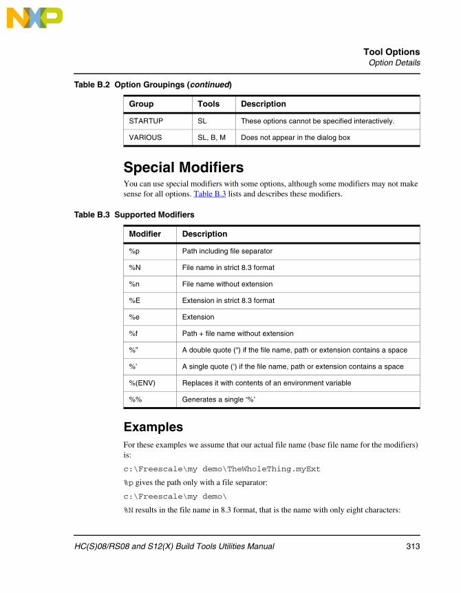
Tool OptionsOption Details
Special ModifiersYou can use special modifiers with some options, although some modifiers may not make sense for all options. Table B.3 lists and describes these modifiers.
ExamplesFor these examples we assume that our actual file name (base file name for the modifiers) is:
c:\Freescale\my demo\TheWholeThing.myExt
%p gives the path only with a file separator:
c:\Freescale\my demo\
%N results in the file name in 8.3 format, that is the name with only eight characters:
STARTUP SL These options cannot be specified interactively.
VARIOUS SL, B, M Does not appear in the dialog box
Table B.3 Supported Modifiers
Modifier Description
%p Path including file separator
%N File name in strict 8.3 format
%n File name without extension
%E Extension in strict 8.3 format
%e Extension
%f Path + file name without extension
%” A double quote (“) if the file name, path or extension contains a space
%’ A single quote (‘) if the file name, path or extension contains a space
%(ENV) Replaces it with contents of an environment variable
%% Generates a single ‘%’
Table B.2 Option Groupings (continued)
Group Tools Description
313HC(S)08/RS08 and S12(X) Build Tools Utilities Manual

Tool OptionsOption Details
TheWhole
%n returns just the file name without extension:
TheWholeThing
%E gives the extension in 8.3 format, that is, the extension with only three characters:
myE
%e is used for the whole extension:
myExt
%f gives the path plus the file name:
c:\Freescale\my demo\TheWholeThing
Because the path contains a space, using %” or %’ is recommended: Thus %”%f%” gives:
c:\Freescale\my demo\TheWholeThing
where %’%f%’ gives:
‘c:\Freescale\my demo\TheWholeThing’
When using %(envVariable) an environment variable may be used too. A file separator after %(envVariable) is ignored if the environment variable is empty or does not exist. For example, $(TEXTPATH)\myfile.txt is replaced with:
c:\Freescale\txt\myfile.txt
if TEXTPATH is set to:
TEXTPATH=c:\Freescale\txt
But is set to:
myfile.txt
if TEXTPATH does not exist or is empty.
%% may be used to print a percent sign. %e%% gives:
myExt%
-A: Print Full Listing (Decoder)
Group
OUTPUT
Syntax
-A
314 HC(S)08/RS08 and S12(X) Build Tools Utilities Manual

Tool OptionsOption Details
Arguments
None
File Format
Only Freescale. ELF Object files are not affected by this option.
Description
Prints a listing with the header information of the object file.
Example
Listing with command line fibo.o -A:
*** Header information ***Program Version 2700Format Version 2File Id 129flags 0processor family 11processor type 1Unitname fibo.absUsername PFRProgram time string Feb 25 1998Creation time string Wed Feb 25 11:43:22 1998CopyRight
*** Directory information for Absfile***Is romlib? 0
Init start:end 32774:32774Code beg:end 32768:32939Data beg:end 384:4096Total number of objects 7
At address: 8000 code size: 4000008000 1410 ORCC #16.........
315HC(S)08/RS08 and S12(X) Build Tools Utilities Manual

Tool OptionsOption Details
-A: Warning for Missing .DEF File (Maker)
Group
MODULA-2
Syntax
-A
Arguments
None
Description
Invokes a warning for a missing .DEF file and affects only the processing of Modula-2 makefiles.
Example
maker test.mod -M -A
-Add: Additional Object/Library File
Group
INPUT
Syntax
-Add <FileList>
Arguments
<FileList>: Names of an additional object files or libraries.
Description
Use this option to add additional files to a project without modifying the link parameter file.
If you intend to specify all binary files using the -Add command line option, then you must include an empty NAMES block (just NAMES END) in the link parameter file.
316 HC(S)08/RS08 and S12(X) Build Tools Utilities Manual

Tool OptionsOption Details
SmartLinker links object files added with this option before linking the object files specified in the NAMES block.
Example
To specify more than one file either use several -Add options:
linker.exe demo.prm -addFileA.o -addFileB.o
Or use braces to bind the list to the -Add option:
linker.exe demo.prm -add(FileA.o FileB.o)
Use braces together with double quotes to add a file in which the name contains spaces:
linker.exe demo.prm -add(“File A.o” “File B.o”)
linker.exe fibo.prm -addfibo1.o -addfibo2.o
This example links the additional object files fibo1.o and fibo2.o with the fibo application.
See also
NAMES: List Files Building the Application.
NOTE To turn off smart linking for the additional object file, use a + sign immediately behind the filename.
-Alloc: Allocation Over Segment Boundaries (ELF)
Group
OPTIMIZATION
Syntax
-Alloc ( First | Next | Change )
Arguments
First : Use first free location
Next : Always use next segment
Change : Check when segment changes only
317HC(S)08/RS08 and S12(X) Build Tools Utilities Manual

Tool OptionsOption Details
Default
-AllocNext
Description
The linker supports allocating objects from one ELF section into different segments. This option controls where space for the next object is allocated as soon as the first segment is full.
When you use -AllocNext, the linker always takes the next segment as soon as the current segment is full. Gaps resulting from this process are not used later. With the Next argument, the allocation order corresponds to the definition order in the object files. Objects defined first in a source file are allocated before objects defined later.
When you use -AllocFirst, the linker checks space requirements for every object. If the object fits into a previously used, partially filled segment, the linker uses that space. -AllocFirst does not maintain the definition order.
When you use -AllocChange, the linker checks space requirements only when the object does not fit into the current segment. If the object fits into a previously used, partially filled segment, the linker uses that space. -AllocChange does not maintain the definition order, but uses fewer different ranges than -AllocFirst.
NOTE This option has no effect in the Freescale format. In the Freescale format, the linker always uses the -AllocNext strategy. The linker does not maintain allocation order for small variables.
NOTE This option has no effect if sections are not split into segments. Then all strategies behave identically.
NOTE Some compilers perform code optimization in the assumption that the definition order is maintained in the memory. Such code is not split into multiple segments so no problems result from using this option.
Example
Objects: AAAA BB CCC D EEE FFFFF
Segments: “---” “-------” “------------”
AllocNext: “---” “AAAABB-” “CCCDEEEFFFFF”
AllocChange:“CCC” “AAAABBD” “EEEFFFFF----”
AllocFirst: “BBD” “AAAACCC” “EEEFFFFF----”
318 HC(S)08/RS08 and S12(X) Build Tools Utilities Manual

Tool OptionsOption Details
In this example, objects A (size 4 bytes), B (size 2 bytes), and F (size 5 bytes) must be allocated into three segments of size 3, 7 and 12 bytes. Because object A does not fit into the first segment, -AllocNext does not use this space at all. The two other strategies fill this space later. Only -AllocNext maintains object order.
-AsROMLib: Link as ROM Library
Group
OUTPUT
Syntax
-AsROMLib
Arguments
<FileList>: Names of an additional object files or libraries.
Description
Set -AsROMLib to link the application as a ROM library. This option has the same effect as specifying AS ROM_LIB in the linker parameter file.
Example
linker.exe myROMlib.prm -AsROMLib
-B: Generate S-Record file (SmartLinker)
Group
OUTPUT
Syntax
-B
Arguments
None
319HC(S)08/RS08 and S12(X) Build Tools Utilities Manual

Tool OptionsOption Details
Default
Disabled
Description
Setting this option tells the linker to generate an S-record file in addition to an absolute file. The name of the S-record file is the same as the name of the .abs file, except that the extension .SX is used. The default.env variable SRECORD may specify an alternative extension.
Example
LINKOPTIONS=-B
-C: Write Disassembly Listing with Source Code (Decoder)
Group
OUTPUT
Syntax
-C
Arguments
None
Default
None
File Format
Only Freescale. (ELF Object files are not affected by this option.)
Description
This option setting is default for the Freescale object files as input. When this option is specified, the Decoder decoding Freescale object files writes the source code within the disassembly listing.
Example
Listing with command line fibo.o -C (code depends on target): 8: unsigned int Fibonacci(unsigned int n)
320 HC(S)08/RS08 and S12(X) Build Tools Utilities Manual

Tool OptionsOption Details
9: { 10: unsigned fib1, fib2, fibo; 11: int i; 12: 00000000 3B PSHD 00000001 3B PSHD 13: fib1 = 0;00000002 C7 CLRB 00000003 87 CLRA 14: fib2 = 1;00000004 52 INCB 00000005 6C82 STD 2,SP 15: fibo = n;00000007 EE80 LDX 0,SP 16: i = 2; .................
-C: Ignore Case (Maker)
Group
INPUT
Syntax
-C
Arguments
None
Description
The make utility has default case sensitivity. Use this option to disable case sensitivity and treat lowercase characters the same as uppercase characters.
Example
maker test.mak -o
In the file test.mak:
OBJECTFILES = startup.o fibo.o
makeAll: $(ObjectFiles)
321HC(S)08/RS08 and S12(X) Build Tools Utilities Manual

Tool OptionsOption Details
This line with -c is equivalent to:
makeAll: $(OBJECTFILES)
-CAllocUnusedOverlap: Allocate Unreferenced Overlap Variables
(Freescale)
Group
OPTIMIZATION
Syntax
-CAllocUnusedOverlap
Arguments
None
Description
When Smart Linking is switched off, defined but unreferenced overlapped variables are not allocated by default. Such variables do not belong to a specific function, therefore they cannot be allocated overlapped with other variables.
This option only changes the behavior of variables in the special _OVERLAP segment. This segment is used only to allocate parameters and local variables for processors which do not have a stack. Not allocating an unreferenced overlap variable is similar to not allocating a variable on the stack for other processors. If you use this stack analogy, then allocating such variables this way corresponds to allocating unreferenced stack variables in global memory.
This option allows allocation of all defined objects. Using this option is not recommended.
Example
LINKOPTIONS=-CAllocUnusedOverlap
-Ci: Link Case Insensitive
Group
INPUT
322 HC(S)08/RS08 and S12(X) Build Tools Utilities Manual

Tool OptionsOption Details
Syntax
-Ci
Arguments
None
Description
With this option, the linker ignores object name capitalization.
This option supports case-insensitive linking of assembly modules. Since all identifiers are linked case insensitive, this also affects C or C++ modules.
NOTE This option can cause severe problems when combined with the name mangling of C++. Do not use this option with C++.
This option only affects the comparison of names of linked objects. Section names or the parsing of the link parameter file are unaffected. They remain case sensitive.
Example
void Tim(void);
void main(void) {
tim(); /* with -ci this call is resolved to Tim */
}
The linker matches the tim and Tim identifiers at link time. However, for the compiler these are still two separate objects and therefore the code above issues an “implicit parameter declaration” warning.
-Cmd: Libmaker Commands
Group
OUTPUT
Syntax
“-Cmd” "“" <commands> "“").
Arguments
<commands>: libmaker commands, separated by semicolon.
323HC(S)08/RS08 and S12(X) Build Tools Utilities Manual

Tool OptionsOption Details
Default
None.
Description
You can either run a libmaker command file (preceded by ‘@’), or use the -Cmd command on the command line to run libmaker commands. Alternatively, you can use the command without the ‘+’ operator as well:
-Cmd”a.o b.o c.o = d.lib”
Instead of “..” to wrap around the command string, you can use as well:
-Cmd(a.o b.o c.o = d.lib)
-Cmd[a.o b.o c.o = d.lib]
-Cmd{a.o b.o c.o = d.lib}
-Cmd’a.o b.o c.o = d.lib’
If your file names have spaces or operator characters in the file name, you need to use double quotes for the file name:
-Cmd(a.o “my b.o” “c-c.o” = d.lib)
You still can use double quotes for the -Cmd option, but in such a case you need to double-double quote files names in double quotes:
-Cmd”a.o ““my b.o”” ““c-c.o”” = d.lib”
Example
-Cmd”a.o + b.o = c.lib”
See also
-Mar: Freescale Archive Commands (Libmaker)
-Cocc: Optimize Common Code (ELF)
Group
OPTIMIZATION
Syntax
-Cocc [ = [ D ] [ C ]]
324 HC(S)08/RS08 and S12(X) Build Tools Utilities Manual

Tool OptionsOption Details
Arguments
D : optimize Data (constants and strings).
C : optimize Code
Description
This option defines the default when optimizing constants and cod. The commands DO_OVERLAP_CONSTS and DO_NOT_OVERLAP_CONSTS take precedence over the option.
Example
printf(“Hello World\n”); printf(“\n”);
-Cocc allocates the string “\n” inside of the string “Hello World\n”.
-CRam: Allocate Non-specified Constant Segments in RAM (ELF)
Group
OPTIMIZATION
Syntax
-CRam
Arguments
None
Description
This option allocates constant data segments not explicitly allocated in a READ_ONLY segment in the default READ_WRITE segment.
This was the default for old versions of the linker, so this option provides a compatible behavior with old linker versions.
Example
When C source files are compiled with -CC, the constants are put into the ROM_VAR segment. If the ROM_VAR segment is not mentioned in the prm file, then without this option, these constants are allocated in DEFAULT_ROM. With this option they are allocated in DEFAULT_RAM.
325HC(S)08/RS08 and S12(X) Build Tools Utilities Manual

Tool OptionsOption Details
-D: Display Dialog Box (Burner)
Group
VARIOUS
Syntax
“-D”.
Arguments
None
Default
None
Description
This option displays the Burner dialog box. This interface, with its three tabs, allows you to launch the burner from a make file and await user input.
Figure B.1 Burner Dialog Window Input/Output Tab
Example
burner.exe -D
-D: Decode DWARF Sections (Decoder)
Group
OUTPUT
Syntax
-D
Arguments
None
Default
Disabled
326 HC(S)08/RS08 and S12(X) Build Tools Utilities Manual

Tool OptionsOption Details
File Format
Only ELF. Freescale object files are not affected by this option.
Description
When you specify this option, DWARF section information is also written to the listing file. Decoding from the DWARF section inserts this information in the listing file. See the following listings for more information.
Listing B.1 Source/code reference information
.debug_line 0x4 Version 2 0x6 PrologLen 122l 0xa MinInstrLen 1c 0xb DefIsStmt 0c 0xc LineBase 0c 0xd LineRange 4c 0xe DW2L_OpcodeBase 9c 0xf Opcodelengths : 0c 1c 1c 1c 1c 0c 0c 0c 1c
Includedir : 0x19 File 1: Y:\DEMO\WAVE12C\fibo.c, 0, 0, 0 0x33 File 2: y:\LIB\ELF12C\hidef.h, 0, 0, 0 0x4c File 3: y:\LIB\ELF12C\default.sgm, 0, 0, 0 0x69 File 4: y:\LIB\ELF12C\stddef.h, 0, 0, 0 0x84 Set Addr 867(2151): ADDR FILE LINE COL STMT BASIC 0x8b set column : 867 1 1 14 0 0 0x8d advance line : 867 1 8 14 0 0 0x8f negate stmt : 867 1 8 14 1 0 0x90 negate stmt : 867 1 8 14 0 0...
Listing B.2 Argument location for local variables information
.debug_loc 0 Start 867, End 869 (2)DW_OP_breg15 0(0) 0xc Start 869, End 86a (2)DW_OP_breg15 8(8) 0x18 Start 86a, End 895 (2)DW_OP_breg15 10(a) 0x24 Start 895, End 896 (2)DW_OP_breg15 0(0) 0x30 0, 0 : end of location-list
Listing B.3 Symbol Debug information
DWARF: .debug_info (1053) [0x734]
327HC(S)08/RS08 and S12(X) Build Tools Utilities Manual

Tool OptionsOption Details
Compi.Unit Header: size 304, version 2, abbrev 0, addrsize 4 0xb Abbrevation 128 ,compile_unit 0xd name string fibo.c 0x14 producer string FREESCALE 0x1b comp_dir string Y:\DEMO\WAVE12C 0x2b language udata DW_LANG_C89 0x2c stmt_list data4 0(0)
Listing B.4 Frame Debug Information
.debug_frame 0 CIE Information 0x8 Version 1 0x9 Augmentor Freescale CFA 1.0 0x18 CodeAlign: 1, DataAlign: 1, ReturnAddr-Column: 18 0x1b instruction PC FP(Reg) R[ 0] R[ 1] R[ 2] R[ 3] R[ 4] R[ 5] R[ 6] R[ 7] R[ 8] R[ 9] R[10] R[11] R[12] R[13] R[14] R[15] R[16] R[17] R[18] R[19] R[20] R[21] R[22] R[23] R[24] R[25] R[26] R[27] R[28] R[29] R[30] R[31] 0x1b start-values 84d: 0( 15) 0x1b Def CFA Register reg: 15, 0x1d Def CFA Offset ofs: 0 0x1f Offset: reg 18, Ofs: 0 0x21 Undefined reg: 0 0x23 Undefined reg: 1
NOTE Specify the -E option when the -D option is activated.
-D: Define a Macro (Maker)
Group
INPUT
Syntax
-D <macroname> = <value>
Arguments
The macro definition string “<macroname> = <value>”.
328 HC(S)08/RS08 and S12(X) Build Tools Utilities Manual

Tool OptionsOption Details
Description
This option defines command-line macros. Command-line macros define macros and arguments for the make file. A macro defined this way has a higher priority than a macro defined in the makefile. Because you separate the arguments in the command line with spaces, you cannot place spaces in a command-line macro.
Examples
-dCOMP=chc12.exe
-dCOMP=chc12.exe -Li -Wi
-d[MAKE=Maker.exe -s -d(COMP=$(COMP))]
-Disp: Display Mode (Maker)
Group
OUTPUT
Syntax
-Disp
Arguments
None
Description
Maker echoes executing commands without calling them. Use this mode to check the dependency graph without affecting any files.
Example
maker test.mak -disp
-Dist: Enable Distribution Optimization (ELF) (SmartLinker)
Group
OPTIMIZATIONS
329HC(S)08/RS08 and S12(X) Build Tools Utilities Manual

Tool OptionsOption Details
Syntax
-Dist
Arguments
None
Description
This option enables the linker optimizer. Instead of a link, the linker generates a distribution file which contains an optimized distribution.
-DistFile: Specify Distribution File Name (ELF) (SmartLinker)
Group
OPTIMIZATIONS
Syntax
-DistFile <file name>
Arguments
<file name>: Name of the distribution file.
Default
distr.inc
Description
Enable this option to specify the name of the distribution file. The distribution file lists all distributed functions and specifies how the compiler reallocates them.
Example
LINKOPTIONS=-DistFileMyFile
-DistInfo: Generate Distribution Information File (ELF)
330 HC(S)08/RS08 and S12(X) Build Tools Utilities Manual

Tool OptionsOption Details
(SmartLinker)
Group
OPTIMIZATIONS
Syntax
-DistInfo <file name>
Arguments
<file name>: Name of the information file.
Default
distr.txt
Description
Using this option, the optimizer generates a distribution information file containing a list of all sections and their functions. Available function information includes the old size, optimized size, and new calling convention.
Example
LINKOPTIONS=-DistInfoMyInfoFile
-DistOpti: Choose Optimizing Method (ELF) (SmartLinker)
Group
OPTIMIZATIONS
Syntax
-DistOpti ( FillBanks | CodeSize )
Arguments
FillBanks : Priority is to fill the banks.
CodeSize : Priority is to minimize the code size.
Default
-DistOptiFillBanks
331HC(S)08/RS08 and S12(X) Build Tools Utilities Manual

Tool OptionsOption Details
Description
Enable this option to choose the optimizing method. With the FillBanks argument the linker minimizes the free space in every bank. FillBanks is most effective for functions using the near calling convention. Use the CodeSize argument to minimize code when free space within the banks is no concern.
Example
LINKOPTIONS=-DistOptiFillBanks
-DistSeg: Specify Distribution Segment Name (ELF) (SmartLinker)
OPTIMIZATIONS
Syntax
-DistSeg <segment name>
Arguments
<segment name>: Name of the distribution segment.
Default
DISTRIBUTE
Description
Use this option to specify the name of the distribution segment.
Example
LINKOPTIONS=-DistSegMyDistributionSegment
-E: Define Application Entry Point (ELF) (SmartLinker)
Group
INPUT
Syntax
-E= <FunctionName>
332 HC(S)08/RS08 and S12(X) Build Tools Utilities Manual

Tool OptionsOption Details
Arguments
<FunctionName> : Name of the function considered to be the entry point in the application.
Description
This option specifies the name of the application entry point.
The symbol specified must be externally visible (not defined as static in an ANSI-C source file or XREFed in an assembly source file).
Example
LINKOPTIONS=-E=entry
This is the same as using the command:
INIT entry
in the prm file.
-E: Decode ELF sections (Decoder)
Group
OUTPUT
Syntax
-E
Arguments
None
File Format
Only ELF. Freescale Object files are not affected by this option.
Description
When you specify this option, ELF section information is also written to the listing file. Decoding from the ELF section inserts the following information in the listing file:
Listing B.5 ELF Header Information
File: Y:\DEMO\WAVE12C\fibo.absIdent: ELF with 32-bit objects, MSB encoding, Version 1
333HC(S)08/RS08 and S12(X) Build Tools Utilities Manual

Tool OptionsOption Details
Type: Executable file, Machine: Freescale HC12, Vers: 1Entry point: 83DElf flags: 0ElfHSiz: 34ProgHOff: 34, ProgHSi: 20, ProgHNu: 6SectHOff: E3A, SectHSi: 28, SectHNu: 19, SectHSI: 18
Usually the ELF Program header Table is available only for absolute files.
Listing B.6 ELF Program header Table Information
PROGRAM HEADER TABLE - 6 ItemsStarts at: 34, Size of an entry: 20, Ends at: F4 NO TYPE OFFSET SIZE VIRTADDR PHYADDR MEMSIZE FLAGS ALIGNMNT 0 - PT_PHDR 34 C0 1 - PT_LOAD F4 0 0 800 4 6 0 2 - PT_LOAD F4 AE 0 810 AE 1 0
Listing B.7 ELF Section Header Table Information
SECTION HEADER TABLE - 19 ItemsStarts at: E3A, Size of an entry: 28, Ends at: 1132String table is in section: 12 NO NAME TYPE FLAGS OFFSET SIZE ADDR ALI RECS LINK INFO 0- NULL 0 0 0 0 0 0 0 1-.common NOBITS WA F4 4 800 0 0 0 0 2-.init PROGBITS AX F4 3D 810 0 0 0 0 3-.startData PROGBITS AX 131 1A 84D 0 0 0 0 4-.text PROGBITS AX 14B 55 867 0 0 0 0 5-.copy PROGBITS AX 1A0 2 8BC 0 0 0 0 6-.stack NOBITS WA 1A2 100 B00 0 0 0 0 7-.vectSeg0_vect PROGBITS AX 1A2 2 FFFE 0 0 0 0
Listing B.8 Symbol Table Information
SYMBOL TABLE: .symtab - 13 ItemsStarts at: 1A4, Size of an entry: 10, Ends at: 274String table is in section: 9First global symbol is in entry no.: 8 NO NAME VALUE SIZE BIND TYPE SECT 0- 0 0 LOCAL NOTYPE 1- 0 0 LOCAL SECTION 1 2- 0 0 LOCAL SECTION 2 3-Init 810 2D LOCAL FUNC 2
334 HC(S)08/RS08 and S12(X) Build Tools Utilities Manual

Tool OptionsOption Details
4- 0 0 LOCAL SECTION 3 5- 0 0 LOCAL SECTION 4
Listing B.9 Relocation Section Information
RELOCATION TABLE RELA: .rela.init - 1 ItemsStarts at: 2AA, Size of an entry: C, Ends at: 2B6Symbol table is in section: 8Binary code/data is in section: 2 NO OFFSET SYMNDX TYP ADDEND SYMNAME 0 - 2163 873 3 3 4107 Init
Listing B.10 Hexadecimal dump from all sections defined in the binary file
HEXDUMP OF: .init FROM 244 TO 305 SIZE 61 (0X3D)OFFSET +0 +1 +2 +3 +4 +5 +6 +7 : +8 +9 +A +B +C +D +E +F ASCII DATA000000 FE 08 55 FD 08 53 27 10 : 35 ED 31 EC 31 69 70 83 ...U ... S'.5.1.1ip.000010 00 01 26 F9 31 03 26 F0 : FE 08 57 EC 31 27 0D ED .&.1.&... W.1'..000020 31 18 0A 30 70 83 00 01 : 26 F7 20 EF 3D FC 08 4D 1..0p. .&. .=..M000030 26 03 FF 08 51 07 C9 15 : FB 00 04 20 F0 &...Q.... . .
-E: Unknown Macros as Empty Strings (Maker)
Group
INPUT
Syntax
-E
Arguments
None
Description
This macro discards errors for unknown macros referenced in the makefile. Maker substitutes an unknown macro with an empty string.
335HC(S)08/RS08 and S12(X) Build Tools Utilities Manual

Tool OptionsOption Details
Example
maker -m test.mod -e
-Ed: Dump ELF Sections in LST File (Decoder)
Group
OUTPUT
Syntax
-Ed
Arguments
None
Default
None
File Format
Only ELF. Freescale object files are not affected by this option.
Description
This option generates a HEX dump of all ELF sections.
NOTE The related option -E shows the information contained in ELF sections in a more readable form.
-Env: Set Environment Variable
Group
HOST
Syntax
-Env <Environment Variable> = <Variable Setting>
336 HC(S)08/RS08 and S12(X) Build Tools Utilities Manual

Tool OptionsOption Details
Arguments
<Environment Variable> : Environment variable to be set.
<Variable Setting> : Setting of the environment variable.
Description
This option sets an environment variable. The environment variable may be used in the maker or to overwrite system environment variables.
Example
-EnvOBJPATH=\sources\obj
This is the same as:
OBJPATH=\sources\obj
in default.env
To use an environment variable with file names that contain spaces, use the following syntax:
-Env”OBJPATH=program files”
-F: Execute Command File (Burner)
Group
INPUT
Syntax
“-F=” <fileName>.
Arguments
<fileName>: Batch Burner command file to be executed.
Default
None
Description
This option causes the Burner to execute a Batch Burner command file (usual extension is .bbl).
337HC(S)08/RS08 and S12(X) Build Tools Utilities Manual

Tool OptionsOption Details
Example
-F=fibo.bbl
-F: Object File Format (Decoder)
Group
INPUT
Syntax
-F ( A | E | I | H | S )
Arguments
None
Default
-FA
Description
The decoder is able to decode different object file formats. This option defines which object file format should be decoded:
-FA : the decoder determines the object file format automatically.
-FE : this can be overridden and only ELF files are correctly decoded.
-FH : only Freescale files are decoded.
-FS : only S-Record files can be decoded.
-FI : Intel Hex files can be decoded.
NOTE This option defines the Object File Format, which also defines the format of absolute files and libraries. It does not only affect object files. Many other options only effect a specific object file format. See the corresponding option for details.
NOTE To decode an S-Record or Intel Hex file, use the option -Proc: Set Processor (Decoder) to specify the processor.
338 HC(S)08/RS08 and S12(X) Build Tools Utilities Manual

Tool OptionsOption Details
-FA, -FE, -FH -F6: Object File Format (SmartLinker)
Group
INPUT
Syntax
-F ( A | E | H | 6 )
Arguments
none
Default
-FA
Description
Using this option the linker is able to link different object file formats. This option defines which object file format the linker uses:
• Using -FA, the linker determines the object file format automatically.
• Using -FE, the linker recognizes only ELF files correctly.
• Using -FH, the linker recognizes only Freescale files correctly.
• Using -F6, the linker produces a V2.6 Freescale absolute file.
NOTE It is not possible to build an application consisting of both Freescale and ELF files. Either all files must be in ELF format or all files must be in Freescale format.The format of the generated absolute file is the same as the format of the object files. ELF object files generate ELF absolute files and Freescale object files generate Freescale absolute files.
-H: Prints the List of All Available Options (Short Help)
Group
OUTPUT, VARIOUS
339HC(S)08/RS08 and S12(X) Build Tools Utilities Manual

Tool OptionsOption Details
Syntax
-H
Arguments
None
Description
This option prints the list of all options, sorted by Group. Options in the same group are sorted alphabetically. No other option or source file should be specified with the -H option.
Example
Linker option output of -H:
-F Object File Format-Fh Freescale-FEo Compatible ELF (DWARF 1.1/DWARF 2.0)-Fa Automatic Detection-F6 Freescale V2.6
Burner option output of -H:
...VARIOUS:-H Prints this list of options-V Prints the Compiler version...
Libmaker option output of -H:
HOST:-Env Set environment variable-View Application Standard Occurrence
-ViewWindow Window-ViewMin Min-ViewMax Max-ViewHidden Hidden
340 HC(S)08/RS08 and S12(X) Build Tools Utilities Manual

Tool OptionsOption Details
-I: Ignore Exit Codes (Maker)
Group
OUTPUT
Syntax
-I
Arguments
None
Description
This option lets Maker ignore exit codes of the called programs. Maker continues processing even if the called application reports a fatal error or creation of the corresponding process fails. Use this option for testing purposes, where Maker resolves only the dependencies of a make file.
Example
maker -m test.mod -i
-L: Add a Path to Search Path (ELF) (SmartLinker)
Group
INPUT
Syntax
-L <Directory>
Arguments
<Directory> : Name of an additional search directory for object files.
Description
With this option, the ELF part of this linker searches object files first in all paths given with this option before considering the usual environment variables.
341HC(S)08/RS08 and S12(X) Build Tools Utilities Manual

Tool OptionsOption Details
Example
LINKOPTIONS=-Lc:\freescale\obj
See also
OBJPATH: Object File Path
-L: Produce Inline Assembly File (Decoder)
Group
OUTPUT
Syntax
-L
Arguments
None
File Format
Only Freescale. ELF Object files are not affected by this option.
Description
The output listing is an inline assembly file without additional information, but in C comments.
Example
Part of Listing with command line fibo.o -L (code depends on target):
unsigned int Fibonacci(unsigned int n){ unsigned fib1, fib2, fibo; int i; asm{ CLRB CLRA INCB STD 2,SP LDX 0,SP LDY #2 SEX A,D
342 HC(S)08/RS08 and S12(X) Build Tools Utilities Manual

Tool OptionsOption Details
BRA LBL25 LBL16: ADDD 2,SP ... RTS } }
-L: List Modules (Maker)
Group
MODULA-2
Syntax
-L <listfile>
Arguments
File name of the generated listing file
Description
This option lists compiled files in build order in the file specified in the argument <listfile>. This option affects only the processing of Modula-2 makefiles.
Example
maker -m test.mod -ltest.lst
-LibFile
Specifies the name of the file that contains linker-generated library information.
Syntax
-LibFile<filename>
Arguments
<filename>: Name of the file that has the information about libraries and startup(optional) to be used in second link step.
343HC(S)08/RS08 and S12(X) Build Tools Utilities Manual

Tool OptionsOption Details
Description
When this option is enabled,linker generates file<filename> which has information about the current libraries and also about the files with which they should be replaced with.
-LibOptions
Enables library information generation.
Syntax
-LibOptions
Arguments
None
Description
When this option is enabled,linker generates file(default libFile.txt ) which has information about the current library and the startup file and also about the files with which they should be replaced with.
-Lic: Print License Information
Group
Various
Syntax
-Lic
Arguments
None
Description
This options shows the current state of the license information. When no full license is available, the tool runs in demo mode. This information is also displayed in the About box.
344 HC(S)08/RS08 and S12(X) Build Tools Utilities Manual

Tool OptionsOption Details
Example
-Lic
-LicA: License Information About Every Feature in Directory
Group
Various
Syntax
-LicA
Arguments
None
Description
The -LicA option prints the license information of every tool or dll in the directory where the executable is located. Because the option analyzes every single file in the directory, this may take a long time.
Example
-LicA
-LicBorrow: Borrow License Feature
Group
HOST
Syntax
-LicBorrow <feature>[ ; <version>] : <Date>
Arguments
<feature>: the feature name to be borrowed (e.g. HI100100).
<version>: optional version of the feature to be borrowed (e.g. 3.000).
<date>: date with optional time until when the feature shall be borrowed (e.g. 15-Mar-2007:18:35).
345HC(S)08/RS08 and S12(X) Build Tools Utilities Manual

Tool OptionsOption Details
Description
This option allows you to borrow a license feature until a given date/time. Borrowing allows you to use a floating license even if disconnected from the floating license server.
You need to specify the feature name and the date you will return the feature. If the feature you want to borrow is a feature belonging to the tool where you use this option, then you do not need to specify the feature version (because the tool knows the version). To borrow any feature not belonging to the tool, you need to specify the feature version. You can check the status of currently borrowed features in the tool About box.
You can borrow features only if you have a floating license and borrowing is enabled on your floating license. See the FLEXlm documentation for details on borrowing.
Example
-LicBorrowHI100100;3.000:12-Mar-2004:18:25
-LicWait: Wait for Floating License from Floating License Server
Group
HOST
Syntax
-LicWait
Arguments
None
Description
By default, if a license is not available from the floating license server, then the application returns immediately. When you set -LicWait, the application waits until a license is available from the floating license server. This is called blocking.
Example
-LicWait
346 HC(S)08/RS08 and S12(X) Build Tools Utilities Manual

Tool OptionsOption Details
-M: Generate Map File (SmartLinker)
Group
OUTPUT
Syntax
-M
Arguments
None
Description
This option forces map file generation after a successful linking session.
Example
LINKOPTIONS=-M
This is the same as using the command:
MAPFILE ALL
in the prm file.
See also
MAPFILE: Configure Map File Content
-M: Produce Make File (Maker)
Group
MODULA-2
Syntax
-M [ <makefile> ]
Arguments
File name of the generated makefile
347HC(S)08/RS08 and S12(X) Build Tools Utilities Manual

Tool OptionsOption Details
Description
This option generates a makefile. If this option immediately follows a file name, Maker writes the makefile to that file; otherwise, the makefile has the same name as the main module, but with suffix .MAK. This makefile uses macros by referencing above environment variables.
Example
maker test.mod -m test.mak
-Mar: Freescale Archive Commands (Libmaker)
Group
OUTPUT
Syntax
“-Mar” “““ <library> [<member>] “““.
Arguments
<library>: name of the library.
<member>: list of members for the library to be added.
Default
None
Description
This command provides a more ‘ar’ (archive) like way to create a library out of object files. Instead of the following:
-Cmd”a.o b.o c.o = d.lib”
You can use:
-Mar”d.lib a.o b.o c.o”
Unlike the -Cmd command, this command performs no operator processing (‘+’/’-’), which makes it easier to deal with file names containing operator characters.
Example
-Mar”c.lib a.o b.o”
348 HC(S)08/RS08 and S12(X) Build Tools Utilities Manual

Tool OptionsOption Details
See also
-Cmd: Libmaker Commands
-MkAll: Make Always (Maker)
Group
INPUT
Syntax
-MkAll
Arguments
None
Description
This option skips Maker time-checking. Maker rebuilds up-to-date files. Use this option for updating the application after a change not covered by makefile dependencies.
Example
maker test.mak -mkall
-N: Display Notify Box
Group
MESSAGE
Syntax
-N
Arguments
None
349HC(S)08/RS08 and S12(X) Build Tools Utilities Manual

Tool OptionsOption Details
Description
This option makes the tool display an alert box if an error occurs during linking. This is useful when running a makefile since the linker waits for the user to acknowledge the message, thus suspending makefile processing. (The N stands for Notify.) This option is
Use this feature for halting and aborting a build using the Make Utility.
Example
SmartLinker: LINKOPTIONS=-N
Burner: -Fnofile -N
If an error occurs during linking, an error dialog box opens.
NOTE This option is only present on the PC version of the tools. The UNIX version does not accept -n as an option string.
350 HC(S)08/RS08 and S12(X) Build Tools Utilities Manual

Tool OptionsOption Details
-NoBeep: No Beep in Case of an Error
Group
MESSAGE
Syntax
-NoBeep
Arguments
None
Description
Normally there is a ‘beep’ notification at the end of processing if an error occurs. To silence this error behavior, use this option to switch off the beep.
Example
None
-NoCapture: Do Not Redirect stdout of Called Processes (Maker)
Group
OUTPUT
Syntax
-NoCapture
Arguments
None
Description
Maker’s default behavior is to redirect from stdout the output text of called applications. Use this option to prevent redirection and text output for errors. This option affects only text output, since Maker does not detect the called application issuing the error.
351HC(S)08/RS08 and S12(X) Build Tools Utilities Manual

Tool OptionsOption Details
This option accelerates the make process and older applications that do not support output. Using this option is equivalent to placing “*” at the start of every command line.
Example
maker test.mak -NoCapture
-NoEnv: Do Not Use Environment
Group
Startup. (This option cannot be specified interactively.)
Syntax
-NoEnv
Arguments
None
Description
This option can be specified only while starting the application at the command line. It cannot be specified in any other circumstance, including the default.env file, and the command line.
When this option is given, the application does not use any environment (default.env, project.ini or tips file).
Example
linker.exe -NoEnv
See also
Environment Variables
352 HC(S)08/RS08 and S12(X) Build Tools Utilities Manual

Tool OptionsOption Details
-NoPath: Strip Path Info (Libmaker)
Group
OUTPUT
Syntax
“-NoPath”.
Arguments
None
Default
None
Description
Use this option to ignore path information in object files. This is useful if you want to move object files to another file location or hide your path structure.
Example
-NoPath
-NoSym: No Symbols in Disassembled Listing (Decoder)
Group
OUTPUT
Syntax
-NoSym
Arguments
None
Description
Prevents symbols from printing in the disassembled listing.
353HC(S)08/RS08 and S12(X) Build Tools Utilities Manual

Tool OptionsOption Details
NOTE In previous versions of the Decoder, this option was called -N. It was renamed because of a conflict with the common option -N, which was not present in previous versions. The option -NoSym has no effect when decoding .abs files. As the .abs file does not contain any relocation information, it is not possible to display symbol names in the disassembly listing.
Example
Part of Listing with command line fibo.o -NoSym.
DISASSEMBLY OF: '.text' FROM 531 TO 664 SIZE 133 (0X85)Source file: 'fibo.c' 19: unsigned int Fibonacci(unsigned int n)Fibonacci:00000000 1B98 LEAS -8,SP00000002 3B PSHD 24: fib1 = x[0] + f + g;00000003 FC0000 LDD $000000000006 F30000 ADDD $000000000009 F30000 ADDD $00000000000C 6C88 STD 8,SP 25: fib2 = x[1];0000000E FC0002 LDD $000200000011 6C84 STD 4,SP
-Ns: Configure S-Records (Burner)
Group
OUTPUT
Syntax
“-Ns” [“=” {“p” | “0” | “7” | “8” | “9”}].
Arguments“p”: no path in S0 record
“0”: no S0 record
“7”: no S7 record
“8”: no S8 record
“9”: no S9 record
354 HC(S)08/RS08 and S12(X) Build Tools Utilities Manual

Tool OptionsOption Details
Default
None
DescriptionUsually an S-Record file contains a S0-Record at the beginning that contains the name of the file and an S7, S8 or S9 record at the end, depending on the address size. For the S3 format, an S7 record is written at the end. For S2 format, an S8 record is written at the end. For the S1 format, an S9 record is written at the end.
This feature is useful for disabling some S-Record generation in case a non-standard S-Record file reader cannot read S0, S7, S8 or S9 records.
In case the option is specified without suboptions (only -Ns), no start (S0) and no end records (S7, S8 or S9) are generated.
The option -Ns=p removes the path (if present) from the file name in the S0 record.
Example
-Ns=0
See also:
SRECORD: S-Record Type
-O: Define Absolute File Name (SmartLinker)
Group
OUTPUT
Syntax
-O <FileName>
Arguments
<fileName>: Name of the absolute file which must be generated by the linking session.
Description
Use this option to define the name of the generated ABS file. If you are using the Linker with the CodeWarrior Development Studio, this option is automatically added to the command line passed to the linker. You can see this if you enable Display generated
355HC(S)08/RS08 and S12(X) Build Tools Utilities Manual

Tool OptionsOption Details
command lines in message window in the Linker preference panel in the CodeWarrior IDE.
No extension is added automatically. Specifying the option -otest generates a file named test. To get the usual .abs file extension, use -otest.abs.
Example
LINKOPTIONS=-Otest.abs
This is the same as using the command:
LINK test.abs
in the prm file,
See also
LINK: Specify Name of Output File
-O: Defines Listing File Name (Decoder)
Group
OUTPUT
Syntax
-O <FileName>
Arguments
<fileName>: Name of listing file that must be generated by the decoding session.
Default
None
Description
This option defines the name of the output file to be generated.
Example
-O=TEST.LST
The decoder generates a file named TEST.LST.
356 HC(S)08/RS08 and S12(X) Build Tools Utilities Manual

Tool OptionsOption Details
-O: Compile Only (Maker)
Group
MODULA-2
Syntax
-O
Arguments
None.
Example
maker test.mod -o
Description
Use this macro to have Maker perform only compile steps for a Modula-2 build. Maker does not call the linker. This option affects only Modula-2 makefile processing.
-OCopy: Optimize Copy Down (ELF) (SmartLinker)
Group
OPTIMIZATION
Syntax
-OCopy ( On | Off )
Arguments
On : Do the optimization.
Off: Optimization disabled.
Default
-OCopyOn
357HC(S)08/RS08 and S12(X) Build Tools Utilities Manual

Tool OptionsOption Details
Description
This optimization changes the copy-down structure to use as little space as possible.
The optimization assumes that the application performs both the zero out and the copy down step of the global initialization. If a value is set to zero by the zero out, then zero values are removed from the copy down information. The resulting initialization is not changed by this optimization if the default startup code is used.
This switch only has an effect in the ELF Format. The optimizations done in the Freescale format cannot be switched off.
Example
LINKOPTIONS=-OCopyOn
-Options
Enables compiler option generation. The generated options will be used for second step compilation.
Syntax
-Options
Arguments
None
Description
Linker generates a text file containing a compiler option for the second step (one of the following: -ConstQualiNear, -NonConstQualiNear, -Mb). The content of the file is appended to the compiler options for the second compilation step.
-OptionFile
Specifies the name of the file that contains the set of linker-generated compiler options.
Syntax
-OptionFile<filename>
358 HC(S)08/RS08 and S12(X) Build Tools Utilities Manual

Tool OptionsOption Details
Arguments
<filename> : Name of the option file.
Description
When this option is enabled, linker places the second step compiler options in the specified file<filename>.
-P2LibFile
Specifies the name of the library information file.
Syntax
-P2libFile<filename>
Arguments
<filename> Name of the library information file.
Description
When this option is enabled in second link step,linker reads file<filename> which has information about the libraries.
-Proc: Set Processor (Decoder)
Group
INPUT
Syntax
-Proc= <ProcessorName>[ : <Derivative>].
Arguments
<ProcessorName>: Name of a supported processor.
<DerivativeName>: Name of supported derivative.
Default
None
359HC(S)08/RS08 and S12(X) Build Tools Utilities Manual

Tool OptionsOption Details
Description
This option specifies which processor should be decoded. For object files, libraries and applications, the processor is usually detected automatically. For S-Record and Intel Hex files, however, the decoder cannot determine which CPU the code is for, and therefore the processor must be specified with this option to get a disassembly output. Without this option, only the structure of a S-Record file is decoded.
The following values are supported:
HC08, HC08:HCS08, HC11, HC12, HC12:CPU12, HC12:HCS12, HC12:HCS12X, HC16, M68k, MCORE, PPC, RS08, 8500, 8300, 8051 and XA
Example
decoder.exe fibo.s19 -proc=HC12
-Prod: Specify Project File at Startup (PC) (No d, no m)
Group
None. This option cannot be specified interactively.
Syntax
-Prod= <file>
Arguments
<file>: Name of a project or project directory.
Description
This option can only be specified while starting the linker at the command line. It cannot be specified in any other circumstances, including the default.env file, the command line, etc.
When you use this option, the linker opens the file as a configuration file. When <file> contains only a directory name, the linker appends the default name project.ini. When the loading fails, a message box appears.
Example
linker.exe -prod=project.ini
360 HC(S)08/RS08 and S12(X) Build Tools Utilities Manual

Tool OptionsOption Details
-ReadLibFile
Instructs the linker to read in the library information file that it generated in step one.
Syntax
-ReadLibFile
Arguments
None
Description
This option is passed in second link step. It tells the linker to read library information file(default libFile.txt).
-S: Do Not Generate DWARF Information (ELF) (SmartLinker)
Group
OUTPUT
Syntax
-S
Arguments
None
Description
This option disables the generation of DWARF sections in the absolute file to save memory space.
Example
LINKOPTIONS=-S
NOTE If the absolute file does not contain any DWARF information, you will not be able to debug it symbolically.
361HC(S)08/RS08 and S12(X) Build Tools Utilities Manual

Tool OptionsOption Details
-S: Silent Mode (Maker)
Group
OUTPUT
Syntax
-S
Arguments
None
Example
maker test.mod -s
Description
Maker does not echo executed commands. Use this option to examine only Maker messages or those of the called tools, where an otherwise long list of executed commands is inconvenient.
-SFixups: Creating Fixups (ELF) (SmartLinker)
Group
OUTPUT
Syntax
-SFixups
Arguments
None
Description
Usually, absolute files do not contain any fixups because all fixups are evaluated at link time. But with fixups, the decoder might symbolically decode the content in absolute files. Some debuggers do not load absolute files which contain fixups
362 HC(S)08/RS08 and S12(X) Build Tools Utilities Manual

Tool OptionsOption Details
because they assume that these fixups are not yet evaluated. But the fixups inserted with this option are actually already handled by this linker.
This option is included to ensure compatibility with previous linker versions.
Example
LINKOPTIONS=-SFixups
-StartUpInfo
Enables startup information generation.
Syntax
-StartUpInfo
Arguments
None
Description
The information about the current startup file and the replacement startup file will be added to the library file(default libFile.txt) and used during the second compile-link step.
-StatF: Specify Name of Statistic File (SmartLinker)
Group
OUTPUT
Syntax
-StatF= <fileName>
Arguments
<fileName>: Name for the file to be written.
Description
With this option set, the linker generates a statistic file. The statistic file reports each allocated object and its attributes. Every attribute is separated by a tab
363HC(S)08/RS08 and S12(X) Build Tools Utilities Manual

Tool OptionsOption Details
character, so it can be easily imported into a spreadsheet/database program for further processing.
Example
LINKOPTIONS=-StatF
-T: Show Cycle Count for Each Instruction (Decoder)
Group
OUTPUT
Syntax
-T
Arguments
None
Description
If you specify this option, each instruction line contains the count of cycles in ‘[‘,’]’ braces. The cycle count is written before the mnemonics of the instruction. Note that the cycle count display is not supported for all architectures.
Example
Part of Listing (HC12, ELF) with command line fibo.o -T:
DISASSEMBLY OF: '.text' FROM 531 TO 664 SIZE 133 (0X85)Source file: 'X:\CHC12E\DEMO\ELF12C\fibo.c' 19: unsigned int Fibonacci(unsigned int n)Fibonacci:00000000 1B98 [2] LEAS -8,SP00000002 3B [2] PSHD 24: fib1 = x[0] + f + g;00000003 FC0000 [3] LDD x00000006 F30000 [3] ADDD f00000009 F30000 [3] ADDD g0000000C 6C88 [2] STD 8,SP 25: fib2 = x[1];0000000E FC0002 [3] LDD x00000011 6C84 [2] STD 4,SP 26: fibo = 0;00000013 C7 [1] CLRB
364 HC(S)08/RS08 and S12(X) Build Tools Utilities Manual

Tool OptionsOption Details
00000014 87 [1] CLRA 00000015 6C86 [2] STD 6,SP 27: i = 2; 00000017 C602 [1] LDAB #200000019 6C82 [2] STD 2,SP
-V: Prints Tool Version
Group
OUTPUT
Syntax
-V
Arguments
None
Description
Prints the SmartLinker version and the project directory.
Use this option to determine the SmartLinker project directory.
Example
-V produces the following list:
Directory: \software\sources\asm
SmartLinker, V5.0.4, Date Apr 20 1997
-View: Application Standard Occurrence (PC)
Group
HOST
Syntax
-View <kind>
365HC(S)08/RS08 and S12(X) Build Tools Utilities Manual

Tool OptionsOption Details
Arguments
<kind> is one of:
Window : Application window maintains default window size.
Min : Minimizes application window.
Max : Maximizes application window.
Hidden : Hides application window (only if arguments are used).
Default
Application started with arguments: Minimized.
Application started without arguments: Window.
Description
If no arguments are given the application starts as normal window. If the application starts with arguments (e.g. from the maker to compile/link a file) then the application runs minimized to allow batch processing. Use this option to specify window behavior. Using -ViewWindow the application appears with its normal window. Using -ViewMin the application appears in the task bar. Using -ViewMax the application appears maximized (filling the whole screen). Using -ViewHidden the application processes arguments (e.g. files to be compiled/linked) invisibly in the back ground (no window/icon in the taskbar visible). However if you use the -N option (see -N: Display Notify Box), a dialog box is still possible.
Example
-ViewHidden fibo.prm
-W: Display Window (Burner)
Group
VARIOUS
Syntax
“-W”.
Arguments
None
366 HC(S)08/RS08 and S12(X) Build Tools Utilities Manual

Tool OptionsOption Details
Default
None
Description
In the V2.7 Burner, this option was used to show the Batch Burner Window. This option is ignored with the V5.x versions or later.
NOTE This option is only provided for compatibility reasons, and is NOT present in the dialog box.
Example
burner.exe -W
-W1: No Information Messages
GroupMESSAGE
Syntax-W1
ArgumentsNone
DescriptionPrevents the Linker from printing INFORMATION messages, only WARNING and ERROR messages are printed.
ExampleLINKOPTIONS=-W1
-W2: No Information and Warning Messages
GroupMESSAGE
367HC(S)08/RS08 and S12(X) Build Tools Utilities Manual

Tool OptionsOption Details
Syntax-W2
ArgumentsNone
DescriptionSuppresses all messages of type INFORMATION and WARNING, only ERRORs are printed.
ExampleLINKOPTIONS=-W2
-WErrFile: Create “err.log” Error File
GroupMESSAGE
Syntax-WErrFile ( On | Off )
ArgumentsNone
Defaulterr.log is created/deleted
DescriptionThe error feedback from the compiler to called tools is done with a return code. In 16-bit Windows environments, this was not possible, so when an error occurred the compiler created an err.log, which included error numbers, to signal an error. When no error occurred, the err.log file was deleted. Using UNIX or WIN32, a return code is available, so this option is not needed. To use a 16-bit maker with this tool, you must create the error file to signal any error.
Example-WErrFileOn
368 HC(S)08/RS08 and S12(X) Build Tools Utilities Manual

Tool OptionsOption Details
Creates or deletes err.log when the application finishes.
-WErrFileOff
Existing err.log is not modified.
See also-WStdout: Write to Standard Output
-WOutFile: Create Error Listing File
-Wmsg8x3: Cut File Names in Microsoft Format to 8.3 (PC)
Group
MESSAGE
Syntax
-Wmsg8x3
Arguments
None
Description
This option truncates the file name in the Microsoft message to the 8.3 format. Some editors (e.g. early versions of WinEdit) expect the file name in a strict 8.3 Microsoft message format. This means the file name can have at most eight characters with not more than a three characters extension.
Example
x:\mysourcefile.prm(3): INFORMATION C2901: Unrolling loop
With the option -Wmsg8x3 set, the above message becomes:
x:\mysource.c(3): INFORMATION C2901: Unrolling loop
369HC(S)08/RS08 and S12(X) Build Tools Utilities Manual

Tool OptionsOption Details
-WmsgCE: RGB Color for Error Messages
Group
MESSAGE
Scope
Function
Syntax
-WmsgCE <RGB>
Arguments
<RGB>: 24bit RGB (red green blue) value
Default
-WmsgCE16711680 (rFF g00 b00, red)
Description
Use this option to change the error message color. The value specified must be an RGB (Red/Green/Blue) value, and may be specified in decimal. Use the 0X prefix when using hexadecimal. To produce gray errors use -WmsgCE0x808080.
Example
-WmsgCE255 changes the error messages to blue.
-WmsgCF: RGB Color for Fatal Messages
Group
MESSAGE
Scope
Function
Syntax
-WmsgCF <RGB>
370 HC(S)08/RS08 and S12(X) Build Tools Utilities Manual

Tool OptionsOption Details
Arguments
<RGB>: 24bit RGB (red green blue) value
Default
-WmsgCF8388608 (r80 g00 b00, dark red)
Description
Use this option to change the fatal message color. The value specified must be an RGB (Red/Green/Blue) value, and may be specified in decimal. Use the 0X prefix when using hexadecimal. To produce gray fatal messages use -WmsgCF0x808080.
Example
-WmsgCF255 changes the fatal messages to blue.
-WmsgCI: RGB Color for Information Messages
Group
MESSAGE
Scope
Function
Syntax
-WmsgCI <RGB>
Arguments
<RGB>: 24bit RGB (red green blue) value.
Default
-WmsgCI32768 (r00 g80 b00, green)
Description
Use this option to change the information message color. The value specified must be an RGB (Red/Green/Blue) value, and may be specified in decimal. Use the 0X prefix when using hexadecimal. To produce gray information messages use -WmsgCI0x808080.
371HC(S)08/RS08 and S12(X) Build Tools Utilities Manual

Tool OptionsOption Details
Example
-WmsgCI255 changes the information messages to blue.
-WmsgCU: RGB Color for User Messages
Group
MESSAGE
Scope
Function
Syntax
-WmsgCU <RGB>
Arguments
<RGB>: 24bit RGB (red green blue) value.
Default
-WmsgCU0 (r00 g00 b00, black)
Description
Use this option to change the user message color. The value specified must be an RGB (Red/Green/Blue) value, and may be specified in decimal. Use the 0X prefix when using hexadecimal. To produce gray user messages use -WmsgCU0x808080.
Example:
-WmsgCU255 changes the user messages to blue.
-WmsgCW: RGB Color for Warning Messages
Group
MESSAGE
Scope
Function
372 HC(S)08/RS08 and S12(X) Build Tools Utilities Manual

Tool OptionsOption Details
Syntax
-WmsgCW <RGB>
Arguments
<RGB>: 24bit RGB (red green blue) value.
Default
-WmsgCW255 (r00 g00 bFF, blue)
Description
Sets user message color. User messages use -WmsgCU0x808080.
Use this option to change the warning message color. The value specified must be an RGB (Red/Green/Blue) value, and may be specified in decimal. Use the 0X prefix when using hexadecimal. To produce gray warning messages use -WmsgCW0x808080.
Example
-WmsgCW0 changes the warning messages to black.
-WmsgFb (-WmsgFbv, -WmsgFbm): Set Message File Format for
Batch Mode
Group
MESSAGE
Syntax
-WmsgFb [ v | m ]
Arguments
v : Verbose format.
m : Microsoft format.
Default
-WmsgFbm
373HC(S)08/RS08 and S12(X) Build Tools Utilities Manual

Tool OptionsOption Details
Description
You can start the tool with additional arguments. If you start the tool with arguments (for example, from the Make Tool or with the %f argument from WinEdit), the tool links the files in a batch mode; that is, no tool window appears and the tool terminates after job completion.
If the linker is in batch mode the linker writes messages to a file instead of to the screen. This file contains only the linker messages (see examples below). By default, the tools use a Microsoft message format to write the tool messages (errors, warnings, information messages) if the linker is in batch mode. With this option, the default format may be changed from the Microsoft format (only line information) to a more verbose error format with line, column and source information.
Example
LINK fibo2.abs
NAMES fibo.o start12s.o ansis.lib END
PLACEMENT
.text INTO READ_ONLY 0x810 TO 0xAFF;
.data INTO READ_WRITE 0x800 TO 0x80F
END
By default, the SmartLinker generates the following error output in the SmartLinker window if it is running in batch mode:
X:\fibo2.prm(7): ERROR L1004: ; expected
Setting the format to verbose writes more information in the file:
LINKOPTIONS=-WmsgFbv
>> in “X:\fibo2.prm”, line 7, col 0, pos 159
.data INTO READ_WRITE 0x800 TO 0x80F
END
^
ERROR L1004: ; expected
-WmsgFi: Set Message File Format for Interactive Mode
Group
MESSAGE
374 HC(S)08/RS08 and S12(X) Build Tools Utilities Manual

Tool OptionsOption Details
Syntax
-WmsgFi [ v | m ]
Arguments
v : Verbose format.
m : Microsoft format.
Default
-WmsgFiv
Description
If you start the SmartLinker without additional arguments, the SmartLinker is in the interactive mode (that is, a window is visible).
By default, the SmartLinker uses the verbose error file format to write the SmartLinker messages (errors, warnings, information messages).
With this option, you can change the default format from the verbose format (with source, line and column information) to the Microsoft format (only line information), or from Microsoft format to verbose format.
NOTE Using the Microsoft format may speed up the compilation, because the SmartLinker has to write less information to the screen.
Example
PLACEMENT
.text INTO READ_ONLY 0x810 TO 0xAFF;
.data INTO READ_WRITE 0x800 TO 0x80F
END
By default, the following error output appears in the window if the SmartLinker is running in interactive mode:
>> in “X:\fibo2.prm”, line 7, col 0, pos 159
.data INTO READ_WRITE 0x800 TO 0x80F
END
^
ERROR L1004: ; expected
375HC(S)08/RS08 and S12(X) Build Tools Utilities Manual

Tool OptionsOption Details
Set the format to Microsoft to display less information:
LINKOPTIONS=-WmsgFim
X:\fibo2.prm(7): ERROR L1004: ; expected
See also
-WmsgFb (-WmsgFbv, -WmsgFbm): Set Message File Format for Batch Mode
-WmsgFob: Message Format for Batch Mode
Group
MESSAGE
Syntax
-WmsgFob <string>
Arguments
<string>: format string (see Table B.4).
Default
-WmsgFob”%”%f%e%”(%l): %K %d: %m\n”
Description
Use this option to modify the default message format in batch mode. This option supports formats shown in Table B.4 (assumes that the source file is x:\freescale\sourcefile.prmx).
Table B.4 WmsgFob-Supported Format String Symbols
Format Description Example
%s Source Extract
%p Path x:\freescale\
%f Path and name x:\freescale\sourcefile
%n File name sourcefile
%e Extension .prmx
%N File (8 chars) sourcefi
376 HC(S)08/RS08 and S12(X) Build Tools Utilities Manual

Tool OptionsOption Details
Example
LINKOPTIONS=-WmsgFob”%’%f%e%’(%l): %k %d: %m\n”
Produces a message in the following format:
x:\freescale\sourcefile.prmx(3): error L1000: LINK not found
See also
Environment variable: ERRORFILE: Error File Name Specification
-WmsgFb (-WmsgFbv, -WmsgFbm): Set Message File Format for Batch Mode
-WmsgFi: Set Message File Format for Interactive Mode
-WmsgFonp: Message Format for No Position Information
-WmsgFonf: Message Format for no File Information
-WmsgFoi: Message Format for Interactive Mode
%E Extension (3 chars) .prm
%l Line 3
%c Column 47
%o Pos 1000
%K Uppercase kind ERROR
%k Lowercase kind error
%d Number L1051
%m Message text
%” ” if full name contains a space ”
%’ ’ if full name contains a space
%% Percent %
\n New line
Table B.4 WmsgFob-Supported Format String Symbols (continued)
Format Description Example
377HC(S)08/RS08 and S12(X) Build Tools Utilities Manual

Tool OptionsOption Details
-WmsgFoi: Message Format for Interactive Mode
Group
MESSAGE
Syntax
-WmsgFoi<string>
Arguments
<string>: format string (see Table B.5).
Default
-WmsgFoi”\n>> in \”%”%f%e%”\”, line %l, col %c, pos %o\n%s\n%K %d: %m\n”
Description
Use this option to modify the default message format in interactive mode. Table B.5 shows the supported formats if the source file is x:\freescale\sourcefile.prmx.
Table B.5 WmsgFoi-Supported Format String Symbols
Format Description Example
%s Source Extract
%p Path x:\freescale\
%f Path and name x:\freescale\sourcefile
%n File name sourcefile
%e Extension .prmx
%N File (8 chars) sourcefi
%E Extension (3 chars) .prm
%l Line 3
%c Column 47
%o Pos 1234
378 HC(S)08/RS08 and S12(X) Build Tools Utilities Manual

Tool OptionsOption Details
Example
LINKOPTIONS=-WmsgFoi”%f%e(%l): %k %d: %m\n”
Produces a message in the following format:
x:\freescale\sourcefile.prmx(3): error L1000: LINK not found
See also
Environment variable: ERRORFILE: Error File Name Specification
-WmsgFb (-WmsgFbv, -WmsgFbm): Set Message File Format for Batch Mode
-WmsgFi: Set Message File Format for Interactive Mode
-WmsgFonp: Message Format for No Position Information
-WmsgFonf: Message Format for no File Information
-WmsgFob: Message Format for Batch Mode
-WmsgFonf: Message Format for no File Information
Group
MESSAGE
%K Uppercase kind ERROR
%k Lowercase kind error
%d Number L1000
%m Message text
%” ” if full name contains a space ”
%’ ’ if full name contains a space
%% Percent %
\n New line
Table B.5 WmsgFoi-Supported Format String Symbols (continued)
Format Description Example
379HC(S)08/RS08 and S12(X) Build Tools Utilities Manual

Tool OptionsOption Details
Syntax
-WmsgFonf<string>
Arguments
<string>: format string (see Table B.6).
Default
-WmsgFonf”%K %d: %m\n”
Description
When no file information is available for a message (for example, if a message is not related to a specific file), then this message format string is used.
Example
LINKOPTIONS=-WmsgFonf”%k %d: %m\n”
Produces a message in following format:
information L10324: Linking successful
-WmsgFonp: Message Format for No Position Information
Group
MESSAGE
Table B.6 WmsgFonf-Supported String Format Symbols
Format Description Example
-
%K Uppercase kind ERROR
%k Lowercase kind error
%d Number L10324
%m Message text
%% Percent %
\n New line
380 HC(S)08/RS08 and S12(X) Build Tools Utilities Manual

Tool OptionsOption Details
Syntax
-WmsgFonp <string>
Arguments
<string>: format string (see Table B.7).
Default
-WmsgFonp”%”%f%e%”: %K %d: %m\n”
Description
When no position information available for a message (e.g. if a message is not related to a certain position), then this message format string is used. Table B.7 shows the supported formats, assuming that the source file is x:\freescale\sourcefile.prmx.
Table B.7 WmsgFonp-Supported String Formats
Format Description Example
-
%p Path x:\freescale\
%f Path and name x:\freescale\sourcefile
%n File name sourcefile
%e Extension .prmx
%N File (8 chars) sourcefi
%E Extension (3 chars) .prm
%K Uppercase kind ERROR
%k Lowercase kind error
%d Number L10324
%m Message text
%” ” if full name contains a space ”
%’ ’ if full name contains a space
%% Percent %
\n New line
381HC(S)08/RS08 and S12(X) Build Tools Utilities Manual

Tool OptionsOption Details
Example
LINKOPTIONS=-WmsgFonf”%k %d: %m\n”
This produces a message in the following format:
information L10324: Linking successful
See also
Environment variable: ERRORFILE: Error File Name Specification
-WmsgFb (-WmsgFbv, -WmsgFbm): Set Message File Format for Batch Mode
-WmsgFi: Set Message File Format for Interactive Mode
-WmsgFonp: Message Format for No Position Information
-WmsgFoi: Message Format for Interactive Mode
-WmsgFob: Message Format for Batch Mode
-WmsgNe: Number of Error Messages
Group
MESSAGE
Syntax
-WmsgNe <number>
Arguments
<number>: Maximum number of error messages.
Default
50
Description
Use this option to set the maximum number of error messages, after which the SmartLinker stops the current linking session.
NOTE Subsequent error messages which depend on previous error messages may be confusing.
382 HC(S)08/RS08 and S12(X) Build Tools Utilities Manual

Tool OptionsOption Details
Example
LINKOPTIONS=-WmsgNe2
The SmartLinker stops compilation after two error messages.
See also
-WmsgNi: Number of Information Messages
-WmsgNw: Number of Warning Messages
-WmsgNi: Number of Information Messages
Group
MESSAGE
Syntax
-WmsgNi <number>
Arguments
<number>: Maximum number of information messages.
Default
50
Description
Use this option to specify the maximum number of information messages.
Example
LINKOPTIONS=-WmsgNi10
Logs only ten information messages.
See also
-WmsgNi: Number of Information Messages
-WmsgNw: Number of Warning Messages
-WmsgNe: Number of Error Messages
383HC(S)08/RS08 and S12(X) Build Tools Utilities Manual

Tool OptionsOption Details
-WmsgNu: Disable User Messages
Group
MESSAGE
Syntax
-WmsgNu [ = { a | b | c | d }]
Arguments
a : Disable messages about all included files
b : Disable messages about reading files (e.g. the files used as input)
c : Disable messages about generated files
d : Disable messages about processing statistics (At the end of processing, the application may provide statistical information, such as code size, and RAM/ROM usage.)
e : Disable informal messages (e.g. memory model, floating point format)
Description
The application produces some messages which are not in the normal message categories (WARNING, INFORMATION, ERROR, FATAL). Use this option to disable such messages. Using this option reduces the number of messages and simplifies the error parsing of other tools.
Example
-WmsgNu=c
NOTE Depending on the application, not all suboptions may make sense. The system ignores these options.
-WmsgNw: Number of Warning Messages
Group
MESSAGE
384 HC(S)08/RS08 and S12(X) Build Tools Utilities Manual

Tool OptionsOption Details
Syntax
-WmsgNw <number
Arguments
<number>: Maximum number of warning messages.
Default
50
Description
Use this option the to specify the number of warning messages.
Example
LINKOPTIONS=-WmsgNw15
Logs only 15 warning messages.
See also
-WmsgNi: Number of Information Messages
-WmsgNw: Number of Warning Messages
-WmsgNe: Number of Error Messages
-WmsgSd: Setting a Message to Disable
Group
MESSAGE
Syntax
-WmsgSd <number>
Arguments
<number>: Message number to be disabled, for example, 1201
Default
None
385HC(S)08/RS08 and S12(X) Build Tools Utilities Manual

Tool OptionsOption Details
Description
Use this option to disable a specific message, so it does not appear in the error output.
Example
LINKOPTIONS=-WmsgSd1201
Disables the message for no stack declaration.
See also
-WmsgSi: Setting a Message to Information
-WmsgSw: Setting a Message to Warning
-WmsgSe: Setting a Message to Error
-WmsgSe: Setting a Message to Error
Group
MESSAGE
Syntax
-WmsgSe <number>
Arguments
<number>: Message number to be an error, for example, 1201
Description
Allows the user to change a message to an error message.
Example
LINKOPTIONS=-WmsgSe1201
See also
-WmsgSi: Setting a Message to Information
-WmsgSw: Setting a Message to Warning
-WmsgSd: Setting a Message to Disable
386 HC(S)08/RS08 and S12(X) Build Tools Utilities Manual

Tool OptionsOption Details
-WmsgSi: Setting a Message to Information
Group
MESSAGE
Syntax
-WmsgSi <number>
Arguments
<number>: Message number to be an information, e.g. 1201.
Description
Use this option to set a message to an information message.
Example
LINKOPTIONS=-WmsgSi1201
See also
-WmsgSd: Setting a Message to Disable
-WmsgSw: Setting a Message to Warning
-WmsgSe: Setting a Message to Error
-WmsgVrb: Verbose Mode (Maker)
Group
MESSAGE
Syntax
-WmsgVrb
Arguments
None
387HC(S)08/RS08 and S12(X) Build Tools Utilities Manual

Tool OptionsOption Details
Default
None
Description
Maker prints the error messages to an error file, as explained in the section Message/Error Feedback
Example
maker.exe test.mak -WmsgVrb
-WmsgSw: Setting a Message to Warning
Group
MESSAGE
Syntax
-WmsgSw <number>
Arguments
<number>: Error number to be a warning, for example, 1201.
Description
Use this option to set a message as a warning message.
Example
LINKOPTIONS=-WmsgSw1201
See also
-WmsgSi: Setting a Message to Information
-WmsgSd: Setting a Message to Disable
-WmsgSe: Setting a Message to Error
388 HC(S)08/RS08 and S12(X) Build Tools Utilities Manual

Tool OptionsOption Details
-WOutFile: Create Error Listing File
Group
MESSAGE
Syntax
-WOutFile ( On | Off )
Arguments
None
Default
Creates an error listing file
Description
This option controls whether or not the SmartLinker creates an error listing file. The error listing file contains a list of all messages and errors created during a compilation. Since the text error feedback can be handled with pipes to the calling application, it is possible to obtain this feedback without an explicit file. Control the name of the listing file by using the ERRORFILE environment variable (see ERRORFILE: Error File Name Specification).
Example
-WOutFileOn
Creates the error file as specified with ERRORFILE.
-WOutFileOff
Creates no error file.
See also
-WErrFile: Create “err.log” Error File
-WStdout: Write to Standard Output
389HC(S)08/RS08 and S12(X) Build Tools Utilities Manual

Tool OptionsOption Details
-WStdout: Write to Standard Output
Group
MESSAGE
Syntax
-WStdout ( On | Off )
Arguments
None
Default
Writes output to stdout.
Description
In Windows applications, the usual standard streams are available, but text written to them does not appear anywhere unless explicitly requested by the calling application. This option controls whether the SmartLinker writes text written to the error file into the stdout as well.
Example
-WStdoutOn
Writes all messages to stdout.
-WErrFileOff
Writes nothing to stdout.
See also
-WErrFile: Create “err.log” Error File
-WOutFile: Create Error Listing File
-X: Write Disassembled Listing Only (Decoder)
Syntax
-X
390 HC(S)08/RS08 and S12(X) Build Tools Utilities Manual

Tool OptionsOption Details
Arguments
None
Default
None
Description
Writes the pure disassembly listing without any source or comments within the listing.
391HC(S)08/RS08 and S12(X) Build Tools Utilities Manual

Tool OptionsOption Details
-Y: Write Disassembled Listing with Source And All Comments
(Decoder)
Syntax
-Y
Arguments
None
Default
None
File Format
Only Freescale. ELF Object files are not affected by this option.
Description
Writes the origin source and its comments within the disassembly listing.
392 HC(S)08/RS08 and S12(X) Build Tools Utilities Manual

CMessages
This chapter describes messages produced by the tools. Because of the number of messages produced, some may not have been documented at the time of this release. Messages are sorted according to the tool that produces them. Messages for the assembler and compiler are listed in their respective manuals.
Types of Generated MessagesTable C.1 describes the five types of generated messages.
Message DetailsIf the application prints a message, the message contains a one-character alphabetic message code and a four- or five-digit number. Use the code and number to search for the indicated message. Following message codes are supported:
• A for Assembler
• B for Burner
• C for Compiler
Table C.1 Types of Generated Messages
Message Type
Behavior
Information A message prints and compilation continues.
Warning A message prints and processing continues. These messages indicate possible programming errors.
Error A message prints and processing stops. These messages indicate incorrect language usage.
Fatal A message prints and processing aborts. These messages indicate a severe error, which causes processing to stop.
Disable The message is disabled. No message is issued and processing continues. The application ignores the Disabled message.
393HC(S)08/RS08 and S12(X) Build Tools Utilities Manual

MessagesBurner Message List
• L for Linker
• LM for Libmaker
• M for Maker
All messages generated by the application are documented in ascending order for quick retrieval.
Each message also has a description and if available a short example with a possible solution or tips to fix a problem.
For each message, the type of message is also noted, e.g. [ERROR] indicates that the message is an error message.
[DISABLE, INFORMATION, WARNING, ERROR]
This indicates that the message is a warning message by default, but the user might change the message to either DISABLE, INFORMATION or ERROR.
After the message type, there may be an additional entry indicating the related language:
• C++: Message is generated for C++
• M2: Message is generated for Modula-2
Message numbers less than 10000 are common to all tools. Not every compiler can issue all messages. For example, many compilers do not support any type of struct return. Those compilers will never issue the message C2500: Expected: No support of class/struct return type.
Burner Message ListThe section describes all burner messages.
B1: Unknown Message Occurred
[FATAL]
Description
The application tried to issue an undefined message. This is an internal error. Report any occurrences to your distributor.
394 HC(S)08/RS08 and S12(X) Build Tools Utilities Manual

MessagesBurner Message List
B2: Message Overflow, Skipping <kind> Messages
[DISABLE, INFORMATION, WARNING, ERROR]
Description
Indicates the application has reached the maximum allowed number of displayed messages as controlled by the burner options:
• -WmsgNi: Number of Information Messages,
• -WmsgNw: Number of Warning Messages
• -WmsgNe: Number of Error Messages
Further options of this kind are not displayed.
TIP Use the options -WmsgNi, -WmsgNw and -WmsgNe to change the number of messages of whatever type the utility accepts.
B50: Input file ‘<file>’ not found
[FATAL]
Description
Indicates the Application was unable to find a file needed for processing.
TIP Make sure the file really exits. If you are using a file for which the name contains spaces, you must place quotes around the filename.
B51: Cannot Open Statistic Log File <file>
[DISABLE, INFORMATION, WARNING, ERROR]
Description
Indicates that the application was unable to open a statistic output file, therefore no statistics were generated.
395HC(S)08/RS08 and S12(X) Build Tools Utilities Manual

MessagesBurner Message List
NOTE Not all tools support statistic log files. Even if a tool does not support it, the message still exists, but is never issued.
B52: Error in Command Line '<cmd>
[FATAL]
Description
Issued when an error occurs while processing the command line.
B64: Line Continuation Occurred in <FileName>
[DISABLE, INFORMATION, WARNING, ERROR]
Description
In an environment file, the character '\' at the end of a line is interpreted as line continuation. This line and the next one are interpreted as one line. Because the path separation character of MS-DOS is also '\', paths are often incorrectly written that end with '\'. Instead use a '.' after the last '\' in a path.
Example
Current Default.env:
...
LIBPATH=c:\Freescale\lib\
OBJPATH=c:\Freescale\work
...
Is interpreted as
...
LIBPATH=c:\Freescale\libOBJPATH=c:\Freescale\work
...
TIP To fix this code, append a '.' at the end of '\'...LIBPATH=c:\Freescale\lib\.
396 HC(S)08/RS08 and S12(X) Build Tools Utilities Manual

MessagesBurner Message List
OBJPATH=c:\Freescale\work\...
NOTE Because this information occurs during the initialization phase of the application, the message prefix might not occur in the error message. It may appear as 64: Line Continuation occurred in <FileName>.
B65: Environment Macro Expansion Error '<description>' for
<variablename>
[DISABLE, INFORMATION, WARNING, ERROR]
Description
Indicates that a problem occurred during an environment variable macro substitution. Possible causes are that the named macro did not exist, or that some length limitation was reached. Recursive macros may also cause this message.
Example
Current variables:
...
LIBPATH=${LIBPATH}
...
TIP Check the definition of the environment variable.
B66: Search Path <Name> Does Not Exist
[DISABLE, INFORMATION, WARNING, ERROR]
Description
Indicates that the tool searched for a file or file path that was not found.
TIP - Check the spelling of your paths.- Update the paths when moving a project.
397HC(S)08/RS08 and S12(X) Build Tools Utilities Manual

MessagesBurner Message List
- Use relative paths in your environment variables.- Make sure network drives are available.
B1000: Could Not Open '<FileType>' '<File>
[ERROR]
Description
Indicates that the specified file could not be opened.
This message is used for input and output files.
TIP For files to be generated, they must be modifiable and sufficient space must be available on the disk. Ensure that the file is not locked by another application and that the path exists.
B1001: Error in Input File Format
[ERROR]
Description
Indicates that an error occurred while reading the input file.
TIP - Try to generate the input file again.- Make sure you have enough free disk space.
B1002: Selected Communication Port is Busy
[ERROR]
Description
Indicates that the application cannot access the selected communication port.
398 HC(S)08/RS08 and S12(X) Build Tools Utilities Manual

MessagesBurner Message List
TIP - Find out if another application has locked the serial port.- Make sure the correct serial port is specified.
B1003: Timeout or Failure for the Selected Communication
[ERROR]
Description:
Indicates that a timeout or general failure occurred on the selected communication port.
TIP Find out if another application has locked the serial port.
B1004: Error in Macro ‘<macro>’ at Position <pos>: ‘<msg>’
[ERROR]
Description
Indicates that the Burner was unable to resolve a macro. A macro is surrounded by % characters (e.g. %ABS_FILE%).
TIP - Make sure the macro is defined in the environment. - Make sure the macro is passed on the command line using the -Env option.
B1005: Error in Command Line at Position <pos>: ‘<msg>’
[ERROR]
Description
Indicates that the command line scanner detected an invalid command line.
TIP Check the syntax of your command line.
399HC(S)08/RS08 and S12(X) Build Tools Utilities Manual

MessagesLibmaker Message List
B1006: ‘<msg>’
[ERROR]
Description
Indicates that a generic error occurred.
Libmaker Message ListThe section describes all documented libmaker messages.
LM1: Unknown Message Occurred
Message Type
[FATAL]
Description
Indicates that the application tried to issue an undefined message. This is an internal error. Report any occurrences to your distributor.
LM2: Message Overflow, Skipping <kind> Messages
Message Type
[INFORMATION]
Description
Indicates that the application has displayed the maximum number of messages of the specific type, as specified by the options:
• -WmsgNi: Number of Information Messages,
• -WmsgNw: Number of Warning Messages, and
• -WmsgNe: Number of Error Messages.
Additional messages of this type that exceed the specified limit are not displayed.
400 HC(S)08/RS08 and S12(X) Build Tools Utilities Manual

MessagesLibmaker Message List
TIP Use the options listed above to specify the number of messages that can be displayed.
LM50: Input File ‘<file>’ Not Found
Message Type
[FATAL]
Description
The Application was not able to find a file needed for processing.
TIP Make sure the file really exits. If you are using a file with a name that contains spaces, you must put quotes around the file name.
LM51: Cannot Open Statistic Log File <file>
Message Type
[WARNING]
Description
Indicates that it was not possible to open a statistic output file, therefore no statistics were generated.
NOTE Not all tools support statistic log files. Even if a tool does not support it, the message still exists, but is never issued in this case.
LM52: Error in Command Line <cmd>
Message Type
[FATAL]
401HC(S)08/RS08 and S12(X) Build Tools Utilities Manual

MessagesLibmaker Message List
Description
Indicates that an error while processing the command line.
LM64: Line Continuation Occurred in <FileName>
Message Type
[INFORMATION]
Description
In any environment file, the character '\' at the end of a line is interpreted as a line continuation character. Because the path separation character for MS-DOS is also '\', paths can be incorrectly written if they end with '\'. Use a '.' after the last '\' to distinguish a path from a line continuation character.
Example
Current Default.env:
...
LIBPATH=c:\freescale\lib\
OBJPATH=c:\freescale\work
...
Is interpreted as
...
LIBPATH=c:\freescale\libOBJPATH=c:\freescale\work
...
To fix it, append a '.' after the '\'
...
LIBPATH=c:\freescale\lib\.
OBJPATH=c:\freescale\work
...
NOTE Because this information occurs during the initialization phase of the application, the message prefix might not occur in the error message. The message may appear as 64: Line Continuation occurred in <FileName>.
402 HC(S)08/RS08 and S12(X) Build Tools Utilities Manual

MessagesLibmaker Message List
LM65: Environment Macro Expansion Message '<description>' for
<variablename>
Message Type
[ERROR]
Description
Indicates that a problem occurred during an environment variable macro substitution. The named macro may not exist or some length limitation may have been reached. Also recursive macros may cause this message.
Example
Current variables:
...
LIBPATH=${LIBPATH}
...
TIP Check the definition of the environment variable.
LM66: Search Path <Name> Does Not Exist
Message Type
[INFORMATION]
Description
Indicates that the tool searched for a file that was not found, or that the specified path did not exist.
TIP Check the spelling of your paths. Update the paths when moving a project. Use relative paths.
403HC(S)08/RS08 and S12(X) Build Tools Utilities Manual

MessagesDecoder Message List
Decoder Message ListThis section lists all decoder messages.
D1: Unknown Message Occurred
[FATAL]
Description
Indicates the application tried to issue an undefined message. This is an internal error. Report this message to your distributor.
D2: Message Overflow, Skipping <kind> Messages
[DISABLE, INFORMATION, WARNING, ERROR]
Description
Indicates the application has issued the maximum number of message types specified with the options:
-WmsgNi: Number of Information Messages
-WmsgNw: Number of Warning Messages
-WmsgNe: Number of Error Messages.
Additional messages of this type are not displayed.
TIP Use the options listed above to change the number of messages to display.
D50: Input File ‘<file>’ Not Found
[FATAL]
Description
Indicates the application was unable to find a file needed for processing.
404 HC(S)08/RS08 and S12(X) Build Tools Utilities Manual

MessagesDecoder Message List
TIP Make sure the file really exists. If you are using a file with a name that contains spaces, you must enclose the file name in quotes.
D51: Cannot Open Statistic Log File <file>
[DISABLE, INFORMATION, WARNING, ERROR]
Description
Indicates the application was unable to open a statistic output file, therefore no statistics are generated.
NOTE Not all tools support statistic log files. Even if a tool does not support it, the message still exists, but is not issued in this case.
D52: Error in Command Line <cmd>
[FATAL]
Description
Indicates an error occurred while processing the command line.
D64: Line Continuation Occurred in <FileName>
[DISABLE, INFORMATION, WARNING, ERROR]
Description
In any environment file, the character '\' at the end of a line is interpreted as line continuation. This line and the next one are handled as one line. Because the path separation character of MS-DOS is also '\', paths that end with '\' are often incorrectly written. Instead, use a '.' after the last '\' unless you really want a line continuation.
405HC(S)08/RS08 and S12(X) Build Tools Utilities Manual

MessagesDecoder Message List
Example
Current Default.env:
...
LIBPATH=c:\freescale\lib\
OBJPATH=c:\freescale\work
...
This is identical to:
...
LIBPATH=c:\freescale\libOBJPATH=c:\freescale\work
...
To fix it, append a '.' after the '\'
...
LIBPATH=c:\freescale\lib\.
OBJPATH=c:\freescale\work
...
D65: Environment Macro Expansion Message '<description>' for
<variablename>
[DISABLE, INFORMATION, WARNING, ERROR]
Description
Indicates a problem occurred during an environment variable macro substitution. Possible causes are that the named macro did not exist or a length limitation was reached. Also, recursive macros may cause this message.
Example
Current variables:
...
LIBPATH=${LIBPATH}
...
TIP Check the definition of the environment variable.
406 HC(S)08/RS08 and S12(X) Build Tools Utilities Manual

MessagesDecoder Message List
D66: Search Path <Name> Does Not Exist
[DISABLE, INFORMATION, WARNING, ERROR]
Description
Indicates that the tool looked for a file that was not found, or a path name that does not exist.
TIP Check the accuracy of your paths. Update the paths when moving a project. Use relative paths.
D1000: Bad Hex Input File <Description>
[DISABLE, INFORMATION, WARNING, ERROR]
Description
Indicates that the decoder detected incorrect entries in the file while decoding an S-Record or an Intel Hex file. The content of <Description> gives more detail.
TIP Check the descriptive text to ensure that the correct file was passed to the decoder.
D1001: Because Current Processor is Unknown, No Disassembly is
Generated. Use -proc.
[DISABLE, INFORMATION, WARNING, ERROR]
Description
While decoding n S-Record or an Intel Hex file, the decoder needs to know about the processor used to decode the file with disassembly information. This is needed because these formats do not contain information about the processor.
TIP Use the -Proc option (see -Proc: Set Processor (Decoder)) to specify the processor.
407HC(S)08/RS08 and S12(X) Build Tools Utilities Manual

MessagesMakefile Messages
Makefile MessagesThis section lists and describes error messages that can appear when:
• Maker detects an error in the makefile
• A called application detects an error that Maker catches
M1: Unknown Message Occurred
Message Type
[FATAL]
Description
Maker tried to send an undefined message. This internal error should not occur. Report it to your distributor.
M2: Message Overflow, Skipping <kind> Messages
Message Type
[INFORMATION]
Description
The tool displays the number of messages of the specific kind as controlled with the options -WmsgNi: Number of Information Messages, -WmsgNw: Number of Warning Messages and -WmsgNe: Number of Error Messages. Maker does not display further options of this kind.
TIP Use the options -WmsgNi, -WmsgNw and -WmsgNe to change the number of messages.
408 HC(S)08/RS08 and S12(X) Build Tools Utilities Manual

MessagesMakefile Messages
M50: Input File ‘<file>’ Not Found
Message Type
[FATAL]
Description
The Application did not find a file needed for processing.
TIP Make sure the file really exists. If using a file name containing spaces, enclose the file name in quotes.
M51: Cannot Open Statistic Log File <file>
Message Type
[WARNING]
Description
Maker could not open a statistic output file, therefore it generated no statistics.
NOTE If a tool does not support statistical log files, the message still exists but Maker does not issue it.
M64: Line Continuation Occurred in <FileName>
Message Type
[INFORMATION]
Description
In any environment file, the backslash character (\) at the end of a line denotes a line continuation. Maker handles this line and the next one as a single line. Because the backslash is also the path-separation character in MS-DOS, paths often incorrectly end in '\'. Use a period ( . ) after the last backslash unless you really want a line continuation.
409HC(S)08/RS08 and S12(X) Build Tools Utilities Manual

MessagesMakefile Messages
Example
Current Default.env:
...
LIBPATH=c:\freescale\lib\
OBJPATH=c:\freescale\work
...
which Maker interprets as:
...
LIBPATH=c:\freescale\libOBJPATH=c:\freescale\work
...
TIP Append a period (.) behind the backslash (\).
...
LIBPATH=c:\freescale\lib\.
OBJPATH=c:\freescale\work
...
NOTE Because this information occurs during the Maker’s initialization phase, the M may not occur in the error message but may appear as 64: Line Continuation occurred in <FileName>.
M65: Environment Macro Expansion Error '<description>' for
<variablename>
Message Type
[INFORMATION]
Description
Indicates that a problem occurred during an environment-variable macro substitution. Possible causes are that the named macro did not exist or some length limitation occurred. Recursive macros may also cause this message.
410 HC(S)08/RS08 and S12(X) Build Tools Utilities Manual

MessagesMakefile Messages
Example
Current Default.env:
...
LIBPATH=${LIBPATH}
...
TIP Check the definition of the environment variable.
M66: Search Path <Name> Does Not Exist
Message Type
[INFORMATION]
Description
Indicates that the tool was unable to find a file. The search failed because the tool was searching for a non-existent path.
TIP Check the spelling of your paths.Update the paths when moving a project.Use relative paths in your environment variables.Make sure network drives are available.
M5000: User Requested Stop
Message Type
[ERROR]
Description
The user clicks the Stops the current make process icon. A message dialog prompts you to continue or interrupt the current make process.
411HC(S)08/RS08 and S12(X) Build Tools Utilities Manual

MessagesMakefile Messages
M5001: Error in Command Line
Message Type
[ERROR]
Description
Maker detected a syntax error in the command line. Maker scans only the tokens that start with a dash ( - ) (which signals options) but leaves the other names in command line unscanned. Because Maker assumes that these tokens represent filenames, it answers only option errors with this message. It prints M5019 for other syntactical errors.
Example
maker -Y
## Y is an illegal option
TIP Call Maker with the -h argument for a list of options.
M5002: Can't Return to <makefile> at End of Include File
Message Type
[ERROR]
Description
The makefile executed before opening the include file and Maker cannot reopen it again.
TIP Make sure the makefile exists.
412 HC(S)08/RS08 and S12(X) Build Tools Utilities Manual

MessagesMakefile Messages
M5003: Illegal Dependency
Message Type
[ERROR]
Description
Only identifiers or filenames can reside in the dependency list. Maker reports other tokens as invalid.
Example
makeall:
inout.o message.o main.o (*)
TIP Name your targets with identifiers.
M5004: Illegal Macro Reference
Message Type
[ERROR]
Description
You used a name for a macro that is not an identifier. You must name all your macros with identifiers.
Example
makeall:
cc src.c $(***)
413HC(S)08/RS08 and S12(X) Build Tools Utilities Manual

MessagesMakefile Messages
M5005: Macro Substitution Too Complex
Message Type
[ERROR]
Description
Maker cannot resolve the macro in a table overflow.
TIP Organize your makefile structure. Use template makefiles called from Maker with command-line macros as arguments.
M5006: Macro Reference Not Closed
Message Type
[ERROR]
Description
Macro has no right brace to close the macro.
Example
makeall:
cc src.c $(MYMAC
TIP Add a right brace.
M5007: Unknown Macro: <macroname>
Message Type
[ERROR]
Description
Maker did not recognize <macroname> as a declared macro.
414 HC(S)08/RS08 and S12(X) Build Tools Utilities Manual

MessagesMakefile Messages
M5008: Macro Definition or Command Line Too Long
Message Type
[ERROR]
Description
Maker cannot read a line in the makefile because it is too long.
M5009: Illegal Include Directive
Message Type
[ERROR]
Description
The include directive has too many arguments.
Example (invalid)
INCLUDE macros.inc utils.inc
TIP Divide the include into multiple includes:INCLUDE macros.incINCLUDE utils.inc
M5010: Illegal Line
Message Type
[ERROR]
Description
Maker encountered a syntax error in the makefile. The line starts with an invalid token sequence.
415HC(S)08/RS08 and S12(X) Build Tools Utilities Manual

MessagesMakefile Messages
Example (invalid)
makeAll: Compile Link
echo “-- all done ## command has to start with spaces
M5011: Illegal Suffix for Inference Rule
Message Type
[ERROR]
Description
The rule has incorrect syntax.
Example (correct)
.c.o :
$(CC) $(CFLAGS) $*.c
M5012: Include File Not Found: <includefile>
Message Type
[WARNING]
Description
The filename given as an argument of the INCLUDE command does not specify an existing file.
TIP Verify the accuracy of the path settings in your default.env file; verify that the environment variable DefaultDir in the File MCUTOOLS.INI did not set the default directory.
416 HC(S)08/RS08 and S12(X) Build Tools Utilities Manual

MessagesMakefile Messages
M5013: Include File Too Long: <includefile>
Message Type
[ERROR]
Description
Maker cannot include the specified file because it is too big.
TIP Divide your included file into several smaller files.
M5014: Circular Macro Substitution in <macroname>
Message Type
[ERROR]
Description
Maker detected a circular reference in the macro substitution.
M5015: Colon (:) Expected
Message Type
[ERROR]
Description
Always mark a target declaration with a colon after the target identifier, followed by the dependencies.
417HC(S)08/RS08 and S12(X) Build Tools Utilities Manual

MessagesMakefile Messages
M5016: Filename After INCLUDE Expected
Message Type
[ERROR]
Description
Maker detected a token after the INCLUDE command that is not a filename which conforms to a Maker identifier.
TIP Do not use non-alphanumeric characters in filenames, even if the operating system allows them.
M5017: Circular Include, File <includefile>
Message Type
[ERROR]
Description
Maker does not allow circular include references in a makefile.
Example
.mak file includes A.inc. A.inc includes B.inc. B.inc includes C.inc. C.inc includes A.inc
M5018: Entry Doesn't Start at Column 0
Message Type
[ERROR]
Description
Entries (Identifier: dependencies.) must start at the first column of a line.
418 HC(S)08/RS08 and S12(X) Build Tools Utilities Manual

MessagesMakefile Messages
M5019: No Makefile Found
Message Type
[ERROR]
Description
The makefile specified in the argument list does not exist.
TIP Verify the accuracy of the path settings in your default.env file; also verify that the default directory, set by the DefaultDir environment variable in the MCUTOOLS.INI file, is not set.
M5020: Fatal Error During Initialization
Message Type
[ERROR]
Description
The Maker initialization procedure failed.
TIP Restore a previously functional configuration.
M5021: Nothing to Make: No Target Found
Message Type
[ERROR]
Description
The Maker did not specify a target.
419HC(S)08/RS08 and S12(X) Build Tools Utilities Manual

MessagesMakefile Messages
M5022: Don't Know How to Make <target>
Message Type
[ERROR]
Description
The target-dependency list contains an identifier that does not exist as a file and does not reside in the target list of the makefile.
TIP This message sometimes appears even if target or file dependencies exist. Maker dependency resolutions do not always find all targets, especially when you work with multiply layered rules. For this reason, structure the makefile another way and check the settings in your default.env file.
M5023: Circular Dependencies Between <target1> and <target2>
Message Type
[ERROR]
Description
<target1> is in the transitive closure of circular dependencies. For example, build <target1> <target1>. <target2> is the last target handled before Maker detects the circular dependencies.
Example
XX: AA BB
AA: FF EE
BB: DD
DD: XX
EE:
FF:
## XX is dependent (transitive closure) on AA,BB,FF,EE,DD,XX
420 HC(S)08/RS08 and S12(X) Build Tools Utilities Manual

MessagesMakefile Messages
M5024: Illegal Option
Message Type
[ERROR]
Description
The option specified in the command line has an incorrect format.
Example
Maker test.mak -DCC+\HC12\CHC12.EXE
instead of
Maker test.mak -DCC=\HC12\CHC12.EXE
TIP With -h, Maker prints all available options with the expected argument list.
M5027: Making Target <target>
Message Type
[INFORMATION]
Description
Maker currently builds the specified target.
TIP The two special targets BEFORE and AFTER execute just before and after the top target. Use them for initiations and cleanup.
421HC(S)08/RS08 and S12(X) Build Tools Utilities Manual

MessagesExec Process Messages
M5028: Command Line Too Long: <commandline>
Message Type
[ERROR]
Description
The command line passed to Maker is too long for Maker.
M5029: Illegal Target Name: <targetname>
Message Type
[ERROR]
Description
You specified an invalid name as the target, which can happen when using multiple command-line arguments. Maker takes the first argument as a make file name and all remaining arguments as target names. If some target names are invalid, this message appears. If you ignore this message with the message move options, then Maker ignores the invalid target name.
Exec Process MessagesThis section explains messages that can appear when a command in a target’s build-command list fails.
M5100: Command Line Too Long for Exec
Message Type
[ERROR]
Description
The length of a command in the target’s command list in the makefile is too long to execute.
422 HC(S)08/RS08 and S12(X) Build Tools Utilities Manual

MessagesExec Process Messages
M5101: Two File Names Expected
Message Type
[ERROR]
Description
Some Maker commands (such as Copy or Ren) need two filenames as arguments. This error message occurs when the command did not contain two filenames.
M5102: Input File Not Found
Message Type
[ERROR]
Description
A built-in file command required to open a source file for reading was unable to find that source file.
M5103: Output File Not Opened
Message Type
[ERROR]
Description
A built-in file command required to open or create a destination file for writing failed to open or create that destination file.
TIP Check the settings in your default.env file.
423HC(S)08/RS08 and S12(X) Build Tools Utilities Manual

MessagesExec Process Messages
M5104: Error While Copying
Message Type
[ERROR]
Description
While copying one file, another failed in the block-copy loop. Maker opened the file but the blockwise write operation failed.
TIP Check the attributes of the destination file.
M5105: Renaming Failed
Message Type
[ERROR]
Description
Maker failed to rename a file.
Potential causes are:
• Inappropriate filenames as arguments
• The source file does not exist, or another process is using it
• The destination file name is already in use.
TIP Check the file (including its attributes) to rename the file.
424 HC(S)08/RS08 and S12(X) Build Tools Utilities Manual

MessagesExec Process Messages
M5106: File Name Expected
Message Type
[ERROR]
Description
Maker expects an argument of a built-in command to specify an existing file, but it has an illegal format for a file name.
TIP Use only names and extensions allowed for C-identifiers, even if your operating system permits more character types for filenames.
M5107: File Does Not Exist
Message Type
[ERROR]
Description
Maker expects a built-in command argument to specify an existing file, but the file does not exist.
TIP Check the settings in your default.env file.
M5108: Called Application Detected an Error
Message Type
[ERROR]
Description
The application that Maker called detected an error not reported in detail in its error output, or Maker did not find the error output.
425HC(S)08/RS08 and S12(X) Build Tools Utilities Manual

MessagesExec Process Messages
TIP Use a file named EDOUT, or another file that you specify using the environment variable ERRORFILE, in your default.env file. Maker prints the lines in this file starting with ERROR, FATAL, WARNING or INFORMATION if enabled in the Maker.
M5109: Echo <commandline>
Message Type
[INFORMATION]
Description
This message appears when Maker calls an application. The entire macro-expanded command line displays.
M5110: Called Application Caused a System Error
Message Type
[ERROR]
Description
The program that Maker executed exited with an operating-system error.
M5111: Change Directory (cd) Failed
Message Type
[ERROR]
Description
The built-in cd command was unable to change the directory.
TIP Make sure the specified directory exists. Check your working directory when using relative paths.
426 HC(S)08/RS08 and S12(X) Build Tools Utilities Manual

MessagesExec Process Messages
M5112: Called Application: <error>
Message Type
[ERROR]
Description
The called application detected an error and wrote it to the error-output file. Maker prints the error message if you enable the message type in Maker.
Example
ERROR M5112: called application detected an error: “ERROR C1005: Illegal storage class!”
The string quoted is the called program’s message.
TIP Try to run the application manually with the specified arguments. You can reclassify the called program’s message class to ERROR, WARNING, or INFORMATION; you can also disable it.
M5113: Called Application: <warning>
Message Type
[WARNING]
Description
The called application issued a warning and wrote it to the error output file. Maker prints the warning message if you enable its message type in Maker.
Example
WARNING M5113: called application: “WARNING C1038: Cannot be friend of myself”
The string quoted is the called program’s message. If you classify M5113 as an error, Maker prints message as:
ERROR M5113: called application: “WARNING C1038: Cannot be friend of myself”
427HC(S)08/RS08 and S12(X) Build Tools Utilities Manual

MessagesExec Process Messages
TIP Try to run the application manually with the specified arguments. You can reclassify the called program’s message class to ERROR, WARNING, or INFORMATION; you can also disable it.
M5114: Called Application: <information>
Message Type
[INFORMATION]
Description
The called application issued information and wrote it to its error output file. Maker prints the information message in Maker.
Example
INFORMATION M5114: called application: “INFORMATION C1390: Implicit virtual function”
The string quoted is the called program’s message.
TIP Try to run the application manually with the specified arguments. You can reclassify the called program’s message class to ERROR, WARNING, or INFORMATION; you can also disable it.
M5115: Called Application: <fatal>
Message Type
[ERROR]
Description
The called application detected a fatal error and wrote the message to its error output file. Maker prints the fatal warning message if you enabled that message type in Maker.
Example
ERROR M5115: called application: “FATAL C1403: Out of memory”
428 HC(S)08/RS08 and S12(X) Build Tools Utilities Manual

MessagesExec Process Messages
The string quoted is the called program’s message.
TIP Try to run the application manually with the specified arguments. You can reclassify the called program’s message class to ERROR, WARNING, or INFORMATION; you can also disable it.
M5116: Could Not Delete File
Message Type
[WARNING]
Description
The built-in del command was unable to delete the specified argument file.
TIP Make sure that the file exists and that its attributes allow Maker to delete it.
M5117: Path Was Not Found
Message Type
[ERROR]
Description
Maker was unable to restore an old directory that changed with the built-in command cd after the end of the command-list scope.
TIP Make sure the old directory exists. It must exist to use cd.
429HC(S)08/RS08 and S12(X) Build Tools Utilities Manual

MessagesExec Process Messages
M5118: Could Not Create Process: <diagnostic>
Message Type
[ERROR]
Description
The operating system issues this message when the called process cannot run. The detailed message resides in <diagnostic>.
M5119: Exec <commandline>
Message Type
[INFORMATION]
Description
Maker issues this message after it calls an application. The entire macro-expanded command line displays.
M5120: Running Version with Limited Number of Execution Calls.
Number of Allowed Execution Calls Exceeded
Message Type
[FATAL]
Description
This message does not appear when you have a fully registered version of Maker. A non-registered demonstration version has processing limitations. The demonstration version has a limit of five command calls. If you exceed this limit in one run, M5120 appears and the make process stops.
430 HC(S)08/RS08 and S12(X) Build Tools Utilities Manual

MessagesExec Process Messages
M5121: The Files <file1> and <file2> Are Not Identical
Message Type
[INFORMATION]
Description
An fc or fctext built-in command detected that two files are not identical.
M5122: The Files <file1> and <file2> Are Identical
Message Type
[INFORMATION]
Description
A fc or fctext built-in command detected that two files are identical.
M5153: Processing Make Files Under Win32s Is Not Supported by
the Maker
Message Type
[FATAL]
Description
Maker cannot synchronize the execution of commands with its own processing under Win32s and cannot run under Win32s. This error occurs because a 32-bit application running under Win32s with the 32-bit API cannot detect a completed called application. The Maker issues this message if you try to run a makefile under Win32s and stops execution.
431HC(S)08/RS08 and S12(X) Build Tools Utilities Manual

MessagesModula-2 Maker Messages
Modula-2 Maker MessagesThis section explains messages that can appear when the build process for Modula-2 fails.
M5700: Environment Variable COMP Not Set
Message Type
[ERROR]
Description
The COMP environment variable defines the Modula-2 compiler. When you do not set this variable, the Modula-2 Maker can run only in silent mode (option -s).
M5701: Environment Variable LINK Not Set
Message Type
[ERROR]
Description
The LINK environment variable defines the linker. When you do not set this variable, the Maker can run only in silent (option -s) or in compile-only mode (option -c).
M5702: Neither Source Nor Symbol File Found: <source file>
Message Type
[ERROR]
Description
The compiler found neither the object file nor the source file, and was unable to build the target.
TIP Check the settings in your default.env file.
432 HC(S)08/RS08 and S12(X) Build Tools Utilities Manual

MessagesModula-2 Maker Messages
M5703: Circular Imports in Definition Modules
Message Type
[ERROR]
Description
The transitive closure of a module’s import list includes the module itself (a circular dependency list).
TIP Layer your application and put basic types included from different layers into separate modules.
M5704: Can't Recompile <source file> (No Source Found)
Message Type
[ERROR]
Description
The compiler was unable to find the specified source file.
TIP Determine whether the source file exists in a location other than expected. Also check the settings in your default.env file.
M5705: No Make File Generated (Top Module Not Found)
Message Type
[WARNING]
Description
The compiler was unable to write the makefile for the Modula-2 project because you did not specify the top target.
433HC(S)08/RS08 and S12(X) Build Tools Utilities Manual

MessagesModula-2 Maker Messages
TIP Check the settings in your default.env file.
M5706: Couldn't Open the Listing File <list file>
Message Type
[WARNING]
Description
A file error occurred upon opening or closing the listing file for Modula-2 Make.
TIP Check the settings in your default.env file.
M5708: Couldn't Open the Makefile
Message Type
[ERROR]
Description
The makefile does not exist, or the make process was unable to open it for reading.
TIP The default extension for Modula-2 makefiles is .MOD.
TIP Check the settings in your default.env file.
434 HC(S)08/RS08 and S12(X) Build Tools Utilities Manual

MessagesModula-2 Maker Messages
M5761: Wrote Makefile <makefile>
Message Type
[INFORMATION]
Description
Maker prints this information if no error occurred and the Modula-2 Maker succeeded in creating the makefile.
M5762: Wrote Listing File <listfile>
Message Type
[INFORMATION]
Description
Maker prints this information if no error occurred and the Modula-2 Maker succeeded in creating the listing file.
M5763: Compilation Sequence
Message Type
[INFORMATION]
Description
Announces the print listing to the Maker standard output instead of to a file listing.
435HC(S)08/RS08 and S12(X) Build Tools Utilities Manual

MessagesModula-2 Maker Messages
436 HC(S)08/RS08 and S12(X) Build Tools Utilities Manual

DTool Commands
SmartLinker CommandsThis section describes each SmartLinker parameter command. Each command description includes the following:
• Syntax: Description of the command syntax.
• Description: Detailed description of the command.
• Example: Example of how to use the command.
Some commands are available only in ELF/DWARF format, and some commands only in Freescale object file format. This is indicated with the object file format in parenthesis (ELF) or (Freescale).
If a command is available only for a specific language, it is also indicated. For example, M2 denotes that the feature is available only for Modula-2 linker parameter files.
Additionally, it is also noted if the behavior of a command is different for Freescale and ELF/DWARF formats.
AUTO_LOAD: Load Imported Modules (Freescale, M2)
Syntax
AUTOLOAD ON | OFF
Description:
The optional AUTO_LOAD command affects linking only when there are Modula-2 modules present. When AUTO_LOAD is switched ON, the linker automatically loads and processes all modules imported in some Modula-2 modules. It is not necessary to enumerate all object files of Modula-2 applications. The linker assumes that the object file name of a Modula-2 module is the same as the module name with the .o extension. Modules automatically loaded by the linker (i.e. imported in a Modula-2 Module present in the NAMES list) must not appear in the NAMES list. The default setting is ON.
437HC(S)08/RS08 and S12(X) Build Tools Utilities Manual

Tool CommandsSmartLinker Commands
You must switch AUTO_LOAD OFF when linking with a ROM library. If switched ON, the linker automatically loads the missing object files, and disregards the objects in the ROM library.
NOTE You must also switch AUTO_LOAD OFF if the object file names are not the same as the module names, because this prevents the linker from finding the object files.
Example:
AUTOLOAD ON
CHECKSUM: Checksum Computation (ELF)
Syntax
Checksum= CHECKSUM {ChecksumEntry} END.
ChecksumEntry= CHECKSUM_ENTRY
ChecksumMethod
[INIT Number]
[POLY Number]
OF MemoryArea
OF MemoryArea
OF MemoryArea
...
..
INTO MemoryArea
[UNDEFINED Number]
END.
ChecksumMethod= METHOD_CRC_CCITT | METHOD_CRC8
| METHOD_CRC16 | METHOD_CRC32
| METHOD_ADD [SIZE <Size>] | METHOD_XOR.
Description:
This command instructs the linker to compute checksum over some memory areas. All necessary information for this is specified in this structure.
438 HC(S)08/RS08 and S12(X) Build Tools Utilities Manual

Tool CommandsSmartLinker Commands
NOTE The specified OF MemoryArea usually also has its separate SEGMENTS entry. Use the FILL directive to fill all gaps and ensure a predictable result.
Example
SEGMENTSMY_ROM = READ_ONLY 0xE020 TO 0xFEFF FILL 0xFF;....ENDCHECKSUM CHECKSUM_ENTRY METHOD_CRC_CCITT OF READ_ONLY 0xE020 TO 0xEEFF OF READ_ONLY 0xEF00 TO 0xFEFF INTO READ_ONLY 0xE010 SIZE 2 UNDEFINED 0xff ENDEND
The checksum computes only over areas with READ_ONLY and CODE qualifiers. Checksum computations support the following methods:
• METHOD_XOR – XORs the elements of the memory areas together. The size of the INTO_AREA defines the element size.
• METHOD_ADD – Adds the elements of the memory areas together. The optional SIZE argument defines the element size. If you do not specify the SIZE option, the linker uses the size of the INTO_AREA instead.
• METHOD_CRC_CCITT – Computes a 16-bit cyclic redundancy check (CRC) checksum according to CRC CCITT over all bytes in the areas. The INTO_AREA size must be 2 bytes.
• METHOD_CRC16 – Computes a 16-bit CRC checksum according to the commonly used CRC 16 over all bytes in the areas. The INTO_AREA size must be 2 bytes.
• METHOD_CRC32 – Computes a 32-bit CRC checksum according to the commonly used CRC 32 over all bytes in the areas. The INTO_AREA size must be 4 bytes.
The linker uses the optional [INIT Number] entry as the initial value in checksum computation. If it is not specified, the linker uses the default value of 0xffffffff for CRC checksums and 0 for addition and XOR.
The optional [POLY Number] entry allows you to specify alternative polynomials for the CRC checksum computation.
OF MemoryArea: The area for which to compute the checksum.
439HC(S)08/RS08 and S12(X) Build Tools Utilities Manual

Tool CommandsSmartLinker Commands
INTO MemoryArea: The area into which to store the computed checksum. This area must be distinct from any other placement in the prm file and from the OF MemoryArea.
The linker uses the optional [UNDEFINED Number] value when no memory is available at certain places. Use the FILL directive to prevent this linker behavior (for an example see above).
Example 1
CHECKSUM
CHECKSUM_ENTRY
METHOD_CRC_CCITT
OF READ_ONLY 0xE020 TO 0xEEFF
OF READ_ONLY 0xEF00 TO 0xFEFF
INTO READ_ONLY 0xE010 SIZE 2
UNDEFINED 0xff
END
END
This entry causes the computation of a checksum of areas 0xE020 to 0xEEFF and 0xEF00 to 0xFEFF, and stores the checksum value at address 0xE010.
The linker calculates the checksum according to the CRC CCITT.
Example 2
Assume the following memory content:
0x1000 02 02 03 04
Then the XOR 1-byte checksum from 0x1000 to 0x1003 is 0x07 (=0x02^0x02^0x03^0x04).
NOTE METHOD_XOR is the fastest computation method; METHOD_ADD is the next fastest computation method. However, for both METHOD_XOR and METHOD_ADD, multiple regular 1-bit changes can cancel each other out. The CRC methods avoid this weakness.For example, if you clear both 0x1000 and 0x1001, then the XOR checksum does not change. Similar cases exist for ADD checksum as well.
NOTE METHOD_XOR and METHOD_ADD also support using larger element sizes to compute the checksum.
440 HC(S)08/RS08 and S12(X) Build Tools Utilities Manual

Tool CommandsSmartLinker Commands
By default, the linker uses the size of INTO MemoryArea as the element size. However for METHOD_ADD you can explicitly specify the size (in bytes) as less than the INTO MemoryArea size.
With an element size of 2, the checksum of the example is 0x0506 (= 0x0202 ^ 0x0304).
NOTE Larger element sizes allow faster computation of the checksums on 16- or 32-bit machines.
The OF MemoryArea size and address must be multiples of the element size.
CRC-based methods compute the checksum values in bytes.
Often, the actual size of the area to be checked is not known in advance.
Depending on how much C source code the compiler generates, the placements may be relatively full.
NOTE This method does not support varying element sizes. Instead, fill unused areas in the placement with the FILL directive to a known value. This increases overhead as the checksum computes these fill areas as well.
CHECKKEYS: Check Module Keys (Freescale, M2)
Syntax
CHECKKEYS ON | OFF
Description
If the optional CHECKKEYS command is switched ON (default), the linker compares module keys of the Modula-2 modules in the application and issues an error message if it detects an inconsistency (symbol file newer than the object file). CHECKKEYS OFF turns off this module key check.
Example
CHECKKEYS ON
441HC(S)08/RS08 and S12(X) Build Tools Utilities Manual

Tool CommandsSmartLinker Commands
DATA: Specify the RAM Start (Freescale)
Syntax
DATA Address
Description
NOTE Older linker parameter files support this command. This command will not be supported in future releases.
Use this command to specify the default ROM start address. The specified address must be in hexadecimal notation. The linker translates this command internally as:
DATA 0x????' => 'DEFAULT_RAM INTO READ_WRITE 0x???? TO 0x????
The unknown end address of DEFAULT_RAM causes the linker to specify or attempt to find out the end address itself.
Example
START 0x1000
DEPENDENCY: Dependency Control
Syntax
DEPENDENCY {Dependency} END.
Dependency = ROOT {ObjName} END
| ObjName USES {ObjName} END
| ObjName ADDUSE {ObjName} END
| ObjName DELUSE {ObjName} END.
Description
The DEPENDENCY keyword allows the modification of automatically-detected dependency information.
Use this command to add new roots (ROOT keyword) and overwrite (USES), extend (ADDUSE), or remove (DELUSE) existing dependencies.
442 HC(S)08/RS08 and S12(X) Build Tools Utilities Manual

Tool CommandsSmartLinker Commands
The dependency information serves two purposes:
• Smart Linking – Links only the objects that depend on roots.
• Overlapping local variables and parameters – Some small 8-bit processors use global memory instead of stack space to allocate local variables and parameters. The linker uses the dependency information to allocate local variables of different functions to the same addresses, provided the functions are never active simultaneously.
ROOT Keyword
Use the ROOT keyword to specify a group of root objects.
A ROOT entry with a single object functions the same as using the object in an ENTRIES section (see ENTRIES: List of Objects to Link with Application). A ROOT entry with several objects functions the same as using the object in an OVERLAP_GROUP entry (see OVERLAP_GROUP: Application Uses Overlapping (ELF)). If you use several objects in one root group, only one object of the group is active at a time. Use this information to improved variable overlap allocation. The linker allocates function variables of the same group in the same area. To avoid this, either use several ROOT blocks or add the objects in the ENTRIES section.
Example: Overlapped Allocation of Variables (Not Applicable for all Targets)
Listing D.1 C source
void main(void) { int i; ....}void interrupt int1(void) { int j; ... }void interrupt int2(void) { int k; ... }prm file:...DEPENDENCY ROOT main END ROOT int1 int2 ENDEND
In this example, the linker allocates the variables of the function main and all its dependents first, then allocates the variables of int1 and int2 into the same area. This means j and k may overlap.
USES Keyword
The USES keyword defines all dependencies for a single object. Only the given dependencies are used. Any unlisted dependencies are ignored. If a needed dependency is not specified after the USES, the linker issues error messages.
443HC(S)08/RS08 and S12(X) Build Tools Utilities Manual

Tool CommandsSmartLinker Commands
Example: Overlapped Allocation of Variables (Not Applicable for all Targets)
Listing D.2 C Source
void f(void(* fct)(void)) { int i; ... fct();...}void g(void) { int j;... }void h(void) { int k;... }void main(void) { f(g); f(h); }
444 HC(S)08/RS08 and S12(X) Build Tools Utilities Manual

Tool CommandsSmartLinker Commands
Listing D.3 prm File
DEPENDENCY f USES g h ENDEND
This USES statement assures that the variable i of f does not overlap any of the variables of g or h.
NOTE The automatic detection does not work for functions called by a function pointer initialized outside of the function, as in this case.
The USES keyword hides any compiler-specified dependencies. If the code of f (not shown above) calls any additional functions, USES generates errors. It is usually better to use ADDUSE than USES.
ADDUSE Keyword
Use the ADDUSE keyword to add additional dependencies to those that are automatically detected. Use ADDUSE to ensure that no dependencies are lost. Generated application code may use more memory, but considers all known dependencies.
Example: Overlapped Allocation of Variables (Not Applicable for all Targets)
Listing D.4 C Source
void f(void(* fct)(void)) { int i; ... fct();...}void g(void) { int j;... }void h(void) { int k;... }void main(void) { f(g); f(h); }
Listing D.5 prm File
DEPENDENCY f ADDUSE g h ENDEND
This code adds only new dependencies.
For smart linking, automatic detection covers almost all cases. You only need to link additional depending objects if objects are accessed by a fixed address.
445HC(S)08/RS08 and S12(X) Build Tools Utilities Manual

Tool CommandsSmartLinker Commands
Example: (Smart Linking)
Listing D.6 C Code
int i @ 0x8000;void main(void) { *(int*)0x8000 = 3;}
To tell the linker to link i as well as main, add the following line to the link parameter file:
DEPENDENCY main ADDUSE i END
DELUSE Keyword
Use the DELUSE keyword to remove single dependencies from the set of automatically-detected dependencies.
To get a list of all automatically-detected dependencies, comment out any DEPENDECY blocks in the prm file, switch on map file generation and look at the OBJECT-DEPENDENCIES SECTION in the generated map file.
Automatic dependency generation can generate unnecessary dependencies because some runtime behavior is not taken into account.
Example:
Listing D.7 C Source
void MainWaitLoop(void) { int i; for (;;) { ... } }void _Startup(void) { int j; InitAll(); MainWaitLoop(void); }
Listing D.8 prm File
DEPENDENCY _Startup DELUSE MainWaitLoop END ROOT _Startup MainWaitLoop ENDEND
Because MainWaitLoop takes no parameters and never returns, the linker can allocate the local variable i overlapped with _Startup. The ROOT directive specifies that the locals of the two functions can be allocated at the same addresses.
446 HC(S)08/RS08 and S12(X) Build Tools Utilities Manual

Tool CommandsSmartLinker Commands
Overlapping of Local Variables and Parameters
The most common application of the DEPENDENCY command is for overlapping.
See Also:
OVERLAP_GROUP: Application Uses Overlapping (ELF)
ENTRIES: List of Objects to Link with Application
Syntax (ELF):
ENTRIES
[FileName ” :”](*|objName)
{[FileName “:”](*|objName)}
END
Syntax (Freescale):
ENTRIES objName {objName} END
Description
Use the ENTRIES block to specify a list of objects that must always be linked with the application, even when they are never referenced. The specified objects are used as additional entry point in the application. The linker links all objects referenced within these objects with the application.
The optional ENTRIES block cannot be specified more than once in a prm file.
Table D.1 describes the supported notations.
Table D.1 Notations and Descriptions
Notation Description
<Object Name> Links the specified global object with the application.
<File Name>:<Object Name> (ELF)
Links the specified local object defined in the specified binary file with the application.
<File Name>:* (ELF) Links all objects defined within the specified file with the application.
* (ELF) Links all objects with the application. This switches OFF smart linking for the application.
447HC(S)08/RS08 and S12(X) Build Tools Utilities Manual

Tool CommandsSmartLinker Commands
ELF-Specific Issues
If a file name specified in the ENTRIES block is not present in the NAMES block, the linker inserts the file name in the list of binary files building the application.
Example:
NAMES startup.o END
ENTRIES fibo.o:* END
In this example, the linker builds the application from the files fibo.o and startup.o.
File names specified in the ENTRIES block may also be present in the NAMES block.
Example:
NAMES fibo.o startup.o END
ENTRIES fibo.o:* END
In this example, the linker builds the application from the files fibo.o and startup.o. The file fibo.o specified in the NAMES block is the same file specified in the ENTRIES block.
NOTE We strongly recommend that you avoid switching smart linking OFF when the ANSI library is linked with the application. The ANSI library contains the implementation of all runtime functions and ANSI-standard functions. This generates a large amount of code not needed by the application.
448 HC(S)08/RS08 and S12(X) Build Tools Utilities Manual

Tool CommandsSmartLinker Commands
HAS_BANKED_DATA: Application Has Banked Data (Freescale)
Syntax
HAS_BANKED_DATA
Description
(HC12 only)
In the Freescale object file format, use this entry to specify that all pointers in zero out and copy down must be 24 bits in size.
The ELF object file format ignores this entry.
Example
HAS_BANKED_DATA
HEXFILE: Link Hex File with Application
Syntax
HEXFILE <fileName> [OFFSET <hexNumber>]
Arguments
<fileName>: Any valid file name. The linker searches for this file in the current directory first, and then in the directories specified in the GENPATH environment variable.
<hexNumber>: If specified, adds this number to the address found in each record of the hex file. The result is the address to which the linker copies the data bytes.
Description
Use this command to link an S-Record or Intel Hex file with the application.
HEXFILE fiboram.s1 OFFSET 0xFFFF9800 /* 0x800 - 0x7000 */
The above code adds the optional offset specified in the HEXFILE command to each record in the Freescale S-record file, and encodes the code at address 0x7000 at address 0x800. The offset 0xFFFF9800 used above is the unsigned representation of -0x68000. To calculate it, use a hex-capable calculator and subtract 0x7000 from 0x800.
449HC(S)08/RS08 and S12(X) Build Tools Utilities Manual

Tool CommandsSmartLinker Commands
NOTE In the Freescale format, the linker does not perform any checking to avoid overwriting any portion of normal linked code by data from hex files.
Example
HEXFILE fiboram.s1 OFFSET 0xFFFF9800 /* 0x800 - 0x7000 */
INIT: Specify Application Init Point
Syntax
INIT FuncName
Description
This command defines the initialization entry point for the application. The INIT command is mandatory for assembly application and optional otherwise. It cannot be specified more than once in the prm file.
When you specify the INIT command in the prm file, the linker uses the specified function as application entry point. This is either the main routine or a startup routine calling the main routine.
When INIT is not specified in the prm file, the linker looks for a function named _Startup and uses it as the application entry point.
Example
INIT MyGlobStart /* Specify a global variable as application entry point.*/
ELF Specific issues:
You can specify any static or global function as entry point.
ELF Specific Example:
INIT myFile.o:myLocStart /* Specify a local variable as application entry point.*/
Do not use this command for ROM libraries. Specifying an INIT command in a ROM library prm file generates a warning.
450 HC(S)08/RS08 and S12(X) Build Tools Utilities Manual

Tool CommandsSmartLinker Commands
LINK: Specify Name of Output File
Syntax
LINK <NameOfABSFile> [‘AS ROM_LIB’]
Description
The LINK command defines the name of the file generated by the link session. This command is mandatory and can only be specified once in a prm file.
After a successful link session the linker creates the file NameOfABSFile. If you defined the ABSPATH environment variable (see ABSPATH: Absolute Path), the linker generates the absolute file in the first directory listed there. Otherwise, the linker writes the file to the directory in which the parameter file was found. If a file with this name already exists, it is overwritten.
A successful linking session also creates a map file with the same base name as NameOfABSFile and with extension .map. If you defined the TEXTPATH environment variable (see TEXTPATH: Text Path), the linker generates the .map file in the first directory listed there. Otherwise, the linker writes the file to the directory where the parameter file was found. If a file with this name already exists, it is overwritten.
If you include AS ROM_LIB after the name of the absolute file, the linker generates a ROM library instead of an absolute file (see ROM Libraries). A ROM library is an absolute file which cannot be executed alone.
Prm files require the LINK command. If you omit the LINK command, the SmartLinker generates an error message unless you specify the -O option on the command line (see -O: Define Absolute File Name (SmartLinker)).
NOTE If you start the linker from the CodeWarrior IDE, the linker automatically adds the -O option. If you specify the -O option on the command line, it has higher priority than the LINK command.
Example
LINK fibo.abs
NAMES fibo.o startup.o ENDSECTIONS MY_RAM = READ_WRITE 0x1000 TO 0x18FF; MY_ROM = READ_ONLY 0x8000 TO 0x8FFF; MY_STK = READ_WRITE 0x1900 TO 0x1FFF;PLACEMENT
451HC(S)08/RS08 and S12(X) Build Tools Utilities Manual

Tool CommandsSmartLinker Commands
DEFAULT_ROM INTO MY_ROM; DEFAULT_RAM INTO MY_RAM; SSTACK INTO MY_STK;ENDVECTOR ADDRESS 0xFFFE _Startup /* set reset vector */
In this case, the linker generates fibo.ABS and fibo.map after successfully linking from the previous prm file.
MAIN: Name of Application Root Function
Syntax
MAIN FuncName
Description
The optional MAIN command cannot be specified more than once in the prm file. This command defines the root function for an ANSI-C application (the function invoked at the end of the startup function).
When you do not specify MAIN in the prm file, the linker looks for a function named main to use as the application root.
Example
MAIN MyGlobMain /* Specify a global variable as application root.*/
ELF-Specific issues:
You can specify any static or global function as application root function.
ELF-Specific Example:
MAIN myFile.o:myLocMain /* Specify a local variable as application root.*/
This command is not required for ROM libraries. Specifying the MAIN command in a ROM Libraries prm file generates a warning.
452 HC(S)08/RS08 and S12(X) Build Tools Utilities Manual

Tool CommandsSmartLinker Commands
MAPFILE: Configure Map File Content
Syntax (ELF):
MAPFILE (ALL|NONE|TARGET|FILE|STARTUP_STRUCT|SEC_ALLOC|
OBJ_ALLOC|SORTED_OBJECT_LIST|OBJ_DEP|OBJ_UNUSED|
COPYDOWN|OVERLAP_TREE|STATISTIC|MODULE_STATISTIC)
[,{(ALL|NONE|TARGET|FILE|STARTUP_STRUCT|SEC_ALLOC|OBJ_ALLOC
|OBJ_DEP|OBJ_UNUSED|COPYDOWN|OVERLAP_TREE|STATISTIC|MODULE_STATISTIC)}]
Syntax (Freescale):
MAPFILE (ON|OFF)
Description
Use this optional command to control .map file generation. The default condition activates the command MAPFILE ALL, indicating that a map file must be created, containing all linking time information.
Table D.2 and Table D.3 describe the available map file specifiers.
Table D.2 Map File Specifiers and Descriptions (ELF Specific)
Specifier Description
ALL Generates a map file containing all available information
COPYDOWN Writes information about the initialization value for objects allocated in RAM to the map file (COPYDOWN section)
FILE Includes information about the files building the application in the map file (FILE section)
NONE Generates no map file
OBJ_ALLOC Includes information about the allocated objects in the map file (OBJECT ALLOCATION section)
SORTED_OBJECT_LIST Generates a list of all allocated objects, sorted by address, and includes it in the map file (OBJECT LIST SORTED BY ADDRESS section)
453HC(S)08/RS08 and S12(X) Build Tools Utilities Manual

Tool CommandsSmartLinker Commands
See The Map File for detailed descriptions of information generated by each specifier.
ELF-Specific Issues:
Specifying ALL in the MAPFILE command includes all available sections in the map file.
Example
The following commands are all equivalent. Each of these commands generates a map file containing all the possible information about the linking session.
MAPFILE ALL MAPFILE TARGET, ALL MAPFILE TARGET, ALL, FILE, STATISTIC
Specifying NONE in the MAPFILE command prevents the linker from generating the map file.
OBJ_UNUSED Includes a list of all unused objects in the map file (UNUSED OBJECTS section)
OBJ_DEP Includes a list of dependencies between the objects in the application in the map file (OBJECT DEPENDENCY section)
DEPENDENCY_TREE Shows the allocation of overlapped variables (DEPENDENCY TREE section)
SEC_ALLOC Includes information about the sections used in the application in the map file (SECTION ALLOCATION section)
STARTUP_STRUCT Includes information about the startup structure in the map file (STARTUP section).
MODULE_STATISTIC Includes information about how much ROM/RAM specific modules (compilation units) use.
STATISTIC Includes statistic information about the link session in the map file (STATISTICS section)
TARGET Includes information about the target processor and memory model in the map file (TARGET section)
Table D.2 Map File Specifiers and Descriptions (ELF Specific) (continued)
Specifier Description
454 HC(S)08/RS08 and S12(X) Build Tools Utilities Manual

Tool CommandsSmartLinker Commands
Example
The following commands are all equivalents. No map file is generated.
MAPFILE NONE MAPFILE TARGET, NONE MAPFILE TARGET, NONE, FILE, STATISTIC
Freescale-Specific Issues:
For compatibility with old-style Freescale-format prm files, the MAPFILE command supports the following arguments:
• MAPFILE OFF is equivalent to MAPFILE NONE
• MAPFILE ON is equivalent to MAPFILE ALL
NAMES: List Files Building the Application
Syntax
NAMES <FileName>[‘+’|’-’] {<FileName>[‘+’|’-’]} END
Description
The NAMES block contains a list of binary files building the application. This block is mandatory and can only be specified once in a prm file.
The linker reads all files given between NAMES and END. The linker searches for the files first in the project directory, then in the directories specified in the OBJPATH environment variable (see OBJPATH: Object File Path) and finally in the directories specified in the GENPATH environment variable (see GENPATH: Define Paths to Search for Input Files). The files may be either object files, absolute or ROM Library files, or libraries.
You may specify additional files by using the -Add option (see -Add: Additional Object/Library File). The linker links object files specified with the -Add option before linking the files mentioned in the NAMES block.
Table D.3 Map File Specifiers and Descriptions (Freescale Specific)
Specifier Description
OFF Generates no map file
ON Generates a map file containing all information available
455HC(S)08/RS08 and S12(X) Build Tools Utilities Manual

Tool CommandsSmartLinker Commands
The SmartLinker links only the referenced objects (variables and functions) to the application. You can specify any number of files in the NAMES block, however the application contains only the functions and variables really used.
The plus sign after a file name (e.g. <FileName>+) switches smart linking OFF for the specified file. This links all the objects defined in this file, even unused objects, with the application.
Specifying a minus sign after an absolute file name (e.g. <FileName>-) tells the linker not to use the absolute file in the application startup, that is, the linker does not initialize global variables defined in the absolute file during application startup (see Using ROM Libraries).
Do not include a space or spaces between the file name and the plus or minus sign.
Example
LINK fibo.abs
NAMES fibo.o startup.o ENDSEGMENTS MY_RAM = READ_WRITE 0x1000 TO 0x18FF; MY_ROM = READ_ONLY 0x8000 TO 0x8FFF; MY_STK = READ_WRITE 0x1900 TO 0x1FFF;PLACEMENT DEFAULT_ROM INTO MY_ROM; DEFAULT_RAM INTO MY_RAM; SSTACK INTO MY_STK;ENDVECTOR ADDRESS 0xFFFE _Startup /* set reset vector */
In this example, the linker builds the application fibo from the files fibo.o and startup.o.
OVERLAP_GROUP: Application Uses Overlapping (ELF)
Syntax
OVERLAP_GROUP {<Objects>} END
Description
Use the OVERLAP_GROUP only for overlapping locals. See also Overlapping Locals.
456 HC(S)08/RS08 and S12(X) Build Tools Utilities Manual

Tool CommandsSmartLinker Commands
In some cases the linker cannot detect that functions have no dependencies, and does not overlap local variables which might benefit from overlapping. Use OVERLAP_GROUP block to specify a group of functions which do not overlap.
OVERLAP_GROUP is only available in the ELF object file format. However, you can achieve the same functionality with the DEPENDENCY command (see DEPENDENCY: Dependency Control, ROOT Keyword) available in the Freescale format.
Example:
Assume the default implementations of the C startup routines:
• _Startup: the main entry point of the application. It calls first Init and then uses _startupData to call main.
• Init: Uses the information in _startupData to generate the zero out
• _startupData: The linker fills this data-structure with information, such as the address of the main function and identity of areas to be handled by zero out in Init.
• main: The main startup point of C code
The following dependencies exist between these objects:
• _Startup depends on _startupData and Init
• Init depends on _startupData
• _startupData depends on main.
Assume the following entry in the prm file:
/* _Startup is a group of its own */
OVERLAP_GROUP _Startup END
When investigating _Startup, linker does not know that Init does not call main. According to the dependency information, it might call main, so the linker does not overlap the variables of Init and main.
But in this case, the linker builds the following OVERLAP_GROUP:
/* Overlap the variables of main and the variables of _Startup */
OVERLAP_GROUP main _Startup END
This way, the linker overlaps the variables of Init and main because the linker allocates main first and then allocates _Startup.
For the HC05 with the usual startup code, this entry saves eight bytes in the OVERLAP_GROUP segment. To modify the usual startup code so that _Startup and main do not overlap, insert OVERLAP_GROUP _Startup END into the prm file.
457HC(S)08/RS08 and S12(X) Build Tools Utilities Manual

Tool CommandsSmartLinker Commands
NOTE You can configure the names of the _Startup function, main and _startupData to a non-default name in the prm file.
Example:
Assume that a processor has two interrupt priorities: Interrupt 1 priorities and Interrupt 0 priorities.
Assume the two functions IntPrio1A and IntPrio1B handle interrupt 1 priority requests.
Assume the two functions IntPrio0A and IntPrio0B handle the interrupt 0 priority requests.
Since two functions on the same priority level can never be active at the same time, use two OVERLAP_GROUPs to overlap the functions of the same level.
OVERLAP_GROUP IntPrio1A IntPrio1B END
OVERLAP_GROUP IntPrio0A IntPrio0B END
See also
DEPENDENCY: Dependency Control
PLACEMENT: Place Sections into Segments
Syntax (ELF)
PLACEMENT
SectionName{,sectionName} (INTO | DISTRIBUTE_INTO) SegSpec{,SegSpec};
{SectionName{,sectionName} (INTO | DISTRIBUTE_INTO) SegSpec{,SegSpec};}
END
Description
The PLACEMENT block is mandatory in a prm file and it cannot be specified more than once.
Each placement statement between the PLACEMENT and END, defines:
• (ELF) A relation between logical sections and physical memory ranges, called segments.
458 HC(S)08/RS08 and S12(X) Build Tools Utilities Manual

Tool CommandsSmartLinker Commands
• (Freescale) A relation between logical segments and physical memory ranges called sections. Standard terminology for Freescale uses a SECTIONS block, rather than a SEGMENTS block; the ELF linker accepts this syntax.
Example (ELF)
SEGMENTS ROM_1 = READ_ONLY 0x800 TO 0xAFF; ROM_2 = READ_ONLY 0xB00 TO 0xCFF; END PLACEMENT DEFAULT_ROM INTO ROM_1, ROM_2; END
In this example, the linker allocates the objects from DEFAULT_ROM section in ROM_1 segment first. As soon as the ROM_1 segment is full, allocation continues in section ROM_2.
You can split a statement inside of the PLACEMENT block over several lines. The statement terminates as soon as the linker detects a semicolon.
Always define the SEGMENTS block before defining the PLACEMENT block, because segments referenced in the PLACEMENT block must be defined in the SEGMENTS block.
Some restrictions apply on the commands specified in the PLACEMENT block:
• When you specify the .copy section in the PLACEMENT block, specify it as the last section in the section list.
• When you specify the .stack section in the PLACEMENT block, the prm file requires an additional STACKSIZE command if the stack is not the single section specified in the placement statement.
• Always specify the predefined sections .text and .data in the PLACEMENT block. These files retrieve the default placement for code or variable sections. The linker allocates all code or constant sections not appearing in the PLACEMENT block into the same segment list as the .text section. The linker allocates all variable sections not appearing in the PLACEMENT block into the same segment list as the .data section.
Example (Freescale)
SECTIONS ROM_1 = READ_ONLY 0x800 TO 0xAFF; PLACEMENT DEFAULT_ROM, ROM_VAR INTO ROM_1; END
459HC(S)08/RS08 and S12(X) Build Tools Utilities Manual

Tool CommandsSmartLinker Commands
In this example, the linker allocates the objects from DEFAULT_ROM segment first and then allocates the objects from the ROM_VAR segment.
Object allocation starts with the first section in the list; the linker allocates objects to the first memory range in the list as long as available memory can accommodate the object. If a section is full (i.e., the next object to be allocated is too large for the available space in the section), allocation continues with the next section in the list.
PRESTART: Application Prestart Code (Freescale)
Syntax
PRESTART ([“+”] HexDigit {HexDigit} | OFF)
Description
This optional command allows the modification of the default init code generated by the linker at the very beginning of the application. Normally this code looks like:
DisableInterrupts.On some processor, setup page registersJMP StartupRoutine ("_Startup" by default)
Use the PRESTART command to replace all code before JMP by the code given by the Hex numbers following the keyword. If you add + after PRESTART, the linker inserts the code just before JMP but does not replace the standard code sequence.
NOTE Do not write a sequence of hexadecimal numbers in C (or Modula-2) format after the PRESTART command. Write an even number of hexadecimal digits. Example: PRESTART + 4E714E71
PRESTART OFF turns off prestart code completely, i.e., the first instruction executed is the first instruction of the startup routine.
Example
PRESTART OFF
460 HC(S)08/RS08 and S12(X) Build Tools Utilities Manual

Tool CommandsSmartLinker Commands
SECTIONS: Define Memory Map (Freescale)
Syntax
SECTIONS {(READ_ONLY|READ_WRITE|NO_INIT|PAGED)
<startAddr> (TO <endAddr> | SIZE <size>)}
Description
Specify the optional SECTIONS block in the prm file only once. Follow the SECTIONS block immediately by the PLACEMENT block.
The SECTIONS command allows you to assign meaningful names to address ranges. Subsequently you can use these names in PLACEMENT statements, thus increasing the readability of the parameter file.
Each address range you define is associated with one of the following:
• Qualifier (see Qualifier Handling)
• Start and end address
• Start address and a size
NOTE The ELF linker accepts SECTION syntax as an alias for SEGMENTS syntax.
Section Qualifier
The following qualifiers are available for sections:
• READ_ONLY: used for address ranges which are initialized at program load time. The application (*.abs) contains content only for this qualifier.
• READ_WRITE: used for address ranges initialized by the startup code at runtime. The linker initializes memory area defined with this qualifier with 0 at application startup. Information about READ_WRITE section initialization is stored in a READ_ONLY section.
• NO_INIT: used for address ranges where read/write accesses are allowed. The linker does not initialize memory area defined with this qualifier at application startup. This is useful if your target has a battery-buffered RAM or to speed up application startup.
• PAGED: used for address ranges where read/write accesses are allowed. The linker does not initialize memory area defined with this qualifier at application startup. Additionally, the linker does not control overlap between segments defined with the PAGED qualifier. When you use overlapped segments, it is your
461HC(S)08/RS08 and S12(X) Build Tools Utilities Manual

Tool CommandsSmartLinker Commands
responsibility to select the correct page before accessing the data allocated on a page.
1. These cases are unintended, although the linker allows some of them. If allowed, the qualifier controls what is written into the application.
2. To allocate code in a RAM area, declare the area as READ_ONLY.
3. Initialized objects and constants in READ_WRITE sections also need RAM memory and space in the copy down area. The copy down contains the information about object initialization in the startup code.
4. The zero out information defines which areas to initialize with 0 at startup. Because the zero out contains only an address and a size per area, it is usually much smaller than a copy down area, which also contains the (non-zero) content of the objects to be initialized.
Table D.4 Section Qualifiers
Qualifier Initialized Variables
Non-Initialized Variables
Constants Code
READ_ONLY Not applicable (1) Not applicable (1)
Content written to target address
Content written to target address
READ_WRITE Content written into copy down area, along with information defining startup location. Area contained in zero out information (3, 4)
Area contained in zero out information (4)
Content written into copy down area, along with information defining startup location. Area contained in zero out information (3, 4)
Not applicable (1, 2)
NO_INIT Not applicable (1) Handled as allocated. Nothing generated.
Not applicable (1) Not applicable (1)
PAGED Not applicable (1) Handled as allocated. Nothing generated.
Not applicable (1) Not applicable (1)
462 HC(S)08/RS08 and S12(X) Build Tools Utilities Manual

Tool CommandsSmartLinker Commands
Example
SECTIONS ROM = READ_ONLY 0x1000 SIZE 0x2000; CLOCK = NO_INIT 0xFF00 TO 0xFFFF; RAM = READ_WRITE 0x3000 TO 0x3EFF; Page0 = PAGED 0x4000 TO 0x4FFF; Page1 = PAGED 0x4000 TO 0x4FFF;END
In this example:
• The ROM section is a READ_ONLY memory area. It starts at address 0x1000 and its size is 0x2000 bytes (from address 0x1000 to 0x2FFF).
• The RAM section is a READ_WRITE memory area. It starts at address 0x3000 and ends at 0x3FFF (size = 0x1000 bytes). Application startup allocates all variables in this segment with 0.
• The CLOCK section is a READ_WRITE memory area. It starts at address 0xFF00 and ends at 0xFFFF (size = 100 bytes). Variables allocated in this segment are not initialized at application startup.
• The Page0 and Page1 sections are READ_WRITE memory areas. These are overlapping segments. It is your responsibility to select the correct page before accessing any data allocated in one of these segments. Variables allocated in this segment are not be initialized at application startup.
SEGMENTS: Define Memory Map (ELF)
SyntaxSEGMENTS {(READ_ONLY|READ_WRITE|NO_INIT|PAGED)
<startAddr> (TO <endAddr> | SIZE <size>)
[RELOCATE_TO Address]
[ALIGN <alignmentRule>]
[FILL <fillPattern>]
{(DO_OPTIMIZE_CONSTS | DO_NOT_OPTIMIZE_CONSTS)
{ CODE | DATA }
}
}
END
463HC(S)08/RS08 and S12(X) Build Tools Utilities Manual

Tool CommandsSmartLinker Commands
Description
The optional SEGMENTS block cannot be specified more than once in a prm file.
Use the SEGMENTS command to assign meaningful names to address ranges. You can then use these names in subsequent PLACEMENT statements, thus increasing the readability of the parameter file.
Each address range you define is associated with:
• A qualifier.
• A start and end address or a start address and a size.
• An optional relocation rule
• An optional alignment rule
• An optional fill pattern.
• Optional constant optimization with Common Code commands.
Segment Qualifier
The following qualifiers are available for segments:
• READ_ONLY: used for address ranges which are initialized at program load time.
• READ_WRITE: used for address ranges which are initialized by the startup code at runtime. The linker initializes memory area defined with this qualifier with 0 at application startup.
• NO_INIT: used for address ranges where read/write accesses are allowed. The linker does not initialize memory area defined with this qualifier at application startup. This may be useful if your target has a battery-buffered RAM or to speed up application startup.
• PAGED: used for address range where read/write accesses are allowed. The linker does not initialize memory area defined with this qualifier at application startup. Additionally, the linker does not control overlap between segments defined with the PAGED qualifier. When using overlapped segments, it is your responsibility to select the correct page before accessing the allocated data.
464 HC(S)08/RS08 and S12(X) Build Tools Utilities Manual

Tool CommandsSmartLinker Commands
Qualifier Handling
1. These cases are unintended, although the linker allows some of them. If allowed, the qualifier controls what is written into the application.
2. To allocate code in a RAM area, declare this area as READ_ONLY.
3. Initialized objects and constants in READ_WRITE sections need RAM memory and space in the copy down area. The copy down contains the information about object initialization process in the startup code.
4. The zero out information identifies areas to initialize with 0 at startup. Because the zero out contains only an address and a size per area, it is usually much smaller than a copy down area, which also contains the (non-zero) content of the objects to be initialized.
Table D.5 Qualifier Handling
Qualifier Initialized Variables
Non-Initialized Variables
Constants Code
READ_ONLY Not applicable (1) Not applicable (1) Content written to target address
Content written to target address
READ_WRITE Content written into copy down area, along with startup location information. Area contained in zero out information (3, 4)
Area contained in zero out information (4)
Content written into copy down area, along with startup location information. Area contained in zero out information (3, 4)
Not applicable (1, 2)
NO_INIT Not applicable (1) Handled as allocated. Nothing generated.
Not applicable (1) Not applicable (1)
PAGED Not applicable (1) Handled as allocated. Nothing generated.
Not applicable (1) Not applicable (1)
465HC(S)08/RS08 and S12(X) Build Tools Utilities Manual

Tool CommandsSmartLinker Commands
Example
SEGMENTS
ROM = READ_ONLY 0x1000 SIZE 0x2000;
CLOCK = NO_INIT 0xFF00 TO 0xFFFF;
RAM = READ_WRITE 0x3000 TO 0x3EFF;
Page0 = PAGED 0x4000 TO 0x4FFF;
Page1 = PAGED 0x4000 TO 0x4FFF;
END
In this example:
• The ROM segment is a READ_ONLY memory area. It starts at address 0x1000 and its size is 0x2000 bytes (from address 0x1000 to 0x2FFF).
• The RAM segment is a READ_WRITE memory area. It starts at address 0x3000 and ends at 0x3FFF (size = 0x1000 bytes). This example initializes all variables allocated in this segment with 0 at application startup.
• The CLOCK segment is a READ_WRITE memory area. It starts at address 0xFF00 and ends at 0xFFFF (size = 100 bytes). Variables allocated in this segment are not initialized at application startup.
• The Page0 and Page1 segments are READ_WRITE memory areas. These are overlapping segments. It is your responsibility to select the correct page before accessing any data allocated in one of these segments. The linker does not initialize variables allocated in this segment at application startup.
Defining a Relocation RuleUse the relocation rule if a segment is moved to a different location at runtime. With the relocation rule, you instruct the linker to use different runtime addresses for all objects in a segment.
This is useful when at runtime the code is copied and executed at a different address than the linked location. One example is a Flash programmer which must run out of RAM. Another example is a boot loader, which moves the actual application to a different address before running it.
Specify a relocation rule as follows:
RELOCATE_TO Address
Use <Address> to specify the runtime address of the object.
466 HC(S)08/RS08 and S12(X) Build Tools Utilities Manual

Tool CommandsSmartLinker Commands
Example
SEGMENTS CODE_RELOC = READ_ONLY 0x8000 TO 0x8FFF RELOCATE_TO 0x1000;...END
In this example, references to functions in CODE_RELOC use addresses from 0x1000 to 0x1FFF area, but the code is programmed from 0x8000 to 0x8FFF.
With RELOCATE_TO, you can execute code at an address different from where it was allocated. The code need not be position independent (PIC), however, non-PIC code may not run at its allocation address, as all references in the code refer to the RELOCATE_TO address.
NOTE Usually the RELOCATE_TO address is in RAM. The linker does not check for overlaps in the RELOCATE_TO address area. Set up the prm file so that no overlapping is possible.
Defining an Alignment RuleYou can associate an alignment rule with each segment in the application. Use this feature when specific alignment rules are expected on a certain memory range.
Specify an alignment rule as follows:
ALIGN [<defaultAlignment>] [{‘[‘(<Number>| <Number> ‘TO’ <Number>| (‘<‘ | ’>’ | ’<=’ | ’>=’)<Number>)’]:’<alignment>}]
Use the defaultAlignment argument to specify the alignment factor for objects not matching any condition in the following alignment list. If you do not specify an alignment list, the default alignment factor applies to all objects allocated in the segment. The default alignment factor is optional.
467HC(S)08/RS08 and S12(X) Build Tools Utilities Manual

Tool CommandsSmartLinker Commands
Example
SEGMENTS RAM_1 = READ_WRITE 0x800 TO 0x8FF ALIGN 2 [1:1]; RAM_2 = READ_WRITE 0x900 TO 0x9FF ALIGN [2 TO 3:2] [>= 4:4]; RAM_3 = READ_WRITE 0xA00 TO 0xAFF ALIGN 1 [>=2:2];END
In this example:
• RAM_1 segment: Aligns all objects of size equal to 1 byte on 1-byte boundaries. Aligns all other objects on 2-byte boundaries.
• RAM_2 segment: Aligns all objects of size equal to 2 or 3 bytes on 2-byte boundaries. Aligns all objects of size greater than or equal to 4 bytes on 4-byte boundaries. Objects of size equal to 1 byte follow the default processor alignment rule.
• RAM_3 segment: Aligns all objects of size greater than or equal to 2 bytes on 2-byte boundaries. Aligns all other objects on 1-byte boundaries.
Alignment rules that apply during object allocation are described in the alignment chapter.
Defining a Fill PatternYou can associate a fill pattern with each segment in the application. This can be useful for automatically initializing uninitialized variables in the segments with a predefined pattern.
Specify a fill pattern as follows:
FILL <HexByte> {<HexByte>}
NOTE Any segment defined with the FILL command in the SEGMENTS portion of the prm file fills only if the segment is also used in the PLACEMENT section of the prm file. If necessary, add a dummy entry to the PLACEMENT section.
468 HC(S)08/RS08 and S12(X) Build Tools Utilities Manual

Tool CommandsSmartLinker Commands
Example
SEGMENTS RAM_1 = READ_WRITE 0x800 TO 0x8FF FILL 0xAA 0x55; END PLACEMENT DUMMY INTO RAM_1 END
This example initializes uninitialized objects and filling bytes with the pattern 0xAA55.
If the size of an object to initialize is greater than the size of the specified pattern, the pattern repeats as many time as necessary to fill the objects. In this example, an object with a size of 4 bytes initializes with 0xAA55AA55.
If the size of an object to initialize is less than the size of the specified pattern, the pattern truncates to match the size of the object. In this example, an object with a size of 1 byte initializes with 0xAA.
When the value specified in an element of a fill pattern does not fit into a byte, it truncates to a byte value.
Example
SEGMENTS RAM_1 = READ_WRITE 0x800 TO 0x8FF FILL 0xAA55; END
This example initializes uninitialized objects and filling bytes with the pattern 0x55. The specified fill pattern truncates to a 1-byte value.
Fill patterns are useful for assigning an initial value to the padding bytes inserted between two objects during object allocation. This allows marking from the unused position with a specific marker and detecting them inside of the application.
For example, you can initialize an unused position inside a section of code with the hexadecimal code for the NOP instruction.
469HC(S)08/RS08 and S12(X) Build Tools Utilities Manual

Tool CommandsSmartLinker Commands
Optimizing Constants with Common CodeYou can allocate constants having the same byte pattern to the same addresses. The most common usage is to allocate some string in another string.
Example
const char* hwstr=“Hello World”;const char* wstr= “World”;
The string Hello World contains the string World exactly. When the constants are optimized, wstr points to hwstr+6.
In the Freescale format, the linker only optimizes strings. In the ELF format, all constant objects, including strings, constants and code, can be optimized.
For all segments you can specify whether to optimize code or data (only constants and strings). If nothing is specified, -Cocc controls the default (see -Cocc: Optimize Common Code (ELF)).
Examples
Listing D.9 C-Source File
void print1(void) { printf(“Hello”);}void print2(void) { printf(“Hello”);}
Listing D.10 Prm File
SECTIONS ... MY_ROM = READ_ONLY 0x9000 TO 0xFEFF DO_OVERLAP_CONSTS CODE DATA;END
If you optimize data only, the string Hello appears once in the ROM-image. Optimizing both code and data allocates the print1 and print2 functions at the same address. However, if you optimize code only (this is not the case here), then print1 and print2 are not optimized because they use different instances of the string Hello.
If you optimize code only, the linker issues the warning:
470 HC(S)08/RS08 and S12(X) Build Tools Utilities Manual

Tool CommandsSmartLinker Commands
L1951: Function print1 is allocated inside of print2 with offset 0. Debugging may be affected.
The linker issues this warning because the debugger cannot distinguish between print1 and print2, so the wrong function might display while debugging. This does not, however, affect the runtime behavior.
The linker detects certain branch distance optimizations done by the compiler because of the special fixups used. If the linker detects this type of optimization, neither the caller and the callee are moved into other functions. However, other functions can still be moved into them.
NOTE Switching off the compiler optimizations can produce smaller applications, if the compiler optimizations prevent linker optimizations.
In C++, several language constructs result in identical functions in different compilation units. Different instances of the same template may have identical code. Compiler-generated functions, and inline functions not actually inlined, are defined in every compilation unit. Finally, constants defined in header files are static in C++, so they are also contained once in every object file.
STACKSIZE: Define Stack Size
Syntax
STACKSIZE Number
Description
The STACKSIZE command is optional in a prm file and it cannot be specified more than once. Additionally, you cannot specify both STACKTOP and STACKSIZE commands in the same prm file (see STACKTOP: Define Stack Pointer Initial Value).
The STACKSIZE command defines the size requested for the stack. We recommend using this command if you do not care where the stack is allocated but only how large it is.
When the stack is defined using a STACKSIZE command alone, the stack is placed next to the section .data.
NOTE In the Freescale object file format allows the synonym STACK instead of STACKSIZE. This is for compatibility only, and may be removed in a future version.
471HC(S)08/RS08 and S12(X) Build Tools Utilities Manual

Tool CommandsSmartLinker Commands
Example
SECTIONS
MY_RAM = READ_WRITE 0xA00 TO 0xAFF;
MY_ROM = READ_ONLY 0x800 TO 0x9FF;
PLACEMENT
DEFAULT_ROM INTO MY_ROM;
DEFAULT_RAM INTO MY_RAM;
END
STACKSIZE 0x60
In this example, if the section .data is 4 bytes wide (from address 0xA00 to 0xA03), the section .stack is allocated next to it, from address 0xA63 down to address 0xA04. The stack initial value is set to 0xA62.
When the stack is defined through a STACKSIZE command associated with the placement of the .stack section, the stack is supposed to start at the segment start address incremented by the specified value and is defined down to the start address of the segment, where .stack has been placed.
Example
SECTIONS
MY_STK = NO_INIT 0xB00 TO 0xBFF;
MY_RAM = READ_WRITE 0xA00 TO 0xAFF;
MY_ROM = READ_ONLY 0x800 TO 0x9FF;
PLACEMENT
DEFAULT_ROM INTO MY_ROM;
DEFAULT_RAM INTO MY_RAM;
SSTACK INTO MY_STK;
END
STACKSIZE 0x60
This example allocates the SSTACK section from address 0xB5F down to address 0xB00. The initial stack value is set to 0xB5E.
472 HC(S)08/RS08 and S12(X) Build Tools Utilities Manual

Tool CommandsSmartLinker Commands
STACKTOP: Define Stack Pointer Initial Value
Syntax
STACKTOP Number
Description
The optional STACKTOP command cannot be specified more than once in a prm file. Additionally, you cannot specify both STACKTOP and STACKSIZE (see STACKSIZE: Define Stack Size) in a prm file.
The STACKTOP command defines the initial value for the stack pointer.
Example
Define STACKTOP as:
STACKTOP 0xBFF
This initializes the stack pointer with 0xBFF at application startup.
Defining the stack using a STACKTOP command alone affects the default stack size. Stack size depends on the processor and is big enough to store the target processor PC.
Defining the stack using a STACKTOP command associated with the placement of the .stack section starts the stack at the specified address, and includes the start address of the segment where .stack is placed.
Example
SEGMENTS MY_STK = NO_INIT 0xB00 TO 0xBFF; MY_RAM = READ_WRITE 0xA00 TO 0xAFF; MY_ROM = READ_ONLY 0x800 TO 0x9FF; END PLACEMENT DEFAULT_ROM INTO MY_ROM; DEFAULT_RAM INTO MY_RAM; SSTACK INTO MY_STK; END STACKTOP 0xB7E
This example defines the stack pointer from address 0xB7E to address 0xB00.
473HC(S)08/RS08 and S12(X) Build Tools Utilities Manual

Tool CommandsSmartLinker Commands
START: Specify the ROM Start (Freescale)
Syntax
START Address
Description
NOTE This command supports old-style linker parameter files. Future releases may not support this command.
Use this command to specify start location of the default ROM. Address must be in hexadecimal notation. Internally this command translates into:
START 0x????' => 'DEFAULT_ROM INTO READ_ONLY 0x???? TO 0x????
Because the end address of DEFAULT_ROM is unknown, the linker attempts to specify/find the end address itself.
NOTE An error message during linking stating that START is undefined indicates that no visible application entry point exists for the linker (e.g., the main routine is defined as static).
Example
START 0x1000
VECTOR: Initialize Vector Table
Syntax
VECTOR (InitByAddr | InitByNumber)
Description
The VECTOR command is optional in a prm file and can be specified more than once.
A vector is a small piece of memory, having the size of a function address. This command allows you to initialize the processor’s vectors while downloading the absolute file.
A VECTOR command consists of a vector location part (containing the location of the vector) and a vector target part (containing the value to store in the vector).
474 HC(S)08/RS08 and S12(X) Build Tools Utilities Manual

Tool CommandsSmartLinker Commands
You can specify the vector location part:
• Through a vector number. Vector number-to-address mapping is target specific.
– For targets with vectors starting at 0, this command allocates the vector at <Number> * <Size of a Function Pointer>.
– For targets with vectors located from 0xFFFE and allocated downwards, VECTOR 0 maps to 0xFFFE. Generally the address is 0xFFFE- <Number> * 2.
– For HC05 the RESETVECTOR environment variable specifies VECTOR 0 address. All other vectors are calculated from VECTOR 0. 0xFFFE is the default address.
– For all other supported targets, VECTOR numbers automatically map to vector locations natural for this target.
• Through a vector address. In this case, specify the ADDRESS keyword in the vector command.
You can specify the vector target part:
• As a function name
• As an absolute address.
Example
VECTOR ADDRESS 0xFFFE _Startup
VECTOR ADDRESS 0xFFFC 0xA00
VECTOR 0 _Startup
VECTOR 1 0xA00
If the size of a function pointer is coded on two bytes, then this example:
• Initializes the vector located at address 0xFFFE with the address of the function _Startup.
• Initializes the vector located at address 0xFFFC with the absolute address 0xA00.
The address of vector numbers is target specific.
• For an HC16:
– Initializes vector number 0 (located at address 0x000) with the address of the function _Startup.
– Initializes vector number 1 (located at address 0x002) with the absolute address 0xA00.
• For an HC08 or HC12:
– Vector number 0 is located at address 0xFFFE.
475HC(S)08/RS08 and S12(X) Build Tools Utilities Manual

Tool CommandsBatch Burner Commands
– Vector number 1 is located at address 0xFFFC.
You can specify an additional offset when the vector target is a function name. This initializes the vector with the address of the object + the specified offset.
Example
VECTOR ADDRESS 0xFFFE CommonISR OFFSET 0x10
This example initializes the vector located at address 0xFFFE with the address of the function CommonISR + 0x10 Byte. If CommonISR starts at address 0x800, this initializes the vector with 0x810.
This notation is very useful for common interrupt handlers.
All objects specified in a VECTOR command are entry points in the application. They are always linked with the application, as well as the objects they refer to.
Batch Burner CommandsThis section describes valid parameter values that can be used in commands. For more details about commands, refer to the file FIBO.BBL, which shows how to write a script.
Following commands are available:
• baudRate: Baudrate for Serial Communication
• busWidth: Data Bus Width
• CLOSE: Close Open File or Communication Port
• dataBit: Number of Data Bits
• destination: Destination Offset
• DO: For Loop Statement List
• ECHO: Echo String onto Output Window
• ELSE: Else Part of If Condition
• END: For Loop End or If End
• FOR: For Loop
• format: Output Format
• header: Header File for PROM Burner
• IF: If Condition
• len: Length to be Copied
• OPENCOM: Open Output Communication Port
• OPENFILE: Open Output File
476 HC(S)08/RS08 and S12(X) Build Tools Utilities Manual

Tool CommandsBatch Burner Commands
• origin: EEPROM Start Address
• parity: Set Communication Parity
• PAUSE: Wait until Key Pressed
• SENDBYTE: Transfer Bytes
• SENDWORD: Transfer Words
• SLINELEN: SRecord Line Length
• SRECORD: S-Record Type
• swapByte: Swap Bytes
• THEN: Statementlist for If Condition
• TO: For Loop End Condition
• undefByte: Fill Byte for Binary Files
baudRate: Baudrate for Serial Communication
Syntax
baudRate assign <baud>
Arguments
<baud>: valid baudrate.
Default
baudrate = 9600
Description
Sets the transmission speed. This parameter must not be used when the burner output is redirected to a file. Valid identifier values are 300, 600, 1200, 2400, 4800, 9600, 19200 or 38400 (default is 9600).
Use this command only if output is sent to a communication port.
Example
baudRate = 19200
See also
• dataBit: Number of Data Bits
• parity: Set Communication Parity
477HC(S)08/RS08 and S12(X) Build Tools Utilities Manual

Tool CommandsBatch Burner Commands
• header: Header File for PROM Burner
• OPENCOM: Open Output Communication Port
busWidth: Data Bus Width
Syntax
busWidth assign ( 1 | 2 | 4 )
Arguments
A bus width of 1, 2 or 4
Default
busWidth = 1
Description
Most EPROMs are 1 byte wide. To burn an application into EPROMs, you need 1, 2 or 4 EPROMs depending on the width of the data bus of the target system used. The Burner program allows you to select the data bus width using the identifier busWidth. Only 1, 2 and 4 are valid values for the parameter busWidth (the default is 1).
Example
busWidth = 4
CLOSE: Close Open File or Communication Port
Syntax
CLOSE
Arguments
None
Default
None
478 HC(S)08/RS08 and S12(X) Build Tools Utilities Manual

Tool CommandsBatch Burner Commands
Description
Use CLOSE to close a file opened by OPENFILE: Open Output File or COM port opened with OPENCOM: Open Output Communication Port.
Example
CLOSE
See also
• OPENFILE: Open Output File
• OPENCOM: Open Output Communication Port
dataBit: Number of Data Bits
Syntax
dataBit assign ( 7 | 8 )
Arguments
7 or 8 data bits.
Default
dataBit = 8
Description
Sets the number of data bits. This parameter must not be used when the burner output is redirected to a file. Valid identifier values are 7 or 8 (default is 8).
Use this command only if the output is sent to a communication port.
Example
dataBit = 7
See also
• baudRate: Baudrate for Serial Communication
• parity: Set Communication Parity
• header: Header File for PROM Burner
• OPENCOM: Open Output Communication Port
479HC(S)08/RS08 and S12(X) Build Tools Utilities Manual

Tool CommandsBatch Burner Commands
destination: Destination Offset
Syntax
destination assign <offset>
Arguments
<offset>: offset to be added
Default
destination = 0
Description
Use this command to add an additional offset to the address field of an S-Record or a Intel Hex Record.
Example
destination = 0x2000
See also
• len: Length to be Copied
• origin: EEPROM Start Address
DO: For Loop Statement List
Syntax
“FOR” Ident Assign SimpleExpr
“TO” SimpleExpr “DO” StatementList "END"
Arguments
None
Default
None
480 HC(S)08/RS08 and S12(X) Build Tools Utilities Manual

Tool CommandsBatch Burner Commands
Description
This command starts the FOR statement list. As ident only i may be used, and the burner replaces each occurrence of # in the loop with the actual value of i.
Example
FOR i=0 TO 10 DO
ECHO “#”
END
See also
• FOR: For Loop
• TO: For Loop End Condition
• END: For Loop End or If End
ECHO: Echo String onto Output Window
Syntax
ECHO [<string>]
Arguments
<string>: a string written to the output window
Default
None
Description
With this command you can write a string to the output window. If you do not specify a string, the burner writes an empty line.
Example
ECHO
ECHO “hello world!”
481HC(S)08/RS08 and S12(X) Build Tools Utilities Manual

Tool CommandsBatch Burner Commands
ELSE: Else Part of If Condition
Syntax
IF RelExpr THEN StatementList
[ ELSE StatementList] END
Arguments
None
Default
None
Description
This command starts the optional ELSE part of an IF conditional section.
Example
FOR i=0 TO 10 DOIF i==7 THEN
ECHO “i is 7”ELSE
ECHO “#”END
END
See also
• END: For Loop End or If End
• IF: If Condition
• THEN: Statementlist for If Condition
482 HC(S)08/RS08 and S12(X) Build Tools Utilities Manual

Tool CommandsBatch Burner Commands
END: For Loop End or If End
Syntax
FOR Ident Assign SimpleExpr
TO SimpleExpr DO StatementList END
or
IF RelExpr THEN StatementList
[ ELSE StatementList] END
Arguments
None
Default
None
Description
This command ends either a FOR loop or IF condition.
Example
FOR i=0 TO 10 DOIF i==7 THEN
ECHO “i is 7”ENDECHO “#”
END
See also
• IF: If Condition
• THEN: Statementlist for If Condition
• ELSE: Else Part of If Condition
• TO: For Loop End Condition
• DO: For Loop Statement List
• FOR: For Loop
483HC(S)08/RS08 and S12(X) Build Tools Utilities Manual

Tool CommandsBatch Burner Commands
FOR: For Loop
Syntax
FOR Ident Assign SimpleExpr
TO SimpleExpr DO StatementList END
Arguments
None
Default
None
Description
This command starts a FOR loop.
Example
FOR i=0 TO 10 DO
IF i==7 THEN
ECHO “i is 7”
END
ECHO “#”
END
See also
• TO: For Loop End Condition
• DO: For Loop Statement List
• END: For Loop End or If End
484 HC(S)08/RS08 and S12(X) Build Tools Utilities Manual

Tool CommandsBatch Burner Commands
format: Output Format
Syntax
format assign ( freescale | intel | binary )
Arguments
Format, either Freescale S, Intel Hex or Binary.
Default
format = freescale
Description
The Burner supports three different data transfer formats: S-Records, Intel Hex-Format and binary format. With the binary format the output destination must be a file. Valid identifiers are: Freescale, intel, binary (the default is Freescale)
Example
format = binary
header: Header File for PROM Burner
Syntax
header assign <fileName>
Arguments
<fileName>: header file to be sent to serial port
Default:
header =
Description
Specifies an initialization file for the PROM burner. Do not use this parameter when the burner output is redirected to a file. This file is sent byte by byte (binary) without modification to the PROM burner before anything else is sent.
This command is only used if the output is sent to a communication port.
485HC(S)08/RS08 and S12(X) Build Tools Utilities Manual

Tool CommandsBatch Burner Commands
Example
header = “myheader.txt”
See also
• baudRate: Baudrate for Serial Communication
• parity: Set Communication Parity
• header: Header File for PROM Burner
• dataBit: Number of Data Bits
• OPENCOM: Open Output Communication Port
IF: If Condition
Syntax
IF RelExpr THEN StatementList
[ ELSE StatementList] END
Arguments
None
Default
None
Description
This command starts an IF conditional section.
Example
FOR i=0 TO 10 DO
IF i==7 THEN
ECHO “i is 7”
END
ECHO “#”
END
486 HC(S)08/RS08 and S12(X) Build Tools Utilities Manual

Tool CommandsBatch Burner Commands
See also
• END: For Loop End or If End
• THEN: Statementlist for If Condition
• ELSE: Else Part of If Condition
len: Length to be Copied
Syntax
len assign <number>
Arguments
<number>: length to be copied.
Default
len = 0x10000
Description
Range of program code to be copied. You can also specify length using the ANSI-C or Modula-2 notation for hexadecimal constants (default is 0x10000).
Example
If an application is linked between address $3000 and $4000 and the EEPROM start address is $2000 (origin), then len must be set to $2000. The code is stored at address $1000 relative to the EEPROM start address.
If the EPROM start address is $3000 (origin) then len must be set to $1000. The code is stored at the beginning of the EEPROM.
Example
len = 0x2000
See also
• destination: Destination Offset
• origin: EEPROM Start Address
487HC(S)08/RS08 and S12(X) Build Tools Utilities Manual

Tool CommandsBatch Burner Commands
OPENCOM: Open Output Communication Port
Syntax
OPENCOM <port>
Arguments
<port>: valid COM port number (1, 2, 3, 4).
Default
None
Description
With this command, the Burner sends the output to the specified communication port. To close the port opened, use CLOSE: Close Open File or Communication Port.
Example
OPENCOM 2
See also
• baudRate: Baudrate for Serial Communication
• parity: Set Communication Parity
• header: Header File for PROM Burner
• dataBit: Number of Data Bits
• OPENFILE: Open Output File
• CLOSE: Close Open File or Communication Port
OPENFILE: Open Output File
Syntax
OPENFILE <file>
Arguments
<file>: valid file name.
488 HC(S)08/RS08 and S12(X) Build Tools Utilities Manual

Tool CommandsBatch Burner Commands
Default
None
Description
With this command, the Burner sends the output to the specified file. To close the file, use CLOSE: Close Open File or Communication Port command.
Example
OPENFILE “myFile.s19”
See also
• OPENCOM: Open Output Communication Port
• CLOSE: Close Open File or Communication Port
origin: EEPROM Start Address
Syntax
origin assign <address>
Arguments
<address>: start address.
Default
origin = 0
Description
Initialized with the EPROM start address in the target system. You can specify the start address using ANSI C or Modula-2 notation for hexadecimal constants (default is 0).
Example:
origin = 0xC000
See also
• len: Length to be Copied
• destination: Destination Offset
489HC(S)08/RS08 and S12(X) Build Tools Utilities Manual

Tool CommandsBatch Burner Commands
parity: Set Communication Parity
Syntax
parity assign ( none | even | odd )
Arguments
parity none, even or odd.
Default
parity = none
Description
Sets the parity used for transfer. Do not use this parameter when the burner output is redirected to a file. Valid identifier values are none, odd, and even (default is none).
Use this command only if the output is sent to a communication port.
Example
parity = even
See also
• baudRate: Baudrate for Serial Communication
• dataBit: Number of Data Bits
• header: Header File for PROM Burner
• OPENCOM: Open Output Communication Port
SENDBYTE: Transfer Bytes
Syntax
SENDBYTE <number> <file>
Arguments
<number>: valid byte number (1, 2, 3, 4)
<file>: valid source file name.
490 HC(S)08/RS08 and S12(X) Build Tools Utilities Manual

Tool CommandsBatch Burner Commands
Default
None
Description
This command starts the transfer.
If the data format is binary, the destination must be a file. The size of the file is the size specified by len divided by the busWidth. All undefined bytes are initialized with $FF or with the value specified by undefByte: Fill Byte for Binary Files.
If a data bus width of 1 byte is selected, the following command must be used to transfer the code:
SENDBYTE 1 “InFile.abs”
If the data bus is 2 bytes wide, the code is split into two parts; the command SENDBYTE 1 “InFile.abs” transfers the even part of the code (corresponding to D8 to D15) while the command SENDBYTE 2 “InFile.abs” transfers the odd part, which corresponds to the LSB (D0 to D7).
If the data bus is 4 bytes wide, the command SENDBYTE 1 “InFile.abs” transfers the MSB (D24 to D31), while the command SENDBYTE 4 “InFile.abs” sends the LSB (D0 to D7).
If using 16-bit EPROMs, you must use the commands SENDWORD 1 “InFile.abs” and SENDWORD 2 “InFile.abs”. If necessary, high and low byte can be swapped by initializing swapBytes with yes.
Example
SENDBYTE 1 “myApp.abs”
See also
• busWidth: Data Bus Width
• SENDWORD: Transfer Words
SENDWORD: Transfer Words
Syntax
SENDWORD <number> <file>
Arguments
<number>: valid word number (1, 2)
491HC(S)08/RS08 and S12(X) Build Tools Utilities Manual

Tool CommandsBatch Burner Commands
<file>: valid source file name.
Default
None
Description
This command starts the transfer.
If the data format is binary, the destination must be a file. The size of the file is the size specified by len divided by the busWidth. All undefined bytes are initialized with $FF or value specified by undefByte: Fill Byte for Binary Files.
If a data bus width of 1 byte is selected, the following command must be used to transfer the code:
SENDBYTE 1 “InFile.abs”
If the data bus is 2 bytes wide, the code is split into two parts; the command SENDBYTE 1 “InFile.abs” transfers the even part of the code (corresponding to D8 to D15) while the command SENDBYTE 2 “InFile.abs” transfers the odd part, which corresponds to the LSB (D0 to D7).
If the data bus is 4 bytes wide, the command SENDBYTE 1 “InFile.abs” transfers the MSB (D24 to D31), while the command SENDBYTE 4 “InFile.abs” sends the LSB (D0 to D7).
Using 16-bit EPROMs, the commands SENDWORD 1 “InFile.abs” and SENDWORD 2 “InFile.abs” must be used. If necessary, the high and low byte can be swapped by initializing swapBytes with yes.
Example
SENDWORD 1 “myApp.abs”
See also
• SENDBYTE: Transfer Bytes
• busWidth: Data Bus Width
492 HC(S)08/RS08 and S12(X) Build Tools Utilities Manual

Tool CommandsBatch Burner Commands
SLINELEN: SRecord Line Length
Syntax
SLINELEN assign <number>
Arguments
<number>: valid line length (1, 2,)
Default
<number> == 32
Description
This command configures how many bytes written are on a single SRECORD line. This command only effects SRECORD file generation.
Example
With SLINELEN 16, the burner generates:
S113200000000000010100000000000000000000CA
S1132010000880020820800000000001020408106B
With SLINELEN 8, the burner generates:
S10B20000000000001010000D2
S10B20080000000000000000CC
S10B2010000880020820800092
S10B201800000001020408109D
See also
• format: Output Format
493HC(S)08/RS08 and S12(X) Build Tools Utilities Manual

Tool CommandsBatch Burner Commands
SRECORD: S-Record Type
Syntax
SRECORD= ( Sx | S1 | S2 | S3 )
Arguments
Sx : Automatic choose between S1, S2 or S3 records
S1 : use S1 records
S2 : use S2 records
S3 : use S3 records
Default
SRECORD=Sx
Description
This command is for S-Record output format.
Normally the Burner chooses the matching S-Record type depending on the addresses used. However, with this option a certain type may be forced because the PROM burner only supports one type.
If Sx is active, the burner is in automatic mode:
if the highest address is >= 0x1000000, then S3 records are used,
if the highest address is >= 0x10000, then S2 records are used,
otherwise S1 records are used.
Example
SRECORD=S2
See also
• format: Output Format
494 HC(S)08/RS08 and S12(X) Build Tools Utilities Manual

Tool CommandsBatch Burner Commands
swapByte: Swap Bytes
Syntax
swapByte assign ( on | off )
Arguments
on : enables byte swapping
off : disables byte swapping
Default
swapByte = off
Description
If necessary, the high and low byte can be exchanged when 16-bit or 32-bit EPROMs are used.
Example
swapByte = on
See also
• busWidth: Data Bus Width
THEN: Statementlist for If Condition
Syntax
IF RelExpr THEN StatementList
[ ELSE StatementList] END
Arguments
None
Default
None
495HC(S)08/RS08 and S12(X) Build Tools Utilities Manual

Tool CommandsBatch Burner Commands
Description
This command starts an IF conditional section.
Example
FOR i=0 TO 10 DOIF i==7 THEN
ECHO “i is 7”ENDECHO “#”
END
See also
• END: For Loop End or If End
• IF: If Condition
• ELSE: Else Part of If Condition
TO: For Loop End Condition
Syntax
FOR Ident Assign SimpleExpr
TO SimpleExpr DO StatementList END
Arguments
None
Default
None
Description
Specifies the FOR loop end condition. As ident, only i may be used, and each occurrence of # in the loop is replaced with the actual value of i.
496 HC(S)08/RS08 and S12(X) Build Tools Utilities Manual

Tool CommandsBatch Burner Commands
Example
FOR i=0 TO 10 DO
ECHO “#”
END
See also
• FOR: For Loop
• DO: For Loop Statement List
• END: For Loop End or If End
undefByte: Fill Byte for Binary Files
Syntax
undefByte assign <number>
Arguments
<number>: 8bit number
Default
undefByte = 0xFF
Description
This command assigns the default fill byte to undefined bytes in binary output files.
This command is only used for binary files.
Example
undefByte = 0x33
See also
• format: Output Format
497HC(S)08/RS08 and S12(X) Build Tools Utilities Manual

Tool CommandsBatch Burner Commands
PAUSE: Wait until Key Pressed
Syntax
PAUSE [<string>]
Arguments
<string>: a string written to output window
Default
None
Description
This command causes the batch burner language program to wait until a key is pressed. An optional message text may be specified. For Windows, a dialog box appears:
Figure D.1 Burner Pause Dialog Box
Example
PAUSE “please press a key.”
498 HC(S)08/RS08 and S12(X) Build Tools Utilities Manual

EEBNF Notation
This chapter gives a brief overview of the Extended Backus–Naur Form (EBNF) notation, which is frequently used in this manual to describe file formats and syntax rules.
Introduction to EBNFEBNF is frequently used in this reference manual to describe file formats and syntax rules. Therefore a short introduction to EBNF is given here.
EBNF ExampleProcDecl = PROCEDURE "(" ArgList ")".
ArgList = Expression {"," Expression}.
Expression = Term ("*"|"/") Term.
Term = Factor AddOp Factor.
AddOp = "+"|"-".
Factor = (["-"] Number)|"(" Expression ")".
The EBNF language is a formalism that can be used to express the syntax of context-free languages. An EBNF grammar is a set of rules called productions of the form:
LeftHandSide = RightHandSide.
The left-hand side is a so-called non-terminal symbol, the right-hand side describes its composition.
EBNF consists of the following symbols:
• Terminal symbols (terminals for short) are the basic symbols which form the language described. In above example, the word PROCEDURE is a terminal. Punctuation symbols of the language described (not of EBNF itself) are quoted (they are terminals, too), while other terminal symbols are printed in boldface.
• Non-terminal symbols (non-terminals) are syntactic variables and must be defined in a production, i.e. they must appear on the left-hand side of a production somewhere. In the above example, there are many non-terminals, e.g. ArgList or AddOp.
• The vertical bar “|” denotes an alternative, i.e. either the left or the right side of the bar can appear in the language described, but one of them must. The third production
499HC(S)08/RS08 and S12(X) Build Tools Utilities Manual

EBNF NotationIntroduction to EBNF
above means “an expression is a term followed by either a “*” or a “/” followed by another term”.
Parts of an EBNF production enclosed by “[” and “]” are optional. They may appear exactly once in the language, or they may be skipped. The minus sign in the last production above is optional, both –7 and 7 are allowed.
• The repetition is another useful construct. Any part of a production enclosed by “{” and “}” may appear any number of times in the language described (including zero, i.e. it may also be skipped). ArgList above is an example: an argument list is a single expression or a list of any number of expressions separated by commas. (Note that the syntax in the example does not allow empty argument lists)
• For better readability, normal parentheses may be used for grouping EBNF expressions, as is done in the last production of the example. Note the difference between the first and the second left bracket: the first one is part of EBNF itself, the second one is a terminal symbol (it is quoted) and therefore may appear in the language described.
• A production is always terminated by a period.
EBNF SyntaxWe can now give the definition of EBNF in EBNF itself:
Production = NonTerminal "=" Expression ".".
Expression = Term {"|" Term}.
Term = Factor {Factor}.
Factor = NonTerminal
| Terminal
| "(" Expression ")"
| "[" Expression "]"
| "{" Expression "}".
Terminal = Identifier | “"“ <any char> “"“.
NonTerminal = Identifier.
The identifier for a non-terminal can be any name you like, terminal symbols are either identifiers appearing in the language described or any character sequence that is quoted.
ExtensionsIn addition to this standard definition of EBNF, we use the following notational conventions:
500 HC(S)08/RS08 and S12(X) Build Tools Utilities Manual

EBNF NotationIntroduction to EBNF
• The counting repetition: Anything enclosed by “{“ and “}” and followed by a superscripted expression x must appear exactly x times. x may also be a non-terminal. In the following example, exactly four stars are allowed:
Stars = {"*"}4.
• The size in bytes. Any identifier immediately followed by a number n in square brackets (“[” and “]”) may be assumed to be a binary number with the most significant byte stored first, having exactly n bytes. Example:
Struct=RefNo FilePos[4].
• In some examples, we enclose text by “<” and “>”. This text is a meta–literal, i.e. whatever the text says may be inserted in place of the text. (cf. <any char> in the above example, where any character can be inserted).
501HC(S)08/RS08 and S12(X) Build Tools Utilities Manual

EBNF NotationIntroduction to EBNF
502 HC(S)08/RS08 and S12(X) Build Tools Utilities Manual

Index
Symbols%” modifier 313%’ modifier 313+ operator 172/wait 174? command 251
A-A option 314, 316About box 45, 194.abs file 23, 25, 50, 151Absolute file 23, 25, 50, 197, 451, 455
Decoder 197Generated by SmartLinker 50SmartLinker 50
Absolute section, using in assembly source file 147
ABSPATH 107, 189, 293-Add option 49, 316Additional object/library file (-Add) 316ALIGN 467Alignment rule, defining 467-Alloc option 317Allocate non-specified constant segments in
RAM (-CRam) 325Allocate unreferenced overlap variables (-
CAllocUnusedOverlap) 322Allocating variables 74Allocation over segment boundaries (-Alloc) 317Appendices 261Application
Entry points with smart linking 69Error (M5112) 427Fatal error (M5115) 428Information (M5114) 428Standard occurrence (-View) 365Startup (also see Startup) 119Warning (M5113) 427
-AsROMLib option 319Assembly
Application linking 100
Application warning messages 101Instructions 196LINK_INFO 104prm file 101Smart linking 102
AUTOLOAD 437Automatic
Structure detection 98
B-B option 50, 319Bad hex input file (D1000) 407Batch burner
Commands 476makefile 165User interface 163
Batch Burner Language (BBL) 163Batch file, writing 174Batch mode
SmartLinker 52Starting Libmaker in 174
baudRate 477.bbl file 337Binary files, using to build application 72Borrow license feature (LicBorrow) 345Building your own Libraries 253Built-in commands 250
? 251cd 250copy 250del 250echo 250fc 251fctext 251puts 250rehash 252ren 252
Built-in commands, executing 250Burner
Com Settings group 157Command File tab 161Content tab 159
503HC(S)08/RS08 and S12(X) Build Tools Utilities Manual

Dialog box 156Dialog entries 283Execute group 158Input group 157Interactive 155Output group 157Range to Copy group 160
Burner command filesSyntax 164
Burner Default Configuration window 155Burner GUI 155Burner messages 394–400BURNER section 156, 283Burner utility 23, 151
Starting 152, 163BurnerBaudRate 288BurnerByteCommands 287BurnerDestination 284BurnerFormat 285BurnerHeaderFile 289BurnerLength 285BurnerOutputFile 288BurnerOutputType 286BurnerSwapByte 284busWidth 478
CC applications
Building 239Making 239
-C option 320, 321.c source file 246Called application
Error (M5112) 427Fatal error (M5115) 428Information (M5114) 428Warning (M5113) 427
Called application caused system error (M5110) 426
Called application detected an error (M5108) 425-CAllocUnusedOverlap 322Can’t recompile source (M5704) 433Can’t return to makefile (M5002) 412Cannot open statistic log file
B51 395D51 405LM51 401M51 409
Case sensitivity 240cd command 250Change directory failed (M5111) 426CHECKKEYS 441CHECKSUM 438checksum computation 96
Controlled by linker 97Controlled by prm file 97Supported 439
__Checksum partial fields 99.checksum section 99.checksum section placement 99checksum.h runtime support 99Choose optimizing method (-DistOpti) 331-Ci option 322Circular dependencies (M5023) 420Circular imports in definition modules
(M5703) 433Circular include (M5017) 418Circular macro substitution (M5014) 417ClientCommand setting 186CLOSE 478-Cmd 172-Cocc option 324CODE 63CodeWright 185Colon expected (M5015) 417Color
Error messages 370Fatal messages 370Information messages 371User messages 372Warning messages 372
Com settings groupBurner 157
CommandAUTOLOAD 437CHECKKEYS 441CHECKSUM 438DATA 442
504 HC(S)08/RS08 and S12(X) Build Tools Utilities Manual

DEPENDENCY 442ENTRIES 70, 72, 135, 447HAS_BANKED_DATA 449HEXFILE 449INIT 135, 450LINK 107, 135, 356, 451MAIN 135, 452MAPFILE 347, 453NAMES 72, 73, 107, 455OVERLAP_GROUP 456PLACEMENT 64, 107, 111, 117, 458PRESTART 460SECTIONS 61, 461SEGMENTS 55, 107, 463STACKSIZE 471STACKTOP 473START 474VECTOR 68, 474
Command File tabBurner 161
Command filesComments 165How to write 167Libmaker 172, 174Syntax for Burner 164
Command line 252Echo (M5109) 426Exec (M5119) 430History, SmartLinker 31Interface, Libmaker 171Linking with 45Macros 244Maker 252Modifiers 37
Command line too longM5008 415M5028 422
Command line too long for exec (M5100) 422Command line, error in
B1005 399B52 396D52 405LM52 401M5001 412
Commands 241, 250Batch burner 476in Maker 241Libmaker 172SmartLinker 437
Comments 241in command file 165in macros 243in makefile 241in Maker 243
Common code 470Communication port is busy (B1002) 398COMP 294, 432COMP not set (M5700) 432Compilation sequence (M5763) 435Compile only (-O) 357Compiler search information 265Concatenation of macros 244Configuration
default.env 255Modifiers 38WinEdit 254
Configuration file exampleproject.ini 290
Configuration filesDefining 33Description 33Loading in SmartLinker 30Local 274Saving, loading 32, 179Storing settings in 40
Configuration modifiers 186Configuration window
Decoder 207Libmaker 188Maker 227
ConstantsAllocating 470Optimizing 470
Content tabBurner 159
Context informationSmartLinker 30
Controls
505HC(S)08/RS08 and S12(X) Build Tools Utilities Manual

Decoder 201Maker 221
COPY 116, 125.copy 110, 120copy command 250COPY segment 116COPYRIGHT 294Could not create process (M5118) 430Could not delete file (M5116) 429Could not open file error (B1000) 398Couldn’t open listing file (M5706) 434Couldn’t open makefile (M5708) 434-CRam option 325Create err.log error file (-WErrFile) 368Create error listing file (-WOutFile) 389Creating fixups (-SFixups) 362CTRL-S 190Current directory 264Current link session, aborting 31CurrentCommandLine 278Cut file names in Microsoft format to 8.3 (-
Wmsg8x3) 369
D-D option 326, 328DATA 442.data 110, 111dataBit 479DDE option, communication with 38Decode DWARF sections (-D) 326Decode ELF sections (-E) 333Decoder
Absolute files 197Changing message class 215Configuration window 207Control 195Controls 201Editor Settings tab 207Environment tab 210Error feedback 217Error messages 215GUI 204Input File 216Input file 197
Input files 195, 197Intel hex files 198List menus 201Main window 205Message feedback 217Message Settings window 214Messages 214Object files 197Option Settings window 212Output files 195, 198Retrieving error information 215Save Configuration tab 209Specifying input file 216S-Record files 198Status bar 207Toolbar 205, 206User-defined editor 217Window title 205
Decoder GUI 196Decoder messages 404–407Decoder utility 23, 195Default Configuration window
Burner 155DEFAULT.ENV 274default.env 255
Configuring for Maker 255DEFAULT_RAM 116, 117DEFAULT_RAM segment 117DEFAULT_ROM 116, 117DEFAULT_ROM segment 117DEFAULTDIR 268, 295Define a macro (-D) 328Define absolute file name (-O) 355Define application entry point (-E) 332Defines listing file name (-O) 356Definition modules, circular imports in
(M5703) 433del command 250Dependencies 241
in makefiles 241Dependencies, circular (M5023) 420DEPENDENCY 442Dependency information 51Dependency information in map file 51
506 HC(S)08/RS08 and S12(X) Build Tools Utilities Manual

DEPENDENCY TREE sectionin map file 84
destination command 480Directives 249Directory change failed (M5111) 426Directory structure
in Maker 253Directory, current 264Disable user messages (-WmsgNu) 384Disassembly not generated (D1001) 407Display dialog box (-D) 326Display notify box (-N) 349Display window (-W) 366-Dist option 329-DistFile option 330-DistInfo option 330-DistOpti option 331-DistSeg option 332DO 480Do not generate DWARF information (-S) 361Do not redirect stdout of called processes (-
NoCapture) 351Do not use environment (-NoEnv) 352Don’t know how to make (M5022) 420DOS 175Dump ELF sections in LST file (-Ed) 336Dynamic macros 245
E%E modifier 313%e modifier 313-E option 332, 333, 335EBNF 499
Extensions 500Notation 499Syntax 500
ECHO 481echo command 250Echo command line (M5109) 426-Ed option 336Editor
Command line option 36Local option 35Section 276
Editor Communication with DDE option 38Editor section 272, 276Editor Settings tab
Decoder 207Maker 228SmartLinker 35
Editor_Exe 273, 276Editor_Name 276Editor_Opts 273, 277EDOUT 299ELSE 482Enable distribution optimization (-Dist) 329END 483ENTRIES 70, 72, 135, 447ENTRIES block 72Entry doesn’t start at column 0 (M5018) 418Entry points with smart linking 69Entry processing, Maker 241%(ENV) modifier 313-Env option 336ENVIRONMENT 296Environment macro expansion error
B65 397M65 410
Environment macro expansion messageD65 406LM65 403
Environment tabDecoder 210in Configuration window 41Maker 230
Environment variable 194, 263, 293ABSPATH 107, 265, 293COMP 294, 432COPYRIGHT 294DEFAULTDIR 268, 295ENVIRONMENT 296ERRORFILE 297FLAGS 300GENPATH 107, 197, 266, 300HIENVIRONMENT 296HITEXTFAMILY 305HITEXTKIND 306HITEXTSIZE 307
507HC(S)08/RS08 and S12(X) Build Tools Utilities Manual

HITEXTSTYLE 308INCLUDETIME 301LIBPATH 266LINK 302, 432LINKOPTIONS 311OBJPATH 107, 265, 266, 303RESETVECTOR 304SRECORD 304SYMPATH 265TEXTFAMILY 305TEXTKIND 306TEXTPATH 107, 198, 266TEXTSIZE 307TEXTSTYLE 308USERNAME 310
Environment variables 263Description 293Line continuation 292Paths 291
Environment Variables section 189Error
File 52Listing 299Listing generated by SmartLinker 52Messages 194, 215, 235, 393
Error feedback 46Decoder 217Maker 236
Error in command lineB1005 399B52 396D52 405LM52 401M5001 412
Error in input file format (B1001) 398Error in macro (B1004) 399Error information, retrieving 215, 235Error message information 194Error message information, accessing 45Error while copying (M5104) 424ERRORFILE 297Exec command line (M5119) 430Exec Process messages 422–431Execute group
Burner 158Execution calls, exceeded allowed (M5120) 430Explorer 264Explorer, starting Libmaker with 170Extended Backus-Naur Form 499
F%f modifier 313-F option 338, 339F2 shortcut 177Fatal error during initialization (M5020) 419fc command 251fctext command 251File
Absolute 23, 25, 50, 197, 451, 455Error 52Intel hex 198Library 455Map 50, 133, 266, 451, 453Object 49, 197, 455Parameter 49Parameter (linker) 105S 50S-Record 198
File does not exist (M5107) 425File manager 264File name expected (M5106) 425File name expected after include (M5016) 418File names, expected two (M5101) 423Files
.bbl 337Listing 198.lst 198map 133
Files identical (M5122) 431Files not identical (M5121) 431FILL 468Fill pattern, defining 468FLAGS 300FOR 484format command 485FUNCS segment 116Function
Definition with overlapping parameters 79
508 HC(S)08/RS08 and S12(X) Build Tools Utilities Manual

GGenerate distribution information file (-
DistInfo) 330Generate map file (-M) 347Generate S-record file (-B) 319Generic error message (B1006) 400GENPATH 107, 189, 266, 300Global Editor option
SmartLinker 35Global initialization file 267Graphical User Interface (GUI) 169GUI
Decoder 204Maker 221
H-H option 339HAS_BANKED_DATA 449header command 485HEXFILE 449HIENVIRONMENT 296HITEXTFAMILY 305HITEXTKIND 306HITEXTSIZE 307HITEXTSTYLE 308
I-I option 341Icon 170IF 486Ignore case (-C) 321Ignore exit codes (-I) 341Illegal dependency (M5003) 413Illegal include directive (M5009) 415Illegal line (M5010) 415Illegal macro reference (M5004) 413Illegal option (M5024) 421Illegal suffix for inference rule (M5011) 416Illegal target name (M5029) 422Implementation restriction 252INCLUDE directive 108Include directive, illegal (M5009) 415Include file not found (M5012) 416
Include file too long (M5013) 417Include, circular (M5017) 418INCLUDETIME 301Inference rules 246
Multiple 248.ini file 33, 179INIT 135, 450.init 111Initialization
Suppressing 136Vector table 143
Initialization, fatal error (M5020) 419Input file not found
B50 395D50 404LM50 401M50 409M5102 423
Input filesDecoder 195, 197SmartLinker 49Specifying 45, 216, 236
Input groupBurner 157
Input/Output tab 156Installation section 267Intel hex files 198
Decoder 198Decoding 338
Interactive modeLibmaker 170SmartLinker 52
Internal error 400
L-L option 342, 343len 487-LibFile 343Libmaker
Adding files to library 173Building libraries 172Changing message class 193Command files 174Command line interface 171
509HC(S)08/RS08 and S12(X) Build Tools Utilities Manual

Commands 172Configuration 179Configuration modifiers 186Configuration window 188Creating a new library 173Default Configuration window 175Editor Communication with DDE
option 186Editor Settings tab 182Editor started with Command Line
option 185Error messages 194Extract file from library 173Global Editor option 182Graphic Interface 169GUI 175List contents of library 173Local Editor option 184Menu 180Menu bar 178Message Settings window 191Messages 191Option Settings window 190Removing files from library 173Retrieving message information 194Save Configuration tab 187Search information 265Starting in batch mode 174Status bar 178Toolbar 177User interface 169View menu 181Window content area 176
Libmaker command fileUsing to manage libraries 172
Libmaker messages 400–403Libmaker utility 23, 169
Interactive mode 170Starting 170
-LibOptions 344LIBPATH 189Libraries
Adding objects 256Building in Maker 253
Building with defined memory-model options 256
Building with Libmaker 172Building with objects added 256Creating and maintaining 169Managing with libmaker command file 172Object 172Structured makefiles for 258
Library file 455-Lic option 344-LicA option 345-LicBorrow option 345License information about all features (-
LicA) 345-LicWait option 346Line breaks 240Line continuation
Environment variables 292Line continuation occurred
B64 396D64 405LM64 402M64 409
Line, illegal (M5010) 415LINK 107, 135, 302, 356, 432, 451Link as ROM library (-AsROMLib) 319Link case insensitive (-Ci) 322LINK not set (M5701) 432LINK_INFO 104Linker
Parameter file 105, 137Linker-defined objects 86Linking, results of 451List modules (-L) 343List options 339Listing 314Listing file 198Listing file written (M5762) 435Listing file, unable to open (M5706) 434Local configuration file 274Local Editor option
SmartLinker 35Locals, overlapping 75Log file, unable to open
510 HC(S)08/RS08 and S12(X) Build Tools Utilities Manual

B51 395D51 405LM51 401
.lst file 174, 198
M-M option 347Macro
Circular definition 242Circular substitution (M5014) 417Comments in macros 243Concatenation 244Definition 242Definition of 242Dynamic macro 245Error in 399Expansion 406Expansion message (LM65) 403Illegal reference (M5004) 413in make files 242Redefinition 242Reference 242Static macro 242Substitution 242Unknown (M5007) 414User-defined 242
Macro definition or command line too long (M5008) 415
Macro expansion error (M65) 410Macro reference not closed (M5006) 414Macro substitution too complex (M5005) 414Macros
in Maker 243MAIN 135, 452Main window
Decoder 205Maker 222
Make always (-MkAll) 349Makefile
Macros 244with batch burner 165
Makefile messages 408–422Makefiles
Case sensitivity 240
Comments 241Include 249Line breaks 240None found (M5019) 419Processing not supported (M5153) 431Restrictions 252Structured 258Syntax 240Unable to open (M5708) 434Using 240Written (M5761) 435
Makefiles not generated (M5705) 433Maker
Building libraries 253Building libraries with defined memory-
model options 256Building libraries with objects added 256Building your own Libraries 253C application building 239Case-sensitivity 240Changing message class 235Command line 252Command-line macros 244Comments 241, 243Configuration window 227Configuring default.env 255Configuring WinEdit 254Controls 221Dependencies 241Directives 249Directory structure 253Dynamic macros 245Editor Settings tab 228Environment tab 230Error feedback 236Error messages 235Executing built-in commands 250GUI 221Inference rules 246Inference rules, multiple 248Input File 236Line breaks 240Macro concatenation 244Macro substitution 242
511HC(S)08/RS08 and S12(X) Build Tools Utilities Manual

Macros 242, 243Main window components 222Makefile macros 244Menus 222Message feedback 236Message Settings window 233Messages 233Modula-2 application building 239Option Settings window 232Options window 232Processing entries 241Retrieving error information 235Save Configuration tab 229Special targets 249Specifying input file 236Static macros 242Status bar 227Structure makefiles 258Toolbar 226User-defined editor 237User-defined macros 242Using commands 241Using makefiles 240Window title 222
Maker search information 266Maker utility 24, 219
Starting 219Making C applications 239Making target (M5027) 421Mandatory linking 69
of all defined objects 70Map file 50, 51, 133, 138, 266, 451, 453
Contents 133COPYDOWN 134Dependency information in 51DEPENDENCY TREE 134DEPENDENCY TREE section 84FILE 133Generated by SmartLinker 50OBJECT ALLOCATION 133OBJECT DEPENDENCY 134SEGMENT ALLOCATION 133STARTUP 133STATISTICS 134
TARGET 133UNUSED OBJECTS 134
.map file 50, 133, 451MAPFILE 347, 453mcutools.ini 35, 183, 208, 228, 267Memory-model options, libraries with 256Menus
Libmaker 180Maker 222
Message class 43Message class, changing 44, 193, 215
Maker 235Message colors 43Message feedback 46
Decoder 217Maker 236
Message format for batch mode (-WmsgFob) 376Message format for no file information (-
WmsgFonf) 379Message format for no position information (-
WmsgFonp) 380Message help, accessing 30Message list 394Message overflow
B2 395D2 404LM2 400M2 408
Message Settings window 43Decoder 214Libmaker 191Maker 233
MessagesBurner 394Decoder 404Exec process 422Libmaker 400Makefile 408Modula-2 maker 432–435Moving from one class to another 43Types of 393
Messages Settings 192, 214, 233Microsoft Developer Studio 186-MkAll option 349
512 HC(S)08/RS08 and S12(X) Build Tools Utilities Manual

ModifiersSpecial 313Specifying in command line 37
Modula-2 applications, building 239Modula-2 maker messages 432–435Module initialization 137msdev setting 186
N%N modifier 313%n modifier 313-N option 349Name mangling
in ELF object file format 78Overlapping locals 77
NAMES block 72, 73, 107, 455NAMES command 455No beep in case of error (-NoBeep) 351No information and warning messages (-W2) 367No information messages (-W1) 367No makefile found (M5019) 419No symbols in disassembled listing (-
NoSym) 353No target found (M5021) 419NO_INIT 57, 63, 461, 464-NoBeep option 351-NoCapture option 351-NoEnv option 352Non-existent search path
B66 397D66 407LM66 403M66 411
-NoSym option 353Nothing to make (M5021) 419Number of allowed execution calls exceeded
(M5120) 430Number of error messages (-WmsgNe) 382Number of information messages (-
WmsgNi) 383Number of warning messages (-WmsgNw) 384
O.o (object) file 197, 246
-O option 107, 355, 356, 357Object
Library 172Object allocation
by SmartLinker 55Object file 49, 197, 455
Adding in SmartLinker 49Decoder 197
Object file format (-F) 338, 339Object linking, mandatory 69Objects
Adding to libraries 256Defined by linker 86
OBJPATH 107, 189, 303-OCopy option 357OPENCOM 488OPENFILE 488Optimize common code (-Cocc) 324Optimize copy down (-OCopy) 357Option Settings window 41
Decoder 212Libmaker 190Maker 232
-OptionFile 358-Options 358Options
-ShowAboutDialog 171-ShowBurnerDialog 171-ShowConfigurationDialog 171-ShowMessageDialog 171-ShowOptionDialog 171-ShowSmartSliderDialog 171Special modifiers 313Startup 171
Options section 268Options, illegal (M5024) 421origin command 489Output file not opened (M5103) 423Output files
Decoder 195, 198SmartLinker 50
Output groupBurner 157
_OVERLAP 77, 118
513HC(S)08/RS08 and S12(X) Build Tools Utilities Manual

.overlap 77, 112Overlap allocation algorithm 75_OVERLAP segment 118Overlap size
Optimizing 84OVERLAP_GROUP 456Overlapping locals 75
Name mangling 77OVERLAYS 74
Using to allocate variables 73
P%p modifier 313-P2LibFile 359PAGED 57, 63, 74, 461, 464Parameter file 49
SmartLinker 49, 105parity command 490Partial fields 99
__checksum 99Path List 291Path not found (M5117) 429Paths
Environment variables 291Paths in S0 record 354PAUSE 498Physical segments 55
SECTIONS block 61Piper utility 174piper.exe 175PLACEMENT 64, 107, 111, 117, 458Placement block
SmartLinker 64Predefined sections 110Predefined segments 116Premia 185_PRESTART 117PRESTART 460_PRESTART segment 117Print full listing (-A) 314Print license information (-Lic) 344Print list of all available options (-H) 339Print tool version (-V) 365.prm file 49, 197
Prm file-controlled checksum computation 97-Proc option 359Process creation, blocked (M5118) 430Processing, make 241-Prod option 275, 360Produce inline assembly file (-L) 342Program startup (also see Startup) 119Project configuration file
Storing settings in 40Project directory 264project.ini 156, 275, 276puts command 250
QQualifier
Handling 465Qualifiers 57, 63, 464
CODE 63NO_INIT 57, 63, 461, 464PAGED 57, 63, 461, 464READ_ONLY 57, 63, 461, 464READ_WRITE 57, 63, 461, 464
RRAM_AREA segment 65Range to Copy group
Burner 160READ_ONLY 50, 57, 63, 461, 464READ_WRITE 57, 63, 461, 464-ReadLibFile 361Recursion checks 85rehash command 252Relocatable section, using 145RELOCATE_TO 467Relocation rule, defining 466ren command 252Renaming failed (M5105) 424RESETVECTOR 304Restriction 252
Implementation 252RGB color
for error messages (-WmsgCE) 370for fatal messages (-WmsgCF) 370for information messages (-WmsgCI) 371
514 HC(S)08/RS08 and S12(X) Build Tools Utilities Manual

for user messages (-WmsgCU) 372for warning messages (-WmsgCW) 372
.rodata 110
.rodata1 110ROM libraries 120, 125, 135, 450, 455
and overlapping locals 136Creating 135Uses for 135Using 136
ROM_AREA segment 65ROM_LIB 135, 451ROM_VAR 116ROM_VAR segment 116Rules 246Runtime support 99
checksum.h 99
SS file 50-S option 361S0 record 354.s1 extension 50S1 format 355.s2 extension 50S2 format 355.s3 extension 50S3 format 355S7 record 354S8 record 354S9 record 354Save Configuration tab 39
Decoder 209Libmaker 187Maker 229
Search path does not existB66 397D66 407LM66 403M66 411
Section.copy 110, 120.data 110, 111Definition 109, 115.init 111
.overlap 112Qualifier 63.rodata 110rodata 110.rodata1 110.stack 110, 111.startData 110, 111, 120.text 110, 111
SectionsPredefined 110Using 112
SECTIONS block 61SECTIONS command 461__SEG_END_ 87__SEG_END_DEF 87__SEG_END_REF 87__SEG_SIZE_ 87__SEG_SIZE_DEF 87__SEG_SIZE_REF 87__SEG_START_ 87__SEG_START_DEF 87__SEG_START_REF 87__SEG_START_SSTACK 86Segment
Alignment 58, 464, 467COPY 116, 125DEFAULT_RAM 116, 117DEFAULT_ROM 116, 117Definition 109, 115Fill pattern 60, 464, 468Optimizing constants 470_OVERLAP 118Predefined 116_PRESTART 117Qualifier 57, 464Relocation 464, 466ROM_VAR 116SSTACK 116, 117STARTUP 116, 117, 124STRINGS 116
Segment alignment 58Segment definition
SmartLinker 55Segment fill pattern 60
515HC(S)08/RS08 and S12(X) Build Tools Utilities Manual

Segment qualifiers 57, 63SEGMENTS 107, 463Segments 115SEGMENTS block 55
SmartLinker 55Segments, specifying a list of 65SENDBYTE 490SENDWORD 491Service Name setting 186Set environment variable (-Env) 336Set message file format for batch mode (-
WmsgFb) 373Set Processor (-Proc) 359Setting a message to disable (-WmsgSd) 385Setting a message to error (-WmsgSe) 386Setting a message to information (-WmsgSi) 387Setting a message to warning (-WmsgSw) 388-SFixups option 362Short help (-H) 339Show cycle count for each instruction (-T) 364-ShowAboutDialog option 171-ShowBurnerDialog option 171-ShowConfigurationDialog option 171-ShowMessageDialog option 171-ShowOptionDialog option 171-ShowSmartSliderDialog option 171SLINELEN 493Smart linking 69, 71
Assembly application 102Defined 25Switching off 70
SmartLinkerAdding object files 49Batch mode 52Commands 437Configuration 33Configuration files 32Content area 32Context information 30Customizing 34Default configuration in title 30Dependency information 51Editor Communication with DDE 38Editor Settings tab 35
Environment tab 41Error listing file 52Generating absolute files 50Generating map files 50Generating S-Record files 50Global Editor option 35Input file 49Input files 49Interactive mode 52Loading a configuration file 30Local Editor option 35Main window toolbar 31Menu 34Menu Bar 32Menus 32Message Settings window 43Messages 43Object allocation 55Option Settings window 41Options 41Output files 50Parameter file 49Runs under Win32 29Save Configuration tab 39Segment definition 55SEGMENTS block 55Starting 29Status bar 32Toolbar 31Window content area 30Window title 30
SmartLinker commandsMandatory 107
SmartLinker Configuration window 34SmartLinker menu 34SmartLinker prm file
Using to initialize 143SmartLinker search information 266SmartLinker utility 23
Description 25SmartLinker window, clearing 32Source and symbol file not found (M5702) 432Source not found (M5704) 433Special modifiers 313
516 HC(S)08/RS08 and S12(X) Build Tools Utilities Manual

for options 313Special targets 249Specify distribution file name (-DistFile) 330Specify distribution segment name (-
DistSeg) 332Specify name of statistic file (-StatF) 363Specify project file at startup (-Prod) 360SRECORD 304, 494S-Record
Decoding 338S-Record files 198
Decoder 198Generated by SmartLinker 50
SSTACK 116, 117SSTACK segment 117.stack 110, 111STACK synonym 471STACKSIZE 471STACKTOP 473START 474Start 174.startData 110, 111, 120STARTUP 116, 117, 124Startup
Application 119Configuration loading 275Descriptor 137Descriptor (ELF) 119Descriptor (Freescale) 124
Startup command line optionsLibmaker 171
Startup function 124, 126User defined 126
Startup option 171Startup routine
User defined 124STARTUP segment 117Startup structure
finiBodies 122flags 121, 125initBodies 122libInits 122, 125main 121, 125mInits 125
nofFiniBodies 122nofInitBodies 122nofLibInits 122nofZeroOuts 121, 125pZeroOut 121, 125stackOffset 121, 125toCopyDownBeg 121, 125User defined 123
-StartUpInfo 363-StatF option 363Statistic log file, cannot open
M51 409Status bar
Decoder 207Maker 227
stderr 174stdout 174Stop requested by user (M5000) 411STRINGS 116STRINGS segment 116Structure detection, automatic 98Structured makefiles 258
for Libraries 258Suffix, illegal (M5011) 416swapByte 495.sx extension 50Synchronization 174Syntax of makefiles 240System error caused by called application
(M5110) 426
T-T option 364Target
Dependencies 241Target name, illegal (M5029) 422Target, making (M5027) 421Target, none found 419.text 110, 111TEXTFAMILY 305TEXTKIND 306TEXTPATH 107, 189, 198TEXTSIZE 307TEXTSTYLE 308
517HC(S)08/RS08 and S12(X) Build Tools Utilities Manual

THEN 495Timeout or communication failure (B1003) 399Tip of the Day 232TipFilePos 280TipTimeStamp 271TO 496Tool options 311Toolbar
Decoder 205Maker 226
Tool-specific commands 437Tool-specific section 269, 277Top module not found (M5705) 433Topic Name setting 186Two file names expected (M5101) 423
UUltraEdit 186undefByte 497UNIX make 240Unknown macro (M5007) 414Unknown macros as empty strings (-E) 335Unknown message occurred
B1 394D1 404LM1 400M1 408
Unknown processor (D1001) 407User requested stop (M5000) 411User-defined
Macros 242Startup function 126Startup routine 124Startup structure 123
User-defined editorUsing 217Using in Maker 237
User-defined sectionsAllocating (ELF) 66Allocating (Freescale) 67
USERNAME 310
V-V option 365
Variable allocation 74Using OVERLAYS 73
VariablesAllocating overlapping local 136Environment 194Global, initializing 137Local 136
VECTOR command 68, 474Vector initialization 26Vector table
Defining 147Initialization 68, 143, 145
-View option 365Virtual segments 56
SECTIONS block 62VIRTUAL_TABLE_SEGMENT 118
W-W option 366-W1 option 367-W2 option 367Wait for floating license from server (-
LicWait) 346Warning for missing .DEF file (-A) 316Warning messages
Assembly application 101-WErrFile option 368Win32
SmartLinker 29Window title
Decoder 205Maker 222
WindowPos 279WinEdit 185, 254, 299
Configuring for Maker 254-Wmsg8x3 option 369-WmsgCE option 370-WmsgCF option 370-WmsgCI option 371-WmsgCU option 372-WmsgCW option 372-WmsgFb option 373-WmsgFob option 376-WmsgFonf option 379
518 HC(S)08/RS08 and S12(X) Build Tools Utilities Manual

-WmsgFonp option 380-WmsgNe option 382-WmsgNi option 383-WmsgNu option 384-WmsgNw option 384-WmsgSd option 385-WmsgSe option 386-WmsgSi option 387-WmsgSw option 388-WOutFile option 389Write disassembled listing only (-X) 390Write disassembled listing with source and all
comments (-Y) 392Write disassembly listing with source code (-
C) 320Write to standard output (-WStdout) 390Wrote listing file (M5762) 435Wrote makefile (M5751) 435-WStdout option 390
X-X option 390XOR checksums, unsupported 99
Y-Y option 392
519HC(S)08/RS08 and S12(X) Build Tools Utilities Manual

520 HC(S)08/RS08 and S12(X) Build Tools Utilities Manual