Embed Size (px)
DESCRIPTION
The complete description of technology and it's applications
Citation preview
7/21/2019 Hawkeye Technology
http://slidepdf.com/reader/full/hawkeye-technology-56e0cdbb79c5c 1/29
CHAPTER 1
INTRODUCTION
1.1 Introduction:
The game of cricket has attained great commercial importance and popularity over the
past few years. As a result, there has been felt a need to make the game more interesting for the
spectators and also to try and make it as fair as possible. The component of human error in
making judgments of crucial decisions often turns out to be decisive. It is not uncommon to see
matches turning from being interesting to being one sided due to a couple of bad umpiring
decisions. There is thus a need to bring in technology to try and minimize the chances of human
error in such decision making.
Teams across the world are becoming more and more professional with the way they play
the game. Teams now have official strategists and technical support staff which help players to
study their past games and improve. Devising strategies against opponent teams or specific
players is also very common in modern day cricket. All this has become possible due to the
advent of technology. Technological developments have been harnessed to collect various data
very precisely and use it for various purposes.
The A!"#$# is one such technology which is considered to be really top notch in
cricket. The basic idea is to monitor the trajectory of the cricket ball during the entire duration of
play. This data is then processed to produce lifelike visualizations showing the paths which the
ball took. %uch data has been used for various purposes, popular uses including the &'!
decision making software and colorful wagon wheels showing various statistics. This paper
attempts to e(plain the intricate details of the technology which goes behind the A!"#$#.
1.2 Literature Survey:
Ha!"#Eye: Au$%ented rea&ity in '(ort' )roadca'tin$ and o**iciatin$+ is a paper
published in IEEE ,i'ua& In*or%ation En$ineerin$- Se(te%)er 2/ which discusses the
basic concept related to this theme and gives idea about the applications of this topic.
This topic also falls in the category of Tec0at0&on which means Technology in sports.
1

7/21/2019 Hawkeye Technology
http://slidepdf.com/reader/full/hawkeye-technology-56e0cdbb79c5c 2/29
1. T0e'i':
The organization of the thesis is e(plained here with)
C0a(ter 1 *resents brief introduction of the topic.
C0a(ter 2 *resents the history of awk #ye, the reason for its evolution and the time taken to
get implemented.
C0a(ter *resents the general overview of the awk+#ye system.
C0a(ter *resents the principle and working of the awk+#ye system.
C0a(ter 3 *resents applications of the awk+#ye %ystem.
C0a(ter 4 oncludes the seminar topic.
1. Conc&u'ion:
In this chapter, we discussed the introduction, literature survey and thesis of the topic.
2
7/21/2019 Hawkeye Technology
http://slidepdf.com/reader/full/hawkeye-technology-56e0cdbb79c5c 3/29
CHAPTER 2
HISTOR5 O6 HA78 E5E
2.1Introduction:
In this chapter we go through the history of awk #ye, the reason for its evolution and
the time taken to get implemented.
2.2 Hi'tory:
The awk+#ye technology, as with many recent developments, initially came about from
a military application. Initially awk+#ye was used to track the movement and flight path of
missiles, it was though soon realized that it could be used to track any independently moving
projectile. Thus it was that Dr *aul awkins and his colleagues sought to adapt the military
version of awk+eye to one that could be used in sports, and in particular cricket.
It was developed by engineers at -oke anor -esearch &imited of -omsey, ampshire
in the /", in 0112. A /" patent was submitted by Dr *aul awkins and David %herry. &ater, the
technology was spun off into a separate company, awk+#ye Innovations &td., as a joint venture
with television production company %unset 3 4ine.
After intensive development, the new awk+#ye system was able to track the flight of a
cricket ball with a great deal of accuracy. The awkeye system was launched in 0112.The
system was first used during a Test match between *akistan and #ngland at &ord5s ricket
6round, on 02 April 0112, in the T4 coverage by hannel 7. It was first used in television
coverage of sporting events such as Test cricket, and has now reached the stage of being used by
officials in tennis to assist in adjudicating close line calls.
In Tennis, The 8asda9+211 :pen in iami was the first tour event to officially use the
technology. The011; /% :pen was the first 6rand %lam event to feature the system, followed by
the 011< Australian :pen and many more.
3

7/21/2019 Hawkeye Technology
http://slidepdf.com/reader/full/hawkeye-technology-56e0cdbb79c5c 4/29
In 0122, awk+#ye has been proposed for use in Association football and :n 2;
December 012=, it was announced that awk+#ye will be used in three of the four 9uarter+finals
and any subse9uent matches in the >ootball &eague up. The system was used when on the very
ne(t day, when on the %underland ? helsea 9uarter+final own+goal from &ee attermole was
allowed.
2. Conc&u'ion:
istory and reasons for evolution are mentioned in the above statements.
4

7/21/2019 Hawkeye Technology
http://slidepdf.com/reader/full/hawkeye-technology-56e0cdbb79c5c 5/29
CHAPTER
HA78#E5E: A 9ENERAL O,ER,IE7
.1 Introduction:
In this hapter, the general overview of the topic is discussed. The general issues which
restrict the use of the system and how the system overcomes the problems are mentioned.
.2 Overvie!:
ricket is a ball game played within a predetermined area. A system comprising of video
cameras mounted at specific angles can be used to take pictures. These pictures are then used to
locate the position of the ball. The images are then put together and superimposed on a
predetermined model to form a complete visualization of the trajectory of the ball. The model
includes, in this case, the pitch, the field, the batsmen and fielders etc. >or this to be possible, we
need to sample images at a very high rate and thus need efficient algorithms which can process
data in real time. %uch technologies are widely used today in various sports such as Tennis,
'illiards which also fall in the category of ball games played within a restricted area. :ur
discussion will mostly contain applications which specific to the game of cricket, however in
some cases, we will mention how similar techni9ues are applied in other games.
There are various issues which crop up when one tries to design and implement such a
system. In the game of cricket, the general issues are)
2. The distance at which the cameras see the pitch and the ball are dependent on the
dimensions of each ground and can vary greatly.
0. @ust the individual images dont help too much for the system to be of practical use, one
must ensure that it can track the =D trajectory of the ball with high precision. In order to get this
accuracy, the field of view of each camera should be restricted to a small region ? this means one
needs more cameras to get the coverage of the entire field.
5
7/21/2019 Hawkeye Technology
http://slidepdf.com/reader/full/hawkeye-technology-56e0cdbb79c5c 6/29
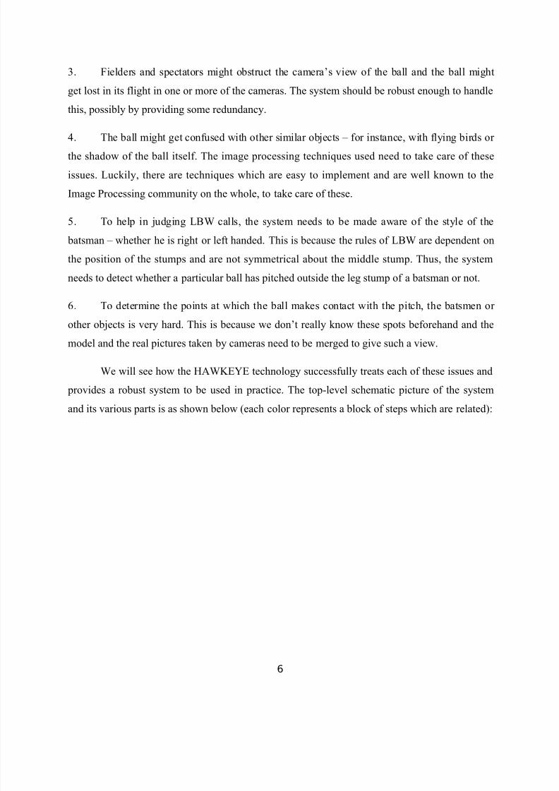
=. >ielders and spectators might obstruct the cameras view of the ball and the ball might
get lost in its flight in one or more of the cameras. The system should be robust enough to handle
this, possibly by providing some redundancy.
7. The ball might get confused with other similar objects ? for instance, with flying birds or
the shadow of the ball itself. The image processing techni9ues used need to take care of these
issues. &uckily, there are techni9ues which are easy to implement and are well known to the
Image *rocessing community on the whole, to take care of these.
B. To help in judging &'! calls, the system needs to be made aware of the style of the
batsman ? whether he is right or left handed. This is because the rules of &'! are dependent on
the position of the stumps and are not symmetrical about the middle stump. Thus, the system
needs to detect whether a particular ball has pitched outside the leg stump of a batsman or not.
;. To determine the points at which the ball makes contact with the pitch, the batsmen or
other objects is very hard. This is because we dont really know these spots beforehand and the
model and the real pictures taken by cameras need to be merged to give such a view.
!e will see how the A!"#$# technology successfully treats each of these issues and
provides a robust system to be used in practice. The top+level schematic picture of the system
and its various parts is as shown below Ceach color represents a block of steps which are related)
6

7/21/2019 Hawkeye Technology
http://slidepdf.com/reader/full/hawkeye-technology-56e0cdbb79c5c 7/29
>ig. =.2 awk+#ye flow diagram
The figure above shows precisely the steps that are involved in the computation. The
process is started with some calibration of the cameras. This is re9uired to deal with the problem
raised in 2 above, about the non+uniform distance of the cameras from the playing area. After this
basic calibration is done and the system is up and running, we can start processing the video
input which we get from the cameras. In each of the images obtained, the first aim is to find the
ball initial position. :nce this is done, a geometric algorithm is used to look at multiple images
7

7/21/2019 Hawkeye Technology
http://slidepdf.com/reader/full/hawkeye-technology-56e0cdbb79c5c 8/29
Cwhich are 0D and then combine them cleverly to get the co+ordinates of the ball in =D space.
This process is now repeated for multiple times every second Ctypically at the rate of 211 times
per second.
Thus, we have the position of the ball in =D space at many moments in every second. The
final step is to process these multiple positions and find a suitable fitting curve which best
describes the flight of the ball. As we have sampled the positions of the ball at very short time
intervals, the flight of the ball can be very accurately determined. A description of the e(act
algorithms involved in the entire process will be skipped here. !e instead try to give an intuitive
description of each step in great detail, so as to give the reader a feel of what goes into the
system, without plunging into the gory details.
. Conc&u'ion:
The general working of awk+#ye %ystem is mentioned.
8

7/21/2019 Hawkeye Technology
http://slidepdf.com/reader/full/hawkeye-technology-56e0cdbb79c5c 9/29
CHAPTER
7OR8IN9 O6 HA78#E5E
.1 Introduction:
In this chapter, the principle and working of the awk+#ye system is discussed.
>or most sports fans it is not important to know how awk+eye works, but here is a lot of
interesting science and technology behind the images that appear on the T4 screen. In cricket
matches awk+eye technology is based upon the images captured by si( cameras, three on each
side to the wicket. Through these si( cameras, all round and =D images can be captured, which
allows for the path of the ball to be tracked. The prediction side comes about through the use of
logarithms based on known laws of physics and trajectories.
awk+#ye uses ; high speed specialist vision processing cameras which are positioned
around the ground and calibrated. In addition the system uses the two EatF broadcast cameras
and calibrates them so that the graphic is always overlaid in the right place. All cameras have
Eanti wobbleF software to deal with camera movement. !hen a ball is bowled, the system is able
to automatically find the ball within each frame of video from each camera. 'y combining the
positions of the ball in each of the cameras, the =d position of the ball is measured through+out
the delivery. 'y measuring the position of the ball at multiple frames post bounce, the speed,direction of travel, swing and dip can be calculated for that specific delivery. /sing these
measured characteristics of the balls flight up to impact, the future path is predicted.
.2 Princi(&e:
All awk+#ye systems are based on the principles of triangulation using the visual
images and timing data provided by at least si( high+speed video cameras located at different
locations and angles around the area of play.
Trian$u&ation:
Triangulation is a process of determining the location of a point by measuring angles to it
from known points from the fi(ed baseline.
9

7/21/2019 Hawkeye Technology
http://slidepdf.com/reader/full/hawkeye-technology-56e0cdbb79c5c 10/29
>ig 7.2 Triangulation
. Co%(onent':
The hawk eye system consists of two significant parts)
Tracking %ystem.2. amera.0. %peed gun.
4ideo -eplay %ystem.
..1 Trac"in$ Sy'te%:
10

7/21/2019 Hawkeye Technology
http://slidepdf.com/reader/full/hawkeye-technology-56e0cdbb79c5c 11/29
The tracking data provides the coaches and players with the information for :! they
have performed. The tracking system consists of igh speed vision processing cameras to track
the ball from the bowlers hand to the batsman.
The system will automatically calculate the following information)
2. The speed of the ball leaving the bowler5s hand.0. The swing of the ball from the bowler5s hand to where the ball pitched.
=. ow much the ball bouncedG
7. ow much the ball deviated sideways off the wicketG
B. A prediction of where the ball would have passed the stumps.
1. Ca%era:
awkeye cameras placed high above the court to track the trajectory Cpath followed ofthe ball. It can point out the bounce of the ball up to the precision of =.;mm.The cameras record
the movement of ball at the rate of 211 frames per second.
>ig 7.0 awk+#ye ameras
2. S(eed 9un:
A speed gun measures the ball speed. It shoots a very short burst of infra+red laser and
receives it back. The gun, counts the nanoseconds it took for the light to travel to and from the
ball, divides it by two and gives the speed of the ball.
11

7/21/2019 Hawkeye Technology
http://slidepdf.com/reader/full/hawkeye-technology-56e0cdbb79c5c 12/29
>ig 7.= %peed 6un
..2 ,ideo Re(&ay Sy'te%:
Though the tracking data provides the coaches and players the information for how they
performed. The awk+#ye %ystem can incorporate more video replay cameras for analysis from
different angles, which can be controlled remotely. The video is captured and stored digitally on
hard disks. This uses display unit like monitor and projector screens.
>ig 7.7 4ideo -eplay %ystem
. Tec0no&o$y:
In this section, we go into the technical details of the steps involved in the A!"#$#
system. The process, as done before, can be broken down into the following steps)
12

7/21/2019 Hawkeye Technology
http://slidepdf.com/reader/full/hawkeye-technology-56e0cdbb79c5c 13/29
..1 T0e Ca%era':
Typically, for a cricket field, ; cameras are used. These cameras are placed around the
field at roughly the places as indicated in the diagram below)
>ig 7.B amera %etup
As one can see, the ; cameras in use are positioned at roughly ;1 degree from each other.
They are placed high in the stands, so that there is lesser chance of their view being blocked by
the fielders. There are two cameras, one each looking at the wickets directly in sideways fashion.
These ;cameras are calibrated according to the distance they are at from the pitch. In order to getgood accuracy, one needs to restrict the view of each camera to a smaller region. This means
each camera image would show a more prominent picture of the ball and hence the ball will be
located more accurately. owever, we also need to keep in mind that the whole field of play has
to be covered by just the ; cameras which are available. This puts some limitation on how
13

7/21/2019 Hawkeye Technology
http://slidepdf.com/reader/full/hawkeye-technology-56e0cdbb79c5c 14/29
restricted the view of a camera can be. 8evertheless, the accuracy obtained by using ; cameras is
acceptable to the standards prevalent today.
%ome further setting up is essential for the system to work correctly. The cameras need to
be fi(ed to some frame of reference, which is defined very conveniently in terms of the wickets
on the pitch, and the line joining them. This is useful when we want to use an automated program
to merge images from different cameras to form one =D image.
Also, to avoid unnecessary computation and make the system more efficient, the cameras
can be operated in active or passive mode. In the passive mode, no imaging is done and hence
the system is more or less completely inactive. The cameras can be triggered into active mode
either by detecting some motion in the vicinity of the pitch, or manually by some e(ternal trigger.
In either case, all the cameras are synchronized and go into active mode simultaneously. The
cameras are then designed to stay in the active mode for a fi(ed time before going off into
passive mode. This action of going into passive mode can be manually overridden in e(ceptional
cases. The different modes for the cameras are especially effective for a game like cricket as the
game involves significant pauses between phases of actual play.
As described in B in the list of issues, the system needs to know if the batsman is right or
left handed. The front view cameras are used to do this. This information, as previously said is
useful in making &'! decisions and formulating other statistics. >or instance, we commonly see
the analysis of a bowlers pitching areas done separately for a left and aright handed batsman.
!hile this is not a very difficult task to do manually every time the batsman on strike changes,
the system does provide some way of automating it. :nce this setting is done, the cameras are
ready to take pictures in their field of view and have them sent to a computer which processes
them.
..2 Pre(aration )e*ore 'tartin$ to (roce'':
Additional features might be loaded into the system to enable it to process the data in a
more reliable and useful manner. These might include a statistical generator, which is used to
produce statistics based on the data collected. These are the statistics which we see on television
during and after the match for analysis. %uch statistics can also be used by teams and players to
study their game and devise strategies against their opponents. Indeed, the raw data about the
14
7/21/2019 Hawkeye Technology
http://slidepdf.com/reader/full/hawkeye-technology-56e0cdbb79c5c 15/29
paths of the ball might be too much for any human to digest and such statistics turn out to be
easier to handle and understand. The statistics generator might also aid in storing data such as the
average velocity of the ball. This data is crucial as it can help the ball detection algorithm to
predict the rough location of the ball in an image given the position in the previous image. %uch
considerations are useful to reduce the computations involved in the processing of the data
collected from the video cameras. :nce such additional machinery is setup correctly, we are all
set to start collecting data and start processing it to churn out tangible statistics and
visualizations. It might be noted at this stage that there is some more information which might be
re9uired to process the data correctly. !e will point out such things at later points in the paper,
where it fits in more appropriately.
.. Co&or I%a$e Proce''in$ o):
This part of the system can be further divided into = major parts)
C2 Identifying pi(els representing the ball in each image.
C0 Applying some geometric algorithm on the set of images at each instant.
C= oming up with the =D position of the ball in space.
!e now e(plain each of these operations in detail)
;1< Identi*yin$ Pi=e&':
To identify the pi(els representing the cricket ball in every image taken by each of the
video cameras) An algorithm is used to find the pi(els corresponding to the ball in the image
obtained. The information which is used in order to achieve this is the size and shape of the ball.
It should be noted that the system does not use the colour of the ball as that is not really same
throughout the course of a game, nor is it same across all forms of cricket. A blob detection
scheme can be used to detect around object in the image. "nowing the appro(imate size of the
ball, we can eliminate other round objects, such as helmets worn by players. The shadow of the
ball also will resemble the ball in shape and size and thus presents itself as a very viable
candidate for a blob representing a group of pi(els corresponding to the ball itself. The position
of the sun at the given instant of time and also information about the position of the ball in
15
7/21/2019 Hawkeye Technology
http://slidepdf.com/reader/full/hawkeye-technology-56e0cdbb79c5c 16/29
previous images is used to make sure this confusion is avoided. Thus, by taking due care, we can
be sure that the round object which has been located is indeed the cricket ball, which is the object
of interest. After this stage, we have as output the ( and y coordinates of the ball in each image.
In some cases, it might be the case that the system is unable to determine the e(act position in
some images. At such times, E8ot >oundF is returned by that particular camera. :ne must note at
this point that ; cameras are used to take images. Actually, in the ideal case one can do the job
with just 7cameras. Thus, we have some redundancy and hence, can afford to have a bad result
from one of the cameras at some points and still produce a complete picture.
;2< 9eo%etric A&$orit0%:
The data ( and y co+ordinates from each camera Cor a E8ot >oundF in some cases, which
is ignored is obtained by the 6eometric Algorithm which is at work inside the A!"#$#
system. The image taken from each camera is just a 0Dimage and lacks depth. 8ow, knowing the
e(act positions of the cameras in space Cwith respect to the pitch and the ( and y co+ordinates of
the ball in more than one of the images taken by these cameras, one can determine accurately the
position of the ball in =D.
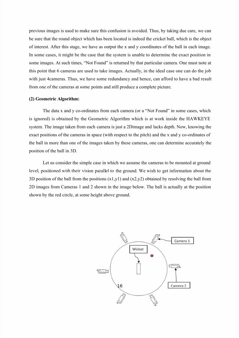
&et us consider the simple case in which we assume the cameras to be mounted at ground
level, positioned with their vision parallel to the ground. !e wish to get information about the
=D position of the ball from the positions C(2,y2 and C(0,y0 obtained by resolving the ball from
0D images from ameras 2 and 0 shown in the image below. The ball is actually at the position
shown by the red circle, at some height above ground.
16

7/21/2019 Hawkeye Technology
http://slidepdf.com/reader/full/hawkeye-technology-56e0cdbb79c5c 17/29
>ig 7.; 'all *osition
The view in the cameras will look something like the one shown below. The view below
shows the picture as seen by amera 0 in the figure above.
>ig 7.< amera 0 -esult
In this simplistic scenario, the height of the ball above the ground is given directly by the
y co+ordinate in the images, y2 and y0.'oth these values should ideally be e9ual, but we might
want to take the average in case they are not e(actly e9ual. 8ow, the one parameter we need to
determine is the depth of the ball as measured by amera 0. :nce we have that information, we
will have all the data to infer the position of the ball in =D space with respect to the pitch. 8ote
17
7/21/2019 Hawkeye Technology
http://slidepdf.com/reader/full/hawkeye-technology-56e0cdbb79c5c 18/29
that we know the positions of the cameras with respect to the pitch in advance. &et us assume
that the radial angle, as seen from the wickets marked in the figure, between amera 2 and
amera 0 is H and the radius of the field is. Then, the depth of the ball as seen from amera 0 is
as follows)
De(t0 > r#;r co' ;?< @=1'in;?<<
Thus, we see that knowing the co+ordinates of the ball in two cameras, we can get the
position of the ball in =Dspace with respect to one of the cameras and thus, with respect to the
wickets. In the realistic case, the cameras are mounted high above the ground and thus, finding
the height of the ball above the ground is not as trivial as it was here. :ne needs to rotate the a(is
correctly in order to do the calculations that were simple here as it concerned only planar
geometry. In real life, cricket grounds are not perfectly circular and hence even that has to be
taken into consideration. !e do not go into those details here, but just note that it is standard
mathematics to get the =D co+ordinates of the ball given the information in two images.
;< D (o'ition o* t0e )a&& in '(ace:
The 6eometric Algorithm described with the help of an e(ample above provides us with a
ready recipe to find the =D position of the ball in space. !e just use this method and as a result,
now have the position of the ball as captured at that instant, in =D space, with respect to any of
the reference points we had considered while setting up the system.
.. Puttin$ 6ra%e' at ,ariou' Ti%e' To$et0er:
8ow we have the e(act position of the ball in =D space at a given instant of time. 8e(t,
what needs to be done is putting together this data, collected at various time instants into a single
picture which shows us the trajectory of the ball. !e can split this part of the process into two
parts. Again, the reader should understand that these parts are very much related and we split
them here in our e(planation just to make it easily understandable. The two parts to this
computation are)
C2 Tracking the ball at various instants.
18

7/21/2019 Hawkeye Technology
http://slidepdf.com/reader/full/hawkeye-technology-56e0cdbb79c5c 19/29
C0 *redicting the flight or trajectory of the ball.
;1< Trac"in$ t0e )a&& at variou' in'tant':
%uppose the images are taken by cameras at timest1, t2.....tn, during the play of a single
ball. Doing the computation as described above at each time instant ti, 1JiJn, we will get n
points, say C(i,yi,zi for 1JiJ1 8ow, on the model that we have built previously consisting of a
picture of the pitch, ground and wickets etc., we plot these n points. !hen looked at in their
proper se9uence, these points tell us about the path followed by the ball when it travelled during
the last ball that was played. !ith these points plotted in the =Dspace, we can move on to the
ne(t and final stage in the processing of a single delivery, namely, predicting the flight of the
ball.
;2< Predictin$ t0e *&i$0t or traBectory o* t0e )a&&:
!e have n points in space which we know represent the position of the ball at some
particular time instants, which are also known. 8ow, there is a standard techni9ue, used
commonly in the field of omputer Aided 6eometric Design which can be invoked here. This
allows us to draw as good an appro(imation as re9uired to the original curve, passing through the
given points0. This techni9ue gives us a curve which is continuous and differentiable, meaning it
is smooth all along, starting at the first point and ending at the last point among our n points.
This smooth curve is an appro(imation to the original curve which the ball would have followed.
The more points we can get on the curve and the higher degree of polynomial basis we choose to
use, we will end up with better appro(imations to the original curve. The better appro(imations
obviously come at some additional cost ? the added cost of computation of the appro(imation.
ence, the system uses some degree such that the computation time is small enough, at the same
time the accuracy is acceptable. ore can be done with the information about the points. !e can
also e(tend the curve to points which we have not been recorded at all ? indeed, it might be the
case that the ball struck the batsman and deflected away, but we want to see where the ball was
headed, particularly to help adjudge &'! cases. This e(tension uses some basic mathematics
and ensures that the e(tended curve is also smooth at all points, particularly at the point from
where the e(tended part starts that is the last point which we have recorded among the points.
During the flight of the ball, it might go through some points which are of special interest. These
19

7/21/2019 Hawkeye Technology
http://slidepdf.com/reader/full/hawkeye-technology-56e0cdbb79c5c 20/29
include the ball hitting the pitch, the stumps, and the batsman among others. These points are
predicted by superimposing the trajectory which we built, onto the model that we have fed into
the system. It should be noted that there is a possibility that such critical points may not be
recorded in any of the images taken by the system and in such casesK the reliance is completely
on the predicted flight of the ball. Also, for the particular key+event of the ball striking the
batsman, the sideways cameras, which look directly at the wickets at either end of the pitch, are
the most reliable sources.
.3 Conc&u'ion:
In this chapter, we have seen the principle, components, technical details and working of
an A!"+#$# system in complete detail.
20

7/21/2019 Hawkeye Technology
http://slidepdf.com/reader/full/hawkeye-technology-56e0cdbb79c5c 21/29
CHAPTER 3
APPLICATIONS O6 HA78#E5E S5STE
3.1 Introduction:
A!"#$# has had far+reaching conse9uences in many sports. *rimarily in cricket,
A!"#$# is a process that makes the current judgmental call on a &'! decision, very
predictive. !hile no technology is flawless and A!" #$# has its own share of these, it is up
to LL.LM accurate. This has made the &'! decision, a predictive one. ore importantly, such
technology can be used to evaluate the skills of the umpire as well. The #ngland ricket 'oard
C#' has already set+up the A!"#$# system not only at about 21cricket venues around the
country but also in the training academy to aid umpires, as well.
9at0erin$ 'tati'tic':
!hile the awk+#ye has made its mark and derives its appeal from the ability to predict
the flight of the delivery, it is a very useful tool for collecting statistics. The information
associated with each delivery bowled is routinely processed, even when the outcome of the
delivery is not doubted. As a result, the strategy used by a bowler as a function of bowling spells,
delivery no. in the over, batsman facing the delivery and so on can be gauged. %imilarly, the
scoring patterns of a batsman around the ground using wagon+wheels are routine in match day
telecasts. These are so cleverly generated that they give a real+life feel to it. ommentators also
are able to move them about to make a finer point, about a batsman. owever, appealing and
nice that it may seem, a keen cricketing eye will notice that the wagon wheel is less accurate than
the other data. This is because the wagon+wheel is generated from data collected from outside the
pre+determined pitch area. The location, depth, trajectory of the ball in+flight at an arbitrary point
on the ground is more difficult to determine, than when it is on the pitch. As a result, some errors
manifest. These difficulties arent faced in tennis ? where A!"#$# is used to decide whether
the ball, was within the court limits or not. In the case of Tennis, lines calls made by A!"#$#
are completely accurate. Tennis has been 9uick to adapt to this technology and A!"#$#
arbitrations are legal since the 8A%DAN+211 tennis tournament. *layers can challenge line calls,
following which A!"#$# determines whether the ball was pitched in or outO The recently
21

7/21/2019 Hawkeye Technology
http://slidepdf.com/reader/full/hawkeye-technology-56e0cdbb79c5c 22/29
concluded /% :pen N> match between >errer and 8albandian had a match+point being decided
after a line+call challenge.
!e now briefly look at the various applications of A!"#$# which the cricket
broadcasters regularly use these days.
3.1 L7 deci'ion':
As mentioned previously, the A!"#$# can accurately capture the trajectory of the ball
and also predict the future direction of the ball using mathematical calculations. This is put to use
in deciding whether a batsman was :/T &'! on a particular ball. Thus, the system determines
the e(act point at which the ball struck the batsman. /sing the trajectory of the ball up to that
point, the system predicts the path the ball would have taken had the batsman not been present in
the way. Thus one can know the lateral position of the ball with respect to the stumps as well as
the height of the ball at the point when it reaches the line of the stumps. The figure below gives
an e(ample of the trajectory of the ball being predicted. 8ote that in this picture, the system has
got rid of the batsman from the picture so as to give us a complete view of the path of the ball
since it left the bowlers hand. This is e(actly what one needs to decide if the ball would have hit
the stumps and if that is the case, the batsman has a chance of being given :/T &'!.
>ig B.2 &'! Trajectory
22

7/21/2019 Hawkeye Technology
http://slidepdf.com/reader/full/hawkeye-technology-56e0cdbb79c5c 23/29
The system is well e9uipped to handle the various comple( clauses which the &'! rule
has. >or instance, it can check if the ball had pitched outside the leg stump of the batsman. If this
is the case, the batsman is 8:T :/T even if the ball is going on to the stumps. -ecall that the
front view cameras are used to determine whether a batsman is right or left handed. That
information is useful here. Another clause states that the batsman should not be given :/T if he
is hit outside the line of off+stump and is attempting to play a shot. 8ow, the part of whether the
batsman is playing a shot has to be decided manually and the system is not capable of doing it.
owever, the point of impact is accurately known and one can see e(actly where the batsman
was hit.
The kind of accuracy which A!"#$# offers is difficult to get for any human umpire.
The system also includes a way to do probabilistic analysis and hence bring in the factor of
Ebenefit of doubtF which goes to batsman currently. The main idea behind this is to have a region
which the human umpire would believe the ball would have been in this region is just taken to be
a circle centered at the accurate position of the ball and radius .The value of this radius is
calculated taking into consideration the distance between the point of impact of the ball with the
batsman and the stumps ? that is, the distance which the ball is yet to cover. This models 9uite
accurately the uncertainty which the umpires feel while making the decision manually. Thus, if
the batsman is playing forward, the radius will have a higher value, than when the batsman is
struck, playing back. To keep the Ebenefit of doubtF still with the batsman, the decision goes in
favour of the bowler only if a significant portion of the probable region Ccircle or radius
described above lies in line with the stumps. The system thus is very robust and seems to be
better than human umpires as it stands ? and it can only improve.
3.2 7a$on 70ee&':
The trajectories which the ball has taken after being hit by the batsman are recorded in
the system. This is used to generate a graphic showing 2s, 0s, =s, 7s, and ;s all indifferent
colours for a batsman. These details allow the commentators, spectators and players to analyze
the scoring areas of the batsman and also judge if he has played more shots along the turf or in
the air. %uch information is vital for a fielding captain, who might alter his field placement in
subse9uent matches to adapt to the hitting pattern of a particular batsman.
23

7/21/2019 Hawkeye Technology
http://slidepdf.com/reader/full/hawkeye-technology-56e0cdbb79c5c 24/29
>ig B.0 !agon !heel
3. Pitc0 a(':
As shown below, the *itch ap graphic uses information about the position where the
ball bounced on the pitch. The image above clearly shows the pitch being divided into various
EzonesF which the e(perts consider in their analysis. It can be very easily seen where the bowler
has been pitching the ball primarily. 'ased on such pitch maps, one can easily see general
characteristics of bowlers+for instance, on a particular day a bowler might be taken for a lot of
runs. A!"#$# can show the areas in which the bowler landed the balls and he might be able
to find out he was too short on most occasions and hence was being taken for runs. 'atsmen also
use such graphics to study the general tendency of the bowler and can plan to play him in
subse9uent games.
>ig B.= *itch aps
24

7/21/2019 Hawkeye Technology
http://slidepdf.com/reader/full/hawkeye-technology-56e0cdbb79c5c 25/29
3. De#S(in:
The De+%pin graphics help us in understanding how the ball has deviated after pitching.
The graphic produced shows the predicted path of the ball, had it held its line even after pitching.
This is particularly interesting to look at, in the case of spinners, where one can see both theflight being given by the bowler and the spin that he manages to e(tract from the pitch. &ooking
at the action and the De+%pin graphics for a particular bowler is useful for batsman to notice any
changes in action when the spinner is bowling a EtrickF ball ?which might be a googly or flipper
in the case of a leg spinner, or a EdoosraF in the case of an off spinner.
>ig B.7 De+%pin
3.3 Rai& Ca%:
The P-ail am Cside view shot of the 4- !orld can be used to represent
differences in speed, bounce and delivery. The trajectories are animated whilst the speeds
provide further evidence of a bowlers variation or a telling comparison between athletes.
25

7/21/2019 Hawkeye Technology
http://slidepdf.com/reader/full/hawkeye-technology-56e0cdbb79c5c 26/29
>ig B.B -ail am
3.4 ee0ive':
'eehives show where the ball has passed the batsman. As with the *itch ap the colored
balls correspond to the number of runs that the batsman has achieved from that delivery. awk+#ye 'eehives can now be shown against a photo realistic or virtual realistic world, as with the
!agon !heel feature.
>ig B.< 'eehives
3. Tenni':
The awk+#ye :fficiating %ystem is the first and only ball+tracking system tohave
passed stringent IT> testing measures. It is accurate, reliable and practical.
8ot only is the awk+#ye :fficiating %ystem vital for ensuring that high pressure points
do not fall prey to umpiring mistakes, it brings the fans closer to the action. %pectators watch
alongside their heroes and heroines on court as awk+#ye shows whether a ball wasPin or out
on stadia big.
26

7/21/2019 Hawkeye Technology
http://slidepdf.com/reader/full/hawkeye-technology-56e0cdbb79c5c 27/29
>ig B.< Tennis -eview %ystem
3./ Conc&u'ion:
In this chapter, the vast applications of the awk+#ye system are discussed.
27

7/21/2019 Hawkeye Technology
http://slidepdf.com/reader/full/hawkeye-technology-56e0cdbb79c5c 28/29
CHAPTER 4
CONCLUSION
!e have looked at various aspects of the A!"#$# technology. Initially, we outlined
the main problems which one could encounter while trying to implement such a system for a
sport like cricket. Then, we looked into the details of each step of the process which finally gives
us the wonderful looking graphics that we see on T4 during cricket analysis shows. !e got a fair
understanding of the algorithms and mathematics which goes into the system. !ith the help of
e(amples, we looked at the applications which the technology finds in modern day sport, with
cricket being our main focus. !e got an understanding of how the graphics can be produced,
using the setup, which also was described in detail.
!e have thus seen that the A!"#$# is a great innovation, which puts technology to
good use in the field of sports. The technology is used widely these days, in sports such as Tennis
and ricket. The accuracy which can be achieved with the use of the system is making the
authorities think seriously about reducing the human error component involved in important
decisions. As the system runs in real time, there is no e(tra time re9uired to see the visualizations
and graphics. The system is also a great tool which can be used by players, statisticians,
tacticians, coaches to analyze previous games and come up with strategies for subse9uent ones.
28

7/21/2019 Hawkeye Technology
http://slidepdf.com/reader/full/hawkeye-technology-56e0cdbb79c5c 29/29
RE6ERENCES
2. http)QQv=.espacenet.comQte(tdoc
0. http)QQwww.usopen.orgQenR/%QnewsQarticlesQ011;+1S+21Q=. http)QQwww.nzherald.co.nzQsectionQ7Qstory.cfmGcRidJ7
7. http)QQarchive.gulfnews.comQindepthQdubaitennis011<Q1S=<L
B. http)QQwww.wikipedia.orgQwikiQhawkeye
6. http)QQwww.hawkeyetechnology.comQtechQ