Embed Size (px)
Citation preview

for DIN rail according to EN 60715
Application
Surge arresters are used to weaken residual currents from upstream lightningprotection steps and to limit system-induced or system-generated overvoltagesurges.
HAW562 units are primarily used in process automation and in measuring andcommunication technology within the chemicals, pharmaceuticals, water andwastewater sectors as well as in the food industry.
Your benefits
• Increased plant availability as surge arrester is perfectly matched to the electroniccomponents involved in process automation and process measuring technology.
• Application in Ex areas - optionally available with intrinsically safe approvals.• SIL2 (optional)• Direct and indirect shield grounding• Investment intensive measuring instruments protected.• Vibration and shock tested according to EN 60068-2
Products Solutions Services
Technical InformationHAW562Surge arresters
TI01012K/09/EN/15.1471254536
HAW562
2
Function and system design
Operating principle The HAW562 surge arrester is used to protect electronic components from being destroyed byovervoltage. It ensures that overvoltage surges which occur in signal cables (e.g. 4 to 20 mA), incommunication lines (Field buses) and in power lines are safely passed into the ground.
The functionality of the transmitter or the electronics component to be protected is not affected.
Operation of power supply protection units:
Using the impedance-free connection of the protection unit, interference voltage drops cannot beintroduced on the power lines.
Operation of signal cable protection units:
Low and matched disconnection impedance between the individual protection steps within the unitguarantee high compatibility with the system to be protected.
Available versions For power lines:• HAW562-AAB to protect power lines in non-Ex areas, voltage range 10-55 V• HAW562-AAC to protect power lines in non-Ex areas, voltage range 90-230 VFor signal cables and communication lines:• HAW562-AAA to protect signal cables in non-Ex areas• HAW562-8DA with Ex ia approval to protect signal cables• HAW562-AAD to protect communication lines (RS485, Modbus, Profibus DP) in non-Ex areas• HAW562-AAE protection module for Prosonic FMU90 in non-Ex areas
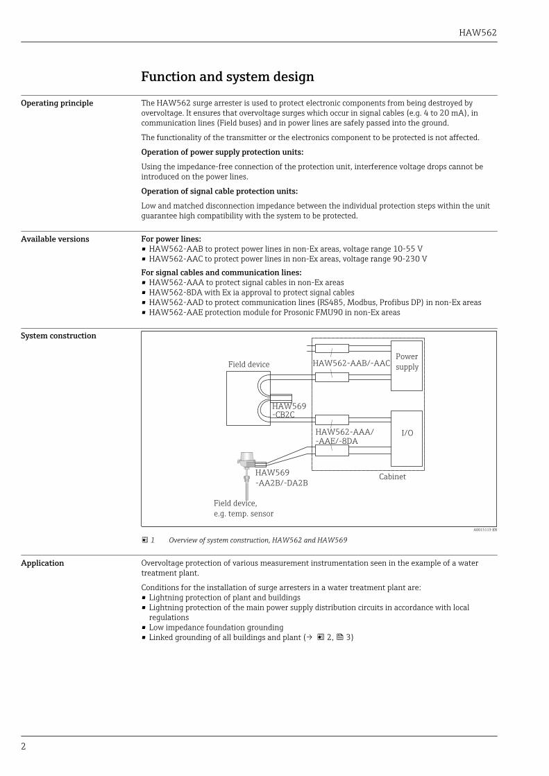
System construction
HAW562-AAB/-AAC
HAW569-CB2C
HAW562-AAA/-AAE/-8DA
HAW569
-AA2B/-DA2B
Field device,
e.g. temp. sensor
Power
supply
I/O
Field device
Cabinet
A0015113-EN
1 Overview of system construction, HAW562 and HAW569
Application Overvoltage protection of various measurement instrumentation seen in the example of a watertreatment plant.
Conditions for the installation of surge arresters in a water treatment plant are:• Lightning protection of plant and buildings• Lightning protection of the main power supply distribution circuits in accordance with local
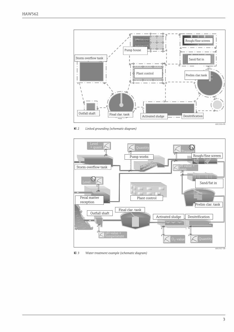
regulations• Low impedance foundation grounding• Linked grounding of all buildings and plant (→ 2, 3)
HAW562
3
Plant control
Storm overflow tank
Pump house
Rough/fine screen
Sand/fat in
Prelim clar.tank
DenitrificationActivated sludgeOutfall shaft Final clar. tank
A0015026-EN
2 Linked grounding (schematic diagram)
Quantity
Storm overflow tank
Pump works
Fecal matter
receptionPlant control
Sand/fat in
Final clar. tankOutfall shaft
Activated sludge
Prelim clar. tank
Denitrification
Level+ quant.
Pressure
Level
pH value +temperature
pH value +temp.
O2-value Quantity
Rough/fine screen
A0015027-EN
3 Water treatment example (schematic diagram)
HAW562
4
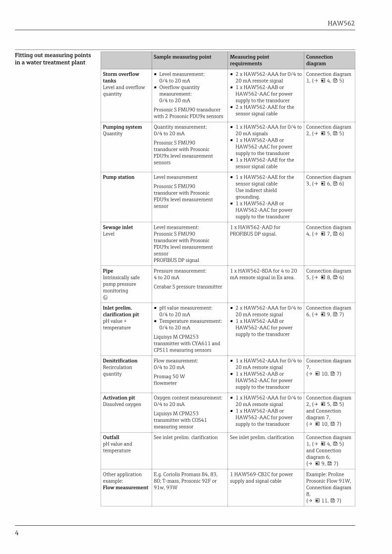
Fitting out measuring pointsin a water treatment plant
Sample measuring point Measuring pointrequirements
Connectiondiagram
Storm overflowtanksLevel and overflowquantity
• Level measurement:0/4 to 20 mA
• Overflow quantitymeasurement:0/4 to 20 mA
Prosonic S FMU90 transducerwith 2 Prosonic FDU9x sensors
• 2 x HAW562-AAA for 0/4 to20 mA remote signal
• 1 x HAW562-AAB orHAW562-AAC for powersupply to the transducer
• 2 x HAW562-AAE for thesensor signal cable
Connection diagram1, (→ 4, 5)
Pumping systemQuantity
Quantity measurement:0/4 to 20 mA
Prosonic S FMU90transducer with ProsonicFDU9x level measurementsensors
• 1 x HAW562-AAA for 0/4 to20 mA signals
• 1 x HAW562-AAB orHAW562-AAC for powersupply to the transducer
• 1 x HAW562-AAE for thesensor signal cable
Connection diagram2, (→ 5, 5)
Pump station Level measurement
Prosonic S FMU90transducer with ProsonicFDU9x level measurementsensor
• 1 x HAW562-AAE for thesensor signal cableUse indirect shieldgrounding.
• 1 x HAW562-AAB orHAW562-AAC for powersupply to the transducer
Connection diagram3, (→ 6, 6)
Sewage inletLevel
Level measurement:Prosonic S FMU90transducer with ProsonicFDU9x level measurementsensorPROFIBUS DP signal
1 x HAW562-AAD forPROFIBUS DP signal.
Connection diagram4, (→ 7, 6)
PipeIntrinsically safepump pressuremonitoring0
Pressure measurement:4 to 20 mA
Cerabar S pressure transmitter
1 x HAW562-8DA for 4 to 20mA remote signal in Ex area.
Connection diagram5, (→ 8, 6)
Inlet prelim.clarification pitpH value +temperature
• pH value measurement:0/4 to 20 mA
• Temperature measurement:0/4 to 20 mA
Liquisys M CPM253transmitter with CYA611 andCPS11 measuring sensors
• 2 x HAW562-AAA for 0/4 to20 mA remote signal
• 1 x HAW562-AAB orHAW562-AAC for powersupply to the transducer
Connection diagram6, (→ 9, 7)
DenitrificationRecirculationquantity
Flow measurement:0/4 to 20 mA
Promag 50 Wflowmeter
• 1 x HAW562-AAA for 0/4 to20 mA remote signal
• 1 x HAW562-AAB orHAW562-AAC for powersupply to the transducer
Connection diagram7,(→ 10, 7)
Activation pitDissolved oxygen
Oxygen content measurement:0/4 to 20 mA
Liquisys M CPM253transmitter with COS41measuring sensor
• 1 x HAW562-AAA for 0/4 to20 mA remote signal
• 1 x HAW562-AAB orHAW562-AAC for powersupply to the transducer
Connection diagram2, (→ 5, 5)and Connectiondiagram 7,(→ 10, 7)
OutfallpH value andtemperature
See inlet prelim. clarification See inlet prelim. clarification Connection diagram1, (→ 4, 5)and Connectiondiagram 6,(→ 9, 7)
Other applicationexample:Flow measurement
E.g. Coriolis Promass 84, 83,80; T-mass, Prosonic 92F or91w, 93W
1 HAW569-CB2C for powersupply and signal cable
Example: ProlineProsonic Flow 91W,Connection diagram8,(→ 11, 7)
HAW562
5
12 14 9 11
1
2
42
41
4
513 10
Prosonic S
FMU90
L / +
N / -
FDUFDU
1'2'
3'4'
24 V : HAW562-AAB
230 V : HAW562-AAC
1'2'
3'4'
1 2
3 4
1 2
3 4
12
34
1'2'
3'4'
12
34
1'2'
3'4'
1 2
3 466 B(P)
65 A(N)
2x Sensor signal,
2x HAW562-AAE:
2x Measurement signal,
2x HAW562-AAA
red
black
yellow
1 - Signal ground
2, 4 - Signal lines
3 - n.c.
Cable shield
Power supply
A0015028-EN
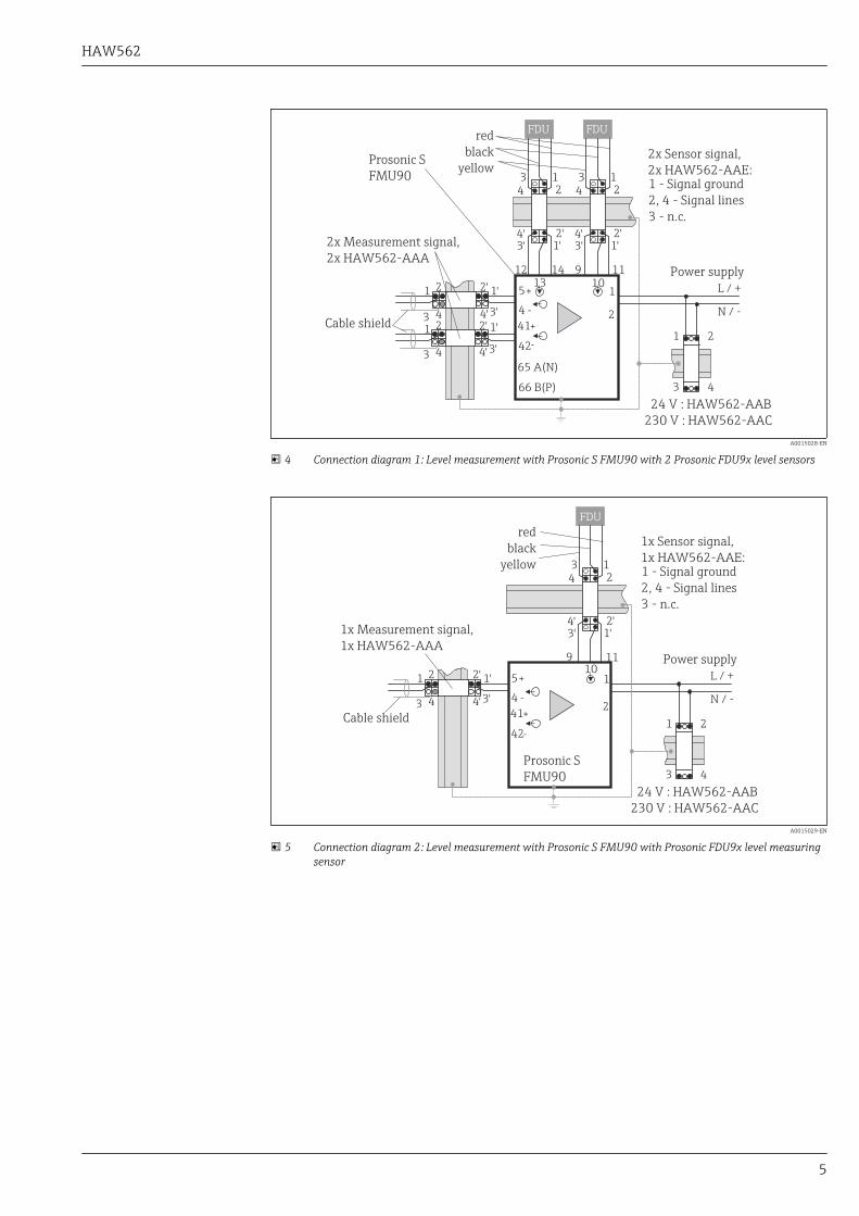
4 Connection diagram 1: Level measurement with Prosonic S FMU90 with 2 Prosonic FDU9x level sensors
1
2
42
41
4
5 L / +
N / -
1'2'
3'4'
24 V : HAW562-AAB
230 V : HAW562-AAC
1 2
3 4
1 2
3 4
9 1110
FDU
12
34
1'2'
3'4'
Prosonic S
FMU90
red
black
yellow
1x Measurement signal,
1x HAW562-AAA
Cable shield
Power supply
1x Sensor signal,
1x HAW562-AAE:1 - Signal ground
2, 4 - Signal lines
3 - n.c.
A0015029-EN
5 Connection diagram 2: Level measurement with Prosonic S FMU90 with Prosonic FDU9x level measuringsensor
HAW562
6
1
2
42
41
4
5 L / +
N / -
24 V : HAW562-AAB
230 V : HAW562-AAC
1 2
3 4
9 1110
FDU
12
34
1'2'
3'4'
Prosonic S
FMU90
red
black
yellow
Power supply
1x Sensor signal,
1x HAW562-AAE:1 - Signal ground
2, 4 - Signal lines
3 - n.c.
A0015037-EN
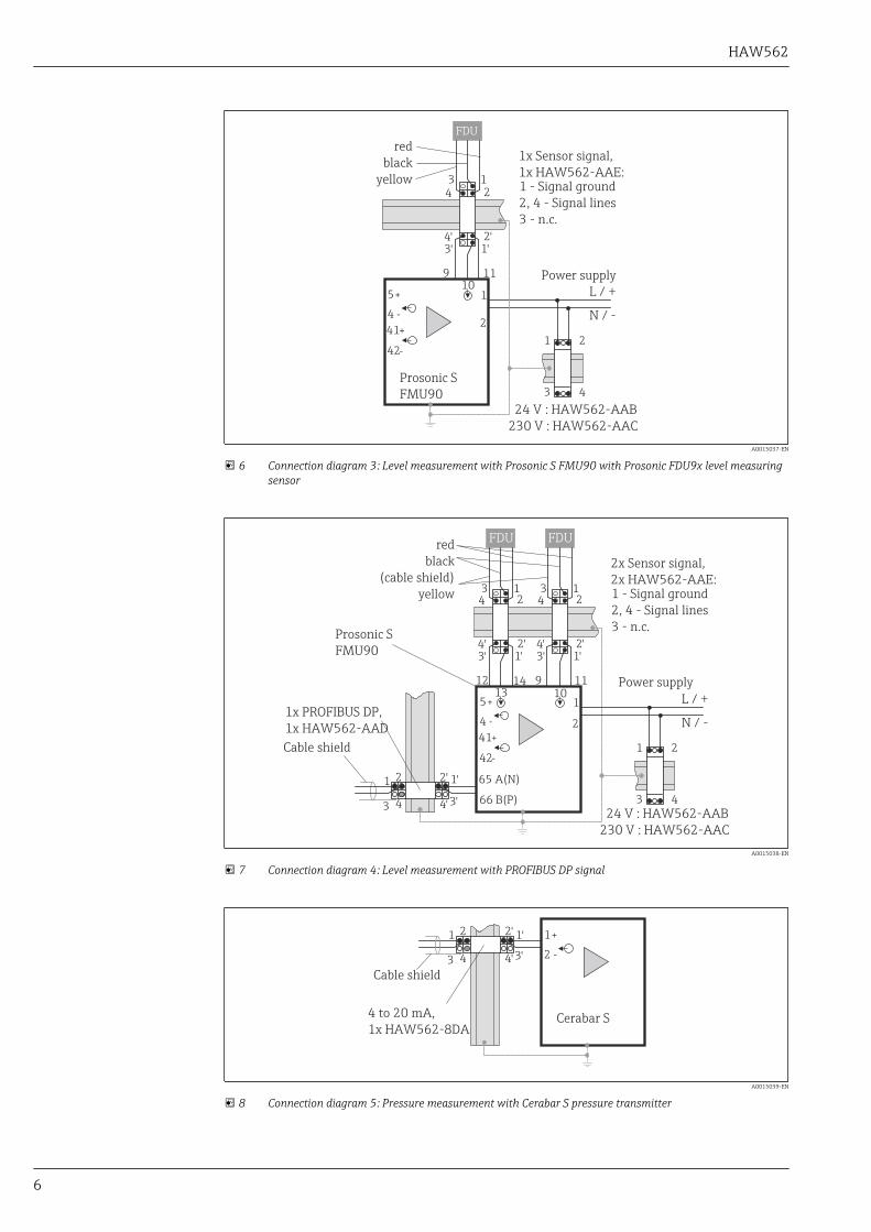
6 Connection diagram 3: Level measurement with Prosonic S FMU90 with Prosonic FDU9x level measuringsensor
12 14 9 11
1
2
42
41
4
513 10
Prosonic S
FMU90
L / +
N / -
FDUFDU
24 V : HAW562-AAB
230 V : HAW562-AAC
12
34
1'2'
3'4'
12
34
1'2'
3'4'
1 2
3 466 B(P)
65 A(N)1'2'
3'4'
1 2
3 4
1x PROFIBUS DP,
1x HAW562-AAD
2x Sensor signal,
2x HAW562-AAE:1 - Signal ground
2, 4 - Signal lines
3 - n.c.
red
black
(
yellow
cable shield)
Cable shield
Power supply
A0015038-EN
7 Connection diagram 4: Level measurement with PROFIBUS DP signal
2
11'2'
3'4'
1 2
3 4
Cerabar S4 to 20 mA,
1x HAW562-8DA
Cable shield
A0015039-EN
8 Connection diagram 5: Pressure measurement with Cerabar S pressure transmitter
HAW562
7
1
2
34
33
32
31 L / +
N / -
1'2'
3'4'
24 V : HAW562-AAB
230 V : HAW562-AAC
1'2'
3'4'
1 2
34
12
3 4
1 2
3 4
Liquisys M
CPM 253
2x Measurement signal,
2x HAW562-AAA
Cable
shield
Power supply
A0015040-EN
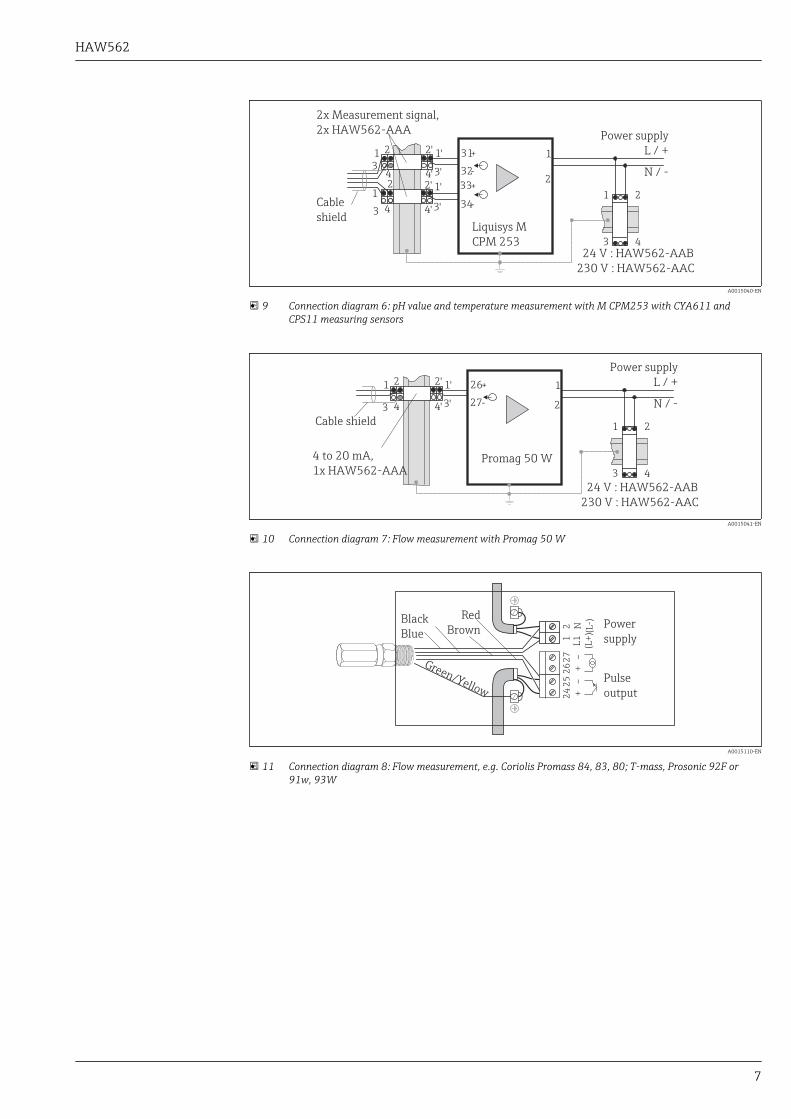
9 Connection diagram 6: pH value and temperature measurement with M CPM253 with CYA611 andCPS11 measuring sensors
1
227
26 L / +
N / -
24 V : HAW562-AAB
230 V : HAW562-AAC
1 2
3 4
Promag 50 W
1'2'
3'4'
1 2
3 4
Power supply
4 to 20 mA,
1x HAW562-AAA
Cable shield
A0015041-EN
10 Connection diagram 7: Flow measurement with Promag 50 W
21
27 –
25 –
26 +
24 +
L1
(L+
)N (L-) Power
supply
Pulse
output
Black
Blue
Red
Brown
Green/Yellow
A0015110-EN
11 Connection diagram 8: Flow measurement, e.g. Coriolis Promass 84, 83, 80; T-mass, Prosonic 92F or91w, 93W
HAW562
8
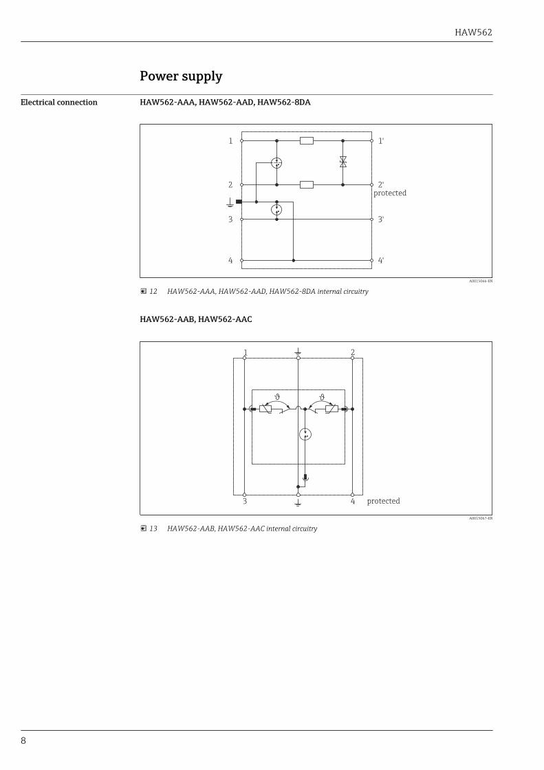
Power supply
Electrical connection HAW562-AAA, HAW562-AAD, HAW562-8DA
1
2
3
4
1'
2'
3'
4'
protected
A0015066-EN
12 HAW562-AAA, HAW562-AAD, HAW562-8DA internal circuitry
HAW562-AAB, HAW562-AAC
1 2
3 4 protected
A0015067-EN
13 HAW562-AAB, HAW562-AAC internal circuitry
HAW562
9
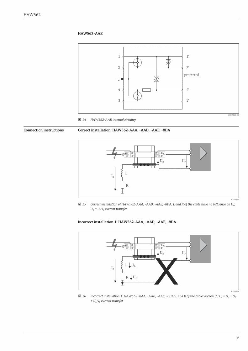
HAW562-AAE
1
2
4
3
1'
2'
4'
3'
protected
A0015068-EN
14 HAW562-AAE internal circuitry
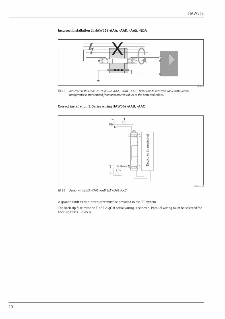
Connection instructions Correct installation: HAW562-AAA, -AAD, -AAE, -8DA
L
R
Ia
Up Ur
A0015072
15 Correct installation of HAW562-AAA, -AAD, -AAE, -8DA; L and R of the cable have no influence on Ur;Up = Ur; Ia current transfer
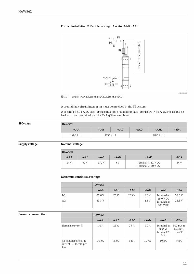
Incorrect installation 1: HAW562-AAA, -AAD, -AAE, -8DA
L
R
Ia
Up Ur
UL
UR
A0015073
16 Incorrect installation 1: HAW562-AAA, -AAD, -AAE, -8DA; L and R of the cable worsen Ur; Ur = Up + UR
+ UL; Ia current transfer
HAW562
10
Incorrect installation 2: HAW562-AAA, -AAD, -AAE, -8DA
A0015074
17 Incorrect installation 2: HAW562-AAA, -AAD, -AAE, -8DA; Due to incorrect cable installation,interference is transmitted from unprotected cables to the protected cables.
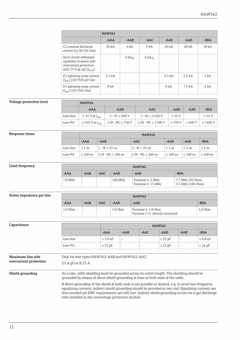
Correct installation 1: Series wiring HAW562-AAB, -AAC
1 2
3 4
*)L
NPE/
Dev
ice
to b
e p
rote
cted
*) TT system
RCD
A0015081-EN
18 Series wiring HAW562-AAB, HAW562-AAC
A ground fault circuit interrupter must be provided in the TT system.
The back-up fuse must be F ≤25 A gG if serial wiring is selected. Parallel wiring must be selected forback-up fuses F > 25 A.
HAW562
11
Correct installation 2: Parallel wiring HAW562-AAB, -AAC
1 2
3 4
*) L
NPE/
*) TT system
RCD
Dev
ice
to b
e p
rote
cted
A0015082-EN
19 Parallel wiring HAW562-AAB, HAW562-AAC
A ground fault circuit interrupter must be provided in the TT system.
A second F2 ≤25 A gG back-up fuse must be provided for back-up fuse F1 > 25 A gG. No second F2back-up fuse is required for F1 ≤25 A gG back-up fuses.
SPD class HAW562
-AAA -AAB -AAC -AAD -AAE -8DA
Type 1 P1 Type 3 P3 Type 1 P1
Supply voltage Nominal voltage
HAW562
-AAA -AAB -AAC -AAD -AAE -8DA
24 V 60 V 230 V 5 V Terminal 4: 12 V DCTerminal 2: 80 V DC
24 V
Maximum continuous voltage
HAW562
-AAA -AAB -AAC -AAD -AAE -8DA
DC: 33.0 V 75 V 255 V 6.0 V Terminal 4:15.0 V DC
Terminal 2:180 V DC
33.0 V
AC: 23.3 V 4.2 V 23.3 V
Current consumption HAW562
-AAA -AAB -AAC -AAD -AAE -8DA
Nominal current [IL] 1.0 A 25 A 25 A 1.0 A Terminal 4:0.45 A
Terminal 2:3 A
500 mA atTamb80 °C(176 °F)
C2 nominal dischargecurrent [In] (8/20) perline
10 kA 2 kA 3 kA 10 kA 10 kA 5 kA
HAW562
12
HAW562
-AAA -AAB -AAC -AAD -AAE -8DA
C2 nominal dischargecurrent [In] (8/20) total
20 kA 4 kA 5 kA 20 kA 20 kA 10 kA
Short circuit withstandcapability at mains-sideovercurrent protectionwith 25 A gL/gG (ISCCR)
6 kAeff 6 kAeff
D1 lightning surge current[Iimp] (10/350) per line
2.5 kA 2.5 kA 2.5 kA 1 kA
D1 lightning surge current[Iimp] (10/350) total
9 kA 9 kA 7.5 kA 2 kA
Voltage protection level HAW562
-AAA -AAB -AAC -AAD -AAE -8DA
Line/line ≤ 52 V at Iimp L - N: ≤ 400 V L - N: ≤ 1 250 V ≤ 25 V ≤ 52 V
Line/PG ≤ 550 V at Iimp L/N - PE: ≤ 730 V L/N - PE: ≤ 1 500 V ≤ 550 V ≤ 600 V ≤ 1 400 V
Response times HAW562
-AAA -AAB -AAC -AAD -AAE -8DA
Line/line ≤ 1 ns L - N: ≤ 25 ns L - N: ≤ 25 ns ≤ 1 ns ≤ 1 ns ≤ 1 ns
Line/PG ≤ 100 ns L/N - PE: ≤ 100 ns L/N - PE: ≤ 100 ns ≤ 100 ns ≤ 100 ns ≤ 100 ns
Limit frequency HAW562
-AAA -AAB -AAC -AAD -AAE -8DA
7.8 MHz 100 MHz Terminal 4: 2 MHzTerminal 2: 15 MHz
7.7 MHz (50 Ohm)3.2 MHz (100 Ohm)
Series impedance per line HAW562
-AAA -AAB -AAC -AAD -AAE -8DA
1.0 Ohm - - 1.0 Ohm Terminal 4: 1.8 OhmTerminal 1+2: directly connected
1.0 Ohm
Capacitance HAW562
-AAA -AAB -AAC -AAD -AAE -8DA
Line/line ≤ 1.0 nF - - ≤ 25 pF - ≤ 0.8 nF
Line/PG ≤ 25 pF - - ≤ 25 pF - ≤ 16 pF
Maximum line sideovercurrent protection
Only for unit types HAW562-AAB and HAW562-AAC:
25 A gG or B 25 A
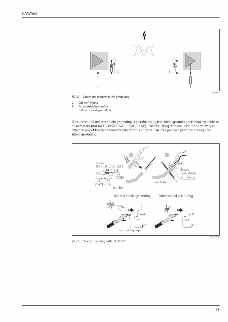
Shield grounding As a rule, cable shielding must be grounded across its entire length. The shielding should begrounded by means of direct shield grounding at least at both ends of the cable.
If direct grounding of the shield at both ends is not possible or desired, e.g. to avoid low-frequencyequalizing currents, indirect shield grounding should be provided at one end. Equalizing currents arethus avoided yet EMC requirements are still met. Indirect shield grounding occurs via a gas dischargetube installed in the overvoltage protection module.
HAW562
13
1
2 3
A0015047
20 Direct and indirect shield grounding
1 Cable shielding2 Direct shield grounding3 Indirect shield grounding
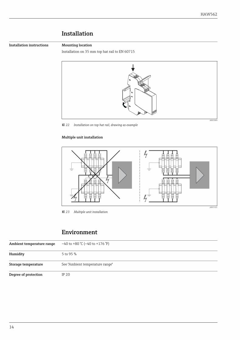
Both direct and indirect shield grounding is possible using the shield grounding terminal available asan accessory (not for HAW562-AAB, -AAC, -AAE). The insulating strip included in the delivery isfitted on one of the two connector pins for this purpose. The free pin then provides the requiredshield grounding.
2.1.
3 - 10 (0.12 - 0.39)
7
(0.28)26
(1.02)
40 (1.57)
7
Ø
12
(0.47)
4/4'
3/3'
4/4'
3/3'
mm (in)
Secure
cable shield
with clamp
Screen
Cable tie
Insulating cap
Indirect shield grounding Direct shield grounding
A0015045-EN
21 Shield grounding with HAW562
HAW562
14
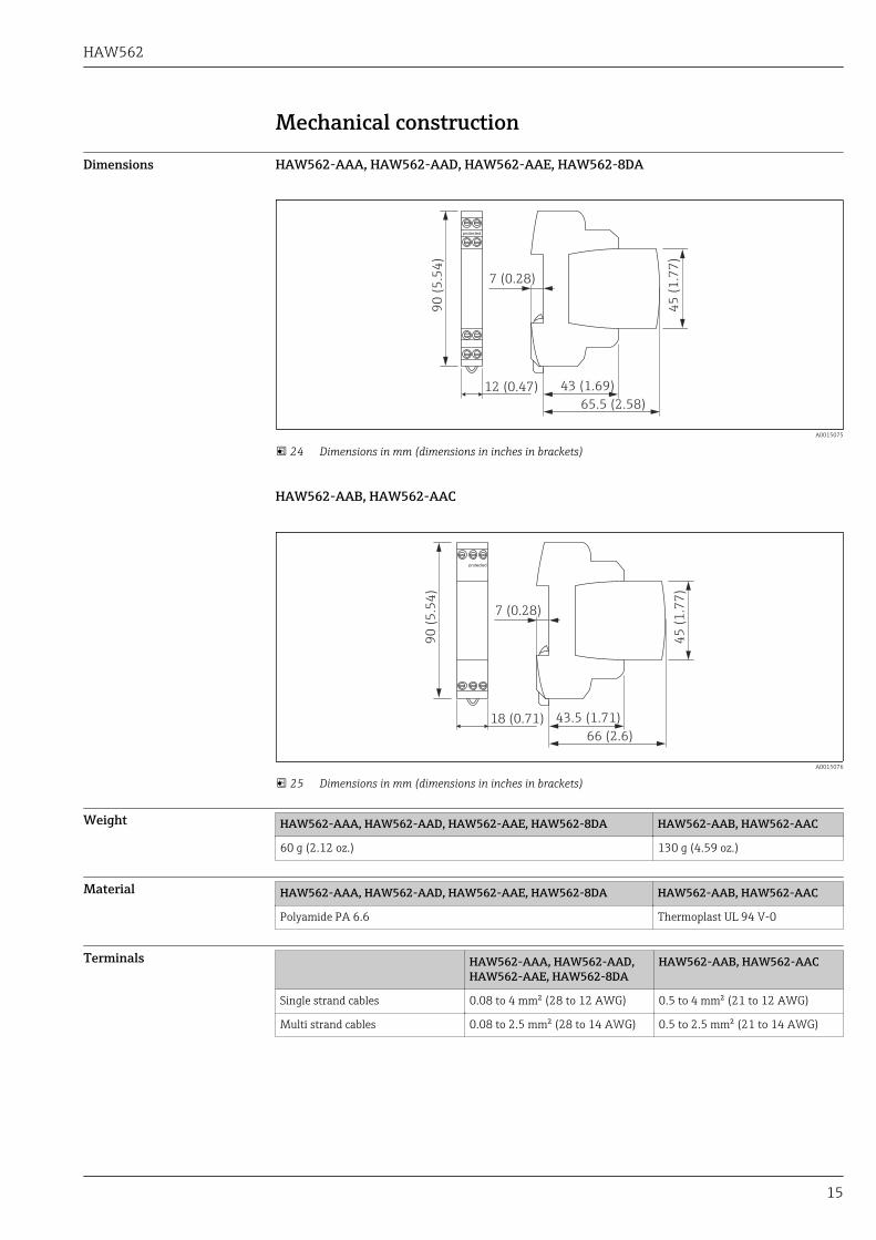
Installation
Installation instructions Mounting location
Installation on 35 mm top hat rail to EN 60715
A0015069
22 Installation on top hat rail, drawing as example
Multiple unit installation
A0015101
23 Multiple unit installation
Environment
Ambient temperature range –40 to +80 °C (–40 to +176 °F)
Humidity 5 to 95 %
Storage temperature See "Ambient temperature range"
Degree of protection IP 20
HAW562
15
Mechanical construction
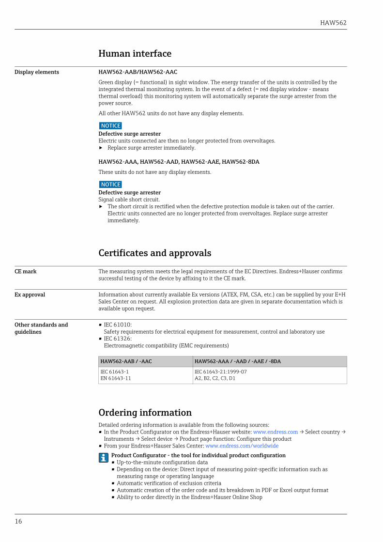
Dimensions HAW562-AAA, HAW562-AAD, HAW562-AAE, HAW562-8DA
90
(5
.54
)
12 (0.47)
7 (0.28)
43 (1.69)
45
(1
.77
)
65.5 (2.58)
A0015075
24 Dimensions in mm (dimensions in inches in brackets)
HAW562-AAB, HAW562-AAC
protected
90
(5
.54
)
18 (0.71)
7 (0.28)
43.5 (1.71)
45
(1
.77
)
66 (2.6)
A0015076
25 Dimensions in mm (dimensions in inches in brackets)
Weight HAW562-AAA, HAW562-AAD, HAW562-AAE, HAW562-8DA HAW562-AAB, HAW562-AAC
60 g (2.12 oz.) 130 g (4.59 oz.)
Material HAW562-AAA, HAW562-AAD, HAW562-AAE, HAW562-8DA HAW562-AAB, HAW562-AAC
Polyamide PA 6.6 Thermoplast UL 94 V-0
Terminals HAW562-AAA, HAW562-AAD,HAW562-AAE, HAW562-8DA
HAW562-AAB, HAW562-AAC
Single strand cables 0.08 to 4 mm² (28 to 12 AWG) 0.5 to 4 mm² (21 to 12 AWG)
Multi strand cables 0.08 to 2.5 mm² (28 to 14 AWG) 0.5 to 2.5 mm² (21 to 14 AWG)
HAW562
16
Human interface
Display elements HAW562-AAB/HAW562-AAC
Green display (= functional) in sight window. The energy transfer of the units is controlled by theintegrated thermal monitoring system. In the event of a defect (= red display window - meansthermal overload) this monitoring system will automatically separate the surge arrester from thepower source.
All other HAW562 units do not have any display elements.
NOTICEDefective surge arresterElectric units connected are then no longer protected from overvoltages.‣ Replace surge arrester immediately.
HAW562-AAA, HAW562-AAD, HAW562-AAE, HAW562-8DA
These units do not have any display elements.
NOTICEDefective surge arresterSignal cable short circuit.‣ The short circuit is rectified when the defective protection module is taken out of the carrier.
Electric units connected are no longer protected from overvoltages. Replace surge arresterimmediately.
Certificates and approvals
CE mark The measuring system meets the legal requirements of the EC Directives. Endress+Hauser confirmssuccessful testing of the device by affixing to it the CE mark.
Ex approval Information about currently available Ex versions (ATEX, FM, CSA, etc.) can be supplied by your E+HSales Center on request. All explosion protection data are given in separate documentation which isavailable upon request.
Other standards andguidelines
• IEC 61010:Safety requirements for electrical equipment for measurement, control and laboratory use
• IEC 61326:Electromagnetic compatibility (EMC requirements)
HAW562-AAB / -AAC HAW562-AAA / -AAD / -AAE / -8DA
IEC 61643-1EN 61643-11
IEC 61643-21:1999-07A2, B2, C2, C3, D1
Ordering informationDetailed ordering information is available from the following sources:• In the Product Configurator on the Endress+Hauser website: www.endress.com → Select country →
Instruments → Select device → Product page function: Configure this product• From your Endress+Hauser Sales Center: www.endress.com/worldwide
Product Configurator - the tool for individual product configuration• Up-to-the-minute configuration data• Depending on the device: Direct input of measuring point-specific information such as
measuring range or operating language• Automatic verification of exclusion criteria• Automatic creation of the order code and its breakdown in PDF or Excel output format• Ability to order directly in the Endress+Hauser Online Shop
HAW562
17
Accessories
Shield grounding terminal Only for HAW562-AAA, HAW562-AAD and HAW562-8DA, (→ 12).
Order as an additional option in the product structure for HAW562 or separately via order code:RK01-AN
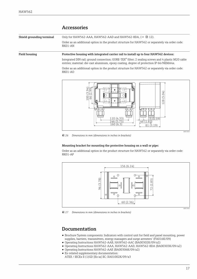
Field housing Protective housing with integrated carrier rail to install up to four HAW562 devices:
Integrated DIN rail; ground connection; GORE-TEX® filter; 2 sealing screws and 4 plastic M20 cableentries; material: die-cast aluminum, epoxy coating, degree of protection IP 66/NEMA4x.
Order as an additional option in the product structure for HAW562 or separately via order code:RK01-AO
10
0 (
3.9
4)
66
(2
.99
)
110 (4.33)146 (5.75)160 (6.3)
15 (0.59)46 (1.81)
81 (3.19)
12
8 (
5.0
4)
A0015043
26 Dimensions in mm (dimensions in inches in brackets)
Mounting bracket for mounting the protective housing on a wall or pipe:
Order as an additional option in the product structure for HAW562 or separately via order code:RK01-AP
156 (6.14)
72
(2
.83
)
96
(3
.78
)
60 (2.36)
A0015044
27 Dimensions in mm (dimensions in inches in brackets)
Documentation• Brochure 'System components: Indicators with control unit for field and panel mounting, power
supplies, barriers, transmitters, energy managers and surge arresters’ (FA016K/09)• Operating Instructions HAW562-AAB, HAW562-AAC (BA00302K/09/a2)• Operating Instructions HAW562-AAA, HAW562-AAD, HAW562-8DA (BA00303K/09/a2)• Operating Instructions HAW562-AAE (BA00306K/09/a2)• Ex-related supplementary documentation:
ATEX / IECEx II (1)GD [Ex ia] IIC: XA01002K/09/a3


www.addresses.endress.com