Embed Size (px)
Citation preview
OPTO 22 • 800-321-6786 • 1-951-695-3000 • www.opto22.com • [email protected]
© 2014–2018 Opto 22. All rights reserved. Dimensions and specifications are subject to change. Brand or product names used herein are trademarks or registered trademarks of their respective companies or organizations.
PAGE 1
DATA SHEETForm 2080-180808
HART SNAP I/O MODULES
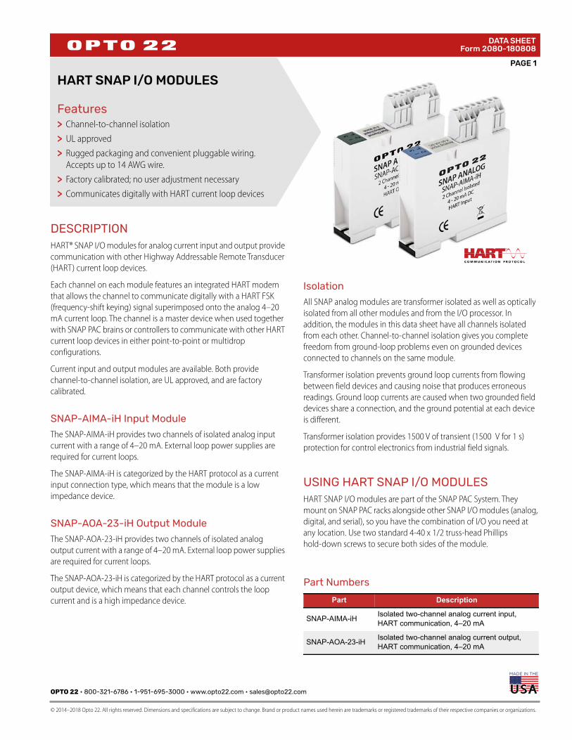
FeaturesChannel-to-channel isolation
UL approved
Rugged packaging and convenient pluggable wiring. Accepts up to 14 AWG wire.
Factory calibrated; no user adjustment necessary
Communicates digitally with HART current loop devices
DESCRIPTIONHART® SNAP I/O modules for analog current input and output provide
communication with other Highway Addressable Remote Transducer
(HART) current loop devices.
Each channel on each module features an integrated HART modem
that allows the channel to communicate digitally with a HART FSK
(frequency-shift keying) signal superimposed onto the analog 4–20
mA current loop. The channel is a master device when used together
with SNAP PAC brains or controllers to communicate with other HART
current loop devices in either point-to-point or multidrop
configurations.
Current input and output modules are available. Both provide
channel-to-channel isolation, are UL approved, and are factory
calibrated.
SNAP-AIMA-iH Input Module
The SNAP-AIMA-iH provides two channels of isolated analog input
current with a range of 4–20 mA. External loop power supplies are
required for current loops.
The SNAP-AIMA-iH is categorized by the HART protocol as a current
input connection type, which means that the module is a low
impedance device.
SNAP-AOA-23-iH Output Module
The SNAP-AOA-23-iH provides two channels of isolated analog
output current with a range of 4–20 mA. External loop power supplies
are required for current loops.
The SNAP-AOA-23-iH is categorized by the HART protocol as a current
output device, which means that each channel controls the loop
current and is a high impedance device.
Isolation
All SNAP analog modules are transformer isolated as well as optically
isolated from all other modules and from the I/O processor. In
addition, the modules in this data sheet have all channels isolated
from each other. Channel-to-channel isolation gives you complete
freedom from ground-loop problems even on grounded devices
connected to channels on the same module.
Transformer isolation prevents ground loop currents from flowing
between field devices and causing noise that produces erroneous
readings. Ground loop currents are caused when two grounded field
devices share a connection, and the ground potential at each device
is different.
Transformer isolation provides 1500 V of transient (1500 V for 1 s)
protection for control electronics from industrial field signals.
USING HART SNAP I/O MODULESHART SNAP I/O modules are part of the SNAP PAC System. They
mount on SNAP PAC racks alongside other SNAP I/O modules (analog,
digital, and serial), so you have the combination of I/O you need at
any location. Use two standard 4-40 x 1/2 truss-head Phillips
hold-down screws to secure both sides of the module.
>>>
>>
Part Numbers
Part Description
SNAP-AIMA-iH Isolated two-channel analog current input, HART communication, 4–20 mA
SNAP-AOA-23-iH Isolated two-channel analog current output, HART communication, 4–20 mA
PAGE 2
OPTO 22 • 800-321-6786 • 1-951-695-3000 • www.opto22.com • [email protected]
© 2014–2018 Opto 22. All rights reserved. Dimensions and specifications are subject to change. Brand or product names used herein are trademarks or registered trademarks of their respective companies or organizations.
DATA SHEETForm 2080-180808
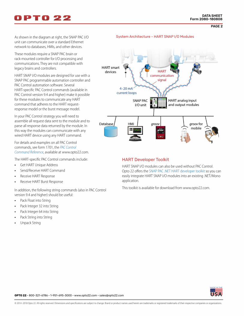
As shown in the diagram at right, the SNAP PAC I/O
unit can communicate over a standard Ethernet
network to databases, HMIs, and other devices.
These modules require a SNAP PAC brain or
rack-mounted controller for I/O processing and
communications. They are not compatible with
legacy brains and controllers.
HART SNAP I/O modules are designed for use with a
SNAP PAC programmable automation controller and
PAC Control automation software. Several
HART-specific PAC Control commands (available in
PAC Control version 9.4 and higher) make it possible
for these modules to communicate any HART
command that adheres to the HART request-
response model or the burst message model.
In your PAC Control strategy you will need to
assemble all request data sent to the module and to
parse all response data returned by the module. In
this way the modules can communicate with any
wired HART device using any HART command.
For details and examples on all PAC Control
commands, see form 1701, the PAC Control Command Reference, available at www.opto22.com.
The HART-specific PAC Control commands include:
• Get HART Unique Address
• Send/Receive HART Command
• Receive HART Response
• Receive HART Burst Response
In addition, the following string commands (also in PAC Control
version 9.4 and higher) should be useful:
• Pack Float into String
• Pack Integer 32 into String
• Pack Integer 64 into String
• Pack String into String
• Unpack String
HART Developer Toolkit
HART SNAP I/O modules can also be used without PAC Control.
Opto 22 offers the SNAP PAC .NET HART developer toolkit so you can
easily integrate HART SNAP I/O modules into an existing .NET/Mono
application.
This toolkit is available for download from www.opto22.com.
System Architecture - HART SNAP I/O Modules
OPTO 22 • 800-321-6786 • 1-951-695-3000 • www.opto22.com • [email protected]
© 2014–2018 Opto 22. All rights reserved. Dimensions and specifications are subject to change. Brand or product names used herein are trademarks or registered trademarks of their respective companies or organizations.
PAGE 3
DATA SHEETForm 2080-180808
LEDsEach module includes four LED indicators on the top of the module. LEDs 1 and 3 refer to channel 0; LEDs 2 and 4 refer to channel 1.
Specifications: SNAP-AIMA-iH Specifications: SNAP-AOA-23-iH
LED 1 or 2 Status
LED 3 or 4 Activity Description
Solid Green Blinking Green HART channel is operational; loop voltage and current are within limits.
Solid Red Blinking Red
HART communication error: • On a SNAP-AOA-23-iH, check loop voltage. Excessive load resistance or an incorrect loop
power supply may cause voltage to be too low.• On a SNAP-AIMA-iH, check loop current to make sure it is between 3.9 mA and 20.2 mA. NOTE: If loop voltage and current are correct, contact Product Support.
OFF -- Current loop open or loop voltage is zero. Implies that the channel is not being used.
Input Range NominalFull
4 to 20 mA 3.2 to 24 mA
Maximum Survivable Input 40 V or 160 mA
Impedance 230 Ohms nominal
Resolution 0.8 microamps
Accuracy +/- 10 microamps
Response Time(% of span/delta I/delta time) 99.9%/20.7mA/10 ms
Gain Temperature Coefficient 30 ppm/ °C
Offset Temperature Coefficient 15 ppm/ °C
DC Common Mode Rejection >-120 dB
AC Common Mode Rejection >-120 dB @ 60 Hz
Maximum Operating Common Mode Voltage
250 V continuous1500 V transient (1 s)
Isolation: Channel-Channel 250 V continuous1500 V transient (1 s)
Power Requirements 5 VDC (+/- 0.15) @ 150 mA
Ambient Temperature: Operating Storage
-20 °C to 70 °C-40 °C to 85 °C
Humidity 5-95%, non-condensing
Torque, hold-down screws 4 in-lb (0.45 N-m)
Torque, connector screws 5.26 in-lb (0.6 N-m)
Agency Approvals UL, CE, RoHS, DFARS
Warranty Lifetime
Output RangeNominalFull
4 to 20 mA3.2 to 24 mA
External Loop Voltage RangeNominal
12-36 VDC24 VDC
Maximum Load Resistance at Specified Loop Voltage12 VDC24 VDC36 VDC
300 Ohms850 Ohms1350 Ohms
Resolution 5 microamps
Accuracy +/- 20 microamps
Response Time(% of span/delta I/delta time) 99.9%/20.7 mA/400 ms
Gain Temperature Coefficient -50 ppm/ °C
Offset Temperature Coefficient -25 ppm/ °C
DC Common Mode Rejection >-120 dB
AC Common Mode Rejection >-120 dB @ 60 Hz
Maximum Operating Common Mode Voltage
250 V continuous1500 V transient (1 s)
Common Mode Resistance >1000 megohms
Isolation: Channel-Channel 250 V continuous1500 V transient (1 s)
Power Requirements 5 VDC (+/- 0.15) @ 150 mA
Ambient Temperature: Operating Storage
-20 °C to 70 °C-40 °C to 85 °C
Humidity 5-95%, non-condensing
Torque, hold-down screws 4 in-lb (0.45 N-m)
Torque, connector screws 5.26 in-lb (0.6 N-m)
Agency Approvals UL, CE, RoHS, DFARS
Warranty Lifetime
PAGE 4
OPTO 22 • 800-321-6786 • 1-951-695-3000 • www.opto22.com • [email protected]
© 2014–2018 Opto 22. All rights reserved. Dimensions and specifications are subject to change. Brand or product names used herein are trademarks or registered trademarks of their respective companies or organizations.
DATA SHEETForm 2080-180808
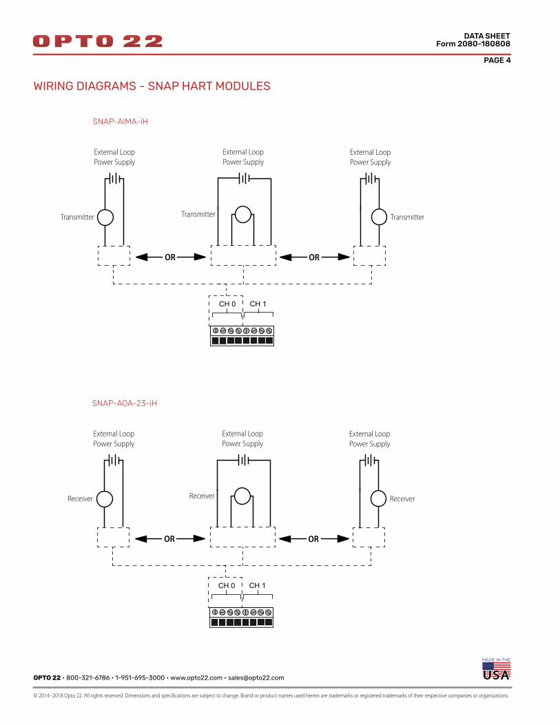
WIRING DIAGRAMS - SNAP HART MODULES
87654321
CH 0 CH 1
TTransmitter
+
+
–
–
External Loop
Power Supply
CH 01 2
Transmitter+
+
–
–
External Loop
Power Supply
CH 01 2 3 4
Transmitter
–
+
+
–
External Loop
Power Supply
CH 01 2
TT
OR OR
SNAP-AIMA-iH
87654321
CH 0 CH 1
RReceiver
+
+
–
–
External Loop
Power Supply
CH 01 2
Receiver+
+
–
–
External Loop
Power Supply
CH 01 2 3 4
Receiver
–
+
+
–
External Loop
Power Supply
CH 01 2
RR
OR OR
SNAP-AOA-23-iH
OPTO 22 • 800-321-6786 • 1-951-695-3000 • www.opto22.com • [email protected]
© 2014–2018 Opto 22. All rights reserved. Dimensions and specifications are subject to change. Brand or product names used herein are trademarks or registered trademarks of their respective companies or organizations.
PAGE 5
DATA SHEETForm 2080-180808
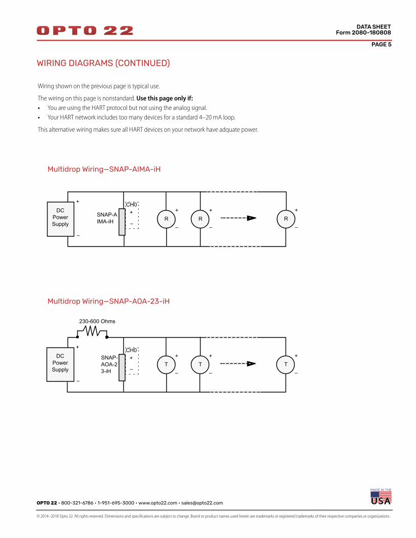
WIRING DIAGRAMS (CONTINUED)
Multidrop Wiring—SNAP-AIMA-iH
Wiring shown on the previous page is typical use.
The wiring on this page is nonstandard. Use this page only if:
• You are using the HART protocol but not using the analog signal.
• Your HART network includes too many devices for a standard 4–20 mA loop.
This alternative wiring makes sure all HART devices on your network have adquate power.
CH0+
–
+
–
+
–
SNAP-AIMA-iH
DC Power Supply
R+
–R
+
–R
Multidrop Wiring—SNAP-AOA-23-iH
CH0+
–
+
–
+
–
SNAP-AOA-23-iH
DC Power Supply
T+
–T
+
–T
230-600 Ohms
PAGE 6
OPTO 22 • 800-321-6786 • 1-951-695-3000 • www.opto22.com • [email protected]
© 2014–2018 Opto 22. All rights reserved. Dimensions and specifications are subject to change. Brand or product names used herein are trademarks or registered trademarks of their respective companies or organizations.
DATA SHEETForm 2080-180808
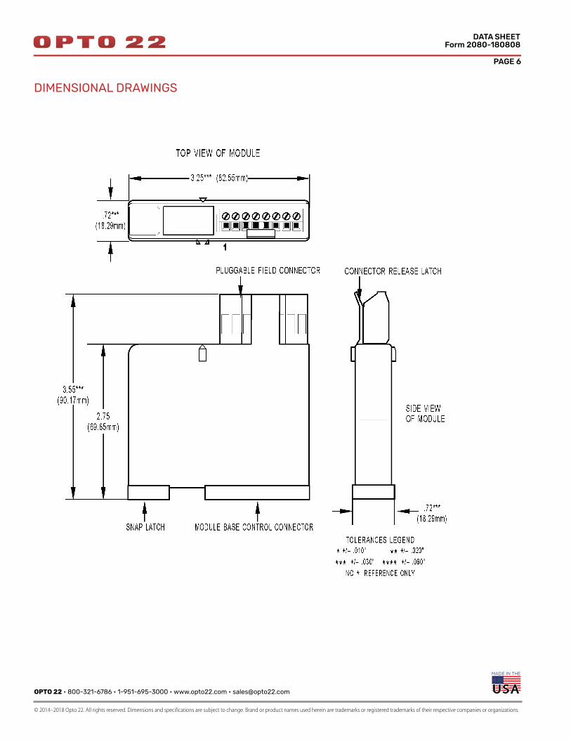
DIMENSIONAL DRAWINGS
PAGE 7
OPTO 22 • www.opto22.com SALES • [email protected] SUPPORT • [email protected] Business Park Dr. Temecula, CA 92590-3614 800-321-6786 • 1-951-695-3000 800-835-6786 • 1-951-695-3080
© 2014–2018 Opto 22. All rights reserved. Dimensions and specifications are subject to change. Brand or product names used herein are trademarks or registered trademarks of their respective companies or organizations.
DATA SHEETForm 2080-180808
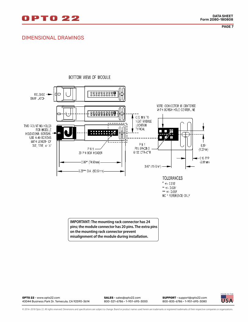
DIMENSIONAL DRAWINGS
IMPORTANT: The mounting rack connector has 24
pins; the module connector has 20 pins. The extra pins
on the mounting rack connector prevent
misalignment of the module during installation.
OPTO 22 • www.opto22.com SALES • [email protected] SUPPORT • [email protected] Business Park Dr. Temecula, CA 92590-3614 800-321-6786 • 1-951-695-3000 800-835-6786 • 1-951-695-3080
© 2006–2018 Opto 22. All rights reserved. Dimensions and specifications are subject to change. Brand or product names used herein are trademarks or registered trademarks of their respective companies or organizations.
More about Opto 22
Form 1335-180323
PRODUCTSOpto 22 develops and manufactures reliable, easy-to-use, open standards-based hardware and software products.
Industrial automation, process control, building automation, industrial refrigeration, remote monitoring, data acquisition, and industrial internet of things (IIoT) applications worldwide all rely on Opto 22.
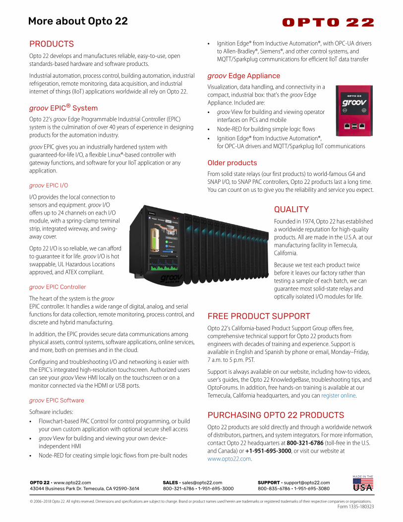
groov EPIC® System
Opto 22’s groov Edge Programmable Industrial Controller (EPIC) system is the culmination of over 40 years of experience in designing products for the automation industry.
groov EPIC gives you an industrially hardened system with guaranteed-for-life I/O, a flexible Linux®-based controller with gateway functions, and software for your IIoT application or any application.
groov EPIC I/O
I/O provides the local connection to sensors and equipment. groov I/O offers up to 24 channels on each I/O module, with a spring-clamp terminal strip, integrated wireway, and swing-away cover.
Opto 22 I/O is so reliable, we can afford to guarantee it for life. groov I/O is hot swappable, UL Hazardous Locations approved, and ATEX compliant.
groov EPIC Controller
The heart of the system is the groov EPIC controller. It handles a wide range of digital, analog, and serial functions for data collection, remote monitoring, process control, and discrete and hybrid manufacturing.
In addition, the EPIC provides secure data communications among physical assets, control systems, software applications, online services, and more, both on premises and in the cloud.
Configuring and troubleshooting I/O and networking is easier with the EPIC’s integrated high-resolution touchscreen. Authorized users can see your groov View HMI locally on the touchscreen or on a monitor connected via the HDMI or USB ports.
groov EPIC Software
Software includes:• Flowchart-based PAC Control for control programming, or build
your own custom application with optional secure shell access• groov View for building and viewing your own device-
independent HMI• Node-RED for creating simple logic flows from pre-built nodes
• Ignition Edge® from Inductive Automation®, with OPC-UA drivers to Allen-Bradley®, Siemens®, and other control systems, and MQTT/Sparkplug communications for efficient IIoT data transfer
groov Edge Appliance
Visualization, data handling, and connectivity in a compact, industrial box: that’s the groov Edge Appliance. Included are: • groov View for building and viewing operator
interfaces on PCs and mobile• Node-RED for building simple logic flows• Ignition Edge® from Inductive Automation®,
for OPC-UA drivers and MQTT/Sparkplug IIoT communications
Older products
From solid state relays (our first products) to world-famous G4 and SNAP I/O, to SNAP PAC controllers, Opto 22 products last a long time. You can count on us to give you the reliability and service you expect.
QUALITYFounded in 1974, Opto 22 has established a worldwide reputation for high-quality products. All are made in the U.S.A. at our manufacturing facility in Temecula, California.
Because we test each product twice before it leaves our factory rather than testing a sample of each batch, we can guarantee most solid-state relays and optically isolated I/O modules for life.
FREE PRODUCT SUPPORTOpto 22’s California-based Product Support Group offers free, comprehensive technical support for Opto 22 products from engineers with decades of training and experience. Support is available in English and Spanish by phone or email, Monday–Friday, 7 a.m. to 5 p.m. PST.
Support is always available on our website, including how-to videos, user’s guides, the Opto 22 KnowledgeBase, troubleshooting tips, and OptoForums. In addition, free hands-on training is available at our Temecula, California headquarters, and you can register online.
PURCHASING OPTO 22 PRODUCTSOpto 22 products are sold directly and through a worldwide network of distributors, partners, and system integrators. For more information, contact Opto 22 headquarters at 800-321-6786 (toll-free in the U.S. and Canada) or +1-951-695-3000, or visit our website at www.opto22.com.