Embed Size (px)
Citation preview
HART® Communicator
MAN 4275A00PN: 00275-8026-0001
EnglishJuly 2000
NOTICE
Read this manual before working with this product. For personal and system safety, and for optimum product performance, make sure you thoroughly understand the contents before using or servicing this product.
For equipment service needs, contact the nearest product representative.
Rosemount and SMART FAMILY are registered trademarks of Rosemount Inc.MINIGRABBER is a trademark of Pomona Electronics.
HART is a registered trademark of the HART Communication Foundation.
Product Manual for theHART Communicator
Fisher-Rosemount Systems8301 Cameron RoadAustin, TX 78754 USATechnical Support: 1-800-833-8314or (512) 832-3774Service: 1-800-654-7768www.hartcommunicator.com
MAN 4275A00 AW# 000701© Fisher-Rosemount Systems, Inc. 2000. All Rights Reserved.Printed in USA
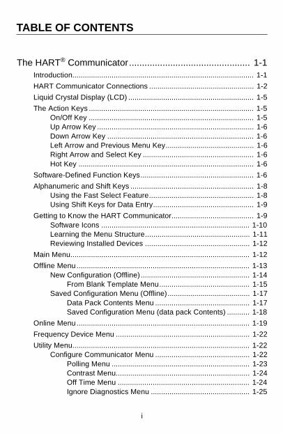
TABLE OF CONTENTS
The HART® Communicator............................................... 1-1Introduction........................................................................................ 1-1
HART Communicator Connections ................................................... 1-2
Liquid Crystal Display (LCD) ............................................................. 1-5
The Action Keys ................................................................................ 1-5On/Off Key ................................................................................ 1-5Up Arrow Key ............................................................................ 1-6Down Arrow Key ....................................................................... 1-6Left Arrow and Previous Menu Key........................................... 1-6Right Arrow and Select Key ...................................................... 1-6Hot Key ..................................................................................... 1-6
Software-Defined Function Keys....................................................... 1-6
Alphanumeric and Shift Keys ............................................................ 1-8Using the Fast Select Feature................................................... 1-8Using Shift Keys for Data Entry................................................. 1-9
Getting to Know the HART Communicator........................................ 1-9Software Icons ........................................................................ 1-10Learning the Menu Structure................................................... 1-11Reviewing Installed Devices ................................................... 1-12
Main Menu....................................................................................... 1-12
Offline Menu.................................................................................... 1-13New Configuration (Offline) ..................................................... 1-14
From Blank Template Menu............................................ 1-15Saved Configuration Menu (Offline)........................................ 1-17
Data Pack Contents Menu .............................................. 1-17Saved Configuration Menu (data pack Contents) ........... 1-18
Online Menu.................................................................................... 1-19
Frequency Device Menu ................................................................. 1-22
Utility Menu...................................................................................... 1-22Configure Communicator Menu .............................................. 1-22
Polling Menu ................................................................... 1-23Contrast Menu................................................................. 1-24Off Time Menu ................................................................ 1-24Ignore Diagnostics Menu ................................................ 1-25
i
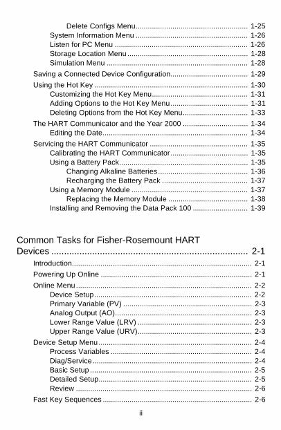
Delete Configs Menu....................................................... 1-25System Information Menu ....................................................... 1-26Listen for PC Menu ................................................................. 1-26Storage Location Menu ........................................................... 1-28Simulation Menu ..................................................................... 1-28
Saving a Connected Device Configuration...................................... 1-29
Using the Hot Key ........................................................................... 1-30Customizing the Hot Key Menu............................................... 1-31Adding Options to the Hot Key Menu...................................... 1-31Deleting Options from the Hot Key Menu................................ 1-33
The HART Communicator and the Year 2000 ................................ 1-34Editing the Date....................................................................... 1-34
Servicing the HART Communicator ................................................ 1-35Calibrating the HART Communicator...................................... 1-35Using a Battery Pack............................................................... 1-35
Changing Alkaline Batteries ............................................ 1-36Recharging the Battery Pack .......................................... 1-37
Using a Memory Module ......................................................... 1-37Replacing the Memory Module ....................................... 1-38
Installing and Removing the Data Pack 100 ........................... 1-39
Common Tasks for Fisher-Rosemount HARTDevices ............................................................................. 2-1
Introduction........................................................................................ 2-1
Powering Up Online .......................................................................... 2-1
Online Menu...................................................................................... 2-2Device Setup............................................................................. 2-2Primary Variable (PV) ............................................................... 2-3Analog Output (AO)................................................................... 2-3Lower Range Value (LRV) ........................................................ 2-3Upper Range Value (URV)........................................................ 2-3
Device Setup Menu........................................................................... 2-4Process Variables ..................................................................... 2-4Diag/Service.............................................................................. 2-4Basic Setup ............................................................................... 2-5Detailed Setup........................................................................... 2-5Review ...................................................................................... 2-6
Fast Key Sequences ......................................................................... 2-6
ii
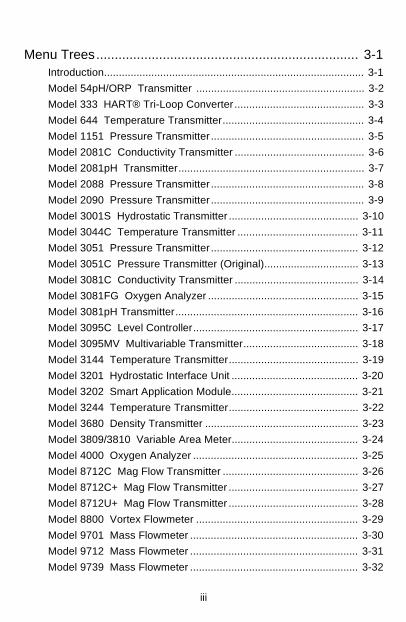
Menu Trees....................................................................... 3-1Introduction........................................................................................ 3-1
Model 54pH/ORP Transmitter ......................................................... 3-2
Model 333 HART® Tri-Loop Converter ............................................ 3-3
Model 644 Temperature Transmitter................................................ 3-4
Model 1151 Pressure Transmitter .................................................... 3-5
Model 2081C Conductivity Transmitter ............................................ 3-6
Model 2081pH Transmitter............................................................... 3-7
Model 2088 Pressure Transmitter .................................................... 3-8
Model 2090 Pressure Transmitter .................................................... 3-9
Model 3001S Hydrostatic Transmitter ............................................ 3-10
Model 3044C Temperature Transmitter ......................................... 3-11
Model 3051 Pressure Transmitter .................................................. 3-12
Model 3051C Pressure Transmitter (Original)................................ 3-13
Model 3081C Conductivity Transmitter .......................................... 3-14
Model 3081FG Oxygen Analyzer ................................................... 3-15
Model 3081pH Transmitter.............................................................. 3-16
Model 3095C Level Controller........................................................ 3-17
Model 3095MV Multivariable Transmitter....................................... 3-18
Model 3144 Temperature Transmitter............................................ 3-19
Model 3201 Hydrostatic Interface Unit ........................................... 3-20
Model 3202 Smart Application Module........................................... 3-21
Model 3244 Temperature Transmitter............................................ 3-22
Model 3680 Density Transmitter .................................................... 3-23
Model 3809/3810 Variable Area Meter........................................... 3-24
Model 4000 Oxygen Analyzer ........................................................ 3-25
Model 8712C Mag Flow Transmitter .............................................. 3-26
Model 8712C+ Mag Flow Transmitter ............................................ 3-27
Model 8712U+ Mag Flow Transmitter ............................................ 3-28
Model 8800 Vortex Flowmeter ....................................................... 3-29
Model 9701 Mass Flowmeter ......................................................... 3-30
Model 9712 Mass Flowmeter ......................................................... 3-31
Model 9739 Mass Flowmeter ......................................................... 3-32
iii
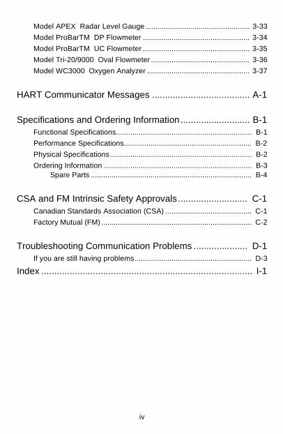
Model APEX Radar Level Gauge................................................... 3-33
Model ProBarTM DP Flowmeter .................................................... 3-34
Model ProBarTM UC Flowmeter .................................................... 3-35
Model Tri-20/9000 Oval Flowmeter ................................................ 3-36
Model WC3000 Oxygen Analyzer .................................................. 3-37
HART Communicator Messages ...................................... A-1
Specifications and Ordering Information........................... B-1Functional Specifications.................................................................. B-1
Performance Specifications.............................................................. B-2
Physical Specifications..................................................................... B-2
Ordering Information ........................................................................ B-3Spare Parts .............................................................................. B-4
CSA and FM Intrinsic Safety Approvals........................... C-1Canadian Standards Association (CSA) .......................................... C-1
Factory Mutual (FM) ......................................................................... C-2
Troubleshooting Communication Problems ..................... D-1If you are still having problems......................................................... D-3
Index .................................................................................. I-1
iv
LIST OF ILLUSTRATIONSSection
Figure Number Title Page
1-1. The HART Communicator. .......................................................... 1-1
1-2. Rear Connection Panel with NiCad Recharger Jack. ................. 1-2
1-3. Connecting to the Transmitter Comm Terminals. ....................... 1-3
1-4. Connecting the HART Communicator to the Loop. ..................... 1-3
1-5. Connecting the HART Communicator with the Load Resistor. ... 1-4
1-6. HART Communicator Alphanumeric and Shift Keys. .................. 1-8
1-7. Quickly Accessing Menus. .......................................................... 1-8
1-8. Powering Up Offline or Online. .................................................. 1-10
1-9. Menu Icons and Associated Keys. ............................................ 1-10
1-10. Main Menu. ............................................................................... 1-12
1-11. Offline Menu Tree. .................................................................... 1-13
1-12. Offline Menu. ............................................................................. 1-14
1-13. From Blank Template Menu. ..................................................... 1-15
1-14. Edit Individually Menu. .............................................................. 1-15
1-15. Unit Variable Menu. ................................................................... 1-15
1-16. Save As... Menu. ....................................................................... 1-16
1-17. Location Menu. ......................................................................... 1-16
1-18. Saved Configuration Menu (Offline). ......................................... 1-17
1-19. Data Pack Contents Menu. ....................................................... 1-17
1-20. Saved Configuration Menu (data pack Contents). .................... 1-18
1-21. Online Menu. ............................................................................. 1-19
1-22. Generic Online Menu Tree. ....................................................... 1-21
1-23. Frequency Device Menu. .......................................................... 1-22
1-24. Utility Menu. .............................................................................. 1-22
1-25. Configure Communicator Menu. ............................................... 1-22
1-26. Polling Menu. ............................................................................ 1-23
1-27. Contrast Menu. .......................................................................... 1-24
1-28. Off Time Menu. ......................................................................... 1-24
1-29. Ignore Diagnostics Menu. ......................................................... 1-25
v
1-30. Delete Configurations Menu. ..................................................... 1-25
1-31. System Information Menu. ........................................................ 1-26
1-32. Listen for PC Menu. .................................................................. 1-26
1-33. Storage Location Menu. ............................................................ 1-28
1-34. Sample Hot Key Menu. ............................................................. 1-30
1-35. Hotkey Configuration Menu. ...................................................... 1-31
1-36. Adding a Hot Key Option. .......................................................... 1-32
1-37. Marking a Read-Only Hot Key Option. ...................................... 1-32
1-38. Hot Key Menu. .......................................................................... 1-32
1-39. Variable Display Option. ............................................................ 1-33
1-40. Deleting a Hot Key Option. ........................................................ 1-33
1-41. Date Menu. ............................................................................... 1-34
1-42. HART Communicator Exploded View. ...................................... 1-35
1-43. Battery Pack Removal. .............................................................. 1-36
1-44. Memory Module Replacement. ................................................. 1-38
1-45. Data Pack 100 Installation and Removal. ................................. 1-39
2-1. Online Menu. ............................................................................... 2-2
2-2. Device Setup Menu. .................................................................... 2-4
2-3. Diagnostics and Service Menu. ................................................... 2-4
2-4. Basic Setup Menu. ...................................................................... 2-5
2-5. Sample Fast Key Sequence. ....................................................... 2-6
LIST OF TABLES
Table Number Title Page
1-1. Function Key Labels. ................................................................... 1-7
1-2. Main Options for the PC AMS Interface .......................................1-27
vi
SECTION 1
The HART® CommunicatorINTRODUCTION
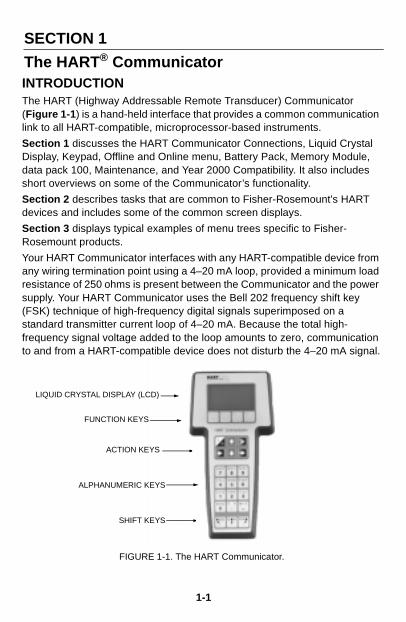
The HART (Highway Addressable Remote Transducer) Communicator (Figure 1-1) is a hand-held interface that provides a common communication link to all HART-compatible, microprocessor-based instruments.Section 1 discusses the HART Communicator Connections, Liquid Crystal Display, Keypad, Offline and Online menu, Battery Pack, Memory Module, data pack 100, Maintenance, and Year 2000 Compatibility. It also includes short overviews on some of the Communicator’s functionality.
Section 2 describes tasks that are common to Fisher-Rosemount’s HART devices and includes some of the common screen displays.
Section 3 displays typical examples of menu trees specific to Fisher-Rosemount products.
Your HART Communicator interfaces with any HART-compatible device from any wiring termination point using a 4–20 mA loop, provided a minimum load resistance of 250 ohms is present between the Communicator and the power supply. Your HART Communicator uses the Bell 202 frequency shift key (FSK) technique of high-frequency digital signals superimposed on a standard transmitter current loop of 4–20 mA. Because the total high-frequency signal voltage added to the loop amounts to zero, communication to and from a HART-compatible device does not disturb the 4–20 mA signal.
FIGURE 1-1. The HART Communicator.
FUNCTION KEYS
ACTION KEYS
ALPHANUMERIC KEYS
SHIFT KEYS
LIQUID CRYSTAL DISPLAY (LCD)
1-1
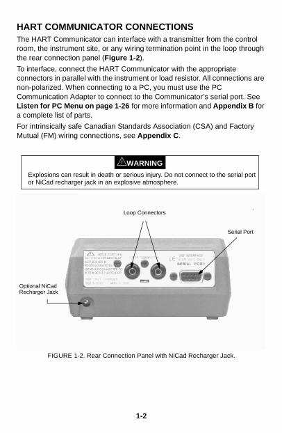
HART COMMUNICATOR CONNECTIONSThe HART Communicator can interface with a transmitter from the control room, the instrument site, or any wiring termination point in the loop through the rear connection panel (Figure 1-2).
To interface, connect the HART Communicator with the appropriate connectors in parallel with the instrument or load resistor. All connections are non-polarized. When connecting to a PC, you must use the PC Communication Adapter to connect to the Communicator’s serial port. See Listen for PC Menu on page 1-26 for more information and Appendix B for a complete list of parts.
For intrinsically safe Canadian Standards Association (CSA) and Factory Mutual (FM) wiring connections, see Appendix C.
FIGURE 1-2. Rear Connection Panel with NiCad Recharger Jack.
Explosions can result in death or serious injury. Do not connect to the serial port or NiCad recharger jack in an explosive atmosphere.
WARNING!
Serial Port
Loop Connectors
Optional NiCadRecharger Jack
1-2
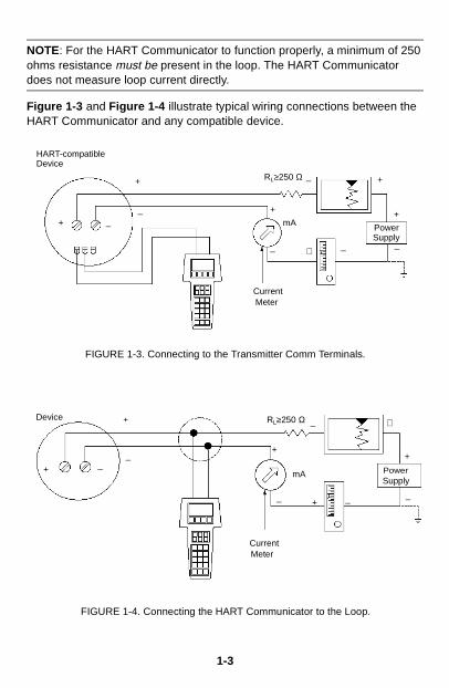
NOTE: For the HART Communicator to function properly, a minimum of 250 ohms resistance must be present in the loop. The HART Communicator does not measure loop current directly.
Figure 1-3 and Figure 1-4 illustrate typical wiring connections between the HART Communicator and any compatible device.
FIGURE 1-3. Connecting to the Transmitter Comm Terminals.
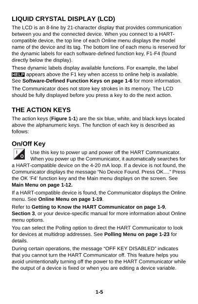
FIGURE 1-4. Connecting the HART Communicator to the Loop.
RL≥250 Ω
PowerSupply
+
_
+_
_
+
mA+ _
+
_
CurrentMeter
+ _
HART-compatibleDevice
_ +
PowerSupply
_+
+
_
CurrentMeter
_
+
RL≥250 Ω
_+
_
+Device
mA
1-3

Figure 1-5 shows how to connect the optional 250 ohm load resistor.
FIGURE 1-5. Connecting the HART Communicator with the Load Resistor.
Explosions can result in death or serious injury. Before connecting the HART Communicator in an explosive atmosphere, make sure the instruments in the loop are installed in accordance with intrinsically safe or nonincendive field wiring practices. For intrinsically safe CSA and FM wiring connections, see Appendix C.
WARNING!
HART-compatible Device
PowerSupply
+ –
Optional 250 Ohm Load Resistor
275-
0068
A, 0
275
B01
A
NOTE: To temporarily install the optional 250 ohm Load Resistor:1. Insert the load resistor into the lead set jacks.2. Open the loop to allow connection of the resistor in series in the loop.3. Close the loop using the lead set connectors.
–
+
1-4
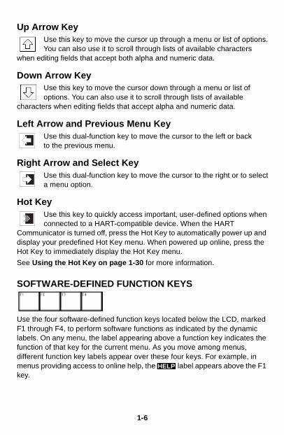
LIQUID CRYSTAL DISPLAY (LCD)The LCD is an 8-line by 21-character display that provides communication between you and the connected device. When you connect to a HART-compatible device, the top line of each Online menu displays the model name of the device and its tag. The bottom line of each menu is reserved for the dynamic labels for each software-defined function key, F1-F4 (found directly below the display).
These dynamic labels display available functions. For example, the label appears above the F1 key when access to online help is available.
See Software-Defined Function Keys on page 1-6 for more information.
The Communicator does not store key strokes in its memory. The LCD should be fully displayed before you press a key to do the next action.
THE ACTION KEYSThe action keys (Figure 1-1) are the six blue, white, and black keys located above the alphanumeric keys. The function of each key is described as follows:
On/Off KeyUse this key to power up and power off the HART Communicator.When you power up the Communicator, it automatically searches for
a HART-compatible device on the 4-20 mA loop. If a device is not found, the Communicator displays the message “No Device Found. Press OK....” Press the OK ‘F4’ function key and the Main menu displays on the screen. See Main Menu on page 1-12.
If a HART-compatible device is found, the Communicator displays the Online menu. See Online Menu on page 1-19.
Refer to Getting to Know the HART Communicator on page 1-9, Section 3, or your device-specific manual for more information about Online menu options.
You can select the Polling option to direct the HART Communicator to look for devices at multidrop addresses. See Polling Menu on page 1-23 for details.
During certain operations, the message “OFF KEY DISABLED” indicates that you cannot turn the HART Communicator off. This feature helps you avoid unintentionally turning off the power to the HART Communicator while the output of a device is fixed or when you are editing a device variable.
HELP
1-5
Up Arrow KeyUse this key to move the cursor up through a menu or list of options.You can also use it to scroll through lists of available characters
when editing fields that accept both alpha and numeric data.
Down Arrow KeyUse this key to move the cursor down through a menu or list ofoptions. You can also use it to scroll through lists of available
characters when editing fields that accept alpha and numeric data.
Left Arrow and Previous Menu KeyUse this dual-function key to move the cursor to the left or backto the previous menu.
Right Arrow and Select KeyUse this dual-function key to move the cursor to the right or to selecta menu option.
Hot KeyUse this key to quickly access important, user-defined options whenconnected to a HART-compatible device. When the HART
Communicator is turned off, press the Hot Key to automatically power up and display your predefined Hot Key menu. When powered up online, press the Hot Key to immediately display the Hot Key menu.
See Using the Hot Key on page 1-30 for more information.
SOFTWARE-DEFINED FUNCTION KEYS
Use the four software-defined function keys located below the LCD, marked F1 through F4, to perform software functions as indicated by the dynamic labels. On any menu, the label appearing above a function key indicates the function of that key for the current menu. As you move among menus, different function key labels appear over these four keys. For example, in menus providing access to online help, the label appears above the F1 key.
HELP
1-6
In menus providing access to the Home menu, the label appears above the F3 key. When the label displays, press F3 to return directly to the Online menu. Press (F3) to return to the screen from which
was pressed.
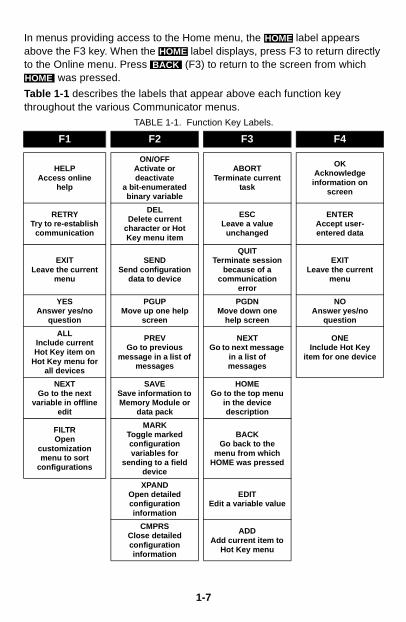
Table 1-1 describes the labels that appear above each function key throughout the various Communicator menus.
TABLE 1-1. Function Key Labels.
F1 F2 F3 F4
HELPAccess online
help
ON/OFFActivate or deactivate
a bit-enumerated binary variable
ABORTTerminate current
task
OKAcknowledge
information on screen
RETRYTry to re-establish
communication
DELDelete current
character or Hot Key menu item
ESCLeave a value
unchanged
ENTERAccept user-entered data
EXITLeave the current
menu
SENDSend configuration
data to device
QUITTerminate session
because of a communication
error
EXITLeave the current
menu
YESAnswer yes/no
question
PGUPMove up one help
screen
PGDNMove down one
help screen
NOAnswer yes/no
question
ALLInclude current Hot Key item on
Hot Key menu for all devices
PREVGo to previous
message in a list of messages
NEXTGo to next message
in a list of messages
ONEInclude Hot Key
item for one device
NEXTGo to the next
variable in offline edit
SAVESave information to Memory Module or
data pack
HOMEGo to the top menu
in the device description
FILTROpen
customization menu to sort
configurations
MARKToggle marked configuration variables for
sending to a field device
BACKGo back to the
menu from which HOME was pressed
XPANDOpen detailed configuration information
EDITEdit a variable value
CMPRSClose detailed configuration information
ADDAdd current item to
Hot Key menu
HOMEHOME
BACKHOME
1-7
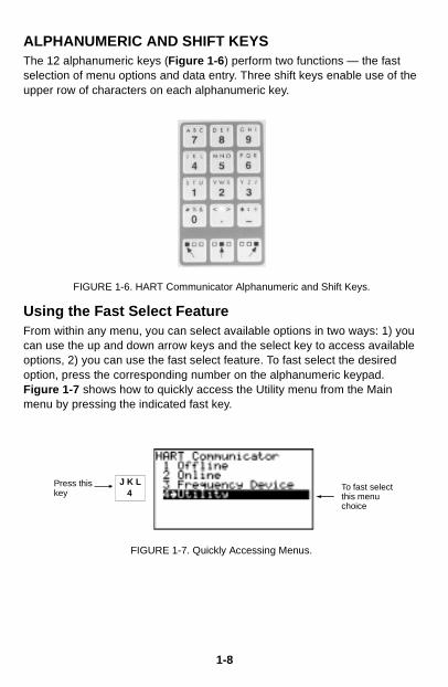
ALPHANUMERIC AND SHIFT KEYSThe 12 alphanumeric keys (Figure 1-6) perform two functions — the fast selection of menu options and data entry. Three shift keys enable use of the upper row of characters on each alphanumeric key.
FIGURE 1-6. HART Communicator Alphanumeric and Shift Keys.
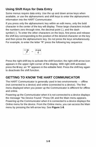
Using the Fast Select FeatureFrom within any menu, you can select available options in two ways: 1) you can use the up and down arrow keys and the select key to access available options, 2) you can use the fast select feature. To fast select the desired option, press the corresponding number on the alphanumeric keypad. Figure 1-7 shows how to quickly access the Utility menu from the Main menu by pressing the indicated fast key.
FIGURE 1-7. Quickly Accessing Menus.
4J K LPress this
keyTo fast select this menu choice
1-8
Using Shift Keys for Data EntrySome menus require data entry. Use the up and down arrow keys when available, or use the alphanumeric and shift keys to enter the alphanumeric information into the HART Communicator.
If you press only the alphanumeric key within an edit menu, only the bold character in the center of the key will display. These large characters include the numbers zero through nine, the decimal point (.), and the dash symbol (-). To enter the other characters on the keys, first press and release the shift key corresponding to the position of the desired character on the key and then press the alphanumeric key. Do not press the keys simultaneously. For example, to enter the letter “R” press the following key sequence:
→
Press the right shift key to activate the shift function; the right shift arrow icon appears in the upper right corner of the display. With right shift activated, press the 6 key; an “R” appears in the editable field. Press the shift key again to deactivate the shift function.
GETTING TO KNOW THE HART COMMUNICATORThe HART Communicator is generally used in two environments — offline (not connected to a device) and online (connected to a device). The first menu displayed when you power up the Communicator is different for offline and online.
Powering up the Communicator when it is not connected to a device displays the message “No Device Found.” Press OK and the Main menu appears. Powering up the Communicator when it is connected to a device displays the Online menu for the device. From the Online menu, you can access the Main menu by pressing the left-arrow key. See Figure 1-8.
6P Q R
1-9
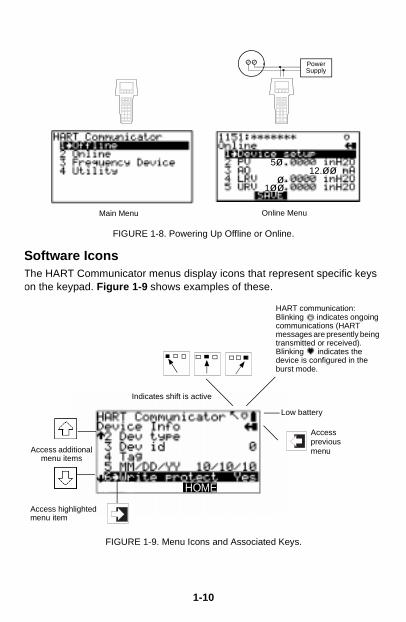
FIGURE 1-8. Powering Up Offline or Online.
Software IconsThe HART Communicator menus display icons that represent specific keys on the keypad. Figure 1-9 shows examples of these.
FIGURE 1-9. Menu Icons and Associated Keys.
Online MenuMain Menu
PowerSupply
5ø12.øø
ø1øø
Low battery
HART communication:Blinking indicates ongoing communications (HART messages are presently being transmitted or received). Blinking indicates the device is configured in the burst mode.
Access additional menu items
Accesspreviousmenu
HOME
Access highlighted menu item
Indicates shift is active
1-10
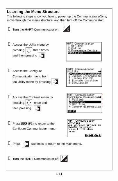
Learning the Menu StructureThe following steps show you how to power up the Communicator offline, move through the menu structure, and then turn off the Communicator:
➊ Turn the HART Communicator on.
➋ Access the Utility menu by
pressing three times
and then pressing
➌ Access the Configure
Communicator menu from
the Utility menu by pressing
➍ Access the Contrast menu by
pressing once and
then pressing
➎ Press (F3) to return to the
Configure Communicator menu.
➏ Press two times to return to the Main menu.
➐ Turn the HART Communicator off.
ESC
1-11
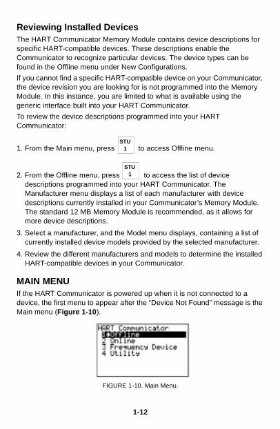
Reviewing Installed DevicesThe HART Communicator Memory Module contains device descriptions for specific HART-compatible devices. These descriptions enable the Communicator to recognize particular devices. The device types can be found in the Offline menu under New Configurations.
If you cannot find a specific HART-compatible device on your Communicator, the device revision you are looking for is not programmed into the Memory Module. In this instance, you are limited to what is available using the generic interface built into your HART Communicator.
To review the device descriptions programmed into your HART Communicator:
1. From the Main menu, press to access Offline menu.
2. From the Offline menu, press to access the list of devicedescriptions programmed into your HART Communicator. The Manufacturer menu displays a list of each manufacturer with device descriptions currently installed in your Communicator’s Memory Module. The standard 12 MB Memory Module is recommended, as it allows for more device descriptions.
3. Select a manufacturer, and the Model menu displays, containing a list of currently installed device models provided by the selected manufacturer.
4. Review the different manufacturers and models to determine the installed HART-compatible devices in your Communicator.
MAIN MENUIf the HART Communicator is powered up when it is not connected to a device, the first menu to appear after the “Device Not Found” message is the Main menu (Figure 1-10).
FIGURE 1-10. Main Menu.
1STU
1STU
1-12
If the Communicator is powered up when it is connected to a device, you can access the Main menu by pressing the previous menu key. Depending on the current online menu, you may need to press the previous menu key
several times or the key plus to return to the Main menu.
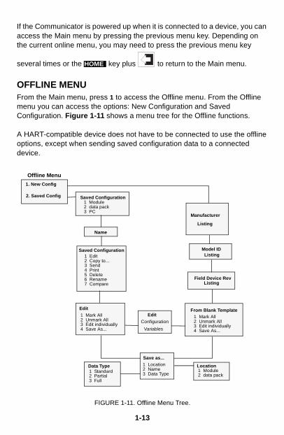
OFFLINE MENUFrom the Main menu, press 1 to access the Offline menu. From the Offline menu you can access the options: New Configuration and Saved Configuration. Figure 1-11 shows a menu tree for the Offline functions.
A HART-compatible device does not have to be connected to use the offline options, except when sending saved configuration data to a connected device.
FIGURE 1-11. Offline Menu Tree.
HOME
1 Edit2 Copy to...3 Send4 Print5 Delete6 Rename7 Compare
Offline Menu
Model ID
Field Device Rev
Manufacturer
1 Module2 data pack3 PC
Saved Configuration
1 Mark All2 Unmark All3 Edit individually4 Save As...
From Blank Template
Name
Saved Configuration
Edit1 Mark All2 Unmark All3 Edit individually4 Save As...
Configuration
Variables
Save as...1 Location2 Name3 Data Type1 Standard
2 Partial3 Full
Data Type Location1 Module2 data pack
Listing
1. New Config
2. Saved Config
Edit
Listing
Listing
1-13

New Configuration (Offline)Use this option to compile a custom set of device configuration data for downloading to any HART-compatible device. You can download repeatedly to multiple devices so that they store identical configuration data.
Offline configuration may not be available for all devices. Steps 2 and 3 below will help you verify if the desired manufacturer and device model are programmed into the Communicator’s Memory Module.
1. Press on the Main menu to access the Offline menu. This menu
allows you to enter a new device configuration or edit a saved device configuration.
To enter a new configuration, go to Step 2.
To edit a saved configuration, press 2 and go to Saved Configuration Menu (Offline) on page 1-17.
FIGURE 1-12. Offline Menu.
2. From the Offline menu, press 1. The Manufacturer menu displays a list of manufacturers with device descriptions currently installed in your HART Communicator.
3. Select a manufacturer; the Model menu displays. The Model menu contains a list of the currently installed device models provided by the manufacturer.
4. Select a device model for configuration; the Field Device Revision (Fld dev rev) menu displays. The Fld dev rev menu contains the currently installed software revisions for the field device and device descriptions (DD) for the model you selected from the previous screen.
5. Select a device revision; the From Blank Template menu (Figure 1-13) displays.
If you are unsure of the device revision, connect the HART Communicator to the device and determine its device revision level. You can access this information from the Online menu>Device Setup>Detailed Setup>Device Information. See your device manual for more information.
1STU
1-14
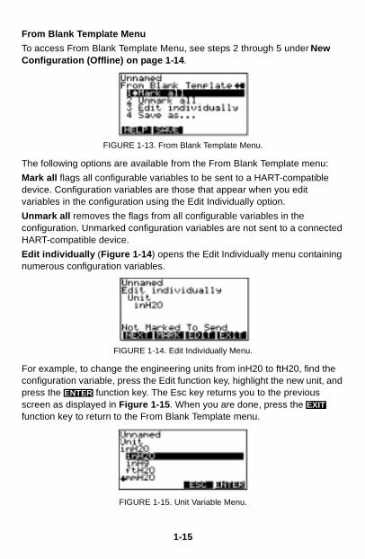
From Blank Template Menu
To access From Blank Template Menu, see steps 2 through 5 under New Configuration (Offline) on page 1-14.
FIGURE 1-13. From Blank Template Menu.
The following options are available from the From Blank Template menu:
Mark all flags all configurable variables to be sent to a HART-compatible device. Configuration variables are those that appear when you edit variables in the configuration using the Edit Individually option.
Unmark all removes the flags from all configurable variables in the configuration. Unmarked configuration variables are not sent to a connected HART-compatible device.
Edit individually (Figure 1-14) opens the Edit Individually menu containing numerous configuration variables.
FIGURE 1-14. Edit Individually Menu.
For example, to change the engineering units from inH20 to ftH20, find the configuration variable, press the Edit function key, highlight the new unit, and press the function key. The Esc key returns you to the previous screen as displayed in Figure 1-15. When you are done, press the function key to return to the From Blank Template menu.
FIGURE 1-15. Unit Variable Menu.
ENTEREXIT
1-15
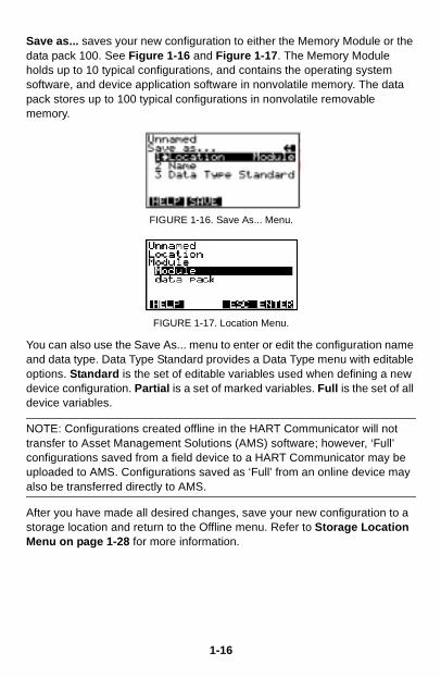
Save as... saves your new configuration to either the Memory Module or the data pack 100. See Figure 1-16 and Figure 1-17. The Memory Module holds up to 10 typical configurations, and contains the operating system software, and device application software in nonvolatile memory. The data pack stores up to 100 typical configurations in nonvolatile removable memory.
FIGURE 1-16. Save As... Menu.
FIGURE 1-17. Location Menu.
You can also use the Save As... menu to enter or edit the configuration name and data type. Data Type Standard provides a Data Type menu with editable options. Standard is the set of editable variables used when defining a new device configuration. Partial is a set of marked variables. Full is the set of all device variables.
NOTE: Configurations created offline in the HART Communicator will not transfer to Asset Management Solutions (AMS) software; however, ‘Full’ configurations saved from a field device to a HART Communicator may be uploaded to AMS. Configurations saved as ‘Full’ from an online device may also be transferred directly to AMS.
After you have made all desired changes, save your new configuration to a storage location and return to the Offline menu. Refer to Storage Location Menu on page 1-28 for more information.
1-16
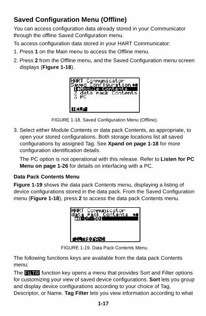
Saved Configuration Menu (Offline)You can access configuration data already stored in your Communicator through the offline Saved Configuration menu.
To access configuration data stored in your HART Communicator:
1. Press 1 on the Main menu to access the Offline menu.
2. Press 2 from the Offline menu, and the Saved Configuration menu screen displays (Figure 1-18).
FIGURE 1-18. Saved Configuration Menu (Offline).
3. Select either Module Contents or data pack Contents, as appropriate, to open your stored configurations. Both storage locations list all saved configurations by assigned Tag. See Xpand on page 1-18 for more configuration identification details.
The PC option is not operational with this release. Refer to Listen for PC Menu on page 1-26 for details on interfacing with a PC.
Data Pack Contents Menu
Figure 1-19 shows the data pack Contents menu, displaying a listing of device configurations stored in the data pack. From the Saved Configuration menu (Figure 1-18), press 2 to access the data pack Contents menu.
FIGURE 1-19. Data Pack Contents Menu.
The following functions keys are available from the data pack Contents menu:
The function key opens a menu that provides Sort and Filter options for customizing your view of saved device configurations. Sort lets you group and display device configurations according to your choice of Tag, Descriptor, or Name. Tag Filter lets you view information according to what
FILTR
1-17
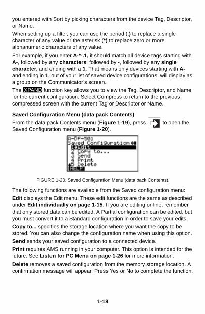
you entered with Sort by picking characters from the device Tag, Descriptor, or Name.
When setting up a filter, you can use the period (.) to replace a single character of any value or the asterisk (*) to replace zero or more alphanumeric characters of any value.
For example, if you enter A-*-.1, it should match all device tags starting with A-, followed by any characters, followed by -, followed by any single character, and ending with a 1. That means only devices starting with A- and ending in 1, out of your list of saved device configurations, will display as a group on the Communicator’s screen.
The function key allows you to view the Tag, Descriptor, and Name for the current configuration. Select Compress to return to the previous compressed screen with the current Tag or Descriptor or Name.
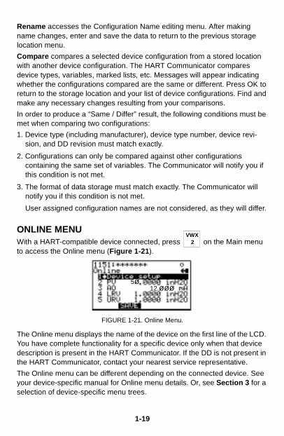
Saved Configuration Menu (data pack Contents)
From the data pack Contents menu (Figure 1-19), press to open the Saved Configuration menu (Figure 1-20).
FIGURE 1-20. Saved Configuration Menu (data pack Contents).
The following functions are available from the Saved configuration menu:
Edit displays the Edit menu. These edit functions are the same as described under Edit individually on page 1-15. If you are editing online, remember that only stored data can be edited. A Partial configuration can be edited, but you must convert it to a Standard configuration in order to save your edits.
Copy to... specifies the storage location where you want the copy to be stored. You can also change the configuration name when using this option.
Send sends your saved configuration to a connected device.
Print requires AMS running in your computer. This option is intended for the future. See Listen for PC Menu on page 1-26 for more information.
Delete removes a saved configuration from the memory storage location. A confirmation message will appear. Press Yes or No to complete the function.
XPAND
1-18
Rename accesses the Configuration Name editing menu. After making name changes, enter and save the data to return to the previous storage location menu.
Compare compares a selected device configuration from a stored location with another device configuration. The HART Communicator compares device types, variables, marked lists, etc. Messages will appear indicating whether the configurations compared are the same or different. Press OK to return to the storage location and your list of device configurations. Find and make any necessary changes resulting from your comparisons.
In order to produce a “Same / Differ” result, the following conditions must be met when comparing two configurations:
1. Device type (including manufacturer), device type number, device revi-sion, and DD revision must match exactly.
2. Configurations can only be compared against other configurations containing the same set of variables. The Communicator will notify you if this condition is not met.
3. The format of data storage must match exactly. The Communicator will notify you if this condition is not met.
User assigned configuration names are not considered, as they will differ.
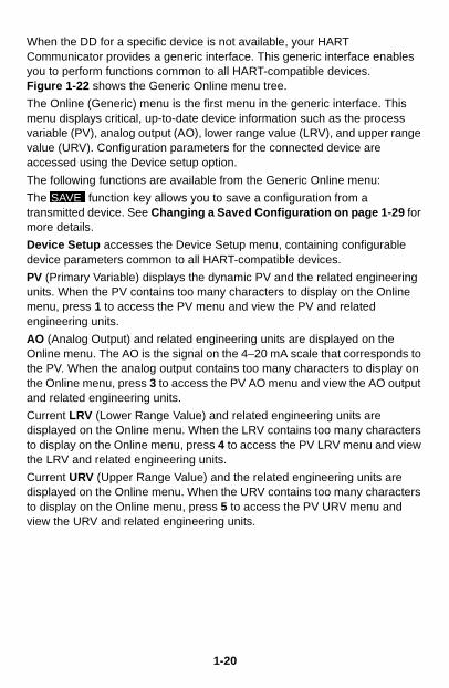
ONLINE MENUWith a HART-compatible device connected, press on the Main menu to access the Online menu (Figure 1-21).
FIGURE 1-21. Online Menu.
The Online menu displays the name of the device on the first line of the LCD. You have complete functionality for a specific device only when that device description is present in the HART Communicator. If the DD is not present in the HART Communicator, contact your nearest service representative.
The Online menu can be different depending on the connected device. See your device-specific manual for Online menu details. Or, see Section 3 for a selection of device-specific menu trees.
2VWX
5ø12.øøø
1-19
When the DD for a specific device is not available, your HART Communicator provides a generic interface. This generic interface enables you to perform functions common to all HART-compatible devices.Figure 1-22 shows the Generic Online menu tree.
The Online (Generic) menu is the first menu in the generic interface. This menu displays critical, up-to-date device information such as the process variable (PV), analog output (AO), lower range value (LRV), and upper range value (URV). Configuration parameters for the connected device are accessed using the Device setup option.
The following functions are available from the Generic Online menu:
The function key allows you to save a configuration from a transmitted device. See Changing a Saved Configuration on page 1-29 for more details.
Device Setup accesses the Device Setup menu, containing configurable device parameters common to all HART-compatible devices.
PV (Primary Variable) displays the dynamic PV and the related engineering units. When the PV contains too many characters to display on the Online menu, press 1 to access the PV menu and view the PV and related engineering units.
AO (Analog Output) and related engineering units are displayed on the Online menu. The AO is the signal on the 4–20 mA scale that corresponds to the PV. When the analog output contains too many characters to display on the Online menu, press 3 to access the PV AO menu and view the AO output and related engineering units.
Current LRV (Lower Range Value) and related engineering units are displayed on the Online menu. When the LRV contains too many characters to display on the Online menu, press 4 to access the PV LRV menu and view the LRV and related engineering units.
Current URV (Upper Range Value) and the related engineering units are displayed on the Online menu. When the URV contains too many characters to display on the Online menu, press 5 to access the PV URV menu and view the URV and related engineering units.
SAVE
1-20
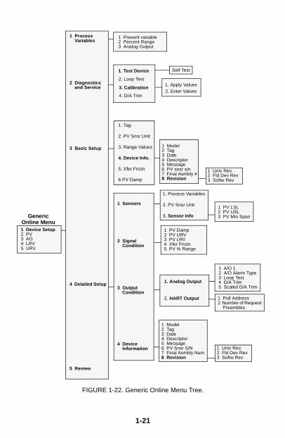
FIGURE 1-22. Generic Online Menu Tree.
1 Present variable2 Percent Range3 Analog Output
1 PV Damp2 PV URV3 PV LRV4 Xfer Fnctn5 PV % Range
1 Poll Address2 Number of Request
Preambles
1 Model2 Tag3 Date4 Descriptor5 Message6 PV snsr s/n7 Final Asmbly #8 Revision
1 A/O 12 A/O Alarm Type3 Loop Test4 D/A Trim5 Scaled D/A Trim
1 Device Setup2 PV3 AO4 LRV5 URV
1 Process Variables
2 Diagnostics and Service
3 Basic Setup
4 Detailed Setup
5 Review
1 Sensors
2 Signal Condition
3 Output Condition
4 Device Information
GenericOnline Menu
1. Test Device
2. Loop Test
3. Calibration1. Apply Values2. Enter Values
1. Tag
2. PV Snsr Unit
3. Range Values
4. Device Info.
5. Xfer Fnctn
6.PV Damp
1. Analog Output
2. HART Output
1 Model2 Tag3 Date4 Descriptor5 Message6 PV Snsr S/N7 Final Asmbly Num8 Revision
1. Process Variables
2. PV Snsr Unit
3. Sensor Info
4. D/A Trim
1 Univ Rev.2 Fld Dev Rev3 Softw Rev
Self Test
1 Univ Rev.2 Fld Dev Rev3 Softw Rev
1 PV LSL2 PV USL3 PV Min Span
1-21

FREQUENCY DEVICE MENU
From the Main menu, press to access the Frequency Device menu (Figure 1-23). This menu displays the frequency output and corresponding pressure output for the current-to-pressure devices. The output shown below was taken from device Model 3311.
FIGURE 1-23. Frequency Device Menu.
UTILITY MENUFrom the Main menu, press to access the Utility menu (Figure 1-24). The Utility menu provides access to functions that affect only the operation of the HART Communicator.
FIGURE 1-24. Utility Menu.
Configure Communicator MenuFrom the Utility menu, press 1 to access the Configure Communicator menu (Figure 1-25). Use this menu to set the polling, adjust the LCD contrast, set the Communicator off time, or set the number of ignore diagnostics messages.
FIGURE 1-25. Configure Communicator Menu.
3YZ /
4J K L
1-22
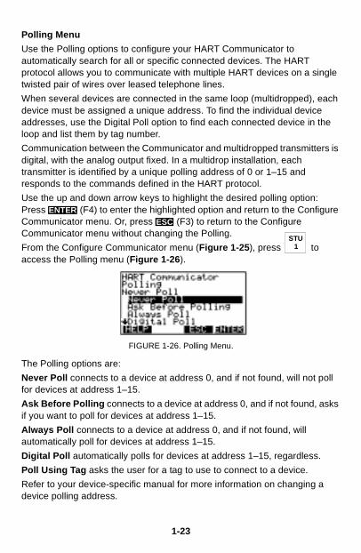
Polling Menu
Use the Polling options to configure your HART Communicator to automatically search for all or specific connected devices. The HART protocol allows you to communicate with multiple HART devices on a single twisted pair of wires over leased telephone lines.
When several devices are connected in the same loop (multidropped), each device must be assigned a unique address. To find the individual device addresses, use the Digital Poll option to find each connected device in the loop and list them by tag number.
Communication between the Communicator and multidropped transmitters is digital, with the analog output fixed. In a multidrop installation, each transmitter is identified by a unique polling address of 0 or 1–15 and responds to the commands defined in the HART protocol.
Use the up and down arrow keys to highlight the desired polling option: Press (F4) to enter the highlighted option and return to the Configure Communicator menu. Or, press (F3) to return to the Configure Communicator menu without changing the Polling.
From the Configure Communicator menu (Figure 1-25), press to access the Polling menu (Figure 1-26).
FIGURE 1-26. Polling Menu.
The Polling options are:
Never Poll connects to a device at address 0, and if not found, will not poll for devices at address 1–15.
Ask Before Polling connects to a device at address 0, and if not found, asks if you want to poll for devices at address 1–15.
Always Poll connects to a device at address 0, and if not found, will automatically poll for devices at address 1–15.
Digital Poll automatically polls for devices at address 1–15, regardless.
Poll Using Tag asks the user for a tag to use to connect to a device.
Refer to your device-specific manual for more information on changing a device polling address.
ENTERESC
1STU
1-23
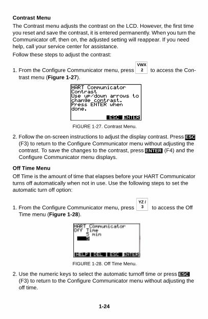
Contrast Menu
The Contrast menu adjusts the contrast on the LCD. However, the first time you reset and save the contrast, it is entered permanently. When you turn the Communicator off, then on, the adjusted setting will reappear. If you need help, call your service center for assistance.
Follow these steps to adjust the contrast:
1. From the Configure Communicator menu, press to access the Con-trast menu (Figure 1-27).
FIGURE 1-27. Contrast Menu.
2. Follow the on-screen instructions to adjust the display contrast. Press (F3) to return to the Configure Communicator menu without adjusting the contrast. To save the changes to the contrast, press (F4) and the Configure Communicator menu displays.
Off Time Menu
Off Time is the amount of time that elapses before your HART Communicator turns off automatically when not in use. Use the following steps to set the automatic turn off option:
1. From the Configure Communicator menu, press to access the Off Time menu (Figure 1-28).
FIGURE 1-28. Off Time Menu.
2. Use the numeric keys to select the automatic turnoff time or press (F3) to return to the Configure Communicator menu without adjusting the off time.
2VWX
ESC
ENTER
3YZ /
ESC
1-24
1-25
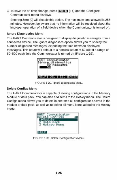
3. To save the off time change, press (F4) and the Configure Communicator menu displays.
Entering Zero (0) will disable this option. The maximum time allowed is 255 minutes. However, be aware that no information will be received about the improper operation of a field device when the Communicator is turned off.
Ignore Diagnostics Menu
The HART Communicator is designed to display diagnostic messages from a connected device. The Ignore diagnostics option allows you to specify the number of ignored messages, extending the time between displayed messages. This count will default to a nominal count of 50 out of a range of 50–500 each time the Communicator is turned on (Figure 1-29).
FIGURE 1-29. Ignore Diagnostics Menu.
Delete Configs Menu
The HART Communicator is capable of storing configurations in the Memory Module or data pack. You can also add items to the Hotkey menu. The Delete Configs menu allows you to delete in one step all configurations saved in the module or data pack, as well as to delete all menu items added to the Hotkey menu.
FIGURE 1-30. Delete Configurations Menu.
ENTER
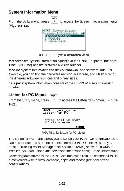
System Information Menu
From the Utility menu, press to access the System Information menu (Figure 1-31).
FIGURE 1-31. System Information Menu.
Motherboard system information consists of the Serial Peripheral Interface Time (SPI Time) and the firmware revision number.
Module system information consists of hardware and software data. For example, you can find the hardware revision, RAM size, and Flash size; or, the different software revisions and binary sizes.
data pack system information consists of the EEPROM size and revision number.
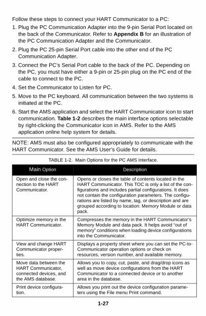
Listen for PC MenuFrom the Utility menu, press to access the Listen for PC menu (Figure 1-32).
FIGURE 1-32. Listen for PC Menu.
The Listen for PC menu allows you to set up your HART Communicator so it can accept data transfer and requests from the PC. On the PC side, you must be running Asset Management Solutions (AMS) software. If AMS is installed, you can upload and download the device configuration information.
Accessing data stored in the HART Communicator from the connected PC is a convenient way to view, compare, copy, and reconfigure field device configurations.
2VWX
3Y Z /
1-26
Follow these steps to connect your HART Communicator to a PC:
1. Plug the PC Communication Adapter into the 9-pin Serial Port located on the back of the Communicator. Refer to Appendix B for an illustration of the PC Communication Adapter and the Communicator.
2. Plug the PC 25-pin Serial Port cable into the other end of the PC Communication Adapter.
3. Connect the PC’s Serial Port cable to the back of the PC. Depending on the PC, you must have either a 9-pin or 25-pin plug on the PC end of the cable to connect to the PC.
4. Set the Communicator to Listen for PC.
5. Move to the PC keyboard. All communication between the two systems is initiated at the PC.
6. Start the AMS application and select the HART Communicator icon to start communication. Table 1-2 describes the main interface options selectable by right-clicking the Communicator icon in AMS. Refer to the AMS application online help system for details.
NOTE: AMS must also be configured appropriately to communicate with the HART Communicator. See the AMS User’s Guide for details.
TABLE 1-2. Main Options for the PC AMS Interface.
Main Option Description
Open and close the con-nection to the HART Communicator.
Opens or closes the table of contents located in the HART Communicator. This TOC is only a list of the con-figurations and includes partial configurations. It does not contain the configuration parameters. The configu-rations are listed by name, tag, or description and are grouped according to location: Memory Module or data pack.
Optimize memory in the HART Communicator.
Compresses the memory in the HART Communicator’s Memory Module and data pack. It helps avoid “out of memory” conditions when loading device configurations into the Communicator.
View and change HART Communicator proper-ties.
Displays a property sheet where you can set the PC-to-Communicator operation options or check on resources, version number, and available memory.
Move data between the HART Communicator, connected devices, and the AMS database.
Allows you to copy, cut, paste, and drag/drop icons as well as move device configurations from the HART Communicator to a connected device or to another area in the database.
Print device configura-tion.
Allows you print out the device configuration parame-ters using the File menu Print command.
1-27
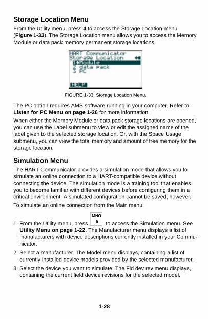
Storage Location MenuFrom the Utility menu, press 4 to access the Storage Location menu(Figure 1-33). The Storage Location menu allows you to access the Memory Module or data pack memory permanent storage locations.
FIGURE 1-33. Storage Location Menu.
The PC option requires AMS software running in your computer. Refer to Listen for PC Menu on page 1-26 for more information.
When either the Memory Module or data pack storage locations are opened, you can use the Label submenu to view or edit the assigned name of the label given to the selected storage location. Or, with the Space Usage submenu, you can view the total memory and amount of free memory for the storage location.
Simulation MenuThe HART Communicator provides a simulation mode that allows you to simulate an online connection to a HART-compatible device without connecting the device. The simulation mode is a training tool that enables you to become familiar with different devices before configuring them in a critical environment. A simulated configuration cannot be saved, however.
To simulate an online connection from the Main menu:
1. From the Utility menu, press to access the Simulation menu. See Utility Menu on page 1-22. The Manufacturer menu displays a list of manufacturers with device descriptions currently installed in your Commu-nicator.
2. Select a manufacturer. The Model menu displays, containing a list of currently installed device models provided by the selected manufacturer.
3. Select the device you want to simulate. The Fld dev rev menu displays, containing the current field device revisions for the selected model.
5MNO
1-28
4. To access the main configuration menu, select the applicable device revision. The Online menu for the simulated device is displayed. You can now use the HART Communicator as if it were connected to the selected device, and perform any online task.
If you are unsure of the device revision, connect the HART Communicator to the device and determine its device revision level. This information is most commonly accessed from Online menu>Device Setup>Detailed Setup>Device Information. For more information, see your device-specific manual.
SAVING A CONNECTED DEVICE CONFIGURATION Selecting the option from any Online menu allows you to save a configuration transmitted from a connected device to a permanent storage location.
To save, change, and send a stored configuration:
1. Select .
2. Enter a storage location (Memory Module or data pack).
3. Enter a Name and configuration Data Type. Name defaults to the online device Tag, and the Data Type defaults to Standard with all editable variables marked.
NOTE: Saved configurations have to be “Full” for storing in your PC in AMS software.
Warnings appear if there is not enough memory to store the transmitted configuration or if there is no list of configurable variables with Data Type set to standard.
The key disappears until you change any configuration data.
4. To change the configuration data, go into the Device Setup menu options and change the required data. For example, if the Tag needs to be changed, start with the Device Setup menu and go into the Basic Setup menu options, open Tag, and change the data.
Press to load the changed data, then press to send your changes to the connected device.
5. After each data configuration is sent, the function key appears. You have the option to save the individual variable or continue to change all of the variables and save them all at once.
SAVE
SAVE
SAVE
ENTER SEND
SAVE
1-29
6. If you choose not to data but want to continue, the key will reappear after each selection is entered.
7. Repeat the above process where necessary to modify each device configuration.
When saving a new configuration or changing a saved configuration offline, you will not encounter the send key.
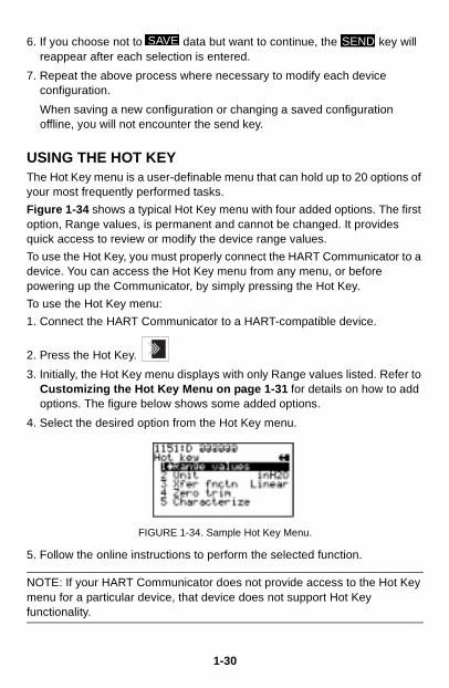
USING THE HOT KEYThe Hot Key menu is a user-definable menu that can hold up to 20 options of your most frequently performed tasks.
Figure 1-34 shows a typical Hot Key menu with four added options. The first option, Range values, is permanent and cannot be changed. It provides quick access to review or modify the device range values.
To use the Hot Key, you must properly connect the HART Communicator to a device. You can access the Hot Key menu from any menu, or before powering up the Communicator, by simply pressing the Hot Key.
To use the Hot Key menu:
1. Connect the HART Communicator to a HART-compatible device.
2. Press the Hot Key.
3. Initially, the Hot Key menu displays with only Range values listed. Refer to Customizing the Hot Key Menu on page 1-31 for details on how to add options. The figure below shows some added options.
4. Select the desired option from the Hot Key menu.
FIGURE 1-34. Sample Hot Key Menu.
5. Follow the online instructions to perform the selected function.
NOTE: If your HART Communicator does not provide access to the Hot Key menu for a particular device, that device does not support Hot Key functionality.
SAVE SEND
1-30
Customizing the Hot Key MenuYou can customize the Hot Key menu to provide fast access toRange values and your most frequently used tasks. Range values is
a permanent option providing quick access to rerange. This option cannot be deleted from the Hot Key menu.
Adding Options to the Hot Key MenuThe Hot Key menu has space for up to 20 online options. For example, if you have to change device tags and damping often, you can add these functions to the Hot Key menu. The HART Communicator automatically saves them so they can be quickly accessed by pressing the Hot Key. If you turn the unit off, then later turn it back on using the Hot Key, your customized menu will display.
With the Online menu or any of the submenu options open, use the following steps to add customized options to the Hot Key menu:
1. Using the up or down arrow key, move the menu bar to highlight the option you want to add to the Hot Key menu.
2. Press any one of the three shift keys, release it, and then press the Hot Key. This is shown in the following key sequence:
→
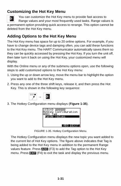
3. The Hotkey Configuration menu displays (Figure 1-35).
FIGURE 1-35. Hotkey Configuration Menu.
The Hotkey Configuration menu displays the new topic you want added to the current list of Hot Key options. The figure above indicates that Tag is being added to the Hot Key menu in addition to the permanent Range values feature. Press (F3) to add the Tag option to the Hot Key menu. Press (F4) to exit the task and display the previous menu.
ADDEXIT
1-31
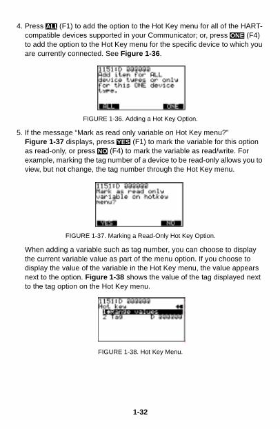
4. Press (F1) to add the option to the Hot Key menu for all of the HART-compatible devices supported in your Communicator; or, press (F4) to add the option to the Hot Key menu for the specific device to which you are currently connected. See Figure 1-36.
FIGURE 1-36. Adding a Hot Key Option.
5. If the message “Mark as read only variable on Hot Key menu?” Figure 1-37 displays, press (F1) to mark the variable for this option as read-only, or press (F4) to mark the variable as read/write. For example, marking the tag number of a device to be read-only allows you to view, but not change, the tag number through the Hot Key menu.
FIGURE 1-37. Marking a Read-Only Hot Key Option.
When adding a variable such as tag number, you can choose to display the current variable value as part of the menu option. If you choose to display the value of the variable in the Hot Key menu, the value appears next to the option. Figure 1-38 shows the value of the tag displayed next to the tag option on the Hot Key menu.
FIGURE 1-38. Hot Key Menu.
ALLONE
YESNO
1-32
6. Press (F1) to display the variable associated with the option on the Hot Key menu, or press (F4) to not display it. See Figure 1-39.
FIGURE 1-39. Variable Display Option.
7. Press (F4) on the Hot Key Configuration menu to complete the task. The options are now included on the Hot Key menu.
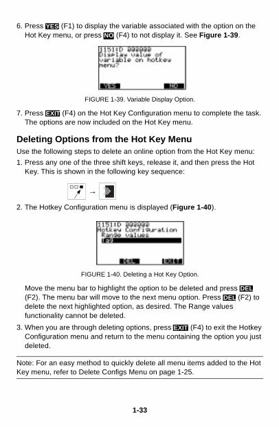
Deleting Options from the Hot Key MenuUse the following steps to delete an online option from the Hot Key menu:
1. Press any one of the three shift keys, release it, and then press the Hot Key. This is shown in the following key sequence:
→
2. The Hotkey Configuration menu is displayed (Figure 1-40).
FIGURE 1-40. Deleting a Hot Key Option.
Move the menu bar to highlight the option to be deleted and press (F2). The menu bar will move to the next menu option. Press (F2) to delete the next highlighted option, as desired. The Range values functionality cannot be deleted.
3. When you are through deleting options, press (F4) to exit the Hotkey Configuration menu and return to the menu containing the option you just deleted.
Note: For an easy method to quickly delete all menu items added to the Hot Key menu, refer to Delete Configs Menu on page 1-25.
YESNO
EXIT
DELDEL
EXIT
1-33
THE HART COMMUNICATOR AND THE YEAR 2000The HART Communicator is Year 2000 Compliant if the operating system is level 4.6 or greater. To determine the operating system level in your HART Communicator, turn it on. The first screen displays the “Module Rev”, which is the operating system level. If you need to update your operating system software, contact your nearest product representative.
NOTE: When you power up the Communicator, the Firmware Rev number appears first. A few seconds later, the Module Rev number displays one line below the Firmware Rev.
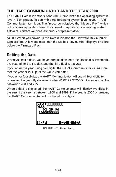
Editing the DateWhen you edit a date, you have three fields to edit: the first field is the month, the second field is the day, and the third field is the year.
If you enter the year using two digits, the HART Communicator will assume that the year is 1900 plus the value you enter.
If you enter four digits, the HART Communicator will use all four digits to represent the year. By definition in the HART PROTOCOL, the year must be between 1900 and 2155.
When a date is displayed, the HART Communicator will display two digits in the year if the year is between 1900 and 1999. If the year is 2000 or greater, the HART Communicator will display all four digits.
FIGURE 1-41. Date Menu.
1-34
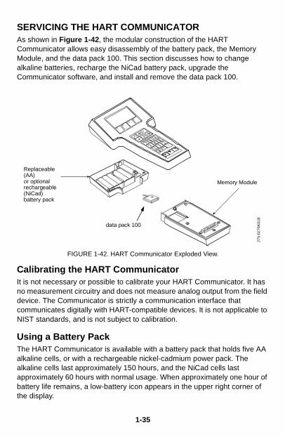
SERVICING THE HART COMMUNICATORAs shown in Figure 1-42, the modular construction of the HART Communicator allows easy disassembly of the battery pack, the Memory Module, and the data pack 100. This section discusses how to change alkaline batteries, recharge the NiCad battery pack, upgrade the Communicator software, and install and remove the data pack 100.
FIGURE 1-42. HART Communicator Exploded View.
Calibrating the HART CommunicatorIt is not necessary or possible to calibrate your HART Communicator. It has no measurement circuitry and does not measure analog output from the field device. The Communicator is strictly a communication interface that communicates digitally with HART-compatible devices. It is not applicable to NIST standards, and is not subject to calibration.
Using a Battery PackThe HART Communicator is available with a battery pack that holds five AA alkaline cells, or with a rechargeable nickel-cadmium power pack. The alkaline cells last approximately 150 hours, and the NiCad cells last approximately 60 hours with normal usage. When approximately one hour of battery life remains, a low-battery icon appears in the upper right corner of the display.
Memory Module
Replaceable (AA)or optional rechargeable (NiCad)battery pack
275-
0275
K01
B
data pack 100
1-35
Changing Alkaline Batteries
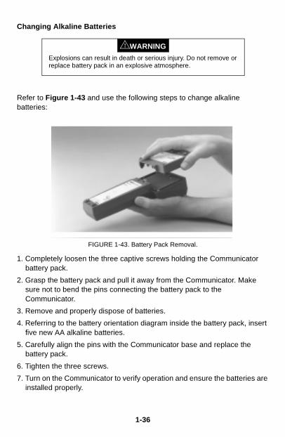
Refer to Figure 1-43 and use the following steps to change alkaline batteries:
FIGURE 1-43. Battery Pack Removal.
1. Completely loosen the three captive screws holding the Communicator battery pack.
2. Grasp the battery pack and pull it away from the Communicator. Make sure not to bend the pins connecting the battery pack to the Communicator.
3. Remove and properly dispose of batteries.
4. Referring to the battery orientation diagram inside the battery pack, insert five new AA alkaline batteries.
5. Carefully align the pins with the Communicator base and replace the battery pack.
6. Tighten the three screws.
7. Turn on the Communicator to verify operation and ensure the batteries are installed properly.
Explosions can result in death or serious injury. Do not remove or replace battery pack in an explosive atmosphere.
WARNING!
1-36

Recharging the Battery Pack
NiCad battery packs are shipped from the factory discharged. Prior to the first use, charge the battery pack while it is disconnected from the Communicator. Subsequent charges may be performed while using or storing the HART Communicator, without removing the battery pack.
NOTE: If the HART Communicator is stored for an extended period of time, or the battery pack becomes completely discharged, remove the battery pack from the Communicator and recharge it separately prior to using.
To recharge while using the Communicator, plug the recharger into an AC outlet or power source. To recharge while storing the Communicator, plug the recharger into an AC outlet or power source, make sure the HART Communicator is off, and charge for 16 hours. Overcharging will not harm the Communicator battery pack.
NOTE: For optimum performance, periodically discharge (use battery power until the low battery icon appears) and then fully recharge the battery pack.
Using a Memory ModuleThe HART Communicator is supplied with a replaceable Memory Module (Figure 1-44). A 12 MB Memory Module is the recommended standard.
The Memory Module is programmed to communicate with specific HART-compatible devices. Refer to Reviewing Installed Devices on page 1-12 to find the specific HART-compatible devices that are programmed into your Communicator’s Memory Module.
If you find that some specific devices are not listed in your Memory Module, contact your nearest service representative. Your Memory Module may be reprogrammed or replaced to include support for the required HART devices.
Explosions can result in death or serious injury. Do not recharge the NiCad battery pack in an explosive atmosphere.
WARNING!
1-37

Replacing the Memory Module
Refer to Figure 1-43 and Figure 1-44, and use the following steps to replace the Memory Module:
FIGURE 1-44. Memory Module Replacement.
1. Completely loosen the three captive screws holding the Communicator battery pack.
2. Grasp the battery pack and pull it straight up from the Communicator. Do not bend the battery pack’s connecting pins during the process.
3. Loosen the two captive screws holding the Memory Module.
4. Grasp the Memory Module and pull it away from the Communicator.
5. Align the new Memory Module with the Communicator, tighten the two screws, and replace the battery pack.
Explosions can result in death or serious injury. Do not remove or replace battery pack in an explosive atmosphere.
WARNING!
1-38
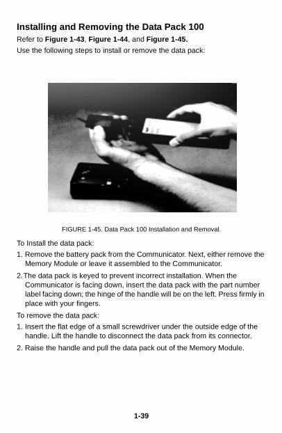
Installing and Removing the Data Pack 100Refer to Figure 1-43, Figure 1-44, and Figure 1-45.
Use the following steps to install or remove the data pack:
FIGURE 1-45. Data Pack 100 Installation and Removal.
To Install the data pack:
1. Remove the battery pack from the Communicator. Next, either remove the Memory Module or leave it assembled to the Communicator.
2.The data pack is keyed to prevent incorrect installation. When the Communicator is facing down, insert the data pack with the part number label facing down; the hinge of the handle will be on the left. Press firmly in place with your fingers.
To remove the data pack:
1. Insert the flat edge of a small screwdriver under the outside edge of the handle. Lift the handle to disconnect the data pack from its connector.
2. Raise the handle and pull the data pack out of the Memory Module.
1-39

1-40
SECTION 2Common Tasks for Fisher-Rosemount HARTDevices
INTRODUCTIONThis section displays HART Communicator menus and describes tasks common to Fisher-Rosemount HART products.
POWERING UP ONLINEPowering up online provides direct access to the Online menu. This menu provides critical data that is continuously updated. To be powered online, the Communicator must be connected to a 4–20 mA loop.
To power up the Communicator and access a HART compatible device:
1. Be sure the Communicator is connected to a HART compatible device. See HART Communicator Connections on page 1-2 for information about proper connections.
2. Power the Communicator by pressing the On/Off key.
NOTE: If a device is found, the HART Communicator displays the Online menu. If no device is found, the Communicator displays the Main menu. If no device is found, check the connections, verify the presence of the 250 ohms load resistance in series in the loop, and retry by selecting ‘Online.’ To poll multiple devices in the loop, refer to Polling Menu on page 1-23. For help on communication problems, see Appendix D.
2-1
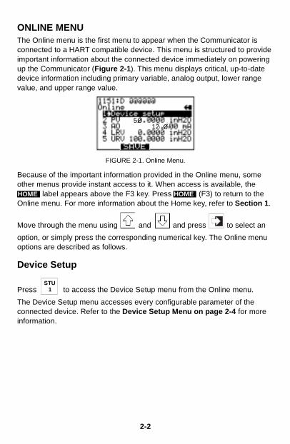
ONLINE MENUThe Online menu is the first menu to appear when the Communicator is connected to a HART compatible device. This menu is structured to provide important information about the connected device immediately on powering up the Communicator (Figure 2-1). This menu displays critical, up-to-date device information including primary variable, analog output, lower range value, and upper range value.
FIGURE 2-1. Online Menu.
Because of the important information provided in the Online menu, some other menus provide instant access to it. When access is available, the
label appears above the F3 key. Press (F3) to return to the Online menu. For more information about the Home key, refer to Section 1.
Move through the menu using and and press to select an
option, or simply press the corresponding numerical key. The Online menu options are described as follows.
Device Setup
Press to access the Device Setup menu from the Online menu.
The Device Setup menu accesses every configurable parameter of the connected device. Refer to the Device Setup Menu on page 2-4 for more information.
125ø
ø
HOME HOME
1STU
2-2
Primary Variable (PV)
Press to access Primary Variable.
The Online menu displays critical process information that is continuously updated. If the PV and related engineering units are too long, they will not appear on the Online menu. Select PV to view primary variable and the related engineering units.
Analog Output (AO)
Press to access Analog Output.
The analog output is the signal on the 4–20 mA scale that corresponds to the primary variable. When the AO contains too many characters to display on the Online menu, select AO to view the analog output and related engineering units.
Lower Range Value (LRV)
Press to access Lower Range Value.
Select LRV to view the lower range value and related engineering units.
Upper Range Value (URV)
Press to access Upper Range Value.
Select URV to view the upper range value and related engineering units.
2VWX
3YZ /
4J K L
5MNO
2-3
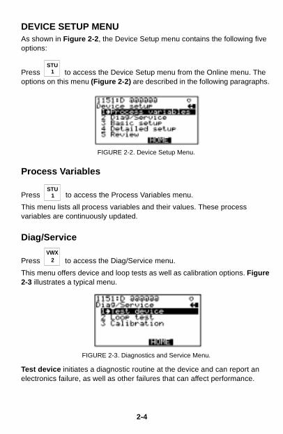
DEVICE SETUP MENUAs shown in Figure 2-2, the Device Setup menu contains the following five options:
Press to access the Device Setup menu from the Online menu. The options on this menu (Figure 2-2) are described in the following paragraphs.
FIGURE 2-2. Device Setup Menu.
Process Variables
Press to access the Process Variables menu.
This menu lists all process variables and their values. These process variables are continuously updated.
Diag/Service
Press to access the Diag/Service menu.
This menu offers device and loop tests as well as calibration options. Figure 2-3 illustrates a typical menu.
FIGURE 2-3. Diagnostics and Service Menu.
Test device initiates a diagnostic routine at the device and can report an electronics failure, as well as other failures that can affect performance.
1STU
1STU
2VWX
2-4
Loop test can fix the transmitter output at a specified analog value, and can be used to test the integrity of the loop and the operation of indicators, recorders, or similar devices in the loop.
Calibration can include such operations as configuring output related parameters, performing a sensor trim, or performing an analog output trim.
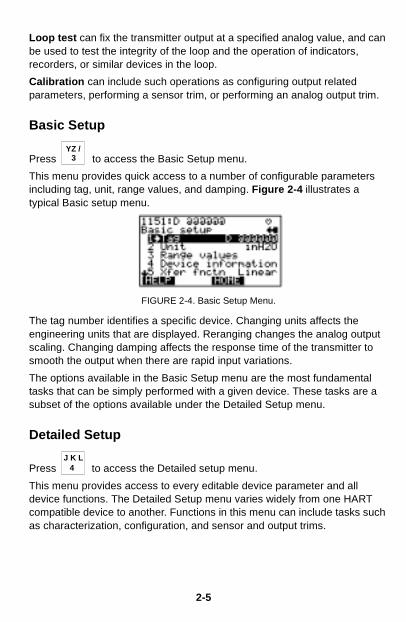
Basic Setup
Press to access the Basic Setup menu.
This menu provides quick access to a number of configurable parameters including tag, unit, range values, and damping. Figure 2-4 illustrates a typical Basic setup menu.
FIGURE 2-4. Basic Setup Menu.
The tag number identifies a specific device. Changing units affects the engineering units that are displayed. Reranging changes the analog output scaling. Changing damping affects the response time of the transmitter to smooth the output when there are rapid input variations.
The options available in the Basic Setup menu are the most fundamental tasks that can be simply performed with a given device. These tasks are a subset of the options available under the Detailed Setup menu.
Detailed Setup
Press to access the Detailed setup menu.
This menu provides access to every editable device parameter and all device functions. The Detailed Setup menu varies widely from one HART compatible device to another. Functions in this menu can include tasks such as characterization, configuration, and sensor and output trims.
3YZ /
4J K L
2-5
Review
Press to access the Review menu.
This menu lists all of the parameters stored in the connected device, including information about the measuring element, signal condition, and output. It also includes stored information about the connected device such as tag, materials of construction, and device software revision.
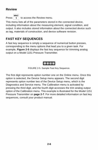
FAST KEY SEQUENCESA fast key sequence is simply a sequence of numerical button presses, corresponding to the menu options that lead you to a given task. For example, Figure 2-5 displays the fast key sequence for trimming analog output on a Model 1151 Pressure Transmitter.
The first digit represents option number one on the Online menu. Once this option is selected, the Device Setup menu appears. The second digit represents option number two of the Device Setup menu, which is the Diagnostics and Service menu. The Calibration menu is activated by pressing the third digit, and the fourth digit accesses the trim analog output option of the Calibration menu. This example is illustrated for the Model 1151 Pressure Transmitter on page 2-7. For more detailed information on fast key sequences, consult your product manual.
5MNO
1 2 3 2
FIGURE 2-5. Sample Fast Key Sequence.
2-6
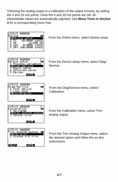
Trimming the analog output is a calibration of the output circuitry, by setting the 4 and 20 mA points. Once the 4 and 20 mA points are set, all intermediate values are automatically adjusted. See Menu Trees in Section 3 for a corresponding menu tree.
From the Online menu, select Device setup.
From the Device setup menu, select Diag/Service.
From the Diag/Service menu, select Calibration.
From the Calibration menu, select Trim analog output.
From the Trim Analog Output menu, select the desired option and follow the on-line instructions.
1250
0
2-7

2-8
SECTION 3
Menu Trees
INTRODUCTIONThis section displays typical examples of menu trees for specific Fisher-Rosemount products.
Menu trees show the primary commands and options available when using a sequence of menu selections. Text displayed in all bold capital letters in the menu trees indicates a progression to the next level. Due to space limitations, all levels may not be shown. Also note that your specific device could be different from the example shown. Consult your product manual for more detailed information.
The menu trees are identified by product and model number at the top of the page and are arranged in numeric-alpha order.
3-1
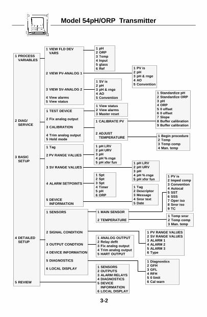
Model 54pH/ORP Transmitter
3-2
1 VIEW FLD DEVVARS
2 VIEW PV-ANALOG 1
3 VIEW SV-ANALOG 2
4 View alarms5 View status
1 MAIN SENSOR
2 TEMPERATURE
1 PV is2 Imped comp3 Convention4 Autocal5 SST6 SSS7 Oper iso8 Snsr iso9 TC
1 PV is2 pH3 pH & rnge4 AO5 Convention
1 pH2 ORP3 Temp4 Input5 glass6 Ref
1 PROCESSVARIABLES
2 DIAG/SERVICE
3 BASICSETUP
4 DETAILEDSETUP
5 REVIEW
1 Begin procedure2 Temp3 Temp comp4 Man. temp
1 Standardize pH2 Standardize ORP3 pH4 ORP5 0 offset6 0 offset7 Slope8 Buffer calibration9 Buffer calibration
1 Tag
2 PV RANGE VALUES
3 SV RANGE VALUES
4 ALARM SETPOINTS
5 DEVICEINFORMATION
1 TEST DEVICE
2 Fix analog output
3 CALIBRATION
4 Trim analog output5 Hold mode
1 View status2 View alarms3 Master reset
1 CALIBRATE PV
2 ADJUSTTEMPERATURE
1 pH LRV2 pH URV3 pH4 pH % rnge5 pH xfer fun
1 SV is2 pH3 pH & rnge4 AO5 Convention
1 Spt2 Spt3 Spt4 Timer5 pH6 ORP
1 Tag2 Descriptor3 Message4 Snsr text5 Date
1 SENSORS
2 SIGNAL CONDITION
3 OUTPUT CONDTION
4 DEVICE INFORMATION
5 DIAGNOSTICS
6 LOCAL DISPLAY
1 pH LRV2 pH URV3 pH4 pH % rnge5 pH xfer fun
1 ANALOG OUTPUT2 Relay deflt3 Fix analog output4 Trim analog output5 HART OUTPUT
1 Temp snsr2 Temp comp3 Man. temp
1 Diagnostics2 GFH3 GFL4 RFH5 0 limit6 Cal warn
1 PV RANGE VALUES2 SV RANGE VALUES3 ALARM 14 ALARM 25 ALARM 36 Type
1 SENSORS2 OUTPUTS3 ALARM RELAYS4 DIAGNOSTICS5 DEVICE
INFORMATION6 LOCAL DISPLAY
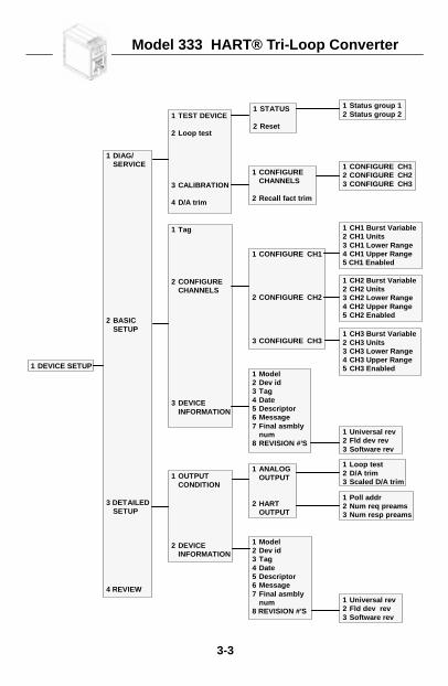
Model 333 HART® Tri-Loop Converter
3-3
1 DEVICE SETUP
1 DIAG/SERVICE
2 BASICSETUP
3 DETAILEDSETUP
4 REVIEW
1 TEST DEVICE
2 Loop test
3 CALIBRATION
4 D/A trim
1 Tag
2 CONFIGURECHANNELS
3 DEVICEINFORMATION
1 OUTPUTCONDITION
2 DEVICEINFORMATION
1 STATUS
2 Reset
1 CONFIGURECHANNELS
2 Recall fact trim
1 CONFIGURE CH12 CONFIGURE CH23 CONFIGURE CH3
1 Model2 Dev id3 Tag4 Date5 Descriptor6 Message7 Final asmbly
num8 REVISION #’S
1 ANALOGOUTPUT
2 HARTOUTPUT
1 Model2 Dev id3 Tag4 Date5 Descriptor6 Message7 Final asmbly
num8 REVISION #’S
1 Universal rev2 Fld dev rev3 Software rev
1 Loop test2 D/A trim3 Scaled D/A trim
1 Universal rev2 Fld dev rev3 Software rev
1 CONFIGURE CH1
2 CONFIGURE CH2
3 CONFIGURE CH3
1 CH1 Burst Variable2 CH1 Units3 CH1 Lower Range4 CH1 Upper Range5 CH1 Enabled
1 CH2 Burst Variable2 CH2 Units3 CH2 Lower Range4 CH2 Upper Range5 CH2 Enabled
1 CH3 Burst Variable2 CH3 Units3 CH3 Lower Range4 CH3 Upper Range5 CH3 Enabled
1 Status group 12 Status group 2
1 Poll addr2 Num req preams3 Num resp preams
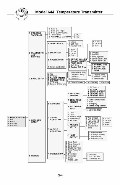
Model 644 Temperature Transmitter
3-4
1 PROCESS SENSOR
2 TERM TEMP SENSOR
3 A/D CONVR INFO
1 Poll Address2 # Reqst Preams3 Burst Mode4 Burst Options
1 DEVICE SETUP2 PV3 PV AO4 PV LRV5 PV URV
1 PROCESS VARIABLES
2 DIAGNOSTIC AND SERVICE
3 BASIC SETUP
4 DETAILED SETUP
5 REVIEW
1 SENSORS
2 SIGNAL CONDITION
3 OUTPUT CONDITION
4 DEVICE INFO
1 ANALOG OUTPUT
2 HART OUTPUT
1 LRV2 URV3 Snsr % Rnge4 Snsr Damp5 Xfr Funt
1 Status2 Self Test3 Master Test
1 4 ma2 20 ma3 Other4 End
1 A/O Output2 A/O Alrm Type3 LOOP TEST4 D/A Trim5 Scaled D/A
Trim
1 Term Temperature2 Unit3 Damping4 Term Temp Limits
1 PV2 SV
1 PV LRV2 PV URV3 PV Eng Units4 Lower Snsr Lmts5 Upper Snsr Lmt
1 PV Snsr 12 PV Unit3 SENSOR SETUP4 SENSOR INFO5 SENSOR TRIM
1 Unit Rev2 Fld Dev Rev3 Software rev
1 Snsr 12 Snsr 1 % Rnge3 Snsr 1 A/O Output4 Term Temp5 VARIABLE MAPPING
1 Differential Temp2 Terminal Temp3 Sensor 14 Sensor 2
1 TEST DEVICE
2 LOOP TEST
3 CALIBRATION
4 Smart Calibration
1 APPLLY VALUES2 RANGE VALUES3 SNRS TRIM4 D/A Trim5 Scaled D/A Trim
1 OHM/MV Trim2 SENOR REF3 RE-ENABLE
TRIM
1 Tag2 PV Unit3 RANGE VALUES4 CONNECTIONS5 PV Damp6 Sensor 1 Snsr s/n
1 Select Sensor 1 # of Wires
1 4 ma2 20 ma3 Other4 End
1 Snsr Type2 Snsr Connect3 Snsr 1 s/n4 50/60 Hz Filter5 Final Assembly6 Tag7 Descriptor8 message9 Date,
Model...etc.
1 50/60 Hz filter
1 4 ma2 20 ma3 Exit
1 Factory Trim2 Sensor 1 Trim3 Sensor Ref
1 PV Units
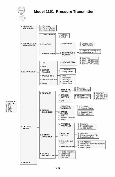
Model 1151 Pressure Transmitter
3-5
1 Pressure2 Percent Range3 Analog Output
1 Tag
2 Unit
3 RANGEVALUES
4 DEVICE INFO
5 Transfer Function
6 Damp
1 Self test2 Status
1 Keypad Input2 Apply Values
1 PROCESS VARIABLES
2 RANGE VALUES
3 Unit4 Transfer Function5 Damp
1 Loop Test2 Digital-to-Analog Trim3 Scaled D/A Trim
1 Poll Address2 Number of Request Preambles3 Burst Mode4 Burst Option
1 Digital-to-Analog Trim2 Scaled D/A Trim
1 Zero Trim2 Lower Sensor Trim3 Upper Sensor Trim4 Sensor Trim Points
1 Date2 Descriptor3 Message4 Write Protect5 Meter Type
1 Keypad Input2 Apply Values
1 Zero Trim2 Lwr Snsr Trim3 Upr Snsr Trim4 Trim Points
1 Pressure2 Percent Range
1 Keypad Input2 Apply Values
1 Pressure2 Percent Range3 Analog Output
1 Field Device Info2 Sensor Info3 Meter Type4 Self Test
1 DEVICE SETUP
2 PV3 AO4 LRV5 URV
1 PROCESS VARIABLES
2 DIAGNOSTICS AND SERVICE
3 BASIC SETUP
4 DETAILED SETUP
5 REVIEW
1 TEST DEVICE
2 Loop Test
3 CALIBRATION
1 RERANGE
2 TRIM ANALOG OUTPUT
3 SENSOR TRIM
1 SENSORS
2 SIGNAL CONDITION
3 OUTPUT CONDITION
4 DEVICE INFORMATION
1 Pressure2 Percent Range1 PROCESS
VARIABLES
2 SENSOR SERVICE
3 Unit
1 SENSOR TRIM2 Characterize
1 PROCESS VARIABLES
2 ANALOG OUTPUT
3 Analog Output Alarm
4 HART OUTPUT
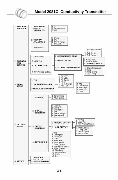
Model 2081C Conductivity Transmitter
3-6
1 Tag
2 PV RANGE VALUES
3 DEVICE INFORMATION
1 Poll Address2 Temp Unit3 Burst Option4 Burst Mode
1 PROCESS VARIABLE
2 DIAGNOS AND SERVICE
3 BASIC SETUP
4 DETAILED SETUP
5 REVIEW
1 SENSOR
2 SIGNAL CONDITION
3 OUTPUT CONDITION
4 DEVICE INFO
1 ANALOG OUTPUT
2 HART OUTPUT
1 C2 Temperature3 AC
1 VIEW FIELD DEVICE VARIABLES
2 VIEW PV-ANAOLOG 1
3 View Status
1 PV is2 PV3 PV % Range4 PV A/O
1 Begin Procedure2 C3 Cell Const4 Cell Factor
1 View Status
2 Loop Test
3 CALIBRATION
4 Trim Analog Output
1 STANDARDIZE COND
2 INITIAL SETUP
3 ADJUST TEMPERATURE
1 Temp Comp2 Man. Comp
1 pH LRV2 pH URV3 pH Damp4 pH5 pH % Range6 pH xfer fun
1 PV A/O2 Loop Test3 Trim Analog Output
1 Cell Const.2 Sensor Zero3 TEMP SLOPE CAL
1 Begin Procedure2 Temp3 Temp Comp4 Man. Temp
1 PV LRV2 PV URV3 PV Damp4 PV pH5 PV % Range6 Xfer Fun
1 Tag2 Descriptor3 Message4 Snsr Text5 Date
1 Tag2 Descriptor3 Message4 Date5 Snsr Text6 Burst Mode7 Burst Option8 Num Req Preams9 Write Protect10 Distributor11 Manufacturer12 Model13 etc.
1 SENSORS2 OUTPUTS3 DEVICE INFORM
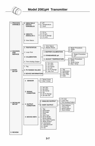
Model 2081pH Transmitter
3-7
1 Tag
2 PV RANGE VALUES
3 DEVICE INFORMATION
1 Poll Address2 Temp Unit3 Burst Option4 Burst Mode
1 PROCESS VARIABLE
2 DIAGNOS AND SERVICE
3 BASIC SETUP
4 DETAILED SETUP
5 REVIEW
1 SENSOR
2 SIGNAL CONDITION
3 OUTPUT CONDITION
4 DEVICE INFO
1 ANALOG OUTPUT
2 HART OUTPUT
1 pH2 Temperature3 Input
1 VIEW FIELD DEVICE VARIABLES
2 VIEW PV-ANAOLOG 1
3 View Status
1 PV is2 PV pH3 PV % Range4 PV A/O
1 Begin Procedure2 Slope3 pH
1 TEST/STATUS
2 Loop Test
3 CALIBRATION
4 Trim Analog Output
1 View Status2 Master Reset
1 BUFFER CALIBRATION
2 STANDARDIZE ph
3 ADJUST TEMPERATURE
1 Temp Comp2 Man. Comp
1 pH LRV2 pH URV3 pH Damp4 pH5 pH % Range6 pH xfer fun
1 PV A/O2 Loop Test3 Trim Analog Output
1 Begin Procedure2 pH
1 Begin Procedure2 Temp3 Temp Comp4 Man. Temp1 PV LRV
2 PV URV3 PV Damp4 PV pH5 PV % Range6 Xfer Fun
1 Tag2 Descriptor3 Message4 Snsr Text5 Date
1 Tag2 Descriptor3 Message4 Date5 Snsr Text6 Burst Mode7 Burst Option8 Num Req Preams9 Write Protect10 Distributor11 Manufacturer12 Model13 etc.
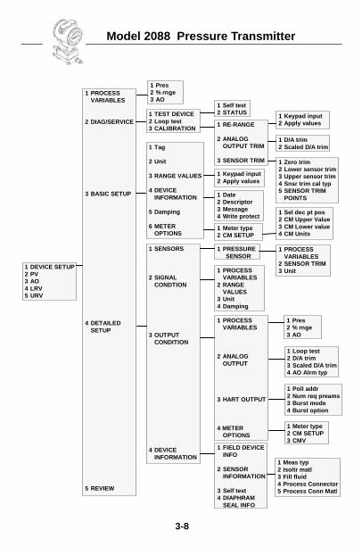
Model 2088 Pressure Transmitter
3-8
1 PROCESSVARIABLES
2 DIAG/SERVICE
3 BASIC SETUP
4 DETAILEDSETUP
5 REVIEW
1 DEVICE SETUP2 PV3 AO4 LRV5 URV
1 Pres2 % rnge3 AO
1 TEST DEVICE2 Loop test3 CALIBRATION
1 Self test2 STATUS 1 Keypad input
2 Apply values1 RE-RANGE
2 ANALOGOUTPUT TRIM
3 SENSOR TRIM
1 Tag
2 Unit
3 RANGE VALUES
4 DEVICEINFORMATION
5 Damping
6 METEROPTIONS
1 D/A trim2 Scaled D/A trim
1 Date2 Descriptor3 Message4 Write protect
1 Meter type2 CM SETUP
1 Zero trim2 Lower sensor trim3 Upper sensor trim4 Snsr trim cal typ5 SENSOR TRIM
POINTS
1 Keypad input2 Apply values
1 Sel dec pt pos2 CM Upper Value3 CM Lower value4 CM Units
1 SENSORS
2 SIGNALCONDTION
3 OUTPUTCONDITION
4 DEVICEINFORMATION
1 Pres2 % rnge3 AO
1 PRESSURESENSOR
1 PROCESSVARIABLES
2 SENSOR TRIM3 Unit
1 Loop test2 D/A trim3 Scaled D/A trim4 AO Alrm typ
1 PROCESSVARIABLES
2 RANGEVALUES
3 Unit4 Damping
1 PROCESSVARIABLES
2 ANALOGOUTPUT
3 HART OUTPUT
4 METEROPTIONS
1 Poll addr2 Num req preams3 Burst mode4 Burst option
1 Meter type2 CM SETUP3 CMV
1 FIELD DEVICEINFO
2 SENSORINFORMATION
3 Self test4 DIAPHRAM
SEAL INFO
1 Meas typ2 Isoltr matl3 Fill fluid4 Process Connector5 Process Conn Matl
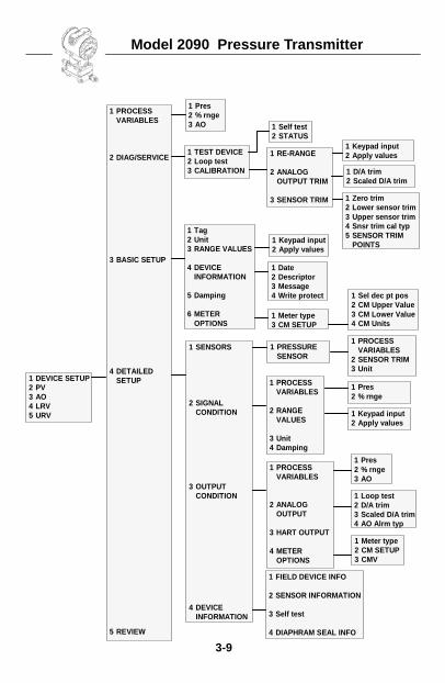
Model 2090 Pressure Transmitter
3-9
1 DEVICE SETUP2 PV3 AO4 LRV5 URV
1 PROCESSVARIABLES
2 DIAG/SERVICE
3 BASIC SETUP
4 DETAILEDSETUP
5 REVIEW
1 Zero trim2 Lower sensor trim3 Upper sensor trim4 Snsr trim cal typ5 SENSOR TRIM
POINTS
1 TEST DEVICE2 Loop test3 CALIBRATION
1 Pres2 % rnge3 AO 1 Self test
2 STATUS1 Keypad input2 Apply values
1 D/A trim2 Scaled D/A trim
1 RE-RANGE
2 ANALOGOUTPUT TRIM
3 SENSOR TRIM
1 Sel dec pt pos2 CM Upper Value3 CM Lower Value4 CM Units
1 PRESSURESENSOR
1 Meter type3 CM SETUP
1 Date2 Descriptor3 Message4 Write protect
1 Tag2 Unit3 RANGE VALUES
4 DEVICEINFORMATION
5 Damping
6 METEROPTIONS
1 Keypad input2 Apply values
1 SENSORS
2 SIGNALCONDITION
3 OUTPUTCONDITION
4 DEVICEINFORMATION
1 PROCESSVARIABLES
2 SENSOR TRIM3 Unit
1 PROCESSVARIABLES
2 RANGEVALUES
3 Unit4 Damping
1 PROCESSVARIABLES
2 ANALOGOUTPUT
3 HART OUTPUT
4 METEROPTIONS
1 Keypad input2 Apply values
1 Pres2 % rnge
1 Loop test2 D/A trim3 Scaled D/A trim4 AO Alrm typ
1 Pres2 % rnge3 AO
1 Meter type2 CM SETUP3 CMV
1 FIELD DEVICE INFO
2 SENSOR INFORMATION
3 Self test
4 DIAPHRAM SEAL INFO
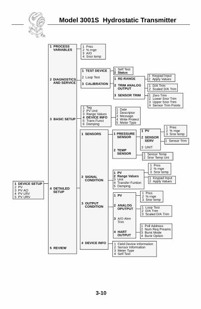
Model 3001S Hydrostatic Transmitter
3-10
1 Pres2 % rnge3 A/O4 Snsr temp
1 Tag2 PV Unit3 Range Values4 DEVICE INFO5 Trans Funct6 Damping
1 PV2 Range Values3 Unit4 Transfer Funtion5 Damping
1 Field Device Information2 Sensor Information3 Meter Type4 Self Test
1 Zero Trim2 Lower Snsr Trim3 Upper Snsr Trim4 Sensor Trim Points
1 Poll Address2 Num Req Preams3 Burst Mode4 Burst Option
1 DEVICE SETUP2 PV3 PV AO4 PV LRV5 PV URV
1 PROCESS VARIABLES
2 DIAGNOSTICS AND SERVICE
3 BASIC SETUP
4 DETAILED SETUP
5 REVIEW
1 TEST DEVICE
2 Loop Test
3 CALIBRATION
1 RE-RANGE
2 TRIM ANALOG OUTPUT
3 SENSOR TRIM
1 SENSORS
2 SIGNAL CONDITION
3 OUTPUT CONDITION
4 DEVICE INFO
1 PV
2 SENSOR SERV
3 UNIT
1 PRESSURE SENSOR
2 TEMP SENSOR
1 PV
2 ANALOG OPUTPUT
3 A/O Alrm Trim
4 HART OUTPUT
1 Pres2 % rnge3 Snsr temp
1 Sensor Trim
1 Self Test2 Status
1 Keypad Input2 Apply Values
1 D/A Trim2 Scaled D/A Trim
1 Date2 Descriptor3 Message4 Write Protect5 Meter Type
1 Sensor Temp2 Snsr Temp Unt
1 Pres2 % rnge3 Snsr temp
1 Keypad Input2 Apply Values
1 Pres2 % rnge3 Snsr temp
1 Loop Test2 D/A Trim3 Scaled D/A Trim
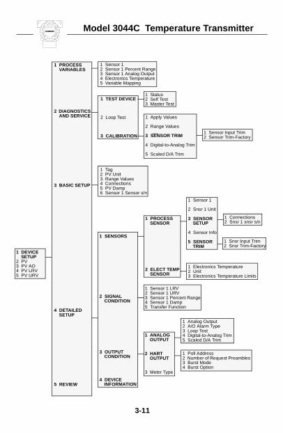
Model 3044C Temperature Transmitter
3-11
1 Sensor 12 Sensor 1 Percent Range3 Sensor 1 Analog Output4 Electronics Temperature5 Variable Mapping
1 Tag2 PV Unit3 Range Values4 Connections5 PV Damp6 Sensor 1 Sensor s/n
1 Status2 Self Test3 Master Test
1 Sensor 1 LRV2 Sensor 1 URV3 Sensor 1 Percent Range4 Sensor 1 Damp5 Transfer Function
1 Poll Address2 Number of Request Preambles3 Burst Mode4 Burst Option
1 Sensor Input Trim2 Sensor Trim-Factory
1 Analog Output2 A/O Alarm Type3 Loop Test4 Digital-to-Analog Trim5 Scaled D/A Trim
1 DEVICE SETUP
2 PV3 PV AO4 PV LRV5 PV URV
1 PROCESS VARIABLES
2 DIAGNOSTICS AND SERVICE
3 BASIC SETUP
4 DETAILED SETUP
5 REVIEW
1 TEST DEVICE
2 Loop Test
3 CALIBRATION
1 Apply Values
2 Range Values
3 SENSOR TRIM
4 Digital-to-Analog Trim
5 Scaled D/A Trim
1 SENSORS
2 SIGNAL CONDITION
3 OUTPUT CONDITION
4 DEVICE INFORMATION
1 Sensor 1
2 Snsr 1 Unit
3 SENSOR SETUP
4 Sensor Info
5 SENSOR TRIM
1 PROCESS SENSOR
2 ELECT TEMP SENSOR
1 Electronics Temperature2 Unit3 Electronics Temperature Limits
1 ANALOG OUTPUT
2 HART OUTPUT
3 Meter Type
1 Connections2 Snsr 1 snsr s/n
1 Snsr Input Trim2 Snsr Trim-Factory
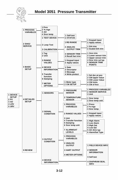
Model 3051 Pressure Transmitter
3-12
1 DEVICESETUP
2 PV3 AO4 LRV5 URV
1 PROCESSVARIABLES
2 DIAG/SERVICE
3 BASICSETUP
4 DETAILEDSETUP
5 REVIEW
1 Pres2 % rnge3 AO4 Snsr temp
1 TEST DEVICE
2 Loop Test
3 CALIBRATION
1 Tag2 Unit
3 RANGEVALUES
4 DEVICEINFORMATION
5 Transferfunction
6 Damping
7 METEROPTIONS
1 Self test2 STATUS
1 FIELD DEVICE INFO
2 SENSORINFORMATION
3 Self test
4 DIAPHRAM SEALINFO
1 RE-RANGE
2 ANALOGOUTPUT TRIM
3 SENSOR TRIM4 Recall fact trim
1 PRESSURESENSOR
2 TEMPERATURESENSOR
1 PROCESS VARIABLES2 SENSOR SERVICE3 Unit
1 Meter type2 CM SETUP
1 SENSORS
2 SIGNALCONDITION
3 OUTPUTCONDITION
4 DEVICEINFORMATION
1 Keypad input2 Apply values
1 Keypad input2 Apply values
1 Date2 Descriptor3 Message4 Write protect
1 D/A trim2 Scaled D/A trim
1 Snsr temp2 Snsr temp unit
1 Sel dec pt pos2 CM Upper Value3 CM Lower Value4 CM Units5 CM xf fnct
1 PROCESSVARIABLES
2 RANGE VALUES
3 Unit4 Transfer function5 Damping6 Snsr temp unit
7 ALARM/SATLEVELS
1 Press2 % rnge3 Snsr temp
1 Keypad input2 Apply values
1 High Alarm2 Low Alarm3 High Sat4 Low Sat5 AO Alrm typ6 Alarm/Sat Type
1 Zero trim2 Lower sensor trim3 Upper sensor trim4 Snsr trim cal typ5 SENSOR TRIM
POINTS
1 PROCESSVARIABLES
2 ANALOGOUTPUT
3 HART OUTPUT
4 METER OPTIONS
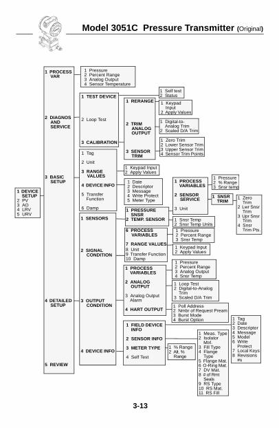
Model 3051C Pressure Transmitter (Original)
3-13
1 Tag
2 Unit
3 RANGEVALUES
4 DEVICE INFO
5 Transfer Function
6 Damp
1 Self test2 Status
1 Keypad Input
2 Apply Values
6 PROCESS VARIABLES
7 RANGE VALUES8 Unit9 Transfer Function 10 Damp
1 Loop Test2 Digital-to-Analog
Trim3 Scaled D/A Trim
1 Poll Address2 Nmbr of Request Pream3 Burst Mode4 Burst Option
1 Digital-to-Analog Trim
2 Scaled D/A Trim
1 Zero Trim2 Lower Sensor Trim3 Upper Sensor Trim4 Sensor Trim Points
1 Date2 Descriptor3 Message4 Write Protect5 Meter Type
1 Keypad Input2 Apply Values
1 Pressure2 Percent Range3 Snsr Temp
1 Keypad Input2 Apply Values
1 Pressure2 Percent Range3 Analog Output4 Snsr Temp
1 FIELD DEVICE INFO
2 SENSOR INFO
3 METER TYPE
4 Self Test
1 PROCESS VAR
2 DIAGNOS AND SERVICE
3 BASIC SETUP
4 DETAILED SETUP
5 REVIEW
1 TEST DEVICE
2 Loop Test
3 CALIBRATION
1 RERANGE
2 TRIM ANALOG OUTPUT
3 SENSOR TRIM
1 Pressure2 % Range3 Snsr temp
1 PROCESS VARIABLES
2 SENSOR SERVICE
3 Unit
1 SNSR TRIM
1 PROCESS VARIABLES
2 ANALOG OUTPUT
3 Analog Output Alarm
4 HART OUTPUT
1 Zero Trim
2 Lwr Snsr Trim
3 Upr Snsr Trim
4 Snsr Trim Pts.
1 PRESSURE SNSR
2 TEMP. SENSOR 1 Snsr Temp2 Snsr Temp Units
1 SENSORS
2 SIGNAL CONDITION
3 OUTPUT CONDITION
4 DEVICE INFO
1 Tag2 Date3 Descriptor4 Message5 Model6 Write
Protect7 Local Keys8 Revisions
#s
1 Meas. Type2 Isolator
Mtrl.3 Fill Type4 Flange
Type5 Flange Mat.6 O-Ring Mat.7 DV Mat.8 # of Rmt
Seals9 RS Type10 RS Mat.11 RS Fill
1 % Range2 Alt. %
Range
1 DEVICE SETUP
2 PV3 AO4 LRV5 URV
1 Pressure2 Percent Range3 Analog Output4 Sensor Temperature
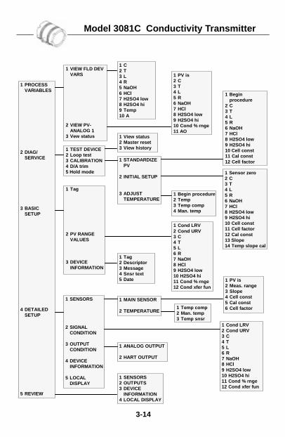
Model 3081C Conductivity Transmitter
3-14
1 VIEW FLD DEVVARS
2 VIEW PV-ANALOG 1
3 Vew status
1 C2 T3 L4 R5 NaOH6 HCl7 H2SO4 low8 H2SO4 hi9 Temp10 A
1 TEST DEVICE2 Loop test3 CALIBRATION4 D/A trim5 Hold mode
1 View status2 Master reset3 View history
1 MAIN SENSOR
2 TEMPERATURE
1 STANDARDIZEPV
2 INITIAL SETUP
3 ADJUSTTEMPERATURE
1 PROCESSVARIABLES
2 DIAG/SERVICE
3 BASICSETUP
4 DETAILEDSETUP
5 REVIEW
1 PV is2 C3 T4 L5 R6 NaOH7 HCl8 H2SO4 low9 H2SO4 hi10 Cond % rnge11 AO
1 Tag
2 PV RANGEVALUES
3 DEVICEINFORMATION
1 SENSORS
2 SIGNALCONDITION
3 OUTPUTCONDITION
4 DEVICEINFORMATION
5 LOCALDISPLAY
1 Begin procedure2 Temp3 Temp comp4 Man. temp
1 PV is2 Meas. range3 Slope4 Cell const5 Cal const6 Cell factor
1 Beginprocedure
2 C3 T4 L5 R6 NaOH7 HCl8 H2SO4 low9 H2SO4 hi10 Cell const11 Cal const12 Cell factor
1 Sensor zero2 C3 T4 L5 R6 NaOH7 HCl8 H2SO4 low9 H2SO4 hi10 Cell const11 Cell factor12 Cal const13 Slope14 Temp slope cal
1 Tag2 Descriptor3 Message4 Snsr text5 Date
1 ANALOG OUTPUT
2 HART OUTPUT
1 Temp comp2 Man. temp3 Temp snsr
1 Cond LRV2 Cond URV3 C4 T5 L6 R7 NaOH8 HCl9 H2SO4 low10 H2SO4 hi11 Cond % rnge12 Cond xfer fun
1 SENSORS2 OUTPUTS3 DEVICE
INFORMATION4 LOCAL DISPLAY
1 Cond LRV2 Cond URV3 C4 T5 L6 R7 NaOH8 HCl9 H2SO4 low10 H2SO4 hi11 Cond % rnge12 Cond xfer fun
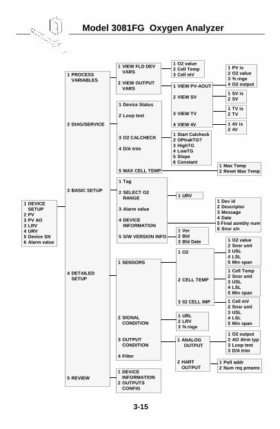
Model 3081FG Oxygen Analyzer
3-15
1 DEVICESETUP
2 PV3 PV AO3 LRV4 URV5 Device SN6 Alarm value
1 PROCESSVARIABLES
2 DIAG/SERVICE
3 BASIC SETUP
4 DETAILEDSETUP
5 REVIEW
1 VIEW PV-AOUT
2 VIEW SV
3 VIEW TV
4 VIEW 4V
1 O2 value2 Cell Temp3 Cell mV
1 VIEW FLD DEVVARS
2 VIEW OUTPUTVARS
1 SV is2 SV
1 Tag
2 SELECT O2RANGE
3 Alarm value
4 DEVICEINFORMATION
5 S/W VERSION INFO
1 Start Calcheck2 OPtrakTG?3 HighTG4 LowTG5 Slope6 Constant
1 PV is2 O2 value3 % rnge4 O2 output
1 Device Status
2 Loop test
3 O2 CALCHECK
4 D/A trim
5 MAX CELL TEMP
1 Dev id2 Descriptor3 Message4 Date5 Final asmbly num6 Snsr s/n
1 Max Temp2 Reset Max Temp
1 URV
1 Ver2 Bld3 Bld Date
1 O2 output2 AO Alrm typ3 Loop test3 D/A trim
1 O2 value2 Snsr unit3 USL4 LSL5 Min span
1 O2
2 CELL TEMP
3 02 CELL IMP
1 SENSORS
2 SIGNALCONDITION
3 OUTPUTCONDITION
4 Filter
1 DEVICEINFORMATION
2 OUTPUTSCONFIG
1 ANALOGOUTPUT
2 HARTOUTPUT
1 URL2 LRV3 % rnge
1 Poll addr2 Num req preams
1 Cell mV2 Snsr unit3 USL4 LSL5 Min span
1 Cell Temp2 Snsr unit3 USL4 LSL5 Min span
1 4V is2 4V
1 TV is2 TV
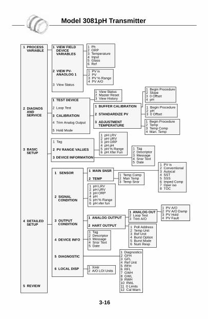
Model 3081pH Transmitter
3-16
1 Tag
2 PV RANGE VALUES
3 DEVICE INFORMATION
1 Poll Address2 Temp Unit3 Ref Unit4 Burst Option5 Burst Mode6 Num Resp
1 PROCESS VARIABLE
2 DIAGNOS AND SERVICE
3 BASIC SETUP
4 DETAILED SETUP
5 REVIEW
1 SENSOR
2 SIGNAL CONDITION
3 OUTPUT CONDITION
4 DEVICE INFO
5 DIAGNOSTIC
6 LOCAL DISP
1 ANALOG OUTPUT
2 HART OUTPUT
1 Ph2 ORP3 Temperature4 Input5 Glass6 Ref
1 VIEW FIELD DEVICE VARIABLES
2 VIEW PV-ANAOLOG 1
3 View Status
1 PV is2 PV3 PV % Range4 PV A/O
1 Begin Procedure2 Slope3 0 Offset4 pH1 TEST DEVICE
2 Loop Test
3 CALIBRATION
4 Trim Analog Output
5 Hold Mode
1 BUFFER CALIBRATION
2 STANDARDIZE PV
3 ADJUSTMENT TEMPERATURE
1 MAIN SNSR
2 TEMP
1 pH LRV2 pH URV3 pH ORP4 pH5 pH % Range6 pH xfer fun
1 ANALOG OUT2 Loop Test3 Trim A/O
1 Begin Procedure2 Temp3 Temp Comp4 Man. Temp
1 pH LRV2 pH URV3 pH ORP4 pH pH5 pH % Range6 pH Xfer Fun
1 Tag2 Descriptor3 Message4 Snsr Text5 Date
1 Tag2 Descriptor3 Message4 Snsr Text5 Date
1 View Status2 Master Reset3 View History
1 PV is2 Conventional3 Autocal4 SST5 SSS6 Imped Comp7 Oper iso8 TOC
1 Temp Comp2 Man Temp3 Temp Snsr
1 PV A/O2 PV A/O Damp3 PV Hold4 PV Fault
1 Diagnostics2 GFH3 GFL4 Ref Unit5 RFH6 RFL7 GWH8 GWL9 RWH10 RWL11 0 Limits12 Cal Warn
1 Xmtr 2 A/O LOI Units
1 Begin Procedure2 pH3 0 Offset
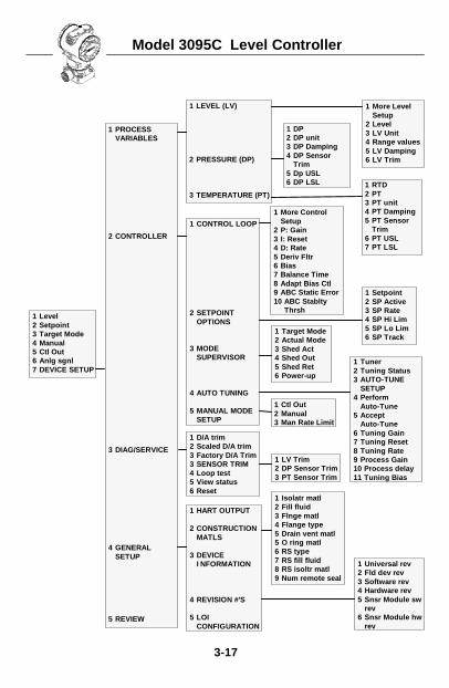
Model 3095C Level Controller
3-17
1 Level2 Setpoint3 Target Mode4 Manual5 Ctl Out6 Anlg sgnl7 DEVICE SETUP
1 LEVEL (LV)
2 PRESSURE (DP)
3 TEMPERATURE (PT)
1 More LevelSetup
2 Level3 LV Unit4 Range values5 LV Damping6 LV Trim
1 PROCESSVARIABLES
2 CONTROLLER
3 DIAG/SERVICE
4 GENERALSETUP
5 REVIEW
1 DP2 DP unit3 DP Damping4 DP Sensor
Trim5 Dp USL6 DP LSL
1 Target Mode2 Actual Mode3 Shed Act4 Shed Out5 Shed Ret6 Power-up
1 Setpoint2 SP Active3 SP Rate4 SP Hi Lim5 SP Lo Lim6 SP Track
1 More ControlSetup
2 P: Gain3 I: Reset4 D: Rate5 Deriv Fltr6 Bias7 Balance Time8 Adapt Bias Ctl9 ABC Static Error10 ABC Stablty
Thrsh
1 CONTROL LOOP
2 SETPOINTOPTIONS
3 MODESUPERVISOR
4 AUTO TUNING
5 MANUAL MODESETUP
1 RTD2 PT3 PT unit4 PT Damping5 PT Sensor
Trim6 PT USL7 PT LSL
1 Tuner2 Tuning Status3 AUTO-TUNE
SETUP4 Perform
Auto-Tune5 Accept
Auto-Tune6 Tuning Gain7 Tuning Reset8 Tuning Rate9 Process Gain10 Process delay11 Tuning Bias
1 LV Trim2 DP Sensor Trim3 PT Sensor Trim
1 Universal rev2 Fld dev rev3 Software rev4 Hardware rev5 Snsr Module sw
rev6 Snsr Module hw
rev
1 HART OUTPUT
2 CONSTRUCTIONMATLS
3 DEVICEI NFORMATION
4 REVISION #’S
5 LOICONFIGURATION
1 D/A trim2 Scaled D/A trim3 Factory D/A Trim3 SENSOR TRIM4 Loop test5 View status6 Reset
1 Ctl Out2 Manual3 Man Rate Limit
1 Isolatr matl2 Fill fluid3 Flnge matl4 Flange type5 Drain vent matl5 O ring matl6 RS type7 RS fill fluid8 RS isoltr matl9 Num remote seal
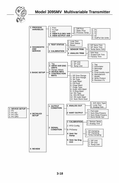
Model 3095MV Multivariable Transmitter
3-18
1 Pres2 % rnge3 A/O4 VIEW FLD DEV VAR5 VIEW OUTPUT VAR
1 Tag2 XMTR VAR ENG
UNITS3 Range Values4 DEVICE INFO5 CONTRUCTION
MATS
1 ANALOG OUT
2 HART OUTPUT
1 DP Damping2 SP Damping3 Temp Damping
1 DEVICE SETUP2 PV3 PV AO4 PV LRV5 PV URV
1 PROCESS VARIABLES
2 DIAGNOSTIC AND SERVICE
3 BASIC SETUP
4 DETAILED SETUP
5 REVIEW
1 TEST STATUS
2 CALIBRATION1 SENSOR TRIM
2 ANALOG TRIM
1 OUTPUT CONDITION
2 SIGNAL CONDITION
1 CALIBRATION
2 RTD Config
3 PVDamp
4 Xmtr Var Damp
5 Xmtr Var Eng Unit
1 Poll Addr2 Num Req Preams3 Num Resp Preams4 Burst Mode Opr
1 Loop Test2 View Status3 Reset 1 DP Sens Trim
2 SP Sens Trim3 Temp Sens Trim
1 Tag2 Descriptor3 Message4 Date5 Final Assbly num6 Manufacture7 Model8 Write Protect9 Revision #’s
1 Sensor Temp2 Analog Trim
1 Diff Pres2 Static Pres3 Process Temp
1 PV2 SV3 TV4 4V5 OutPut Var Units
1 D/A Trim2 Scaled D/A Trim3 Factory Trim
1 DP Unit2 SP Unit3 Temp Unit
1 A/O Alrm Type2 Loop Test3 Analog Trim
1 DP Unit2 SP Unit3 Temp Unit
1 DP Snsr Range2 SP Snsr Range3 SP Type4 Isoltr Matrl5 Fill Fluid6 Flnge Matrl7 Flnge Type8 Drain Vent Matrl9 O Ring Matrl10 RS Type11 RS Fill Fluid12 RS Isoltr Matrl13 Num Remt Seal
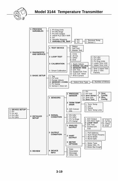
Model 3144 Temperature Transmitter
3-19
1 PV Eng Units2 PV $% Rnge3 PV A/O Output4 VIEW FLD DEV VAR5 SV6 Variable Mapping7 VARIABLE RE_MAP
1 Tag2 PV Unit3 Range Values4 SENSOR 1 CONN5 PV Damp6 Sensor 1 Snsr s/n
1 PROCESS SENSOR
2 TERM TEMP SNSR
3 A/D Conver Info
1 PV LRV2 PV URV3 PV % Rnge4 PV Damp
1 DEVICE SETUP2 PV3 PV AO4 PV LRV5 PV URV
1 PROCESS VARIABLES
2 DIAGNOSTIC AND SERVICE
3 BASIC SETUP
4 DETAILED SETUP
5 REVIEW
1 TEST DEVICE
2 LOOP TEST
3 CALIBRATION
4 Smart Calibration
1 Apply Values2 RANGE VALUES3 SENSOR TRIM4 D/A Trim5 Scaled D/A Trim6 CJC Cal. Value7 RTD Current
1 SENSORS
2 SIGNAL CONDITION
3 OUTPUT CONDITION
4 DEVICE INFO
1 ANALOG OUTPUT
2 HART OUTPUT
3 METER OPTIONS
1 Status2 Self Test3 Master Test
1 4 ma2 20 ma3 Other4 End
1 PV LRV2 PV URV3 PV Eng Units4 Lower Snsr Unit5 Upper Snsr Unit
1 Term Temp2 Unit3 Damp4 Term Temp Lmts
1 PV2 SV
1 Terminal Temp2 Sensor 1
1 PV2 PV Unit3 Snsr Setup4 Snsr Info5 Snsr Trim
1 A/O Output2 A/O Alrm Type3 LOOP TEST4 D/A Trim5 Scaled D/A
Trim
1 Snsr 1 Input Trim2 Snsr 1 Trim-
Factory
1 Select Snsr Type 1 Number of Wires
1 Snsr Config
2 Misc Config
1 Date2 Descriptor3 Message4 Other Info
1 Poll Address2 Num Reqst Preams3 Burst Mode4 Burst Opts
1 Meter Type2 Meter Dec. Pt.3 Meter Bar Graph
1 4 ma2 20 ma3 Other4 End
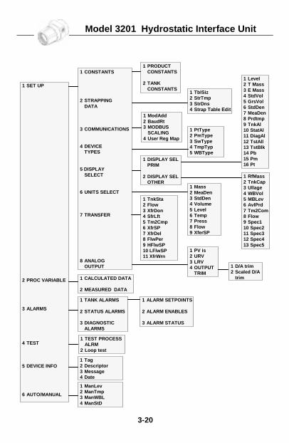
Model 3201 Hydrostatic Interface Unit
3-20
1 CONSTANTS
2 STRAPPINGDATA
3 COMMUNICATIONS
4 DEVICETYPES
5 DISPLAYSELECT
6 UNITS SELECT
7 TRANSFER
8 ANALOGOUTPUT
1 SET UP
2 PROC VARIABLE
3 ALARMS
4 TEST
5 DEVICE INFO
6 AUTO/MANUAL
1 PRODUCTCONSTANTS
2 TANKCONSTANTS
1 TblSiz2 StrTmp3 StrDns4 Strap Table Edit
1 ModAdd2 BaudRt3 MODBUS
SCALING4 User Reg Map
1 DISPLAY SELPRIM
2 DISPLAY SELOTHER
1 PtType2 PmType3 SwType4 TmpTyp5 WBType
1 TnkSta2 Flow3 XfrDon4 SfrLft5 Tm2Cmp6 XfrSP7 XfrDel8 FlwPer9 HFlwSP10 LFlwSP11 XfrWrn
1 Mass2 MeaDen3 StdDen4 Volume5 Level6 Temp7 Press8 Flow9 XferSP
1 PV is2 URV3 LRV4 OUTPUT
TRIM1 D/A trim2 Scaled D/A
trim
1 Level2 T Mass3 E Mass4 StdVol5 GrsVol6 StdDen7 MeaDen8 Prdtmp9 TnkAl10 StatAl11 DiagAl12 TstAll13 TstBlk14 Pb15 Pm16 Pt
1 TANK ALARMS
2 STATUS ALARMS
3 DIAGNOSTICALARMS
1 CALCULATED DATA
2 MEASURED DATA
1 ALARM SETPOINTS
2 ALARM ENABLES
3 ALARM STATUS
1 TEST PROCESSALRM
2 Loop test
1 ManLev2 ManTmp3 ManWBL4 ManStD
1 Tag2 Descriptor3 Message4 Date
1 RfMass2 TnkCap3 Ullage4 WBVol5 MBLev6 AvlPrd7 Tm2Com8 Flow9 Spec110 Spec211 Spec312 Spec413 Spec5
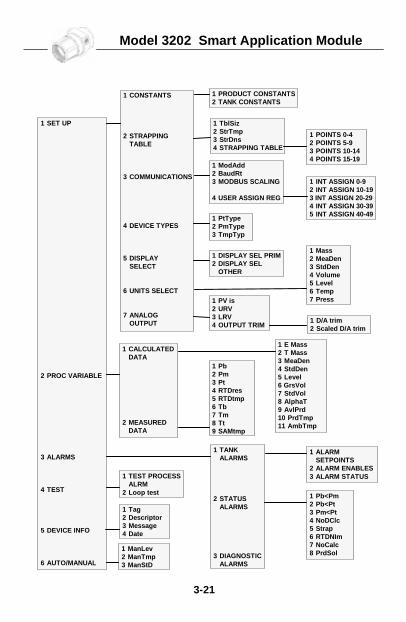
Model 3202 Smart Application Module
3-21
1 SET UP
2 PROC VARIABLE
3 ALARMS
4 TEST
5 DEVICE INFO
6 AUTO/MANUAL
1 CONSTANTS
2 STRAPPINGTABLE
3 COMMUNICATIONS
4 DEVICE TYPES
5 DISPLAYSELECT
6 UNITS SELECT
7 ANALOGOUTPUT
1 CALCULATEDDATA
2 MEASUREDDATA
1 TANKALARMS
2 STATUSALARMS
3 DIAGNOSTICALARMS
1 POINTS 0-42 POINTS 5-93 POINTS 10-144 POINTS 15-19
1 TEST PROCESSALRM
2 Loop test
1 PRODUCT CONSTANTS2 TANK CONSTANTS
1 TblSiz2 StrTmp3 StrDns4 STRAPPING TABLE
1 ModAdd2 BaudRt3 MODBUS SCALING
4 USER ASSIGN REG
1 INT ASSIGN 0-92 INT ASSIGN 10-193 INT ASSIGN 20-294 INT ASSIGN 30-395 INT ASSIGN 40-49
1 DISPLAY SEL PRIM2 DISPLAY SEL
OTHER
1 PtType2 PmType3 TmpTyp
1 PV is2 URV3 LRV4 OUTPUT TRIM
1 ALARMSETPOINTS
2 ALARM ENABLES3 ALARM STATUS
1 Mass2 MeaDen3 StdDen4 Volume5 Level6 Temp7 Press
1 Tag2 Descriptor3 Message4 Date
1 ManLev2 ManTmp3 ManStD
1 E Mass2 T Mass3 MeaDen4 StdDen5 Level6 GrsVol7 StdVol8 AlphaT9 AvlPrd10 PrdTmp11 AmbTmp
1 D/A trim2 Scaled D/A trim
1 Pb2 Pm3 Pt4 RTDres5 RTDtmp6 Tb7 Tm8 Tt9 SAMtmp
1 Pb<Pm2 Pb<Pt3 Pm<Pt4 NoDClc5 Strap6 RTDNIm7 NoCalc8 PrdSol
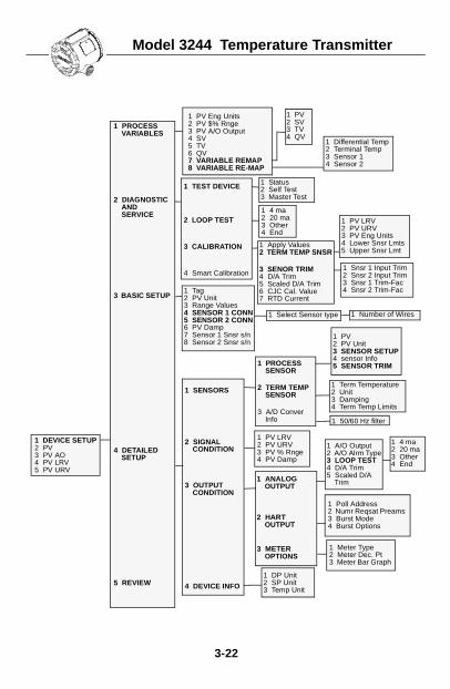
Model 3244 Temperature Transmitter
3-22
1 PROCESS SENSOR
2 TERM TEMP SENSOR
3 A/D Conver Info
1 Poll Address2 Numr Reqsat Preams3 Burst Mode4 Burst Options
1 DEVICE SETUP2 PV3 PV AO4 PV LRV5 PV URV
1 PROCESS VARIABLES
2 DIAGNOSTIC AND SERVICE
3 BASIC SETUP
4 DETAILED SETUP
5 REVIEW
1 SENSORS
2 SIGNAL CONDITION
3 OUTPUT CONDITION
4 DEVICE INFO
1 ANALOG OUTPUT
2 HART OUTPUT
3 METER OPTIONS
1 PV LRV2 PV URV3 PV % Rnge4 PV Damp
1 Status2 Self Test3 Master Test
1 4 ma2 20 ma3 Other4 End
1 A/O Output2 A/O Alrm Type3 LOOP TEST4 D/A Trim5 Scaled D/A
Trim
1 Term Temperature2 Unit3 Damping4 Term Temp Limits
1 PV2 SV3 TV4 QV
1 PV LRV2 PV URV3 PV Eng Units4 Lower Snsr Lmts5 Upper Snsr Lmt
1 DP Unit2 SP Unit3 Temp Unit
1 PV Eng Units2 PV $% Rnge3 PV A/O Output4 SV5 TV6 QV7 VARIABLE REMAP8 VARIABLE RE-MAP
1 Differential Temp2 Terminal Temp3 Sensor 14 Sensor 2
1 TEST DEVICE
2 LOOP TEST
3 CALIBRATION
4 Smart Calibration
1 Apply Values2 TERM TEMP SNSR
3 SENOR TRIM4 D/A Trim5 Scaled D/A Trim6 CJC Cal. Value7 RTD Current
1 Snsr 1 Input Trim2 Snsr 2 Input Trim3 Snsr 1 Trim-Fac4 Snsr 2 Trim-Fac1 Tag
2 PV Unit3 Range Values4 SENSOR 1 CONN5 SENSOR 2 CONN6 PV Damp7 Sensor 1 Snsr s/n8 Sensor 2 Snsr s/n
1 Select Sensor type 1 Number of Wires
1 4 ma2 20 ma3 Other4 End
1 Meter Type2 Meter Dec. Pt3 Meter Bar Graph
1 50/60 Hz filter
1 PV2 PV Unit3 SENSOR SETUP4 sensor Info5 SENSOR TRIM
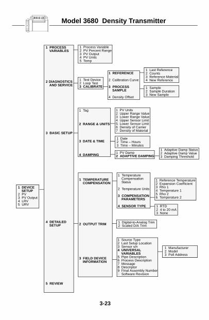
Model 3680 Density Transmitter
3-23
1 Process Variable2 PV Percent Range3 PV Output4 PV Units5 Temp
1 Tag
2 RANGE & UNITS
3 DATE & TIME
4 DAMPING
1 Last Reference2 Counts3 Reference Material4 New Reference
1 PV Units2 Upper Range Value3 Lower Range Value4 Upper Sensor Limit5 Lower Sensor Limit6 Density of Carrier7 Density of Material
1 PV Damp2 ADAPTIVE DAMPING
1 Digital-to-Analog Trim2 Scaled D/A Trim
1 Manufacturer2 Model3 Poll Address
1 DEVICE SETUP
2 PV3 PV Output4 LRV5 URV
1 PROCESS VARIABLES
2 DIAGNOSTICS AND SERVICE
3 BASIC SETUP
4 DETAILED SETUP
5 REVIEW
1 Test Device2 Loop Test3 CALIBRATE
1 REFERENCE
2 Calibration Curve
3 PROCESS SAMPLE
4 Density Offset
1 TEMPERATURE COMPENSATION
2 OUTPUT TRIM
3 FIELD DEVICE INFORMATION
1 RTD2 4 to 20 mA3 None
1 Temperature Compensation Status
2 Temperature Units
3 COMPENSATION PARAMETERS
4 SENSOR TYPE
1 Source Type2 Last Setup Location3 Sensor s/n4 UNIVERSAL
VARIABLES5 Pipe Description6 Process Description7 Message8 Descriptor9 Final Assembly Number1 Software Revision
1 Sample2 Sample Duration3 New Sample
1 Date2 Time – Hours3 Time – Minutes
1 Adaptive Damp Status2 Adaptive Damp Value3 Damping Threshold
1 Reference Temperature2 Expansion Coefficient3 Rho 14 Temperature 15 Rho 26 Temperature 2

Model 3809/3810 Variable Area Meter
3-24
1 DEVICESETUP
2 PV3 AO4 URV5 LRV
1 PROCESSVARIABLES
2 DIAGS &SERVICES
3 BASICSETUP
4 DETAILEDSETUP
1 PV2 % rnge
1 Tag2 Model3 Ser No4 CONFIGURATION
5 ANALOGOUTPUT
6 PULSE OUT
1 MEASUREMENTS
2 COMPUTATIONS
3 OUTPUTS
4 ALARMS
5 DEVICE INFO
1 ANALOG OUTPUT
2 CONTACT OUTPUT 1
3 CONTACT OUTPUT 2
4 PULSE OUT
5 HART OUTPUT
1 FLOW
2 TEMPERATURE3 DENSITY4 PRESSURE5 VISCOSITY
1 Unit2 Scaler3 Width
1 TOTALIZERS
1 Tag2 Descriptor3 Message4 Date5 Model6 Ser No7 Manufacturer8 Dev id9 REVISION INFO10 FLOW METER11 ACCESSORIES12 W & M
1 Cutoff2 CalFact
1 Alrm2 Reset Alarm3 STATUS4 ALARM
CONFIG
1 Alrm2 Reset alarm3 STATUS4 Seq no5 FltPos6 Int Temp7 TEST DEVICE
1 Loop Test2 Pulse O/P Test3 CONTACT O/PS4 Warning Level
1 AO2 % rnge3 URV4 LRV5 Damp6 AO Alrm typ
1 FlowRate Units2 CONFIGURATION3 METER
CALIBRATION
1 INVENTORY
2 RESETTABLE
1 Num req preams2 Poll addr
1 Alarm Status2 Diagnostic Status 1
1 AO2 % rnge3 URV4 LRV5 Damp6 AO Alrm typ
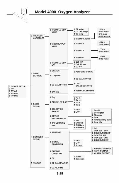
Model 4000 Oxygen Analyzer
3-25
1 VIEW FLD DEVVARS
2 VIEW OUTPUTVARS
3 VIEW FLD DEVMV
1 VIEW PV-AOUT
2 VIEW SV
3 VIEW TV
4 VIEW 4V
1 DEVICE SETUP2 PV3 PV AO4 PV LRV5 PV URV
1 PROCESSVARIABLES
2 DIAG/SERVICE
3 BASICSETUP
4 DETAILEDSETUP
5 REVIEW
1 O2 value2 O2 Cell temp3 CJ temp
1 Cell mV2 Cell TC mv3 CJ mV
1 PERFORM O2 CAL
2 O2 CAL STATUS
3 LASTCALCONSTANTS
4 Reset CalConstants
1 STATUS
2 Loop test
3 O2 CALIBRTION
4 D/A trim
1 SV is2 O2 value
1 PV is2 O2 value3 % rnge4 O2 output
1 4V is2 O2 value
1 TV is2 O2 value
1 Tag
2 ASSIGN PV & SV
3 SELECT O2RANGE
4 DEVICEINFORMATION
5 S/W VERSIONINFO
1 O22 O2 CELLTEMP3 COLDJUNCTEMP4 O2 CELL MV5 O2 CELLTCMV6 COLDJUNC MV
1 Dev id2 Descriptor3 Message4 Date5 Final asmbly num6 Snsr s/n
1 URV2 LRV
1 PV is2 SV is3 TV is4 4V is
1 Ver2 Chksum3 Bld Num4 Bld Date
1 SENSORS
2 SIGNALCONDITION
3 OUTPUTCONDTION
4 O2
5 O2 CALIBRATION
6 O2 ALARMS
1 ANALOG OUTPUT3 HART OUTPUT3 ALARM OUTPUT
1 URV2 LRV3 % rnge
1 Slope2 Constant
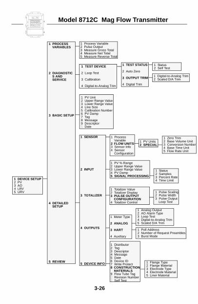
Model 8712C Mag Flow Transmitter
er
3-26
1 Process Variable2 Pulse Output3 Measure Gross Total4 Measure Net Total5 Measure Reverse Total
1 PV Unit2 Upper Range Value3 Lower Range Value4 Line Size5 Calibration Number6 PV Damp7 Tag8 Message9 Descriptor1 Date
1 TEST STATUS
2 Auto Zero
3 OUTPUT TRIM
4 Digital Trim
1 PV % Range2 Upper Range Value3 Lower Range Value4 PV Damp5 SIGNAL PROCESSING
1 Zero Trim2 Base Volume Unit3 Conversion Numb4 Base Time Unit5 Flow Rate Unit
1 Status2 Samples3 Percent Rate4 Time Limit
1 Distributor2 Tag3 Descriptor4 Message5 Date6 Device ID7 Write Protect8 CONSTRUCTION
MATERIALS9 Flow Tube Tag1 Revision Number2 Self Test
1 DEVICE SETUP2 PV3 AO4 LRV5 URV
1 PROCESS VARIABLES
2 DIAGNOSTICS AND SERVICE
3 BASIC SETUP
4 DETAILED SETUP
5 REVIEW
1 TEST DEVICE
2 Loop Test
3 Calibration
4 Digital-to-Analog Trim
1 SENSOR
2 INPUT
3 TOTALIZER
4 OUTPUTS
5 DEVICE INFO
1 Process Variable
2 FLOW UNITS3 Sensor Info4 Sensor
Configuration
1 PV Units2 SPECIAL
1 Status2 Self Test
1 Digital-to-Analog Trim2 Scaled D/A Trim
1 Totalizer Value2 Totalizer Display3 PULSE OUTPUT
CONFIGURATION4 Totalizer Control
1 Pulse Scaling2 Pulse Width3 Pulse Output
Loop Test
1 Meter Type
2 ANALOG
3 HART
4 Auxiliary
1 Poll Address2 Number of Request Preambles3 Burst Mode
1 Analog Output2 AO Alarm Type3 Loop Test4 Digital-to-Analog Trim5 Scaled D/A Trim
1 Flange Type2 Flange Material3 Electrode Type4 Electrode Material5 Liner Material
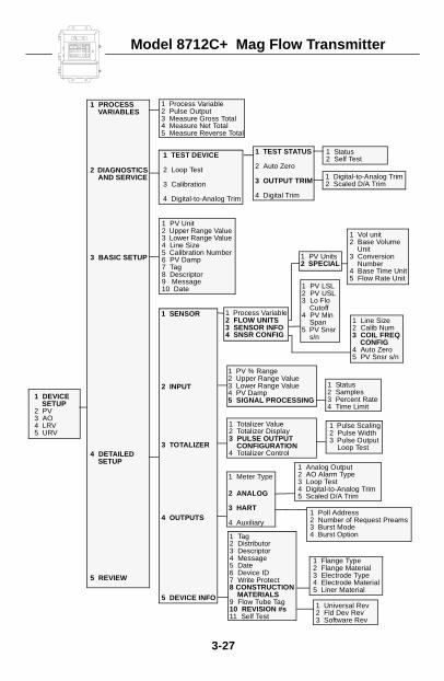
Model 8712C+ Mag Flow Transmitter
3-27
1 Process Variable2 Pulse Output3 Measure Gross Total4 Measure Net Total5 Measure Reverse Total
1 PV Unit2 Upper Range Value3 Lower Range Value4 Line Size5 Calibration Number6 PV Damp7 Tag8 Descriptor9 Message10 Date
1 TEST STATUS
2 Auto Zero
3 OUTPUT TRIM
4 Digital Trim
1 PV % Range2 Upper Range Value3 Lower Range Value4 PV Damp5 SIGNAL PROCESSING
1 Vol unit2 Base Volume
Unit3 Conversion
Number4 Base Time Unit5 Flow Rate Unit
1 Status2 Samples3 Percent Rate4 Time Limit
1 Tag 2 Distributor3 Descriptor4 Message5 Date6 Device ID7 Write Protect8 CONSTRUCTION
MATERIALS9 Flow Tube Tag10 REVISION #s11 Self Test
1 DEVICE SETUP
2 PV3 AO4 LRV5 URV
1 PROCESS VARIABLES
2 DIAGNOSTICS AND SERVICE
3 BASIC SETUP
4 DETAILED SETUP
5 REVIEW
1 TEST DEVICE
2 Loop Test
3 Calibration
4 Digital-to-Analog Trim
1 SENSOR
2 INPUT
3 TOTALIZER
4 OUTPUTS
5 DEVICE INFO
1 Process Variable2 FLOW UNITS3 SENSOR INFO4 SNSR CONFIG
1 PV Units2 SPECIAL
1 Status2 Self Test
1 Digital-to-Analog Trim2 Scaled D/A Trim
1 Totalizer Value2 Totalizer Display3 PULSE OUTPUT
CONFIGURATION4 Totalizer Control
1 Pulse Scaling2 Pulse Width3 Pulse Output
Loop Test
1 Meter Type
2 ANALOG
3 HART
4 Auxiliary1 Poll Address2 Number of Request Preams3 Burst Mode4 Burst Option
1 Analog Output2 AO Alarm Type3 Loop Test4 Digital-to-Analog Trim5 Scaled D/A Trim
1 Flange Type2 Flange Material3 Electrode Type4 Electrode Material5 Liner Material
1 PV LSL2 PV USL3 Lo Flo
Cutoff4 PV Min
Span5 PV Snsr
s/n
1 Line Size2 Calib Num3 COIL FREQ
CONFIG4 Auto Zero5 PV Snsr s/n
1 Universal Rev2 Fld Dev Rev3 Software Rev
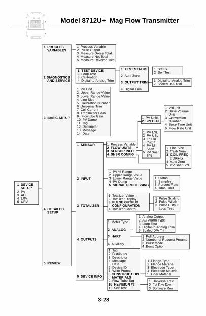
Model 8712U+ Mag Flow Transmitter
3-28
1 Process Variable2 Pulse Output3 Measure Gross Total4 Measure Net Total5 Measure Reverse Total
1 PV Unit2 Upper Range Value3 Lower Range Value4 Line Size5 Calibration Number6 Universal Trim7 Coil Current8 Transmitter Gain9 Flowtube Gain10 PV Damp11 Tag12 Descriptor13 Message14 Date
1 TEST STATUS
2 Auto Zero
3 OUTPUT TRIM
4 Digital Trim
1 PV % Range2 Upper Range Value3 Lower Range Value4 PV Damp5 SIGNAL PROCESSING
1 Vol unit2 Base Volume
Unit3 Conversion
Number4 Base Time Unit5 Flow Rate Unit
1 Status2 Samples3 Percent Rate4 Time Limit
1 Tag 2 Distributor3 Descriptor4 Message5 Date6 Device ID7 Write Protect8 CONSTRUCTION
MATERIALS9 Flow Tube Tag10 REVISION #s11 Self Test
1 DEVICE SETUP
2 PV3 AO4 LRV5 URV
1 PROCESS VARIABLES
2 DIAGNOSTICS AND SERVICE
3 BASIC SETUP
4 DETAILED SETUP
5 REVIEW
1 TEST DEVICE2 Loop Test3 Calibration4 Digital-to-Analog Trim
1 SENSOR
2 INPUT
3 TOTALIZER
4 OUTPUTS
5 DEVICE INFO
1 Process Variable2 FLOW UNITS3 SENSOR INFO4 SNSR CONFIG
1 PV Units2 SPECIAL
1 Status2 Self Test
1 Digital-to-Analog Trim2 Scaled D/A Trim
1 Totalizer Value2 Totalizer Display3 PULSE OUTPUT
CONFIGURATION4 Totalizer Control
1 Pulse Scaling2 Pulse Width3 Pulse Output
Loop Test
1 Meter Type
2 ANALOG
3 HART
4 Auxiliary
1 Poll Address2 Number of Request Preams3 Burst Mode4 Burst Option
1 Analog Output2 AO Alarm Type3 Loop Test4 Digital-to-Analog Trim5 Scaled D/A Trim
1 Flange Type2 Flange Material3 Electrode Type4 Electrode Material5 Liner Material
1 PV LSL2 PV USL3 Lo Flo
Cutoff4 PV Min
Span5 PV Snsr
S/N
1 Line Size2 Calib Num3 COIL FREQ
CONFIG4 Auto Zero5 PV Snsr S/N
1 Universal Rev2 Fld Dev Rev3 Software Rev
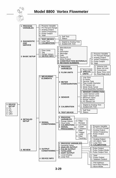
Model 8800 Vortex Flowmeter
3-29
1 Process Variable2 PV Percent Range3 Analog Output4 Vortex Frequency5 Pulse Output6 Total
1 Flow Units2 Tag3 Range Values4 DEVICE INFO
1 DEVICE SETUP
2 PV3 AO4 LRV5 URV
1 PROCESS VARIABLES
2 DIAGNOSTIC AND SERVICE
3 BASIC SETUP
4 DETAILED SETUP
5 REVIEW
1 TEST DEVICE2 Loop Test3 CALIBRATION
1 MEASURING ELEMENTS
2 SIGNAL CONDITIONING
3 OUTPUT CONDITIONING
4 DEVICE INFO
1 PROCESS VARIABLES
2 FLOW UNITS
3 METER CONFIGURATION
4 SENSOR
5 CALIBRATION
6 TEST DEVICE
1 Self Test2 Status
1 Digital-to-Analog Trim2 Scaled D/A Trim
1 Manufacturer2 Tag3 Descriptor4 Message5 Date6 Device ID7 Write Protect8 CONSTRUCTION MATERIALS9 REVISION NUMBERS
1 Process Variable2 PV Percent Range3 Analog Output4 Vortex Frequency5 Pulse Output6 Total
1 Flow Units2 SPECIAL
UNITS
1 Volume Unit2 Base Vol Unit3 Conversion4 Base Time Unit5 Flow Rate Unit
1 Line Size2 K-Factor3 Service Type4 Pipe Inside Diameter5 PV Sensor s/n6 Meter Body Serial7 Final Assembly Number
1 PROCESS VARIABLES2 Damping Value3 ANALOG OUTPUT4 PULSE OUTPUT5 TOTALIZER6 HART OUTPUT7 Local Display8 Loop Test
1 SENSOR CORRECTION2 Lower Sensor Limit3 Upper Sensor Limit4 Minimum Span5 Range Values6 PV Sensor s/n
1 Digital-to-Analog Trim2 Scaled D/A Trim
1 Self Test2 Status
1 Process Variable2 PV Percent Range3 Analog Output4 Vortex Frequency5 Pulse Output6 Total
1 Poll Address2 Num Req Preams3 Burst Mode
1 Total2 Pulse Output3 Totalizer Control
1 Pulse Output2 Pulse Output Mode3 Pulse Output Test
1 Analog Output2 AO Alarm Type3 Loop Test4 CALIBRATION
1 PROCESS VARIABLES
2 Range Values3 Flow Units4 CALIBRATION5 SIGNAL
PROCESSING
1 Filter Restore
2 Low Flow Cutoff
3 Lowpass Filter
4 Trigger Level
5 Filter Tracking
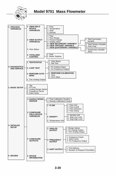
Model 9701 Mass Flowmeter
3-30
1 FLOW
2 DENSITY
3 Temperature Unit
1 Frequency Factor2 Rate Factor3 Fix Frequency Output
1 Poll Address2 Number of Request Preambles
1 Total2 Reset Totalizer
1 Tag2 PV Unit3 Analog Range Values4 Frequency Factor5 Rate Factor
1 Density Unit2 Slug Low Limit3 Slug High Limit
1 PROCESS VARIABLES
2 DIAGNOSTICS AND SERVICE
3 BASIC SETUP
4 DETAILED SETUP
5 REVIEW
1 CHARACTERIZE SENSOR
2 CONFIGURE FIELD DEVICE VARIABLES
3 CONFIGURE OUTPUTS
4 DEVICE INFORMATION
1 ANALOG OUTPUT
2 FREQUENCY OUTPUT
3 HART OUTPUT
1 Flow2 Temperature3 Total4 Density
1 VIEW FIELD DEVICE VARIABLES
2 VIEW OUTPUT VARIABLES
3 View Status
4 TOTALIZER CONTROL
1 Flow2 Flow Range3 Percent Range4 Analog Value5 VIEW SECONDARY VARIABLE6 VIEW TERTIARY VARIABLE7 VIEW QUATERNARY VARIABLE
1 Total Tertiary Variable 2 Pres Freq
1 Quaternary Variable Dens
1 Total Secondary Variable
1 TEST/STATUS
2 LOOP TEST
3 PERFOMR AUTO ZERO
4 Trim Analog Output
1 View Status2 Self Test
1 Fix Analog Output2 Fix Frequency Output
1 PERFORM CALIBRATION2 Flow3 Zero Value
1 Flow Calibration Number2 Density Calibration Factor
1 Flow Unit2 Flow Cutoff3 Flow Direction4 Flow Damp
1 Range Values2 Fix Analog Output3 Trim Analog Output
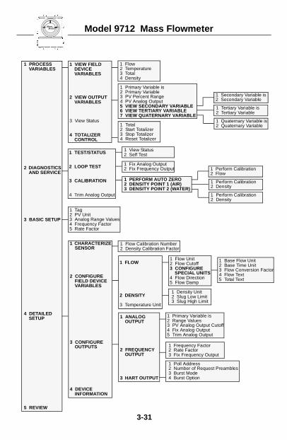
Micro Motion
Model 9712 Mass Flowmeter3-31
1 FLOW
2 DENSITY
3 Temperature Unit
1 Frequency Factor2 Rate Factor3 Fix Frequency Output
1 Poll Address2 Number of Request Preambles3 Burst Mode4 Burst Option
1 Total2 Start Totalizer3 Stop Totalizer4 Reset Totalizer
1 Tag2 PV Unit3 Analog Range Values4 Frequency Factor5 Rate Factor
1 Density Unit2 Slug Low Limit3 Slug High Limit
1 PROCESS VARIABLES
2 DIAGNOSTICS AND SERVICE
3 BASIC SETUP
4 DETAILED SETUP
5 REVIEW
1 CHARACTERIZE SENSOR
2 CONFIGURE FIELD DEVICE VARIABLES
3 CONFIGURE OUTPUTS
4 DEVICE INFORMATION
1 ANALOG OUTPUT
2 FREQUENCY OUTPUT
3 HART OUTPUT
1 Flow2 Temperature3 Total4 Density
1 VIEW FIELD DEVICE VARIABLES
2 VIEW OUTPUT VARIABLES
3 View Status
4 TOTALIZER CONTROL
1 Primary Variable is2 Primary Variable3 PV Percent Range4 PV Analog Output5 VIEW SECONDARY VARIABLE6 VIEW TERTIARY VARIABLE7 VIEW QUATERNARY VARIABLE
1 Tertiary Variable is2 Tertiary Variable
1 Quaternary Variable is2 Quaternary Variable
1 Secondary Variable is2 Secondary Variable
1 Perform Calibration2 Density
1 Perform Calibration2 Density
1 Perform Calibration2 Flow
1 TEST/STATUS
2 LOOP TEST
3 CALIBRATION
4 Trim Analog Output
1 View Status2 Self Test
1 Fix Analog Output2 Fix Frequency Output
1 PERFORM AUTO ZERO2 DENSITY POINT 1 (AIR)3 DENSITY POINT 2 (WATER)
1 Flow Calibration Number2 Density Calibration Factor
1 Flow Unit2 Flow Cutoff3 CONFIGURE
SPECIAL UNITS4 Flow Direction5 Flow Damp
1 Base Flow Unit2 Base Time Unit3 Flow Conversion Factor4 Flow Text5 Total Text
1 Primary Variable is2 Range Values3 PV Analog Output Cutoff4 Fix Analog Output5 Trim Analog Output
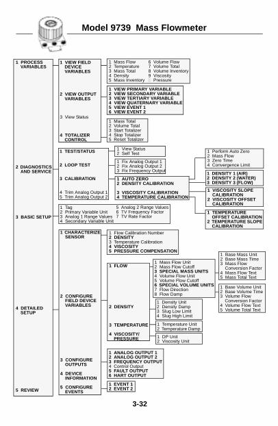
Model 9739 Mass Flowmeter
3-32
1 FLOW
2 DENSITY
3 TEMPERATURE
4 VISCOSITY/PRESSURE
1 Mass Total2 Volume Total3 Start Totalizer4 Stop Totalizer5 Reset Totalizer
1 Tag2 Primary Variable Unit3 Analog 1 Range Values4 Secondary Variable Unit
1 DP Unit2 Viscosity Unit
1 PROCESS VARIABLES
2 DIAGNOSTICS AND SERVICE
3 BASIC SETUP
4 DETAILED SETUP
5 REVIEW
1 CHARACTERIZE SENSOR
2 CONFIGURE FIELD DEVICE VARIABLES
3 CONFIGURE OUTPUTS
4 DEVICE INFORMATION
5 CONFIGURE EVENTS
1 ANALOG OUTPUT 12 ANALOG OUTPUT 2 3 FREQUENCY OUTPUT4 Control Output5 FAULT OUTPUT6 HART OUTPUT
1 Mass Flow2 Temperature3 Mass Total4 Density5 Mass Inventory
1 VIEW FIELD DEVICE VARIABLES
2 VIEW OUTPUT VARIABLES
3 View Status
4 TOTALIZER CONTROL
1 VIEW PRIMARY VARIABLE2 VIEW SECONDARY VARIABLE3 VIEW TERTIARY VARIABLE4 VIEW QUATERNARY VARIABLE5 VIEW EVENT 16 VIEW EVENT 2
1 DENSITY 1 (AIR)2 DENSITY 2 (WATER)3 DENSITY 3 (FLOW)
1 Perform Auto Zero2 Mass Flow3 Zero Time4 Convergence Limit
1 TEST/STATUS
2 LOOP TEST
3 CALIBRATION
4 Trim Analog Output 15 Trim Analog Output 2
1 View Status2 Self Test
1 Fix Analog Output 12 Fix Analog Output 23 Fix Frequency Output
1 AUTO ZERO2 DENSITY CALIBRATION
3 VISCOSITY CALIBRATION4 TEMPERATURE CALIBRATION
1 Flow Calibration Number2 DENSITY3 Temperature Calibration4 VISCOSITY5 PRESSURE COMPENSATION
1 Mass Flow Unit2 Mass Flow Cutoff3 SPECIAL MASS UNITS4 Volume Flow Unit5 Volume Flow Cutoff6 SPECIAL VOLUME UNITS7 Flow Direction8 Flow Damp
1 Base Mass Unit2 Base Mass Time3 Mass Flow
Conversion Factor4 Mass Flow Text5 Mass Total Text
6 Volume Flow7 Volume Total8 Volume Inventory9 Viscosity1 Pressure
1 VISCOSITY SLOPE CALIBRATION
2 VISCOSITY OFFSET CALIBRATION
1 TEMPERATURE OFFSET CALIBRATION
2 TEMPERATURE SLOPE CALIBRATION
5 Analog 2 Range Values6 TV Frequency Factor7 TV Rate Factor
1 EVENT 12 EVENT 2
1 Base Volume Unit2 Base Volume Time3 Volume Flow
Conversion Factor4 Volume Flow Text5 Volume Total Text
1 Temperature Unit2 Temperature Damp
1 Density Unit2 Density Damp3 Slug Low Limit4 Slug High Limit
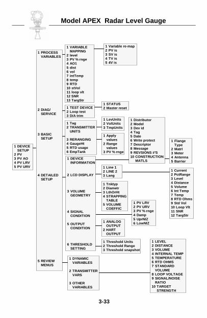
Model APEX Radar Level Gauge
3-33
1 DEVICESETUP
2 PV3 PV AO4 PV LRV5 PV URV
1 PROCESSVARIABLES
2 DIAG/SERVICE
3 BASICSETUP
4 DETAILEDSETUP
5 REVIEWMENUS
1 VARIABLEMAPPING
2 level3 PV % rnge4 AO15 dist6 vol7 intTemp8 temp9 RTD10 stVol11 loop vlt12 SNR13 TargStr
1 Variable re-map2 PV is3 SV is4 TV is5 4V is
1 TEST DEVICE2 Loop test3 D/A trim
1 STATUS2 Master reset
1 Tag2 TRANSMITTER
UNITS
3 RERANGING4 GaugeHt5 RTD usage6 EmpTank
1 DEVICEINFORMATION
2 LCD DISPLAY
3 VOLUMEGEOMETRY
4 SIGNALCONDITION
5 OUTPUTCONDITION
6 THRESHOLDSETTING
1 DYNAMICVARIABLES
2 TRANSMITTERVARS
3 OTHERVARIABLES
1 LevUnits2 VolUnits3 TmpUnits
1 Applyvalues
2 Rangevalues
3 PV % rnge
1 Distributor2 Model3 Dev id4 Tag5 Date6 Write protect7 Descriptor8 Message9 REVSIONS #’S10 CONSTRUCTION
MATLS
1 FlangeType
2 Matrl3 Meter4 Antenna5 Barrier
1 Line 12 LINE 23 Lang
1 Tnktyp2 Diametr3 LthOrHt4 STRAPPING
TABLE5 VOLUME
COEFFIC
1 PV LRV2 PV URV3 PV % rnge4 Damp5 UprNlZ6 LowNlZ1 ANALOG
OUTPUT2 HART
OUTPUT
1 Threshold Units2 Threshold Range3 Threshold snapshot
1 Current2 PctRange3 Level4 Distance5 Volume6 Int Temp7 Temp8 RTD Ohms9 Std Vol10 Loop Vlt11 SNR12 TargStr
1 LEVEL2 DISTANCE3 VOLUME4 INTERNAL TEMP5 TEMPERATURE6 RTD OHMS7 STANDARD
VOLUME8 LOOP VOLTAGE9 SIGNAL/NOISE
RATIO10 TARGET
STRENGTH
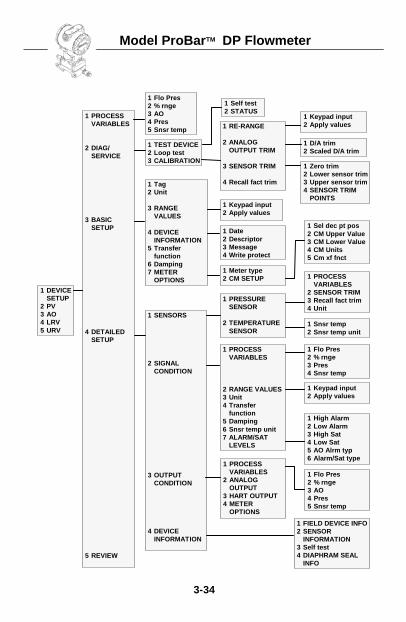
Model ProBarTM DP Flowmeter
3-34
1 Flo Pres2 % rnge3 AO4 Pres5 Snsr temp
1 Flo Pres2 % rnge3 AO4 Pres5 Snsr temp
1 Snsr temp2 Snsr temp unit
1 TEST DEVICE2 Loop test3 CALIBRATION
1 RE-RANGE
2 ANALOGOUTPUT TRIM
3 SENSOR TRIM
4 Recall fact trim
1 Self test2 STATUS
1 D/A trim2 Scaled D/A trim
1 Keypad input2 Apply values
1 Zero trim2 Lower sensor trim3 Upper sensor trim4 SENSOR TRIM
POINTS
1 DEVICESETUP
2 PV3 AO4 LRV5 URV
1 PROCESSVARIABLES
2 DIAG/SERVICE
3 BASICSETUP
4 DETAILEDSETUP
5 REVIEW
1 PRESSURESENSOR
2 TEMPERATURESENSOR
1 Sel dec pt pos2 CM Upper Value3 CM Lower Value4 CM Units5 Cm xf fnct
1 Meter type2 CM SETUP
1 Date2 Descriptor3 Message4 Write protect
1 Keypad input2 Apply values
1 Tag2 Unit
3 RANGEVALUES
4 DEVICEINFORMATION
5 Transferfunction
6 Damping7 METER
OPTIONS
1 SENSORS
2 SIGNALCONDITION
3 OUTPUTCONDITION
4 DEVICEINFORMATION
1 PROCESSVARIABLES
2 SENSOR TRIM3 Recall fact trim4 Unit
1 PROCESSVARIABLES
2 ANALOGOUTPUT
3 HART OUTPUT4 METER
OPTIONS
1 FIELD DEVICE INFO2 SENSOR
INFORMATION3 Self test4 DIAPHRAM SEAL
INFO
1 High Alarm2 Low Alarm3 High Sat4 Low Sat5 AO Alrm typ6 Alarm/Sat type
1 PROCESSVARIABLES
2 RANGE VALUES3 Unit4 Transfer
function5 Damping6 Snsr temp unit7 ALARM/SAT
LEVELS
1 Flo Pres2 % rnge3 Pres4 Snsr temp
1 Keypad input2 Apply values
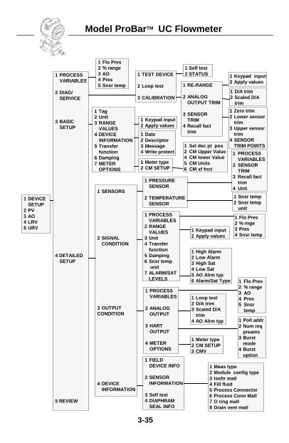
Model ProBarTM UC Flowmeter
3-35
1 DEVICESETUP
2 PV3 AO4 LRV5 URV
1 PROCESSVARIABLES
2 DIAG/SERVICE
3 BASICSETUP
4 DETAILEDSETUP
5 REVIEW
1 Flo Pres2 % range3 AO4 Pres5 Snsr temp
1 TEST DEVICE
2 Loop test
3 CALIBRATION
1 Tag2 Unit3 RANGE
VALUES4 DEVICE
INFORMATION5 Transfer
function6 Damping7 METER
OPTIONS
1 SENSORS
2 SIGNALCONDITION
3 OUTPUTCONDITION
4 DEVICEINFORMATION
1 Self test2 STATUS
1 RE-RANGE
2 ANALOGOUTPUT TRIM
3 SENSORTRIM
4 Recall facttrim
1 PROCESSVARIABLES
2 ANALOGOUTPUT
3 HARTOUTPUT
4 METEROPTIONS
1 Date2 Descriptor3 Message4 Write protect
1 Keypad input2 Apply values
1 PROCESSVARIABLES
2 RANGEVALUES
3 Unit4 Transfer
function5 Damping6 Snsr temp
unit7 ALARM/SAT
LEVELS
1 Meter type2 CM SETUP
1 FIELDDEVICE INFO
2 SENSORINFORMATION
3 Self test4 DIAPHRAM
SEAL INFO
1 D/A trim2 Scaled D/A
trim
1 Keypad input2 Apply values
1 Zero trim2 Lower sensor
trim3 Upper sensor
trim4 SENSOR
TRIM POINTS
1 Keypad input2 Apply values
1 Poll addr2 Num req
preams3 Burst
mode4 Burst
option
1 High Alarm2 Low Alarm3 High Sat4 Low Sat5 AO Alrm typ6 Alarm/Sat Type 1 Flo Pres
2 % range3 AO4 Pres5 Snsr
temp
1 Meter type2 CM SETUP3 CMV
1 PRESSURESENSOR
2 TEMPERATURESENSOR
1 PROCESSVARIABLES
2 SENSORTRIM
3 Recall facttrim
4 Unit
1 Sel dec pt pos2 CM Upper Value4 CM lower Value5 CM Units6 CM xf fnct
1 Snsr temp2 Snsr temp
unit
1 Meas type2 Module config type3 Isoltr matl4 Fill fluid5 Process Connector6 Process Conn Matl7 O ring matl8 Drain vent matl
1 Loop test2 D/A trim3 Scaled D/A
trim4 AO Alrm typ
1 Flo Pres2 % rnge3 Pres4 Snsr temp
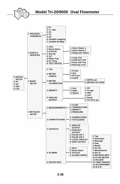
Model Tri-20/9000 Oval Flowmeter
3-36
1 DEVICESETUP
2 PV3 AO4 URV5 LRV
1 PROCESSVARIABLES
2 DIAGS &SERVICES
3 BASICSETUP
4 DETAILEDSETUP
1 PV2 % rnge3 SV4 TV5 QV6 Variable mapping7 Variable Re-Map
1 Alrm2 Reset Alarm3 STATUS4 Seq No5 Vcf6 Meter Freq8 Int Temp9 TEST DEVICE
1 ANALOGOUTPUT
2 CONTACTOUTPUT
3 PULSE O/P 14 PULSE O/P 25 LOCAL DISPLAY6 HART OUTPUT
1 Loop Test2 CONTACT O/P3 Pulse O/P Test4 Warning Level
1 MFFR unit2 METER FACTORS
1 Alarm Status 12 Alarm Status 23 Diagnostic Status
1 K-Fact2 Unit3 I/P Func4 Cutoff
1 Alrm:2 Reset Alarm3 STATUS4 ALARM CONFIG
1 Tag
2 METERCONFIG
3 METERCALIBRATION
4 DENSITY
5 ANALOGOUTPUT
1 AO2 % rnge3 URV4 LRV5 Damp6 AO Alrm typ
1 Tag2 Descriptor3 Message4 Date5 Model6 Ser No7 Manufacturer8 Dev id9 REVISION INFO10 FLOW METER11 PULSER12 TEMP SENSOR13 ACCESSORIES14 W & M
1 Unit2 Refer3 Obsvd
1 MEASUREMENTS
2 COMPUTATIONS
3 OUTPUTS
4 ALARMS
5 DEVICE INFO
1 FLOW2 TEMPERATURE3 DENSITY4 PRESSURE
1 CORRECTIONS2 TOTALIZERS
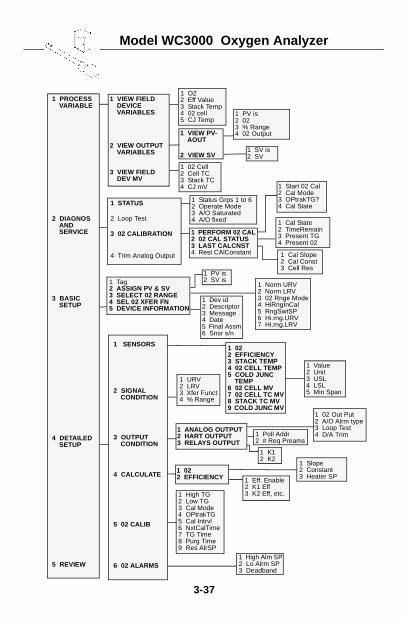
Model WC3000 Oxygen Analyzer
3-37
1 Tag2 ASSIGN PV & SV3 SELECT 02 RANGE4 SEL 02 XFER FN5 DEVICE INFORMATION
1 Poll Addr2 # Req Preams
1 PROCESS VARIABLE
2 DIAGNOS AND SERVICE
3 BASIC SETUP
4 DETAILED SETUP
5 REVIEW
1 SENSORS
2 SIGNAL CONDITION
3 OUTPUT CONDITION
4 CALCULATE
5 02 CALIB
6 02 ALARMS
1 ANALOG OUTPUT2 HART OUTPUT3 RELAYS OUTPUT
1 O22 Eff Value3 Stack Temp4 02 cell5 CJ Temp
1 VIEW FIELD DEVICE VARIABLES
2 VIEW OUTPUT VARIABLES
3 VIEW FIELD DEV MV
1 VIEW PV-AOUT
2 VIEW SV
1 Start 02 Cal2 Cal Mode3 OPtrakTG?4 Cal State1 STATUS
2 Loop Test
3 02 CALIBRATION
4 Trim Analog Output
1 Status Grps 1 to 62 Operate Mode 3 A/O Saturated4 A/O fixed
1 022 EFFICIENCY3 STACK TEMP4 02 CELL TEMP5 COLD JUNC
TEMP6 02 CELL MV7 02 CELL TC MV8 STACK TC MV9 COLD JUNC MV
1 URV2 LRV3 Xfer Funct4 % Range
1 02 Out Put2 A/O Alrm type3 Loop Test4 D/A Trim
1 Cal Slope2 Cal Const3 Cell Res
1 PV is2 SV is
1 Norm URV2 Norm LRV3 02 Rnge Mode4 HiRngInCal5 RngSwtSP6 Hi.rng.URV7 Hi.rng.LRV
1 022 EFFICIENCY
1 02 Cell2 Cell TC3 Stack TC4 CJ mV
1 PV is2 023 % Range4 02 Output
1 SV is2 SV
1 PERFORM 02 CAL2 02 CAL STATUS3 LAST CALCNST4 Rest CAlConstant
1 Cal State2 TimeRemain3 Present TG4 Present 02
1 Dev id2 Descriptor3 Message4 Date5 Final Assm6 Snsr s/n
1 Value2 Unit3 USL4 LSL5 Min Span
1 Eff. Enable2 K1 Eff3 K2 Eff, etc.
1 K12 K2
1 Slope2 Constant3 Heater SP
1 High TG2 Low TG3 Cal Mode4 OPtrakTG5 Cal Intrvl6 NxtCalTime7 TG Time8 Purg Time9 Res AlrSP
1 High Alm SP2 Lo Alrm SP3 Deadband

3-38
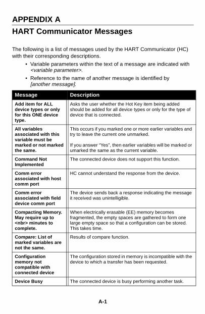
APPENDIX A
HART Communicator Messages
The following is a list of messages used by the HART Communicator (HC) with their corresponding descriptions.
• Variable parameters within the text of a message are indicated with <variable parameter>.
• Reference to the name of another message is identified by [another message].
Message Description
Add item for ALL device types or only for this ONE device type.
Asks the user whether the Hot Key item being added should be added for all device types or only for the type of device that is connected.
All variables associated with this variable must be marked or not marked the same.
This occurs if you marked one or more earlier variables and try to leave the current one unmarked.
If you answer “Yes”, then earlier variables will be marked or umarked the same as the current variable.
Command Not Implemented
The connected device does not support this function.
Comm error associated with host comm port
HC cannot understand the response from the device.
Comm error associated with field device comm port
The device sends back a response indicating the message it received was unintelligible.
Compacting Memory. May require up to <nbr> minutes to complete.
When electrically erasable (EE) memory becomes fragmented, the empty spaces are gathered to form one large empty space so that a configuration can be stored. This takes time.
Compare: List of marked variables are not the same.
Results of compare function.
Configuration memory not compatible with connected device
The configuration stored in memory is incompatible with the device to which a transfer has been requested.
Device Busy The connected device is busy performing another task.
A-1
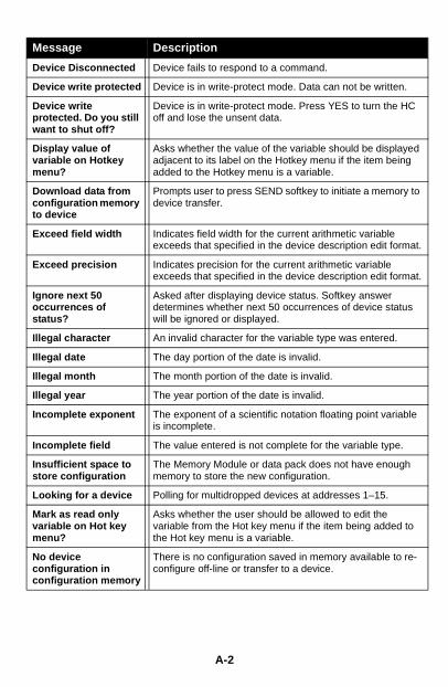
Message Description
Device Disconnected Device fails to respond to a command.
Device write protected Device is in write-protect mode. Data can not be written.
Device write protected. Do you still want to shut off?
Device is in write-protect mode. Press YES to turn the HC off and lose the unsent data.
Display value of variable on Hotkey menu?
Asks whether the value of the variable should be displayed adjacent to its label on the Hotkey menu if the item being added to the Hotkey menu is a variable.
Download data from configuration memory to device
Prompts user to press SEND softkey to initiate a memory to device transfer.
Exceed field width Indicates field width for the current arithmetic variable exceeds that specified in the device description edit format.
Exceed precision Indicates precision for the current arithmetic variable exceeds that specified in the device description edit format.
Ignore next 50 occurrences of status?
Asked after displaying device status. Softkey answer determines whether next 50 occurrences of device status will be ignored or displayed.
Illegal character An invalid character for the variable type was entered.
Illegal date The day portion of the date is invalid.
Illegal month The month portion of the date is invalid.
Illegal year The year portion of the date is invalid.
Incomplete exponent The exponent of a scientific notation floating point variable is incomplete.
Incomplete field The value entered is not complete for the variable type.
Insufficient space to store configuration
The Memory Module or data pack does not have enough memory to store the new configuration.
Looking for a device Polling for multidropped devices at addresses 1–15.
Mark as read only variable on Hot key menu?
Asks whether the user should be allowed to edit the variable from the Hot key menu if the item being added to the Hot key menu is a variable.
No device configuration in configuration memory
There is no configuration saved in memory available to re-configure off-line or transfer to a device.
A-2
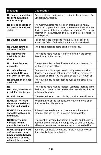
Message Description
No device description for configuration in offline storage
Due to a stored configuration created in the presence of a DD not now available.
No device description for device at address <nbr>.
The Communicator has not been programmed with a device description that it can use to communicate with the device it found at the indicated polling address. The device information (manufacturer ID, device ID, device revision) is also displayed.
No Device Found Poll of address zero fails to find a device, or poll of all addresses fails to find a device if auto-poll is enabled.
No Device found at address 0. Poll?
The polling option is set to ask before polling.
No Hotkey menu available for this device.
There is no menu named “Hotkey” defined in the device description for this device.
No offline devices available.
There are no device descriptions available to be used to configure a device offline.
No online device connected. Do you still want to turn off?
Communicator is set up to send configuration to online device. The device is not connected and you pressed off key before sending. You are being asked if OK to turn off.
No simulation devices available.
There are no device descriptions available to simulate a device.
No UPLOAD_VARIABLES in ddl for this device
There is no menu named “upload_variables” defined in the device description for this device. This menu is required for offline configuration.
No Valid Items The selected menu or edit display contains no valid items.
NOTICE: There are dependent variables for this unit variable.
When marking offline variables, there are other variables that depend on this variable.
NOTICE: Unit relation variables will also be unmarked.
If the unit variable is marked then unmark the relation variable. The unit will be unmarked automatically.
NOTICE: The unit variable for this variable is unmarked.
The variable is marked as part of a relation and the unit is not yet marked. That is, the range may be sent to a device with units that are not the same as what is stored offline.
NOTICE: Upgrade 275 software to access new connected device functions. Continue with old description?
You have connected to a device that is a newer revision than what is linked into the HC.
A-3
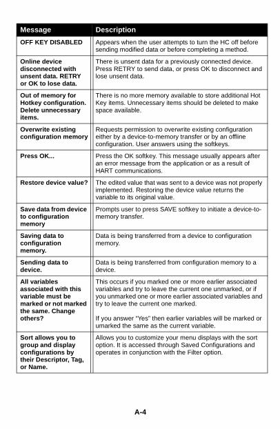
Message Description
OFF KEY DISABLED Appears when the user attempts to turn the HC off before sending modified data or before completing a method.
Online device disconnected with unsent data. RETRY or OK to lose data.
There is unsent data for a previously connected device. Press RETRY to send data, or press OK to disconnect and lose unsent data.
Out of memory for Hotkey configuration. Delete unnecessary items.
There is no more memory available to store additional Hot Key items. Unnecessary items should be deleted to make space available.
Overwrite existing configuration memory
Requests permission to overwrite existing configuration either by a device-to-memory transfer or by an offline configuration. User answers using the softkeys.
Press OK... Press the OK softkey. This message usually appears after an error message from the application or as a result of HART communications.
Restore device value? The edited value that was sent to a device was not properly implemented. Restoring the device value returns the variable to its original value.
Save data from device to configuration memory
Prompts user to press SAVE softkey to initiate a device-to-memory transfer.
Saving data to configuration memory.
Data is being transferred from a device to configuration memory.
Sending data to device.
Data is being transferred from configuration memory to a device.
All variables associated with this variable must be marked or not marked the same. Change others?
This occurs if you marked one or more earlier associated variables and try to leave the current one unmarked, or if you unmarked one or more earlier associated variables and try to leave the current one marked.
If you answer “Yes” then earlier variables will be marked or umarked the same as the current variable.
Sort allows you to group and display configurations by their Descriptor, Tag, or Name.
Allows you to customize your menu displays with the sort option. It is accessed through Saved Configurations and operates in conjunction with the Filter option.
A-4
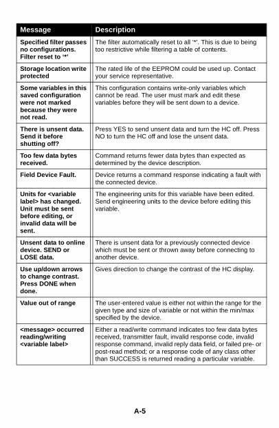
Message Description
Specified filter passes no configurations. Filter reset to ‘*’
The filter automatically reset to all ‘*’. This is due to being too restrictive while filtering a table of contents.
Storage location write protected
The rated life of the EEPROM could be used up. Contact your service representative.
Some variables in this saved configuration were not marked because they were not read.
This configuration contains write-only variables which cannot be read. The user must mark and edit these variables before they will be sent down to a device.
There is unsent data. Send it before shutting off?
Press YES to send unsent data and turn the HC off. Press NO to turn the HC off and lose the unsent data.
Too few data bytes received.
Command returns fewer data bytes than expected as determined by the device description.
Field Device Fault. Device returns a command response indicating a fault with the connected device.
Units for <variable label> has changed. Unit must be sent before editing, or invalid data will be sent.
The engineering units for this variable have been edited. Send engineering units to the device before editing this variable.
Unsent data to online device. SEND or LOSE data.
There is unsent data for a previously connected device which must be sent or thrown away before connecting to another device.
Use up/down arrows to change contrast. Press DONE when done.
Gives direction to change the contrast of the HC display.
Value out of range The user-entered value is either not within the range for the given type and size of variable or not within the min/max specified by the device.
<message> occurred reading/writing <variable label>
Either a read/write command indicates too few data bytes received, transmitter fault, invalid response code, invalid response command, invalid reply data field, or failed pre- or post-read method; or a response code of any class other than SUCCESS is returned reading a particular variable.
A-5

Message Description
<variable label> has an unknown value. Unit must be sent before editing, or invalid data will be sent.
A variable related to this variable has been edited. Send related variable to the device before editing this variable.
A-6

APPENDIX B
Specifications and Ordering Information
FUNCTIONAL SPECIFICATIONS
MemoryNonvolatile memory retains contents when the HART Communicator is not powered.
Program and Device Descriptions: 12 MB (standard)4 MB (optional)
Field Device Data: 2 KBdata pack 100 (optional): 32 KB removable nonvolatile
memory
Power SupplyFive AA 1.5 V batteries (rechargeable NiCad battery pack optional).
Battery Charger Options110/120 V ac, 50/60 Hz, U.S. plug220/230 V ac, 50 Hz, European plug220/230 V ac, 50 Hz, U.K. plug
Microprocessors32-bit Motorola type 6833116-bit Motorola type 68HC705
ConnectionsBattery charger: 2.5 mm jackLeadset: Two 4 mm banana plugsMemory Module: 26 pin, 0.1-in. Berg connectorSerial port: PC connected through
optional PC Communication Adapter
B-1
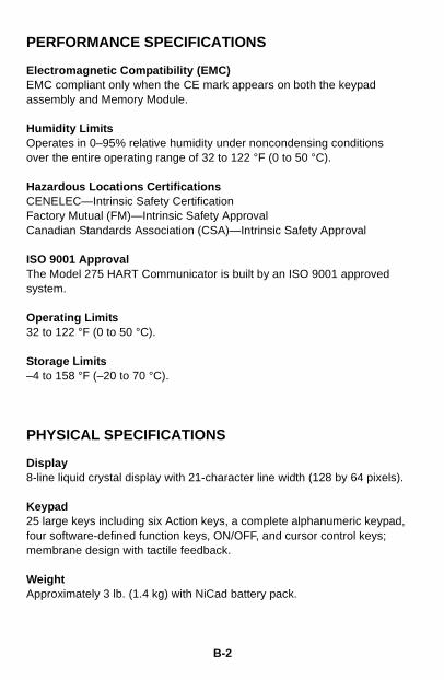
PERFORMANCE SPECIFICATIONS
Electromagnetic Compatibility (EMC)EMC compliant only when the CE mark appears on both the keypad assembly and Memory Module.
Humidity LimitsOperates in 0–95% relative humidity under noncondensing conditions over the entire operating range of 32 to 122 °F (0 to 50 °C).
Hazardous Locations CertificationsCENELEC—Intrinsic Safety CertificationFactory Mutual (FM)—Intrinsic Safety ApprovalCanadian Standards Association (CSA)—Intrinsic Safety Approval
ISO 9001 ApprovalThe Model 275 HART Communicator is built by an ISO 9001 approved system.
Operating Limits32 to 122 °F (0 to 50 °C).
Storage Limits–4 to 158 °F (–20 to 70 °C).
PHYSICAL SPECIFICATIONS
Display8-line liquid crystal display with 21-character line width (128 by 64 pixels).
Keypad25 large keys including six Action keys, a complete alphanumeric keypad, four software-defined function keys, ON/OFF, and cursor control keys; membrane design with tactile feedback.
WeightApproximately 3 lb. (1.4 kg) with NiCad battery pack.
B-2
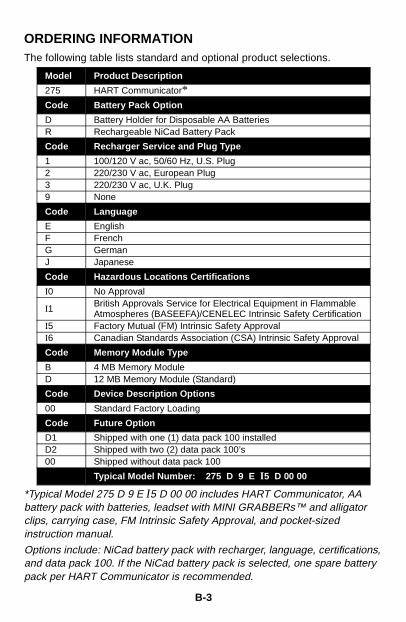
ORDERING INFORMATIONThe following table lists standard and optional product selections.
*Typical Model 275 D 9 E I5 D 00 00 includes HART Communicator, AA battery pack with batteries, leadset with MINI GRABBERs™ and alligator clips, carrying case, FM Intrinsic Safety Approval, and pocket-sized instruction manual.
Options include: NiCad battery pack with recharger, language, certifications, and data pack 100. If the NiCad battery pack is selected, one spare battery pack per HART Communicator is recommended.
Model Product Description
275 HART Communicator*Code Battery Pack Option
D Battery Holder for Disposable AA BatteriesR Rechargeable NiCad Battery Pack
Code Recharger Service and Plug Type
1 100/120 V ac, 50/60 Hz, U.S. Plug2 220/230 V ac, European Plug3 220/230 V ac, U.K. Plug9 None
Code Language
E EnglishF FrenchG GermanJ Japanese
Code Hazardous Locations Certifications
I0 No Approval
I1 British Approvals Service for Electrical Equipment in Flammable Atmospheres (BASEEFA)/CENELEC Intrinsic Safety Certification
I5 Factory Mutual (FM) Intrinsic Safety ApprovalI6 Canadian Standards Association (CSA) Intrinsic Safety Approval
Code Memory Module Type
B 4 MB Memory Module D 12 MB Memory Module (Standard)
Code Device Description Options
00 Standard Factory Loading
Code Future Option
D1 Shipped with one (1) data pack 100 installedD2 Shipped with two (2) data pack 100’s 00 Shipped without data pack 100
Typical Model Number: 275 D 9 E I5 D 00 00
B-3
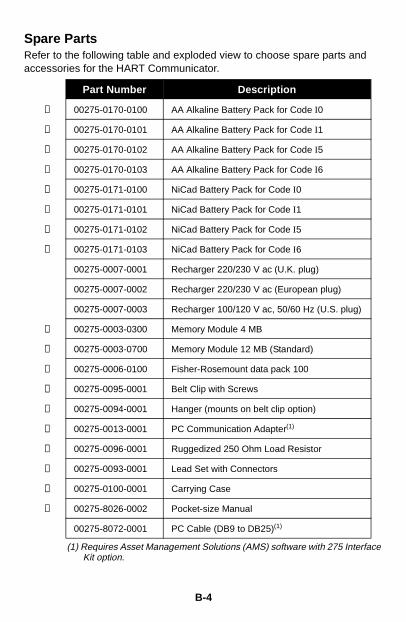
Spare PartsRefer to the following table and exploded view to choose spare parts and accessories for the HART Communicator.
(1) Requires Asset Management Solutions (AMS) software with 275 Interface Kit option.
Part Number Description
➀ 00275-0170-0100 AA Alkaline Battery Pack for Code I0
➀ 00275-0170-0101 AA Alkaline Battery Pack for Code I1
➀ 00275-0170-0102 AA Alkaline Battery Pack for Code I5
➀ 00275-0170-0103 AA Alkaline Battery Pack for Code I6
➀ 00275-0171-0100 NiCad Battery Pack for Code I0
➀ 00275-0171-0101 NiCad Battery Pack for Code I1
➀ 00275-0171-0102 NiCad Battery Pack for Code I5
➀ 00275-0171-0103 NiCad Battery Pack for Code I6
00275-0007-0001 Recharger 220/230 V ac (U.K. plug)
00275-0007-0002 Recharger 220/230 V ac (European plug)
00275-0007-0003 Recharger 100/120 V ac, 50/60 Hz (U.S. plug)
➁ 00275-0003-0300 Memory Module 4 MB
➁ 00275-0003-0700 Memory Module 12 MB (Standard)
③ 00275-0006-0100 Fisher-Rosemount data pack 100
④ 00275-0095-0001 Belt Clip with Screws
⑤ 00275-0094-0001 Hanger (mounts on belt clip option)
➅ 00275-0013-0001 PC Communication Adapter(1)
⑦ 00275-0096-0001 Ruggedized 250 Ohm Load Resistor
⑧ 00275-0093-0001 Lead Set with Connectors
⑨ 00275-0100-0001 Carrying Case
⑩ 00275-8026-0002 Pocket-size Manual
00275-8072-0001 PC Cable (DB9 to DB25)(1)
B-4
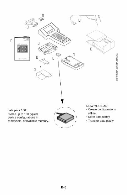
B-5
①
②④
⑤
⑥
⑦
HART® Communicator
MAN 4275A00English
October 1994⑩
275-
0275
J01A
, 027
5I01
A, 0
275L
01A
③
⑧
⑨
data pack 100:Stores up to 100 typicaldevice configurations inremovable, nonvolatile memory.
NOW YOU CAN:• Create configurations
• Store data safely• Transfer data easily
offline

B-6
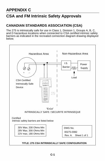
APPENDIX C
CSA and FM Intrinsic Safety Approvals
CANADIAN STANDARDS ASSOCIATION (CSA)The 275 is intrinsically safe for use in Class 1, Division 1, Groups A, B, C, and D hazardous locations when connected to CSA certified intrinsic safety barriers as indicated in the recreated connection diagram drawing displayed below.
I.S.
BarrierPower
Supply
Hazardous Area Non-Hazardous Area
CSA Certified
Intrinsically Safe
Device
00275-0082
DWG No.
Rev. A. Sheet 1 of 1
30V Max, 330 Ohms Min28V Max, 300 Ohms Min22V max, 180 Ohms Min
Certified intrinsic safety barriers are listed below
TITLE: 275 CSA INTRINSICALLY SAFE CONFIGURATION
“Ex1a”INTRINSICALLY SAFE / SECURITE INTRINSEQUE
Load
+ _
C-1
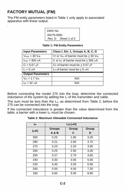
FACTORY MUTUAL (FM)The FM entity parameters listed in Table 1 only apply to associated apparatus with linear output..
Before connecting the model 275 into the loop, determine the connectedinductance of the system by adding the Li of the transmitter and cable.The sum must be less than the La, as determined from Table 2, before the275 can be connected into the loop.If the connected inductance is greater than the value determined from thetable, a barrier with a lower Isc must be chosen.
Table 1: FM Entity Parameters
Input Parameters Class I, Div. 1, Groups A, B, C, D
Vmax = 30 Vdc VT or Voc of barrier must be < 30 Vdc
Imax = 300 mA IT or Isc of barrier must be < 300 mA
Ci = 0.07 µF CA of barrier must be > 0.07 µF
Li = 0 mH LA of barrier must be > 0 mH
Output Parameters
Voc = 1.7 Vdc N/A
Isc = 32 mA N/A
Table 2: Maximum Allowable Connected Inductance
Im La (mH)
(mA)GroupsA & B
GroupC
GroupD
300 0.20 1.80 3.20
280 0.21 2.00 3.70
270 0.23 2.20 3.90
260 0.25 2.50 4.30
250 0.27 2.70 4.60
240 0.30 3.00 5.00
220 0.40 3.20 5.90
200 0.50 4.00 7.20
180 0.60 5.00 8.80
00275-0081
DWG No.
Rev. D. Sheet 1 of 2
C-2
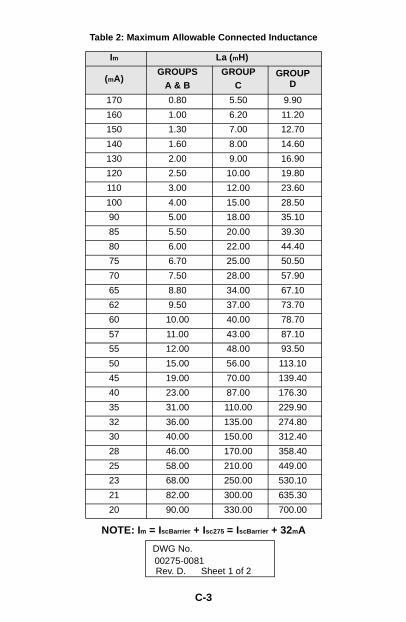
NOTE: Im = IscBarrier + Isc275 = IscBarrier + 32mA
(mA)GROUPS
A & BGROUP
CGROUP
D
170 0.80 5.50 9.90
160 1.00 6.20 11.20
150 1.30 7.00 12.70
140 1.60 8.00 14.60
130 2.00 9.00 16.90
120 2.50 10.00 19.80
110 3.00 12.00 23.60
100 4.00 15.00 28.50
90 5.00 18.00 35.10
85 5.50 20.00 39.30
80 6.00 22.00 44.40
75 6.70 25.00 50.50
70 7.50 28.00 57.90
65 8.80 34.00 67.10
62 9.50 37.00 73.70
60 10.00 40.00 78.70
57 11.00 43.00 87.10
55 12.00 48.00 93.50
50 15.00 56.00 113.10
45 19.00 70.00 139.40
40 23.00 87.00 176.30
35 31.00 110.00 229.90
32 36.00 135.00 274.80
30 40.00 150.00 312.40
28 46.00 170.00 358.40
25 58.00 210.00 449.00
23 68.00 250.00 530.10
21 82.00 300.00 635.30
20 90.00 330.00 700.00
Table 2: Maximum Allowable Connected Inductance
Im La (mH)
00275-0081DWG No.
Rev. D. Sheet 1 of 2
C-3
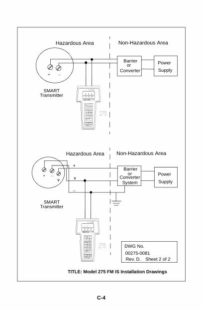
Barrier
Converter
Power
Supply
Hazardous Area Non-Hazardous Area
SMART
00275-0081
DWG No.
Rev. D. Sheet 2 of 2
TITLE: Model 275 FM IS Installation Drawings
or
Transmitter
Barrier
ConverterPower
Supply
Hazardous Area Non-Hazardous Area
SMART
or
Transmitter
System
+
V
_
+ _
+ _V
C-4
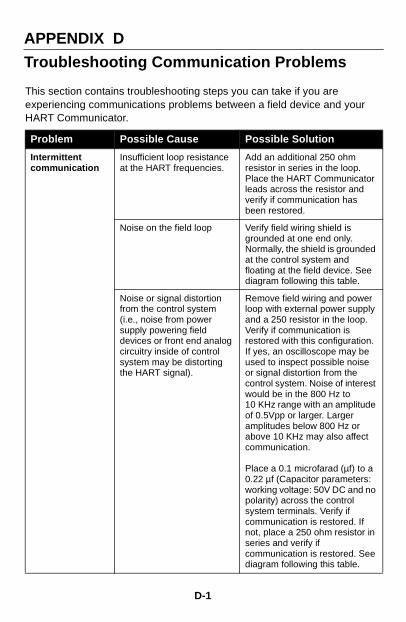
APPENDIX D
Troubleshooting Communication Problems
This section contains troubleshooting steps you can take if you are experiencing communications problems between a field device and your HART Communicator.
Problem Possible Cause Possible Solution
Intermittent communication
Insufficient loop resistance at the HART frequencies.
Add an additional 250 ohm resistor in series in the loop. Place the HART Communicator leads across the resistor and verify if communication has been restored.
Noise on the field loop Verify field wiring shield is grounded at one end only. Normally, the shield is grounded at the control system and floating at the field device. See diagram following this table.
Noise or signal distortion from the control system (i.e., noise from power supply powering field devices or front end analog circuitry inside of control system may be distorting the HART signal).
Remove field wiring and power loop with external power supply and a 250 resistor in the loop. Verify if communication is restored with this configuration. If yes, an oscilloscope may be used to inspect possible noise or signal distortion from the control system. Noise of interest would be in the 800 Hz to 10 KHz range with an amplitude of 0.5Vpp or larger. Larger amplitudes below 800 Hz or above 10 KHz may also affect communication.
Place a 0.1 microfarad (µf) to a 0.22 µf (Capacitor parameters: working voltage: 50V DC and no polarity) across the control system terminals. Verify if communication is restored. If not, place a 250 ohm resistor in series and verify if communication is restored. See diagram following this table.
D-1
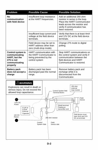
D-2
Problem Possible Cause Possible Solution
No communication with field device
Insufficient loop resistance at the HART frequencies.
Add an additional 250 ohm resistor in series in the loop. Place the HART Communicator leads across the resistor and verify if communication has been restored.
Insufficient loop current and voltage at the field device terminals.
Verify that there is at least 4mA and 12V DC at the field device terminals.
Field device may be set to HART address other than zero (multi-drop mode).
Change 275 mode to digital polling.
Control system is communicating HART, but the 275 is not communicating properly
HART communication with the HART Communicator is being prevented by the control system
Stop HART communications on the control system and verify if communication between the field devices and HART Communicator is restored.
Battery pack does not accept a charge
Battery pack has been discharged past the normal range.
Remove battery pack and recharge while it is disconnected from the Communicator.
+24V DCPower
250 ohm resistor
24V DCReturn
FieldDevice
Control System fieldTerminal blocks
0.1uF to0.22uFExternalCapacitor
Shield terminal.Floating attransmitter end
250 ohmexternalloop resistor
ControlSystem Side
FieldDevice side
Field device musthave 4mA and 12VDC at terminals
Explosions can result in death or serious injury. Do not exceed the allowed loop capacitance.
WARNING!
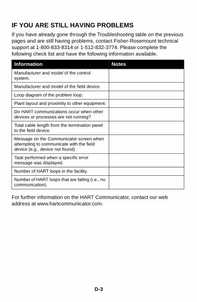
D-3
IF YOU ARE STILL HAVING PROBLEMSIf you have already gone through the Troubleshooting table on the previous pages and are still having problems, contact Fisher-Rosemount technical support at 1-800-833-8314 or 1-512-832-3774. Please complete the following check list and have the following information available.
For further information on the HART Communicator, contact our web address at www.hartcommunicator.com.
Information Notes
Manufacturer and model of the control system.
Manufacturer and model of the field device.
Loop diagram of the problem loop.
Plant layout and proximity to other equipment.
Do HART communications occur when other devices or processes are not running?
Total cable length from the termination panel to the field device.
Message on the Communicator screen when attempting to communicate with the field device (e.g., device not found).
Task performed when a specific error message was displayed.
Number of HART loops in the facility.
Number of HART loops that are failing (i.e., no communication).

D-4
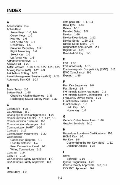
INDEX
AAccessories B-4Action Keys
Arrow Keys 1-5, 1-6Cursor Keys 1-6Hot Key 1-6Left Arrow Key 1-6On/Off Key 1-5Previous Menu Key 1-6Right Arrow Key 1-6Select Key 1-6Up Arrow Key 1-6
Alphanumeric Keys 1-8Always Poll 1-23AMS Software 1-18, 1-26, 1-27, 1-28, 1-29Analog Output (AO) 1-20, 2-3Ask before Polling 1-23Asset Management Solutions (AMS) 1-26Automatic Turn Off 1-24
BBasic Setup 2-5Battery Pack 1-35
Changing Alkaline Batteries 1-36Recharging NiCad Battery Pack 1-37
CCalibration 1-35CE Approval B-2Changing Stored Configurations 1-29Communication Adaptor 1-2, 1-27, B-1Communication Problems D-1Communicator Messages A-1Communicator, HART 1-10Compare 1-19Configuration Parameters 1-20Connections
Connection Diagram 1-2Load Resistance 1-4Rear Connection Panel 1-2Wiring Connections 1-2
Contrast 1-24Copy To 1-18CSA Intrinisc Safety Connection 1-4CSA Intrinsic Safety Approvals C-1
DData Entry 1-9
dDDDDDDDDDD
EEEEEE
FFFFFFFF
GGG
HHHH
II
III
I-
ata pack 100 1-1, B-4ata Type 1-16elete 1-18etailed Setup 2-5evice 1-20evice Descriptions 1-12evice Setup 1-20, 2-2evice Setup Menu 2-4iagnostics and Service 2-4igital Poll 1-23isabled Off Key 1-5
dit 1-18dit Individually 1-15lectromagnetic Compatibility (EMC) B-2MC Compliance B-2xpand 1-18
ast Key Sequence 2-6ast Select 1-8M Intrinsic Safety Approvals C-2M Intrinsic Safety Connections 1-4requency Device Menu 1-21unction Key Lables 1-7unction Keys 1-6
Help Key 1-6Home Key 1-7
eneric Online Menu Tree 1-20raphic Symbols 1-10
azardous Locations Certifications B-2OME Key 1-7ot Key 1-6
Customizing the Hot Key Menu 1-31Deleting Options 1-33
consSofware 1-10
gnore Diagnostics 1-25ntrinsic Safety Approvals B-3, C-1SO 9001 Approved B-2
1
KKeypad
Action Keys 1-5Alphanumeric keys 1-8Function Keys 1-6Hot Key 1-6Shift Keys 1-9
LLanguage Options B-3Liquid Crystal Display 1-4Listen for PC 1-17, 1-26Load Resistor 1-4, B-4Lower Range Value (LRV) 1-20, 2-3
MMain Menu 1-9, 1-12Memory Module 1-37
Replacing the Memory Module 1-38Menu Icons 1-10Menu Structure 1-11Messages A-1Microprocessors B-1Model Number B-3Model-Specific Routine Tasks 3-1
NNever Poll 1-23NIST 1-35
OOff Key Disabled 1-5Offline Configure
Field Device Revision Menu 1-14Manufacturer Menu 1-14, 1-28Model Menu 1-14
Offline Connections 1-9Offline Menu
New and Saved Configurations 1-13Offline Menu Tree 1-13ON/OFF Key 1-5Online Connections 1-9Online Help 1-6Online Menu 1-9Ordering Information B-3
PPC Interface 1-26Poll Using Tag 1-23Polling 1-23
I
Power Supply 1-10Primary Variable (PV) 1-20, 2-3Process Variables 2-4
RRecharging Batteries 1-37Rename 1-19Resistance in the Loop 1-3Resistor 1-4, B-4Reviewing Installed Devices 1-12
SSave 1-20Save As 1-16Save to data pack 1-16Save to Module 1-16Saved Configuration 1-17, 1-18Send 1-18Servicing the HART Communicator
Disassembly 1-35Memory Module 1-37
Shift Keys 1-8Simulation 1-28Software Icons 1-10Specifications
Hazardous Locations Certifications B-2Performance B-2Physical B-2
Storage Location 1-28Module and Data Pack 1-16
TTag 1-5Troubleshooting D-1
UUnmark All 1-15Upgrading Software 1-35Upper Range Value (URV) 1-20, 2-3Utility Menu 1-22
Auto Poll 1-22Contrast Adjustment 1-24
WWiring
Load Resistance 1-4
YYear 2000 Compliance 1-34
-2