Embed Size (px)
Citation preview
AT9000 Advanced Transmitter
Differential Pressure Transmitters
Specifications are subject to change without notice. - 1 - “This product is designed for general industrial use.”
5th edition
No. SS2-GTX00D-0500
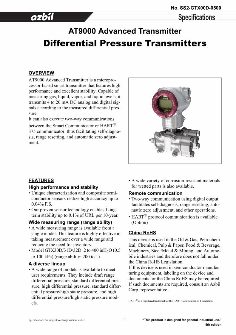
OVERVIEW
AT9000 Advanced Transmitter is a micropro-cessor-based smart transmitter that features high performance and excellent stability. Capable of measuring gas, liquid, vapor, and liquid levels, it transmits 4 to 20 mA DC analog and digital sig-nals according to the measured differential pres-sure.It can also execute two-way communications
between the Smart Communicator or HART® 375 communicator, thus facilitating self-diagno-sis, range resetting, and automatic zero adjust-ment.
FEATURES
High performance and stability • Unique characterization and composite semi-
conductor sensors realize high accuracy up to 0.04% F.S.
• Our proven sensor technology enables Long-term stability up to 0.1% of URL per 10-year.
Wide measuring range (range ability)• A wide measuring range is available from a
single model. This feature is highly effective in taking measurement over a wide range and reducing the need for inventory.
• Model GTX30D/31D/32D: 2 to 400 inH2O (0.5 to 100 kPa) (range ability: 200 to 1)
A diverse lineup• A wide range of models is available to meet
user requirements. They include draft range differential pressure, standard differential pres-sure, high differential pressure, standard differ-ential pressure/high static pressure, and high differential pressure/high static pressure mod-els.
• A wide variety of corrosion-resistant materials for wetted parts is also available.
Remote communication• Two-way communication using digital output
facilitates self-diagnosis, range resetting, auto-matic zero adjustment, and other operations.
• HART® protocol communication is available. (Option)
China RoHS
This device is used in the Oil & Gas, Petrochem-ical, Chemical, Pulp & Paper, Food & Beverage, Machinery, Steel/Metal & Mining, and Automo-bile industries and therefore does not fall under the China RoHS Legislation.If this device is used in semiconductor manufac-turing equipment, labeling on the device and documents for the China RoHS may be required. If such documents are required, consult an Azbil Corp. representative.
HART® is a registered trademark of the HART Communication Foundation.
No. SS2-GTX00D-0500 Azbil Corporation
- 2 -
FUNCTIONAL SPECIFICATIONS
FM Explosionproof and Dust Approvals(Code F1)Explosionproof for Class I, Division 1, Groups A, B, C and D; Class I, Zone 1, AEx d IICDust-Ignitionproof for Class II, III, Division 1, Groups E, F and GT5 -40°C < Tamb < +85°CHazardous locationsIndoor / Outdoor Type 4X, IP67Factory sealed, conduit seal not required for Division applicationsCaution - Use supply wires suitable for 5°C above sur-rounding ambient
FM Intrinsically safe Approval (Code F2)IS/I,II,III/1/ABCDEFG/T4; -40 °C < Tamb < +60 °C; 80395278, 80395279,80395280; Entity; TYPE 4X; IP67 I/0/ AEx ia/IIC/T4; -40 °C < Tamb < +60 °C;80395278, 80395279, 80395280; Entity; TYPE 4X;IP67Entity Parameters: Vmax(Ui)=30 Volts, Imax(Ii)=100mA, Pi=1W, Ci=10nF, Li=0.5mH
FM Nonincendive Approval(Code F5)NI/I/2/ABCD/T4; -40 °C < Tamb < +60 °C;80395494; NIFW; TYPE 4X; IP67 NI/I/2/IIC/T4; -40 °C < Tamb < +60 °C; 80395494; NIFW; TYPE 4X; IP67S/II,III/1/EFG/T4; -40 °C < Tamb < +60 °C; 80395494;NIFW; TYPE 4X; P67Nonincendive Field Wiring Parameters: Vmax(Ui)=30 Volts, Ci=10nF, Li=0.5mH
Combination of F1, F2 and F5(Code F6)
ATEX Flameproof and Dust Certifications(Code A1)
0344 KEMA 08ATEX0004
II 1/2 G Ex d IIC T6 Tprocess=85°C -30°C < Tamb < +75°C IP66/67II 1/2 G Ex d IIC T5 Tprocess=100°C -30°C < Tamb < +80°C IP66/67II 1/2 G Ex d IIC T4 Tprocess=110°C -30°C < Tamb < +80°C IP66/67II 2 D Ex tD A21 IP66/67 T85 Tprocess=85°C -30°C < Tamb < +75°CII 2 D Ex tD A21 IP66/67 T100 Tprocess=100°C -30°C < Tamb < +75°CII 2 D Ex tD A21 IP66/67 T110 Tprocess=110°C -30°C < Tamb < +75°CCaution - Use supply wires suitable for 5°C above sur-rounding ambient
ATEX Intrinsic safety and Dust Certifications (Code A2)
0344 KEMA 07ATEX0200 X
II 1 G Ex ia IIC T4 TPROCESS = 105 °C -30 °C < Tamb < +60 °C IP66 / 67ELECTRICAL PARAMETERS: Ui = 30 V, Ii = 93 mA,
Pi = 1 W, Ci = 5 nF, Li = 0.5 mHII 1 D Ex iaD 20 IP66 / 67 T105 TPROCESS = 105 °C -30 °C < Tamb < +60 °C
ATEX Type n and Dust Certifications(Code A5)
0344 KEMA 07ATEX0200 X
II 3 G Ex nL IIC T4 TPROCESS = 105 °C -30 °C < Tamb < +60 °C IP66 / 67ELECTRICAL PARAMETERS: Ui = 30 V, Ci = 5 nF, Li = 0.5 mHII 2 D Ex tD A21 IP66 / 67 T85 TPROCESS = 85 °C -30 °C < Tamb < +75 °CII 2 D Ex tD A21 IP66 / 67 T100 TPROCESS = 100 °C -30 °C < Tamb < +80 °CII 2 D Ex tD A21 IP66 / 67 T110 TPROCESS = 110 °C -30 °C < Tamb < +80 °C
NEPSI Flameproof and Dust Certifications (Code N1)Ex d IIC T6 DIP A21 TA 85°C Tprocess=80°C -40°C < Tamb < +75°CEx d IIC T5 DIP A21 TA 100°C Tprocess=95°C -40°C < Tamb < +80°CEx d IIC T4 DIP A21 TA 115°C Tprocess=110°C -40°C < Tamb < +80°CENCLOSURE TYPE IP66/67
NEPSI Intrinsic Safety Certification(Code N2)Ex ia IIC T4 Tprocess=105°C -40°C < Tamb < +60°CEnclosure IP66 / 67Electrical Parameters: Ui=30V, Ii=100mA, Pi=1W, Ci=13nF, Li=0.5mH
NEPSI Type n Certification(Code N5)Ex nL IIC T4 Tprocess=110°C -40°C < Tamb < +60°CEnclosure IP66 / 67Electrical Parameters: Ui=30V, Ii=100mA, Pi=1W, Ci=13nF, Li=0.5mH
IECEx Flameproof and Dust Certifications(Code E1)Certificate No. IECEx KEM 08.0001Ga/Gb Ex d IIC T6 Tprocess=85°C -30°C < Tamb < +75°C IP66/67Ga/Gb Ex d IIC T5 Tprocess=100°C -30°C < Tamb < +80°C IP66/67Ga/Gb Ex d IIC T4 Tprocess=110°C -30°C < Tamb < +80°C IP66/67Ex tD A21 IP66/67 T85 Tprocess=85°C -30°C < Tamb < +75°CEx tD A21 IP66/67 T100 Tprocess=100°C -30°C < Tamb < +75°CEx tD A21 IP66/67 T110 Tprocess=110°C -30°C < Tamb < +75°CCaution - Use supply wires suitable for 5°C above sur-rounding ambient
Azbil Corporation No. SS2-GTX00D-0500
- 3 -
IECEx Intrinsic safety and Dust Certifications(Code E2) IECEx KEM 07.0058XZone 0 Ex ia IIC T4 TPROCESS = 105 °C
-30 °C < Tamb < +60 °C IP66 / 67ELECTRICAL PARAMETERS: Ui = 30 V, Ii = 93 mA, Pi = 1 W, Ci = 5 nF, Li = 0.5 mH
Ex iaD 20 IP66 / 67 T105 TPROCESS = 105 °C -30 °C < Tamb < +60 °C
IECEx Type n and Dust Certifications (Code E5)IECEx KEM 07.0058XEx nL IIC T4 TPROCESS = 105 °C -30 °C < Tamb < +60 °C IP66 / 67ELECTRICAL PARAMETERS: Ui = 30 V, Ci = 5 nF, Li = 0.5 mHEx tD A21 IP66 / 67 T85 TPROCESS = 85 °C -30 °C < Tamb < +75 °CEx tD A21 IP66 / 67 T100 TPROCESS = 100 °C -30 °C < Tamb < +80 °CEx tD A21 IP66 / 67 T110 TPROCESS = 110 °C -30 °C < Tamb < +80 °C
EMC Conformity89/336/EEC, 92/31/EEC, 93/68/EEC Electromagnetic Compatibility (EMC) Directive
PED Conformity (97/23EC)The maximum pressures applicable under the Sound Engi-neering Practice (SEP) section of the Pressure Equipment Directive depend on the type of fluid measured, as shown in the table below.
Note) Group 1 comprises fluids defines as: explosive, extremely flammable, highly flammable, flammable, very toxic, toxic and oxidizing.Group 2 comprises all other fluids not refer to group 1
Any AT9000 model having a maximum working pressure that is higher than the pressure corresponding to its group does not conform to SEP.Models GTX32D, 42D, 72D and 82G conform to PED according to Module A.
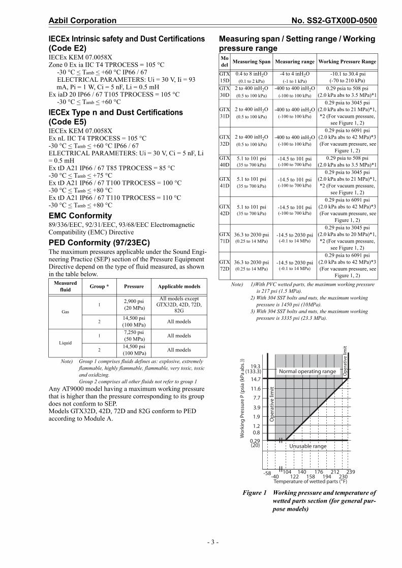
Measuring span / Setting range / Working pressure range
Note) 1)With PVC wetted parts, the maximum working pressure is 217 psi (1.5 MPa).
2) With 304 SST bolts and nuts, the maximum working pressure is 1450 psi (10MPa).
3) With 304 SST bolts and nuts, the maximum working pressure is 3335 psi (23.3 MPa).
Figure 1 Working pressure and temperature of wetted parts section (for general pur-pose models)
Measured fluid
Group * Pressure Applicable models
Gas
12,900 psi (20 MPa)
All models except GTX32D, 42D, 72D,
82G
214,500 psi (100 MPa)
All models
Liquid
17,250 psi (50 MPa)
All models
214,500 psi (100 MPa)
All models
Model
Measuring Span Measuring range Working Pressure Range
GTX15D
0.4 to 8 inH2O(0.1 to 2 kPa)
-4 to 4 inH2O(-1 to 1 kPa)
-10.1 to 30.4 psi(-70 to 210 kPa)
GTX30D
2 to 400 inH2O(0.5 to 100 kPa)
-400 to 400 inH2O(-100 to 100 kPa)
0.29 psia to 508 psi(2.0 kPa abs to 3.5 MPa)*1
GTX31D
2 to 400 inH2O(0.5 to 100 kPa)
-400 to 400 inH2O(-100 to 100 kPa)
0.29 psia to 3045 psi(2.0 kPa abs to 21 MPa)*1, *2 (For vacuum pressure,
see Figure 1, 2)
GTX32D
2 to 400 inH2O(0.5 to 100 kPa)
-400 to 400 inH2O(-100 to 100 kPa)
0.29 psia to 6091 psi(2.0 kPa abs to 42 MPa)*3 (For vacuum pressure, see
Figure 1, 2)GTX40D
5.1 to 101 psi(35 to 700 kPa)
-14.5 to 101 psi(-100 to 700 kPa)
0.29 psia to 508 psi(2.0 kPa abs to 3.5 MPa)*1
GTX41D
5.1 to 101 psi(35 to 700 kPa)
-14.5 to 101 psi(-100 to 700 kPa)
0.29 psia to 3045 psi(2.0 kPa abs to 21 MPa)*1, *2 (For vacuum pressure,
see Figure 1, 2)
GTX42D
5.1 to 101 psi(35 to 700 kPa)
-14.5 to 101 psi(-100 to 700 kPa)
0.29 psia to 6091 psi(2.0 kPa abs to 42 MPa)*3 (For vacuum pressure, see
Figure 1, 2)
GTX71D
36.3 to 2030 psi(0.25 to 14 MPa)
-14.5 to 2030 psi(-0.1 to 14 MPa)
0.29 psia to 3045 psi(2.0 kPa abs to 20 MPa)*1, *2 (For vacuum pressure,
see Figure 1, 2)
GTX72D
36.3 to 2030 psi(0.25 to 14 MPa)
-14.5 to 2030 psi(-0.1 to 14 MPa)
0.29 psia to 6091 psi(2.0 kPa abs to 42 MPa)*3 (For vacuum pressure, see
Figure 1, 2)
19.3(133.3)
14.7
11.6
7.7
3.9
1.9
1.20.8
0.29(20)
-58-40
104122
140158
176194
212230
239
Normal operating range
Op
erat
ive
limit
Unusable range
Op
erat
ive
limit
Temperature of wetted parts ( F)
Wo
rkin
g P
ress
ure
P (p
sia
(kPa
ab
s. ))
No. SS2-GTX00D-0500 Azbil Corporation
- 4 -
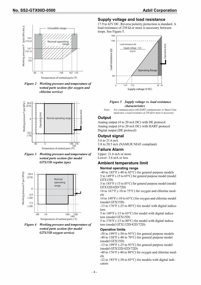
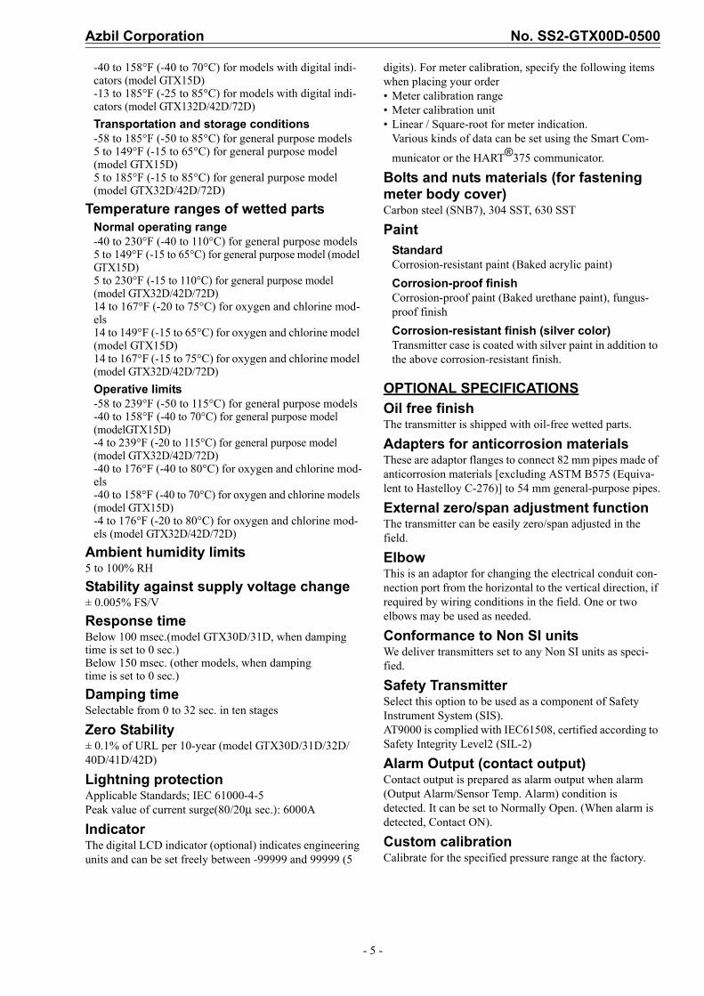
Figure 2 Working pressure and temperature of wetted parts section (for oxygen and chlorine service)
Figure 3 Working pressure and temperature of wetted parts section (for model GTX15D regular type)
Figure 4 Working pressure and temperature of wetted parts section (for model GTX15D oxygen service)
Supply voltage and load resistance17.9 to 42V DC. Reverse polarity protection is standard. A load resistance of 250 Ω or more is necessary between loops. See Figure 5.
Figure 5 Supply voltage vs. load resistance characteristics
Note) For communication with HART communicator or Smart Com-municator, a load resistance of 250 Ω or more is necessary.
OutputAnalog output (4 to 20 mA DC) with DE protocolAnalog output (4 to 20 mA DC) with HART protocolDigital output (DE protocol)
Output signal3.6 to 21.6 mA3.8 to 20.5 mA (NAMUR NE43 compliant)
Failure AlarmUpper: 21.6 mA or moreLower: 3.6 mA or less
Ambient temperature limitNormal operating range-40 to 185°F (-40 to 85°C) for general purpose models5 to 149°F (-15 to 65°C) for general purpose model (model GTX15D)5 to 185°F (-15 to 85°C) for general purpose model (model GTX32D/42D/72D)14 to 167°F (-10 to 75°C) for oxygen and chlorine mod-els14 to 149°F (-10 to 65°C) for oxygen and chlorine model (model GTX15D)-13 to 176°F (-25 to 80°C) for model with digital indica-tors5 to 149°F (-15 to 65°C) for model with digital indica-tors (model GTX15D)5 to 176°F (-15 to 80°C) for model with digital indica-tors (model GTX132D/42D/72D)
Operative limits-58 to 199°F (-50 to 93°C) for general purpose models-40 to 158°F (-40 to 70°C) for general purpose model (model GTX15D)-13 to 199°F (-25 to 93°C) for general purpose model (model GTX32D/42D/72D)-40 to 176°F (-40 to 80°C) for oxygen and chlorine mod-els-22 to 185°F (-30 to 85°C) for models with digital indi-cators
19.3
14.7
7.7
-40 14 104 167 176
Normal operating range
Wo
rkin
g p
ress
ure
P
(psi
a (k
Pa a
bs.
))
Temperature of wetted parts ( F)
Unusable range
(133.3)
(101.3)
(53)
30.4(210)
0
-10.2(-70)
-40 5 149158
176
Temperature of wetted parts ( F)
Wor
king
pre
ssur
e P
(psi
(kPa
) )
Normal operating range
Ope
ratin
g lim
it
Ope
rativ
e lim
it
Normaloperatingrange
30.4 (210)
0
-2.9(-20)
-7.3(-50)
-40 -14 104149
158
Temperature of wetted parts ( F)
Wo
rkin
g p
ress
ure
P (p
si (k
Pa))
1345
1482
Load resistance (Ω)
Supply voltage - 12.5
0.0219
245
0 17.9 42 45
Load
resi
stan
ce (Ω
)
Supply voltage (V DC)
Operating Range
=
Ope
rativ
e lim
it
12.5
Azbil Corporation No. SS2-GTX00D-0500
- 5 -
-40 to 158°F (-40 to 70°C) for models with digital indi-cators (model GTX15D)-13 to 185°F (-25 to 85°C) for models with digital indi-cators (model GTX132D/42D/72D)
Transportation and storage conditions-58 to 185°F (-50 to 85°C) for general purpose models5 to 149°F (-15 to 65°C) for general purpose model (model GTX15D)5 to 185°F (-15 to 85°C) for general purpose model (model GTX32D/42D/72D)
Temperature ranges of wetted partsNormal operating range-40 to 230°F (-40 to 110°C) for general purpose models5 to 149°F (-15 to 65°C) for general purpose model (model GTX15D)5 to 230°F (-15 to 110°C) for general purpose model (model GTX32D/42D/72D)14 to 167°F (-20 to 75°C) for oxygen and chlorine mod-els14 to 149°F (-15 to 65°C) for oxygen and chlorine model (model GTX15D)14 to 167°F (-15 to 75°C) for oxygen and chlorine model (model GTX32D/42D/72D)
Operative limits-58 to 239°F (-50 to 115°C) for general purpose models-40 to 158°F (-40 to 70°C) for general purpose model (modelGTX15D)-4 to 239°F (-20 to 115°C) for general purpose model (model GTX32D/42D/72D)-40 to 176°F (-40 to 80°C) for oxygen and chlorine mod-els-40 to 158°F (-40 to 70°C) for oxygen and chlorine models (model GTX15D)-4 to 176°F (-20 to 80°C) for oxygen and chlorine mod-els (model GTX32D/42D/72D)
Ambient humidity limits5 to 100% RH
Stability against supply voltage change± 0.005% FS/V
Response time Below 100 msec.(model GTX30D/31D, when damping time is set to 0 sec.)Below 150 msec. (other models, when dampingtime is set to 0 sec.)
Damping timeSelectable from 0 to 32 sec. in ten stages
Zero Stability± 0.1% of URL per 10-year (model GTX30D/31D/32D/40D/41D/42D)
Lightning protectionApplicable Standards; IEC 61000-4-5Peak value of current surge(80/20μ sec.): 6000A
IndicatorThe digital LCD indicator (optional) indicates engineering units and can be set freely between -99999 and 99999 (5
digits). For meter calibration, specify the following items when placing your order• Meter calibration range• Meter calibration unit• Linear / Square-root for meter indication.
Various kinds of data can be set using the Smart Com-
municator or the HART®375 communicator.
Bolts and nuts materials (for fastening meter body cover)Carbon steel (SNB7), 304 SST, 630 SST
PaintStandardCorrosion-resistant paint (Baked acrylic paint)
Corrosion-proof finishCorrosion-proof paint (Baked urethane paint), fungus-proof finish
Corrosion-resistant finish (silver color) Transmitter case is coated with silver paint in addition to the above corrosion-resistant finish.
OPTIONAL SPECIFICATIONS
Oil free finishThe transmitter is shipped with oil-free wetted parts.
Adapters for anticorrosion materialsThese are adaptor flanges to connect 82 mm pipes made of anticorrosion materials [excluding ASTM B575 (Equiva-lent to Hastelloy C-276)] to 54 mm general-purpose pipes.
External zero/span adjustment functionThe transmitter can be easily zero/span adjusted in the field.
ElbowThis is an adaptor for changing the electrical conduit con-nection port from the horizontal to the vertical direction, if required by wiring conditions in the field. One or two elbows may be used as needed.
Conformance to Non SI unitsWe deliver transmitters set to any Non SI units as speci-fied.
Safety TransmitterSelect this option to be used as a component of Safety Instrument System (SIS).AT9000 is complied with IEC61508, certified according to Safety Integrity Level2 (SIL-2)
Alarm Output (contact output)Contact output is prepared as alarm output when alarm (Output Alarm/Sensor Temp. Alarm) condition is detected. It can be set to Normally Open. (When alarm is detected, Contact ON).
Custom calibrationCalibrate for the specified pressure range at the factory.
No. SS2-GTX00D-0500 Azbil Corporation
- 6 -
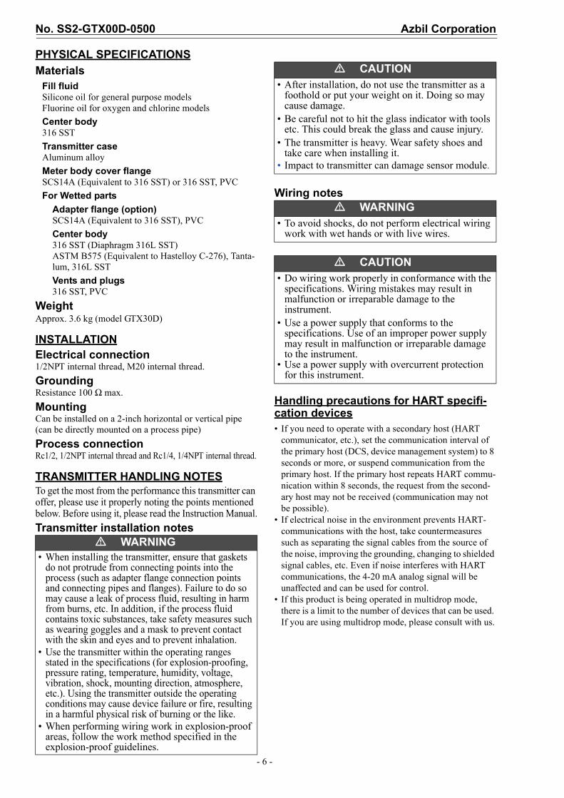
PHYSICAL SPECIFICATIONS
MaterialsFill fluidSilicone oil for general purpose modelsFluorine oil for oxygen and chlorine models
Center body316 SST
Transmitter caseAluminum alloy
Meter body cover flangeSCS14A (Equivalent to 316 SST) or 316 SST, PVC
For Wetted parts
Adapter flange (option) SCS14A (Equivalent to 316 SST), PVC
Center body316 SST (Diaphragm 316L SST)ASTM B575 (Equivalent to Hastelloy C-276), Tanta-lum, 316L SST
Vents and plugs316 SST, PVC
WeightApprox. 3.6 kg (model GTX30D)
INSTALLATIONElectrical connection1/2NPT internal thread, M20 internal thread.
GroundingResistance 100 Ω max.
MountingCan be installed on a 2-inch horizontal or vertical pipe (can be directly mounted on a process pipe)
Process connectionRc1/2, 1/2NPT internal thread and Rc1/4, 1/4NPT internal thread.
TRANSMITTER HANDLING NOTESTo get the most from the performance this transmitter can offer, please use it properly noting the points mentioned below. Before using it, please read the Instruction Manual.
Transmitter installation notes
Wiring notes
Handling precautions for HART specifi-cation devices• If you need to operate with a secondary host (HART
communicator, etc.), set the communication interval of the primary host (DCS, device management system) to 8 seconds or more, or suspend communication from the primary host. If the primary host repeats HART commu-nication within 8 seconds, the request from the second-ary host may not be received (communication may not be possible).
• If electrical noise in the environment prevents HART-communications with the host, take countermeasures such as separating the signal cables from the source of the noise, improving the grounding, changing to shielded signal cables, etc. Even if noise interferes with HART communications, the 4-20 mA analog signal will be unaffected and can be used for control.
• If this product is being operated in multidrop mode, there is a limit to the number of devices that can be used. If you are using multidrop mode, please consult with us.
� WARNING• When installing the transmitter, ensure that gaskets
do not protrude from connecting points into the process (such as adapter flange connection points and connecting pipes and flanges). Failure to do so may cause a leak of process fluid, resulting in harm from burns, etc. In addition, if the process fluid contains toxic substances, take safety measures such as wearing goggles and a mask to prevent contact with the skin and eyes and to prevent inhalation.
• Use the transmitter within the operating ranges stated in the specifications (for explosion-proofing, pressure rating, temperature, humidity, voltage, vibration, shock, mounting direction, atmosphere, etc.). Using the transmitter outside the operating conditions may cause device failure or fire, resulting in a harmful physical risk of burning or the like.
• When performing wiring work in explosion-proof areas, follow the work method specified in the explosion-proof guidelines.
� CAUTION• After installation, do not use the transmitter as a
foothold or put your weight on it. Doing so may cause damage.
• Be careful not to hit the glass indicator with tools etc. This could break the glass and cause injury.
• The transmitter is heavy. Wear safety shoes and take care when installing it.
• Impact to transmitter can damage sensor module.
� WARNING• To avoid shocks, do not perform electrical wiring
work with wet hands or with live wires.
� CAUTION• Do wiring work properly in conformance with the
specifications. Wiring mistakes may result in malfunction or irreparable damage to the instrument.
• Use a power supply that conforms to the specifications. Use of an improper power supply may result in malfunction or irreparable damage to the instrument.
• Use a power supply with overcurrent protection for this instrument.
Azbil Corporation No. SS2-GTX00D-0500
- 7 -
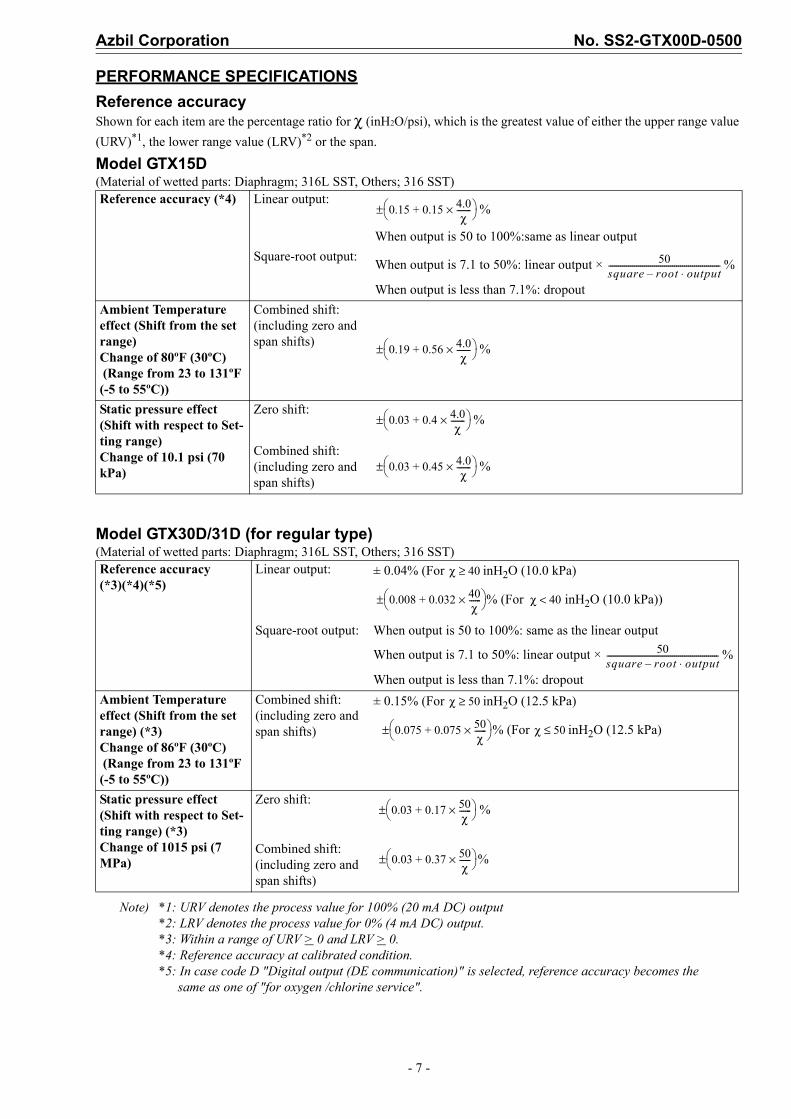
PERFORMANCE SPECIFICATIONS
Reference accuracyShown for each item are the percentage ratio for χ (inH2O/psi), which is the greatest value of either the upper range value
(URV)*1, the lower range value (LRV)*2 or the span.
Model GTX15D(Material of wetted parts: Diaphragm; 316L SST, Others; 316 SST)
Model GTX30D/31D (for regular type)(Material of wetted parts: Diaphragm; 316L SST, Others; 316 SST)
Note) *1: URV denotes the process value for 100% (20 mA DC) output*2: LRV denotes the process value for 0% (4 mA DC) output.*3: Within a range of URV > 0 and LRV > 0.*4: Reference accuracy at calibrated condition.*5: In case code D "Digital output (DE communication)" is selected, reference accuracy becomes the
same as one of "for oxygen /chlorine service".
Reference accuracy (*4) Linear output:%
When output is 50 to 100%:same as linear output
Square-root output:When output is 7.1 to 50%: linear output × %
When output is less than 7.1%: dropout
Ambient Temperature effect (Shift from the set range) Change of 80ºF (30ºC) (Range from 23 to 131ºF (-5 to 55ºC))
Combined shift:(including zero and span shifts)
%
Static pressure effect (Shift with respect to Set-ting range)Change of 10.1 psi (70 kPa)
Zero shift:%
Combined shift:(including zero and span shifts)
%
Reference accuracy (*3)(*4)(*5)
Linear output: ± 0.04% (For inH2O (10.0 kPa)
% (For inH2O (10.0 kPa))
Square-root output: When output is 50 to 100%: same as the linear output
When output is 7.1 to 50%: linear output × %
When output is less than 7.1%: dropout
Ambient Temperature effect (Shift from the set range) (*3) Change of 86ºF (30ºC) (Range from 23 to 131ºF (-5 to 55ºC))
Combined shift: (including zero and span shifts)
± 0.15% (For inH2O (12.5 kPa)
% (For inH2O (12.5 kPa)
Static pressure effect(Shift with respect to Set-ting range) (*3) Change of 1015 psi (7 MPa)
Zero shift:%
Combined shift: (including zero and span shifts)
%
0.15 0.15 4.0χ
-------×+ ±
50square root– output⋅--------------------------------------------------------
0.19 0.56 4.0χ
-------×+ ±
0.03 0.4 4.0χ
-------×+ ±
0.03 0.45 4.0χ
-------×+ ±
χ 40≥
0.008 0.032 40χ------×+
± χ 40<
50square root– output⋅--------------------------------------------------------
χ 50≥
0.075 0.075 50χ------×+
± χ 50≤
0.03 0.17 50χ------×+
±
0.03 0.37 50χ------×+
±
No. SS2-GTX00D-0500 Azbil Corporation
- 8 -
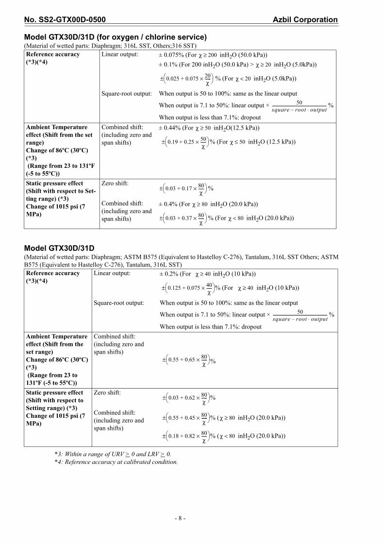
Model GTX30D/31D (for oxygen / chlorine service)(Material of wetted parts: Diaphragm; 316L SST, Others;316 SST)
Model GTX30D/31D(Material of wetted parts: Diaphragm; ASTM B575 (Equivalent to Hastelloy C-276), Tantalum, 316L SST Others; ASTM B575 (Equivalent to Hastelloy C-276), Tantalum, 316L SST)
*3: Within a range of URV > 0 and LRV > 0.*4: Reference accuracy at calibrated condition.
Reference accuracy (*3)(*4)
Linear output: ± 0.075% (For inH2O (50.0 kPa))
± 0.1% (For 200 inH2O (50.0 kPa) > inH2O (5.0kPa))
% (For inH2O (5.0kPa))
Square-root output: When output is 50 to 100%: same as the linear output
When output is 7.1 to 50%: linear output × %
When output is less than 7.1%: dropout
Ambient Temperature effect (Shift from the set range) Change of 86ºC (30ºC) (*3) (Range from 23 to 131ºF (-5 to 55ºC))
Combined shift: (including zero and span shifts)
± 0.44% (For inH2O(12.5 kPa))
% (For inH2O (12.5 kPa))
Static pressure effect (Shift with respect to Set-ting range) (*3)Change of 1015 psi (7 MPa)
Zero shift:%
Combined shift: (including zero and span shifts)
± 0.4% (For inH2O (20.0 kPa))
% (For inH2O (20.0 kPa))
Reference accuracy (*3)(*4)
Linear output: ± 0.2% (For inH2O (10 kPa))
% (For inH2O (10 kPa))
Square-root output: When output is 50 to 100%: same as the linear output
When output is 7.1 to 50%: linear output × %
When output is less than 7.1%: dropout
Ambient Temperature effect (Shift from the set range) Change of 86ºC (30ºC) (*3) (Range from 23 to 131ºF (-5 to 55ºC))
Combined shift: (including zero and span shifts)
%
Static pressure effect(Shift with respect to Setting range) (*3)Change of 1015 psi (7 MPa)
Zero shift:%
Combined shift: (including zero and span shifts)
% ( inH2O (20.0 kPa))
% ( inH2O (20.0 kPa))
χ 200≥
χ 20≥
0.025 0.075 20χ------×+
± χ 20<
50square root– output⋅--------------------------------------------------------
χ 50≥
0.19 0.25 50χ------×+
± χ 50≤
0.03 0.17 80χ------×+
±
χ 80≥
0.03 0.37 80χ------×+
± χ 80<
χ 40≥
0.125 0.075 40χ------×+
± χ 40≥
50square root– output⋅--------------------------------------------------------
0.55 0.65 80χ------×+
±
0.03 0.62 80χ------×+
±
0.55 0.45 80χ------×+
± χ 80≥
0.18 0.82 80χ------×+
± χ 80<
Azbil Corporation No. SS2-GTX00D-0500
- 9 -
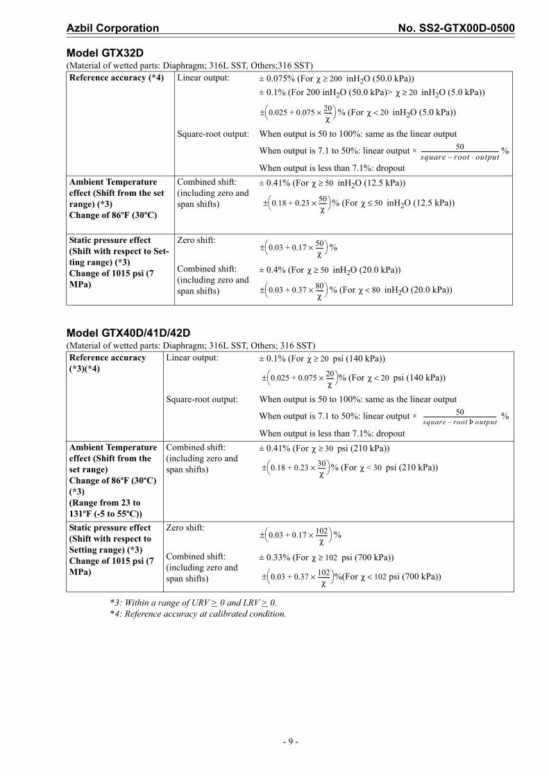
Model GTX32D (Material of wetted parts: Diaphragm; 316L SST, Others;316 SST)
Model GTX40D/41D/42D(Material of wetted parts: Diaphragm; 316L SST, Others; 316 SST)
*3: Within a range of URV > 0 and LRV > 0.*4: Reference accuracy at calibrated condition.
Reference accuracy (*4) Linear output: ± 0.075% (For inH2O (50.0 kPa))
± 0.1% (For 200 inH2O (50.0 kPa)> inH2O (5.0 kPa))
% (For inH2O (5.0 kPa))
Square-root output: When output is 50 to 100%: same as the linear output
When output is 7.1 to 50%: linear output × %
When output is less than 7.1%: dropout
Ambient Temperature effect (Shift from the set range) (*3)Change of 86ºF (30ºC)
Combined shift: (including zero and span shifts)
± 0.41% (For inH2O (12.5 kPa))
% (For inH2O (12.5 kPa))
Static pressure effect (Shift with respect to Set-ting range) (*3)Change of 1015 psi (7 MPa)
Zero shift:%
Combined shift: (including zero and span shifts)
± 0.4% (For inH2O (20.0 kPa))
% (For inH2O (20.0 kPa))
Reference accuracy (*3)(*4)
Linear output: ± 0.1% (For psi (140 kPa))
% (For psi (140 kPa))
Square-root output: When output is 50 to 100%: same as the linear output
When output is 7.1 to 50%: linear output × %
When output is less than 7.1%: dropout
Ambient Temperature effect (Shift from the set range) Change of 86ºF (30ºC) (*3)(Range from 23 to 131ºF (-5 to 55ºC))
Combined shift: (including zero and span shifts)
± 0.41% (For psi (210 kPa))
% (For psi (210 kPa))
Static pressure effect (Shift with respect to Setting range) (*3)Change of 1015 psi (7 MPa)
Zero shift:%
Combined shift: (including zero and span shifts)
± 0.33% (For psi (700 kPa))
%(For psi (700 kPa))
χ 200≥
χ 20≥
0.025 0.075 20χ------×+
± χ 20<
50square root– output⋅--------------------------------------------------------
χ 50≥
0.18 0.23 50χ------×+
± χ 50≤
0.03 0.17 50χ------×+
±
χ 50≥
0.03 0.37 80χ------×+
± χ 80<
χ 20≥
0.025 0.075 20χ------×+
± χ 20<
50square root– outputÞ-----------------------------------------------------
χ 30≥
0.18 0.23 30χ------×+
± χ 30<
0.03 0.17 102χ
---------×+ ±
χ 102≥
0.03 0.37 102χ
---------×+ ± χ 102<
No. SS2-GTX00D-0500 Azbil Corporation
- 10 -
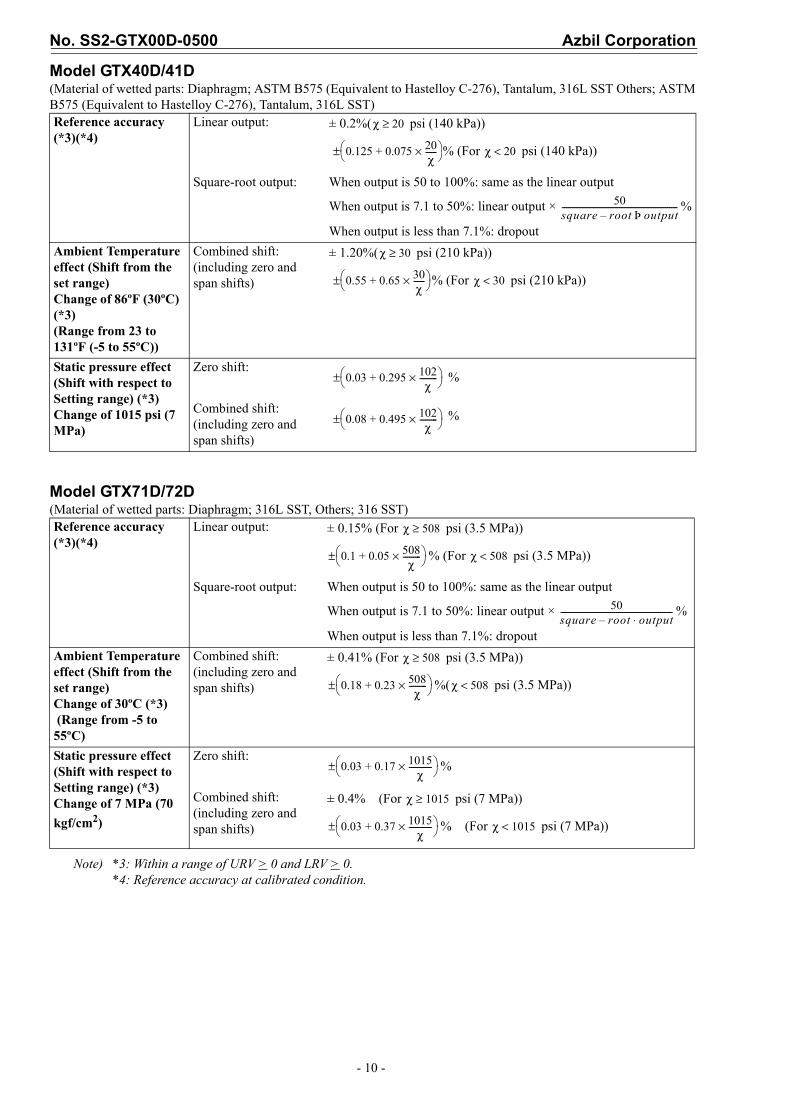
Model GTX40D/41D(Material of wetted parts: Diaphragm; ASTM B575 (Equivalent to Hastelloy C-276), Tantalum, 316L SST Others; ASTM B575 (Equivalent to Hastelloy C-276), Tantalum, 316L SST)
Model GTX71D/72D(Material of wetted parts: Diaphragm; 316L SST, Others; 316 SST)
Note) *3: Within a range of URV > 0 and LRV > 0.*4: Reference accuracy at calibrated condition.
Reference accuracy (*3)(*4)
Linear output: ± 0.2%( psi (140 kPa))
% (For psi (140 kPa))
Square-root output: When output is 50 to 100%: same as the linear output
When output is 7.1 to 50%: linear output × %
When output is less than 7.1%: dropout
Ambient Temperature effect (Shift from the set range) Change of 86ºF (30ºC) (*3)(Range from 23 to 131ºF (-5 to 55ºC))
Combined shift: (including zero and span shifts)
± 1.20%( psi (210 kPa))
% (For psi (210 kPa))
Static pressure effect(Shift with respect to Setting range) (*3)Change of 1015 psi (7 MPa)
Zero shift:%
Combined shift: (including zero and span shifts)
%
Reference accuracy (*3)(*4)
Linear output: ± 0.15% (For psi (3.5 MPa))
% (For psi (3.5 MPa))
Square-root output: When output is 50 to 100%: same as the linear output
When output is 7.1 to 50%: linear output × %
When output is less than 7.1%: dropout
Ambient Temperature effect (Shift from the set range) Change of 30ºC (*3) (Range from -5 to 55ºC)
Combined shift: (including zero and span shifts)
± 0.41% (For psi (3.5 MPa))
%( psi (3.5 MPa))
Static pressure effect (Shift with respect to Setting range) (*3) Change of 7 MPa (70
kgf/cm2)
Zero shift:%
Combined shift: (including zero and span shifts)
± 0.4% (For psi (7 MPa))
% (For psi (7 MPa))
χ 20≥
0.125 0.075 20χ------×+
± χ 20<
50square root– outputÞ----------------------------------------------------------
χ 30≥
0.55 0.65 30χ------×+
± χ 30<
0.03 0.295 102χ
---------×+ ±
0.08 0.495 102χ
---------×+ ±
χ 508≥
0.1 0.05 508χ
---------×+ ± χ 508<
50square root– output⋅--------------------------------------------------------
χ 508≥
0.18 0.23 508χ
---------×+ ± χ 508<
0.03 0.17 1015χ
------------×+ ±
χ 1015≥
0.03 0.37 1015χ
------------×+ ± χ 1015<
Azbil Corporation No. SS2-GTX00D-0500
- 11 -
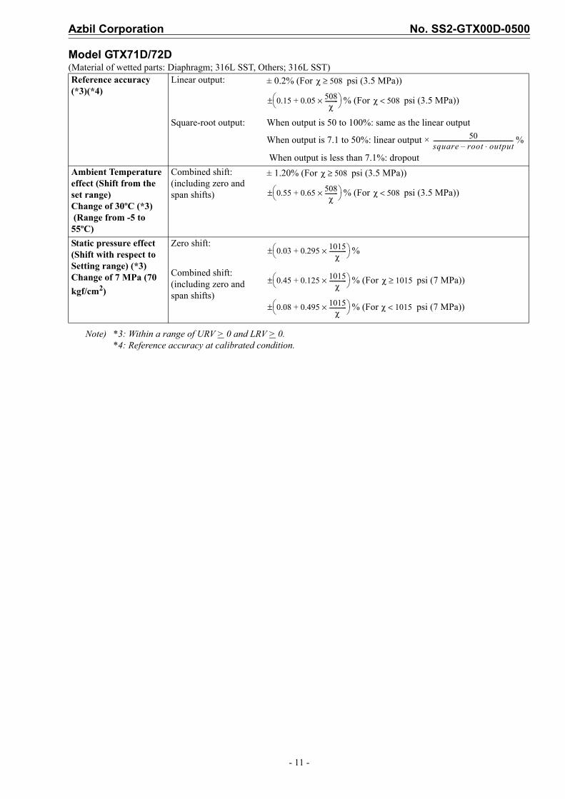
Model GTX71D/72D(Material of wetted parts: Diaphragm; 316L SST, Others; 316L SST)
Note) *3: Within a range of URV > 0 and LRV > 0.*4: Reference accuracy at calibrated condition.
Reference accuracy (*3)(*4)
Linear output: ± 0.2% (For psi (3.5 MPa))
% (For psi (3.5 MPa))
Square-root output: When output is 50 to 100%: same as the linear output
When output is 7.1 to 50%: linear output × %
When output is less than 7.1%: dropout
Ambient Temperature effect (Shift from the set range) Change of 30ºC (*3) (Range from -5 to 55ºC)
Combined shift: (including zero and span shifts)
± 1.20% (For psi (3.5 MPa))
% (For psi (3.5 MPa))
Static pressure effect(Shift with respect to Setting range) (*3)Change of 7 MPa (70
kgf/cm2)
Zero shift:%
Combined shift: (including zero and span shifts)
% (For psi (7 MPa))
% (For psi (7 MPa))
χ 508≥
0.15 0.05 508χ
---------×+ ± χ 508<
50square root– output⋅--------------------------------------------------------
χ 508≥
0.55 0.65 508χ
---------×+ ± χ 508<
0.03 0.295 1015χ
------------×+ ±
0.45 0.125 1015χ
------------×+ ± χ 1015≥
0.08 0.495 1015χ
------------×+ ± χ 1015<
No. SS2-GTX00D-0500 Azbil Corporation
- 12 -
MODEL SELECTION
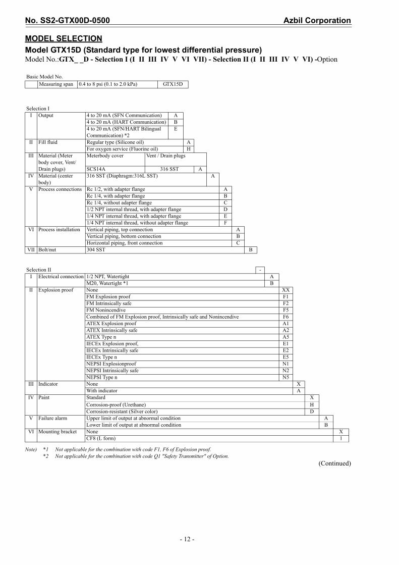
Model GTX15D (Standard type for lowest differential pressure)Model No.:GTX_ _D - Selection I (I II III IV V VI VII) - Selection II (I II III IV V VI) -Option
Note) *1 Not applicable for the combination with code F1, F6 of Explosion proof.*2 Not applicable for the combination with code Q1 "Safety Transmitter" of Option.
(Continued)
Basic Model No.Measuring span 0.4 to 8 psi (0.1 to 2.0 kPa) GTX15D
Selection II Output 4 to 20 mA (SFN Communication) A
4 to 20 mA (HART Communication) B4 to 20 mA (SFN/HART Bilingual Communication) *2
E
II Fill fluid Regular type (Silicone oil) AFor oxygen service (Fluorine oil) H
III Material (Meter body cover, Vent/Drain plugs)
Meterbody cover Vent / Drain plugs
SCS14A 316 SST AIV Material (center
body)316 SST (Diaphragm:316L SST) A
V Process connections Rc 1/2, with adapter flange ARc 1/4, with adapter flange BRc 1/4, without adapter flange C1/2 NPT internal thread, with adapter flange D1/4 NPT internal thread, with adapter flange E1/4 NPT internal thread, without adapter flange F
VI Process installation Vertical piping, top connection AVertical piping, bottom connection BHorizontal piping, front connection C
VII Bolt/nut 304 SST B
Selection II -I Electrical connection 1/2 NPT, Watertight A
M20, Watertight *1 BII Explosion proof None XX
FM Explosion proof F1FM Intrinsically safe F2FM Nonincendive F5Combined of FM Explosion proof, Intrinsically safe and Nonincendive F6ATEX Explosion proof A1ATEX Intrinsically safe A2ATEX Type n A5IECEx Explosion proof, E1IECEx Intrinsically safe E2IECEx Type n E5NEPSI Explosionproof N1NEPSI Intrinsically safe N2NEPSI Type n N5
III Indicator None XWith indicator A
IV Paint Standard XCorrosion-proof (Urethane) HCorrosion-resistant (Silver color) D
V Failure alarm Upper limit of output at abnormal condition ALower limit of output at abnormal condition B
VI Mounting bracket None XCF8 (L form) 1

Azbil Corporation No. SS2-GTX00D-0500
- 13 -
(Continued from previous page)
Model No.:GTX_ _D - Selection I (I II III IV V VI VII) - Selection II (I II III IV V VI) - Option
Note) *4 No need to select when Fill Fluid code H, or J is selected.*5 Not applicable for the combination with code A2,or Q7 of Option. *6 Not applicable for the combination with code A, or B of Process installation.*7 Not applicable for the combination with code F1, F6 of Explosion proof.*8 Not applicable for any Explosion proof. Please select code XX “None” of Explosion proof.*9 Applicable for “ASTM B575”, code B of Material (center body).*10 Not applicable for the combination with code B “M20, Watertight” electrical connection.*11 Not applicable for the combination with code X “None” of Indicator. Please select “With indicator”.*12 Not applicable for the combination with code D "Digital output (DE communication)" of output.*13 Not applicable for the combination with code F2, F5, F6, N2, N5, E2, E5, A2 and A5 of Explosion proof.
Option -No options XXAdapter flange for corrosion-resistant application (316L SST or Tantalum for the wetted parts of centerbody) A1With external Zero/Span adjustment *11 *12 A2One elbow (left) *6 *7 *10 G1One elbow (right) *6 *7 *10 G22 elbows *6 *8 *10 G3Long vent/drain plugs G4Side vent/drain top *6 G6Side vent/drain bottom *6 G7Oil and water free finish K1Oil free finish *4 K3Au Plating Diaphragm L1Safety Transmitter *5 *12 Q1NAMUR NE43 Compliant Output Signal Limits:3.8 to 20.5mA (Output 21.6mA/selected upper limit, 3.6mA/selected lower limit)*12
Q2
Alarm Output (contact output) *13 Q7Custom calibration R1Test report T1Mill certificate T2Traceability certificate T4NACE certificate *9 T5Non SI Unit W1
No. SS2-GTX00D-0500 Azbil Corporation
- 14 -
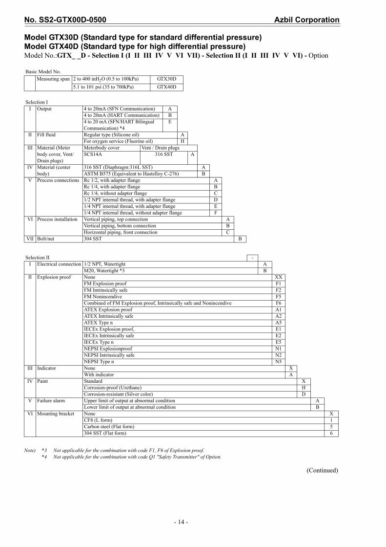
Model GTX30D (Standard type for standard differential pressure) Model GTX40D (Standard type for high differential pressure) Model No.:GTX_ _D - Selection I (I II III IV V VI VII) - Selection II (I II III IV V VI) - Option
Note) *3 Not applicable for the combination with code F1, F6 of Explosion proof.*4 Not applicable for the combination with code Q1 "Safety Transmitter" of Option.
(Continued)
Basic Model No.Measuring span 2 to 400 inH2O (0.5 to 100kPa) GTX30D
5.1 to 101 psi (35 to 700kPa) GTX40D
Selection II Output 4 to 20mA (SFN Communication) A
4 to 20mA (HART Communication) B4 to 20 mA (SFN/HART Bilingual Communication) *4
E
II Fill fluid Regular type (Silicone oil) AFor oxygen service (Fluorine oil) H
III Material (Meter body cover, Vent/Drain plugs)
Meterbody cover Vent / Drain plugsSCS14A 316 SST A
IV Material (center body)
316 SST (Diaphragm:316L SST) AASTM B575 (Equivalent to Hastelloy C-276) B
V Process connections Rc 1/2, with adapter flange ARc 1/4, with adapter flange BRc 1/4, without adapter flange C1/2 NPT internal thread, with adapter flange D1/4 NPT internal thread, with adapter flange E1/4 NPT internal thread, without adapter flange F
VI Process installation Vertical piping, top connection AVertical piping, bottom connection BHorizontal piping, front connection C
VII Bolt/nut 304 SST B
Selection II -I Electrical connection 1/2 NPT, Watertight A
M20, Watertight *3 BII Explosion proof None XX
FM Explosion proof F1FM Intrinsically safe F2FM Nonincendive F5Combined of FM Explosion proof, Intrinsically safe and Nonincendive F6ATEX Explosion proof A1ATEX Intrinsically safe A2ATEX Type n A5IECEx Explosion proof, E1IECEx Intrinsically safe E2IECEx Type n E5NEPSI Explosionproof N1NEPSI Intrinsically safe N2NEPSI Type n N5
III Indicator None XWith indicator A
IV Paint Standard XCorrosion-proof (Urethane) HCorrosion-resistant (Silver color) D
V Failure alarm Upper limit of output at abnormal condition ALower limit of output at abnormal condition B
VI Mounting bracket None XCF8 (L form) 1Carbon steel (Flat form) 5304 SST (Flat form) 6

Azbil Corporation No. SS2-GTX00D-0500
- 15 -
(Continued from previous page)
Model No.:GTX_ _D - Selection I (I II III IV V VI VII) - Selection II (I II III IV V VI) - Option
Note) *4 No need to select when Fill Fluid code H, or J is selected.*5 Not applicable for the combination with code A2,or Q7 of Option. *6 Not applicable for the combination with code A, or B of Process installation.*7 Not applicable for the combination with code F1, F6 of Explosion proof.*8 Not applicable for any Explosion proof. Please select code XX “None” of Explosion proof.*9 Applicable for “ASTM B575”, code B of Material (center body).*10 Not applicable for the combination with code B “M20, Watertight” electrical connection.*11 Not applicable for the combination with code X “None” of Indicator. Please select “With indicator”.*12 Not applicable for the combination with code D "Digital output (DE communication)" of output.*13 Not applicable for the combination with code F2, F5, F6, N2, N5, E2, E5, A2 and A5 of Explosion proof.
Option -No options XXAdapter flange for corrosion-resistant application (316L SST or Tantalum for the wetted parts of centerbody) A1With external Zero/Span adjustment *11 *12 A2One elbow (left) *6 *7 *10 G1One elbow (right) *6 *7 *10 G22 elbows *6 *8 *10 G3Long vent/drain plugs G4Side vent/drain top *6 G6Side vent/drain bottom *6 G7Oil and water free finish K1Oil free finish *4 K3Au Plating Diaphragm L1Safety Transmitter *5 *12 Q1NAMUR NE43 Compliant Output Signal Limits:3.8 to 20.5mA (Output 21.6mA/selected upper limit, 3.6mA/selected lower limit) *12
Q2
Alarm Output (contact output) *13 Q7Custom calibration R1Test report T1Mill certificate T2Traceability certificate T4NACE certificate *9 T5Non SI Unit W1
No. SS2-GTX00D-0500 Azbil Corporation
- 16 -
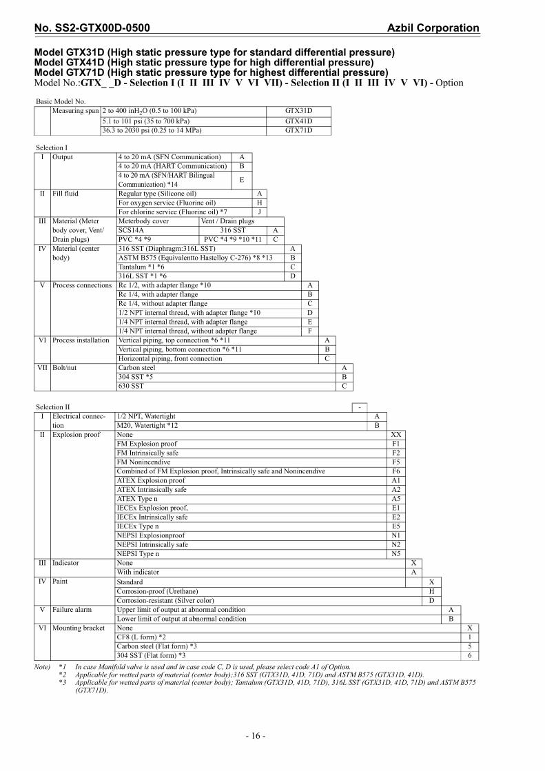
Model GTX31D (High static pressure type for standard differential pressure)Model GTX41D (High static pressure type for high differential pressure)Model GTX71D (High static pressure type for highest differential pressure)Model No.:GTX_ _D - Selection I (I II III IV V VI VII) - Selection II (I II III IV V VI) - Option
Note) *1 In case Manifold valve is used and in case code C, D is used, please select code A1 of Option.*2 Applicable for wetted parts of material (center body);316 SST (GTX31D, 41D, 71D) and ASTM B575 (GTX31D, 41D).*3 Applicable for wetted parts of material (center body); Tantalum (GTX31D, 41D, 71D), 316L SST (GTX31D, 41D, 71D) and ASTM B575
(GTX71D).
Basic Model No.Measuring span 2 to 400 inH2O (0.5 to 100 kPa) GTX31D
5.1 to 101 psi (35 to 700 kPa) GTX41D36.3 to 2030 psi (0.25 to 14 MPa) GTX71D
Selection II Output 4 to 20 mA (SFN Communication) A
4 to 20 mA (HART Communication) B4 to 20 mA (SFN/HART Bilingual Communication) *14
E
II Fill fluid Regular type (Silicone oil) AFor oxygen service (Fluorine oil) HFor chlorine service (Fluorine oil) *7 J
III Material (Meter body cover, Vent/Drain plugs)
Meterbody cover Vent / Drain plugsSCS14A 316 SST APVC *4 *9 PVC *4 *9 *10 *11 C
IV Material (center body)
316 SST (Diaphragm:316L SST) AASTM B575 (Equivalentto Hastelloy C-276) *8 *13 BTantalum *1 *6 C316L SST *1 *6 D
V Process connections Rc 1/2, with adapter flange *10 ARc 1/4, with adapter flange BRc 1/4, without adapter flange C1/2 NPT internal thread, with adapter flange *10 D1/4 NPT internal thread, with adapter flange E1/4 NPT internal thread, without adapter flange F
VI Process installation Vertical piping, top connection *6 *11 AVertical piping, bottom connection *6 *11 BHorizontal piping, front connection C
VII Bolt/nut Carbon steel A304 SST *5 B630 SST C
Selection II -I Electrical connec-
tion1/2 NPT, Watertight AM20, Watertight *12 B
II Explosion proof None XXFM Explosion proof F1FM Intrinsically safe F2FM Nonincendive F5Combined of FM Explosion proof, Intrinsically safe and Nonincendive F6ATEX Explosion proof A1ATEX Intrinsically safe A2ATEX Type n A5IECEx Explosion proof, E1IECEx Intrinsically safe E2IECEx Type n E5NEPSI Explosionproof N1NEPSI Intrinsically safe N2NEPSI Type n N5
III Indicator None XWith indicator A
IV Paint Standard XCorrosion-proof (Urethane) HCorrosion-resistant (Silver color) D
V Failure alarm Upper limit of output at abnormal condition ALower limit of output at abnormal condition B
VI Mounting bracket None XCF8 (L form) *2 1Carbon steel (Flat form) *3 5304 SST (Flat form) *3 6
Azbil Corporation No. SS2-GTX00D-0500
- 17 -
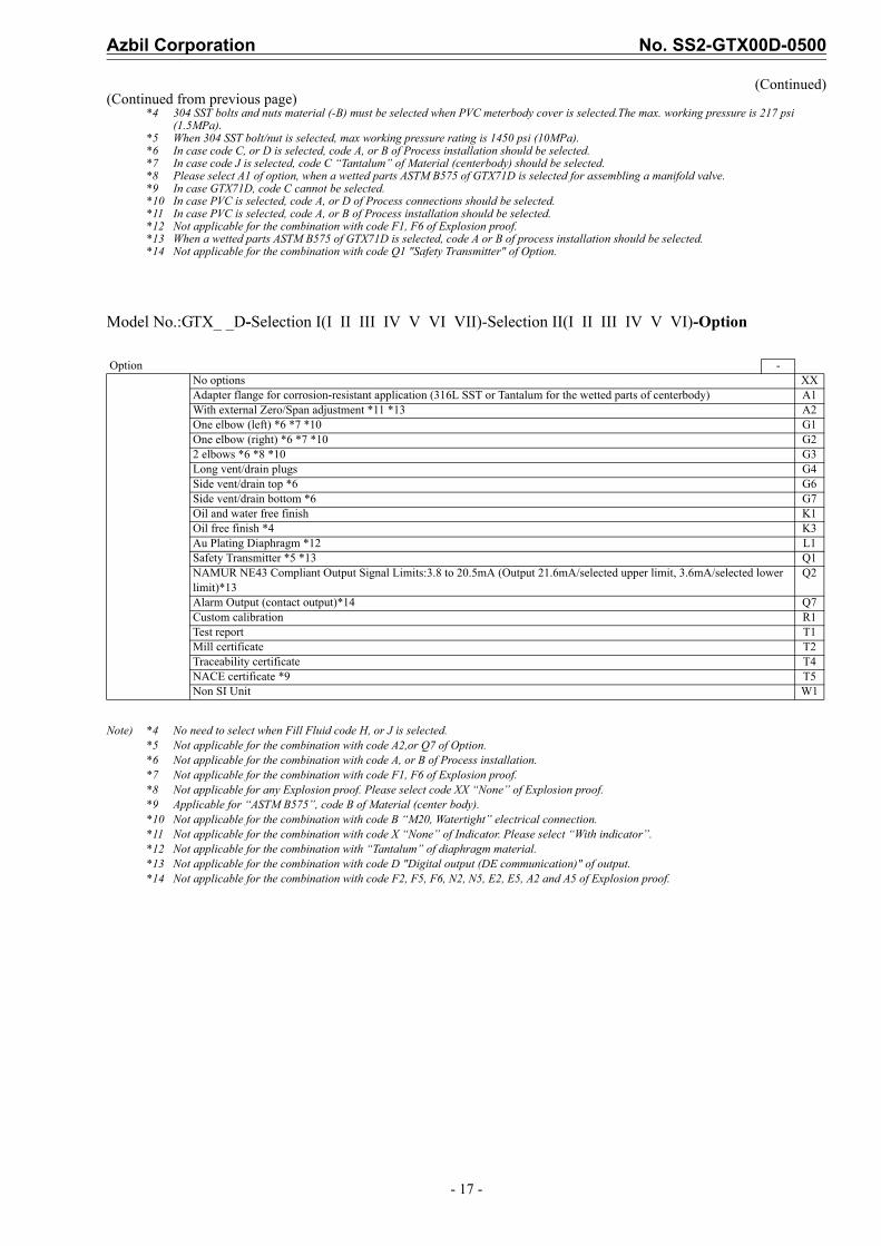
(Continued)(Continued from previous page)
*4 304 SST bolts and nuts material (-B) must be selected when PVC meterbody cover is selected.The max. working pressure is 217 psi (1.5MPa).
*5 When 304 SST bolt/nut is selected, max working pressure rating is 1450 psi (10MPa).*6 In case code C, or D is selected, code A, or B of Process installation should be selected.*7 In case code J is selected, code C “Tantalum” of Material (centerbody) should be selected.*8 Please select A1 of option, when a wetted parts ASTM B575 of GTX71D is selected for assembling a manifold valve.*9 In case GTX71D, code C cannot be selected.*10 In case PVC is selected, code A, or D of Process connections should be selected.*11 In case PVC is selected, code A, or B of Process installation should be selected.*12 Not applicable for the combination with code F1, F6 of Explosion proof.*13 When a wetted parts ASTM B575 of GTX71D is selected, code A or B of process installation should be selected.*14 Not applicable for the combination with code Q1 "Safety Transmitter" of Option.
Model No.:GTX_ _D-Selection I(I II III IV V VI VII)-Selection II(I II III IV V VI)-Option
Note) *4 No need to select when Fill Fluid code H, or J is selected.*5 Not applicable for the combination with code A2,or Q7 of Option. *6 Not applicable for the combination with code A, or B of Process installation.*7 Not applicable for the combination with code F1, F6 of Explosion proof.*8 Not applicable for any Explosion proof. Please select code XX “None” of Explosion proof.*9 Applicable for “ASTM B575”, code B of Material (center body).*10 Not applicable for the combination with code B “M20, Watertight” electrical connection.*11 Not applicable for the combination with code X “None” of Indicator. Please select “With indicator”.*12 Not applicable for the combination with “Tantalum” of diaphragm material.*13 Not applicable for the combination with code D "Digital output (DE communication)" of output.*14 Not applicable for the combination with code F2, F5, F6, N2, N5, E2, E5, A2 and A5 of Explosion proof.
Option -No options XXAdapter flange for corrosion-resistant application (316L SST or Tantalum for the wetted parts of centerbody) A1With external Zero/Span adjustment *11 *13 A2One elbow (left) *6 *7 *10 G1One elbow (right) *6 *7 *10 G22 elbows *6 *8 *10 G3Long vent/drain plugs G4Side vent/drain top *6 G6Side vent/drain bottom *6 G7Oil and water free finish K1Oil free finish *4 K3Au Plating Diaphragm *12 L1Safety Transmitter *5 *13 Q1NAMUR NE43 Compliant Output Signal Limits:3.8 to 20.5mA (Output 21.6mA/selected upper limit, 3.6mA/selected lower limit)*13
Q2
Alarm Output (contact output)*14 Q7Custom calibration R1Test report T1Mill certificate T2Traceability certificate T4NACE certificate *9 T5Non SI Unit W1
No. SS2-GTX00D-0500 Azbil Corporation
- 18 -
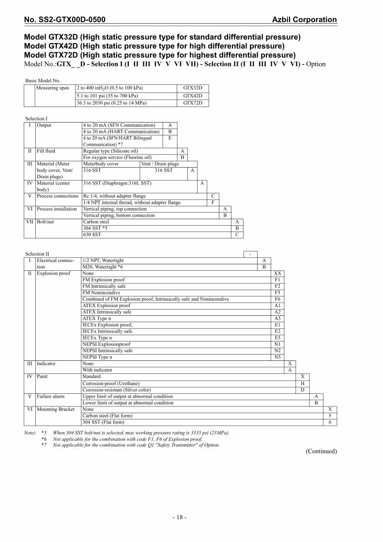
Model GTX32D (High static pressure type for standard differential pressure)Model GTX42D (High static pressure type for high differential pressure)Model GTX72D (High static pressure type for highest differential pressure)Model No.:GTX_ _D - Selection I (I II III IV V VI VII) - Selection II (I II III IV V VI) - Option
Note) *5 When 304 SST bolt/nut is selected, max working pressure rating is 3335 psi (23MPa).*6 Not applicable for the combination with code F1, F6 of Explosion proof.*7 Not applicable for the combination with code Q1 "Safety Transmitter" of Option.
(Continued)
Basic Model No.Measuring span 2 to 400 inH2O (0.5 to 100 kPa) GTX32D
5.1 to 101 psi (35 to 700 kPa) GTX42D 36.3 to 2030 psi (0.25 to 14 MPa) GTX72D
Selection II Output 4 to 20 mA (SFN Communication) A
4 to 20 mA (HART Communication) B4 to 20 mA (SFN/HART Bilingual Communication) *7
E
II Fill fluid Regular type (Silicone oil) AFor oxygen service (Fluorine oil) H
III Material (Meter body cover, Vent/Drain plugs)
Meterbody cover Vent / Drain plugs316 SST 316 SST A
IV Material (center body)
316 SST (Diaphragm:316L SST) A
V Process connections Rc 1/4, without adapter flange C1/4 NPT internal thread, without adapter flange F
VI Process installation Vertical piping, top connection AVertical piping, bottom connection B
VII Bolt/nut Carbon steel A304 SST *5 B630 SST C
Selection II -I Electrical connec-
tion1/2 NPT, Watertight AM20, Watertight *6 B
II Explosion proof None XXFM Explosion proof F1FM Intrinsically safe F2FM Nonincendive F5Combined of FM Explosion proof, Intrinsically safe and Nonincendive F6ATEX Explosion proof A1ATEX Intrinsically safe A2ATEX Type n A5IECEx Explosion proof, E1IECEx Intrinsically safe E2IECEx Type n E5NEPSI Explosionproof N1NEPSI Intrinsically safe N2NEPSI Type n N5
III Indicator None XWith indicator A
IV Paint Standard XCorrosion-proof (Urethane) HCorrosion-resistant (Silver color) D
V Failure alarm Upper limit of output at abnormal condition ALower limit of output at abnormal condition B
VI Mounting Bracket None XCarbon steel (Flat form) 5304 SST (Flat form) 6
Azbil Corporation No. SS2-GTX00D-0500
- 19 -
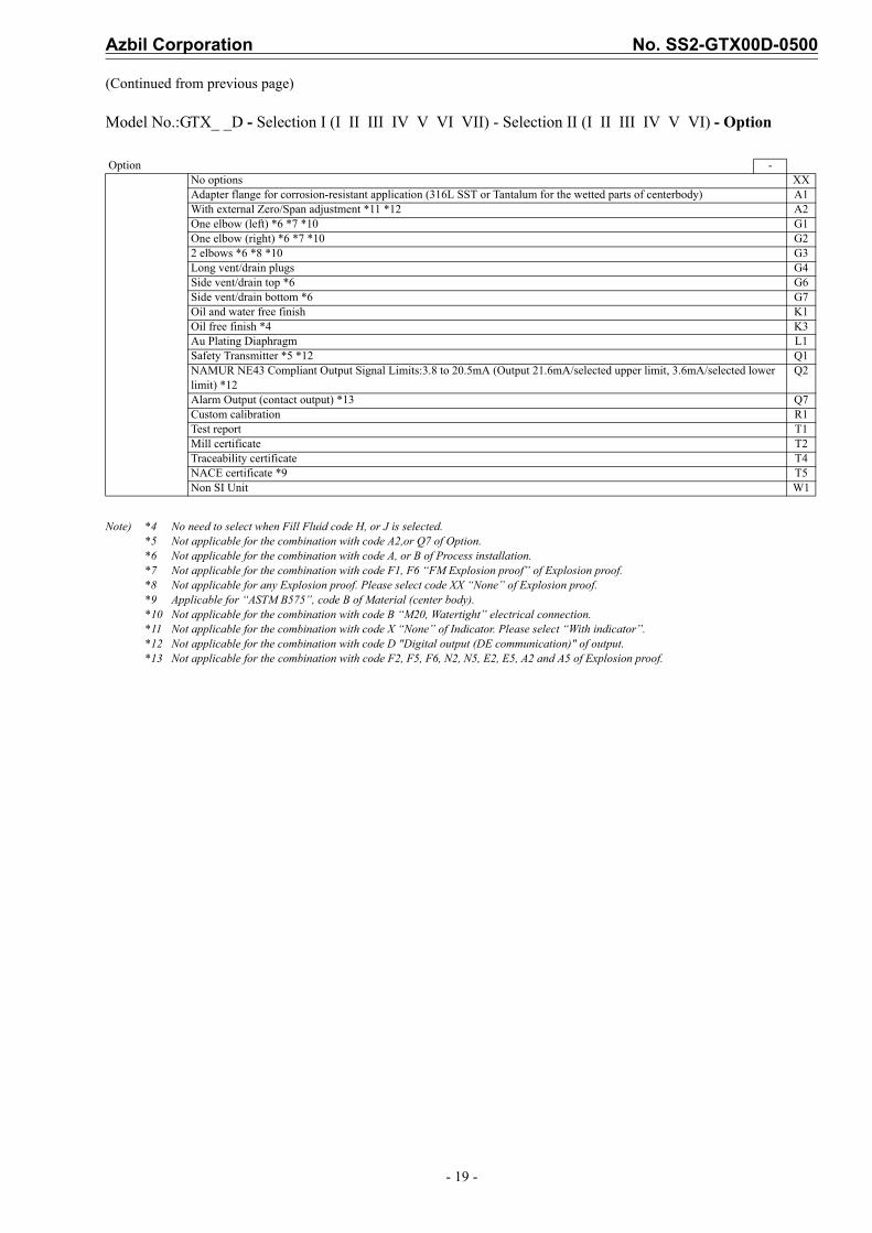
(Continued from previous page)
Model No.:GTX_ _D - Selection I (I II III IV V VI VII) - Selection II (I II III IV V VI) - Option
Note) *4 No need to select when Fill Fluid code H, or J is selected.*5 Not applicable for the combination with code A2,or Q7 of Option. *6 Not applicable for the combination with code A, or B of Process installation.*7 Not applicable for the combination with code F1, F6 “FM Explosion proof” of Explosion proof.*8 Not applicable for any Explosion proof. Please select code XX “None” of Explosion proof.*9 Applicable for “ASTM B575”, code B of Material (center body).*10 Not applicable for the combination with code B “M20, Watertight” electrical connection.*11 Not applicable for the combination with code X “None” of Indicator. Please select “With indicator”.*12 Not applicable for the combination with code D "Digital output (DE communication)" of output.*13 Not applicable for the combination with code F2, F5, F6, N2, N5, E2, E5, A2 and A5 of Explosion proof.
Option -No options XXAdapter flange for corrosion-resistant application (316L SST or Tantalum for the wetted parts of centerbody) A1With external Zero/Span adjustment *11 *12 A2One elbow (left) *6 *7 *10 G1One elbow (right) *6 *7 *10 G22 elbows *6 *8 *10 G3Long vent/drain plugs G4Side vent/drain top *6 G6Side vent/drain bottom *6 G7Oil and water free finish K1Oil free finish *4 K3Au Plating Diaphragm L1Safety Transmitter *5 *12 Q1NAMUR NE43 Compliant Output Signal Limits:3.8 to 20.5mA (Output 21.6mA/selected upper limit, 3.6mA/selected lower limit) *12
Q2
Alarm Output (contact output) *13 Q7Custom calibration R1Test report T1Mill certificate T2Traceability certificate T4NACE certificate *9 T5Non SI Unit W1
No. SS2-GTX00D-0500 Azbil Corporation
- 20 -
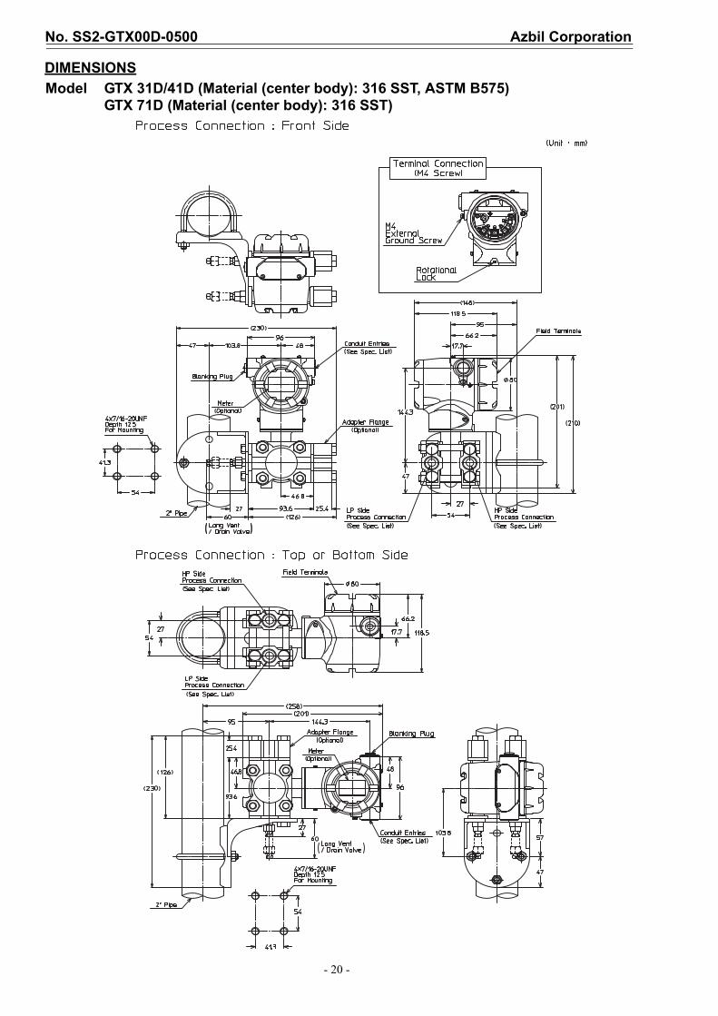
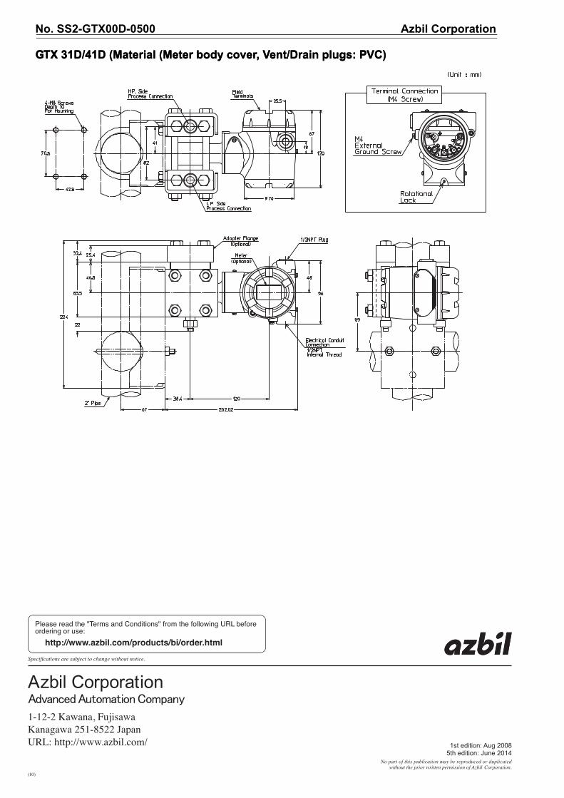
DIMENSIONS
Model GTX 31D/41D (Material (center body): 316 SST, ASTM B575)GTX 71D (Material (center body): 316 SST)
Azbil Corporation No. SS2-GTX00D-0500
- 21 -
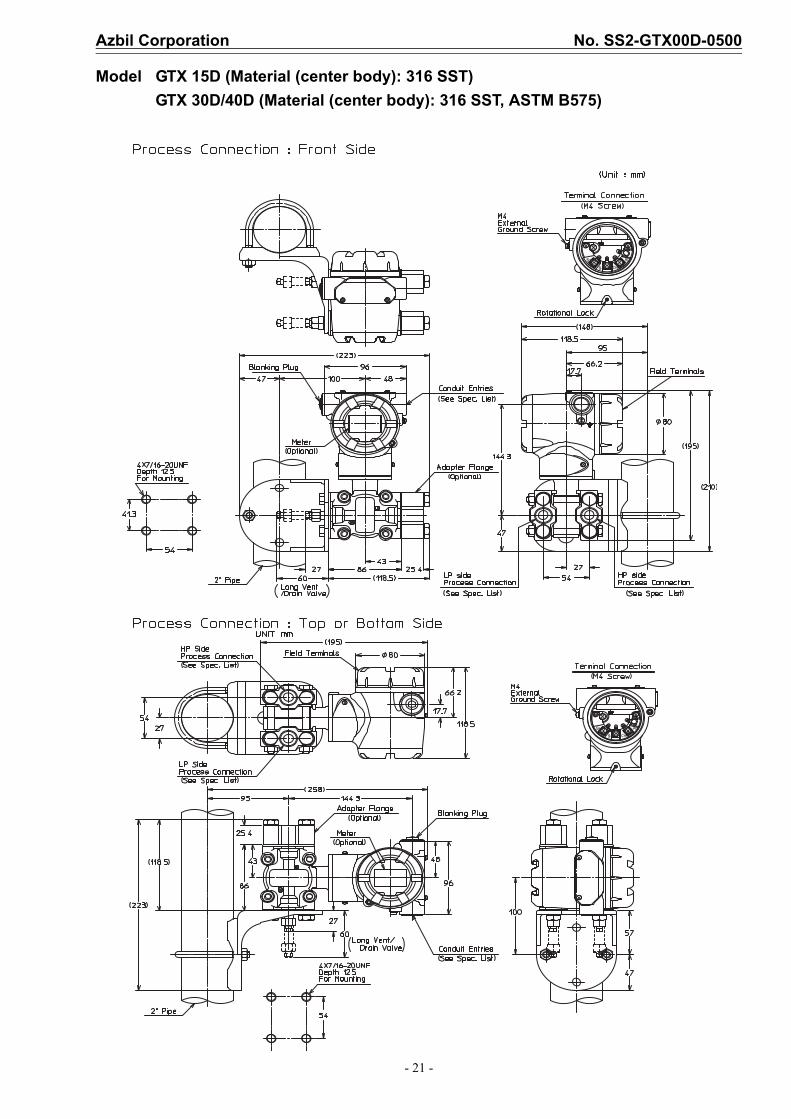
Model GTX 15D (Material (center body): 316 SST)
GTX 30D/40D (Material (center body): 316 SST, ASTM B575)
No. SS2-GTX00D-0500 Azbil Corporation
- 22 -
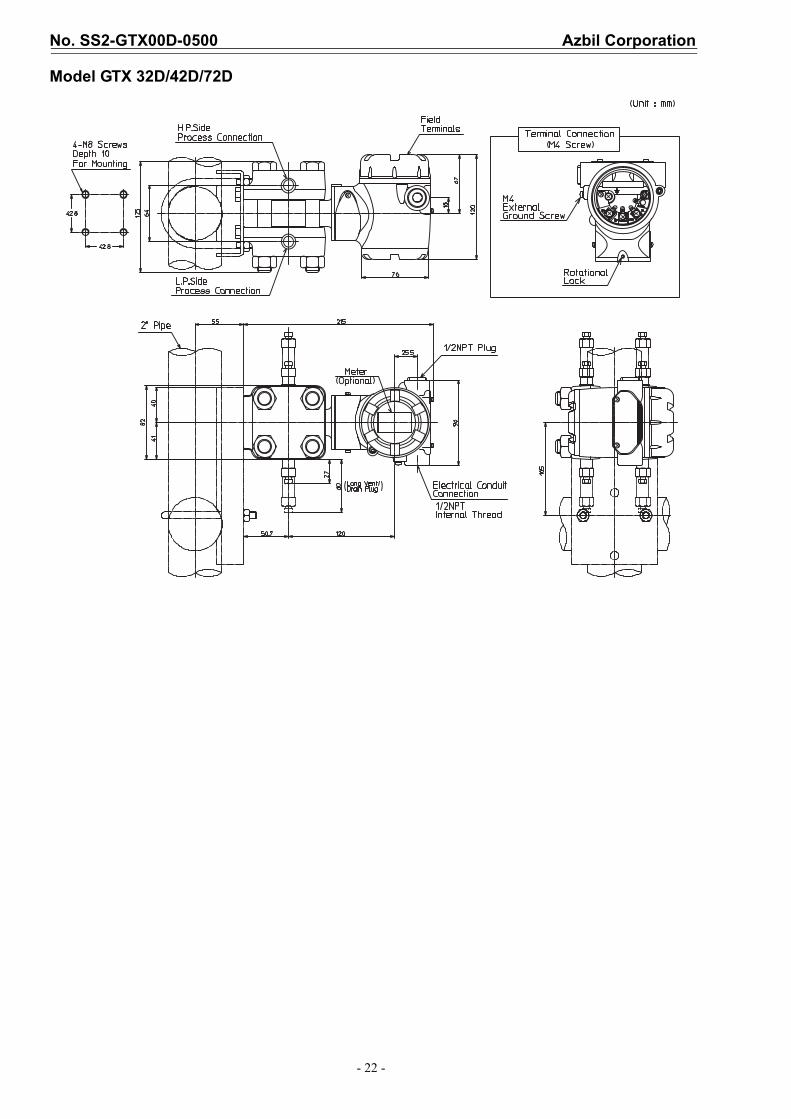
Model GTX 32D/42D/72D
Azbil Corporation No. SS2-GTX00D-0500
- 23 -
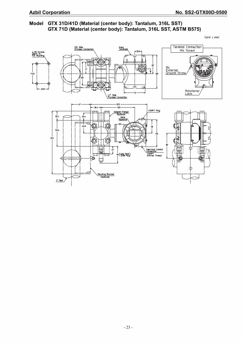
Model GTX 31D/41D (Material (center body): Tantalum, 316L SST) GTX 71D (Material (center body): Tantalum, 316L SST, ASTM B575)
No. SS2-GTX00D-0500 Azbil Corporation
- 24 -
1st edition: Aug 20085th edition: June 2014
GTX 31D/41D (Material (Meter body cover, Vent/Drain plugs: PVC)GTX 31D/41D (Material (Meter body cover, Vent/Drain plugs: PVC)