Embed Size (px)
Citation preview

Harmonic Excitation Applications of Vibratory
Systems Subha Kumpaty
ASME Milwaukee Section
Webinar 3/27/21
Introduction
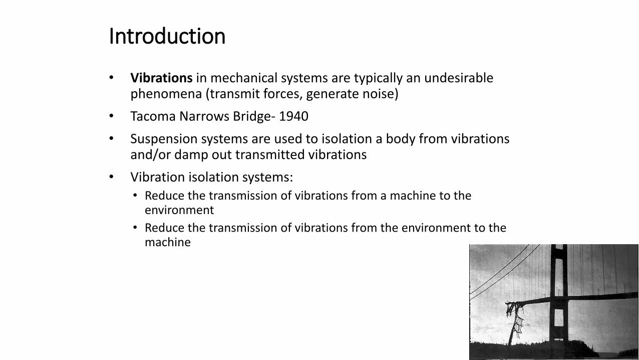
• Vibrations in mechanical systems are typically an undesirable phenomena (transmit forces, generate noise)
• Tacoma Narrows Bridge- 1940
• Suspension systems are used to isolation a body from vibrations and/or damp out transmitted vibrations
• Vibration isolation systems:• Reduce the transmission of vibrations from a machine to the
environment
• Reduce the transmission of vibrations from the environment to the machine
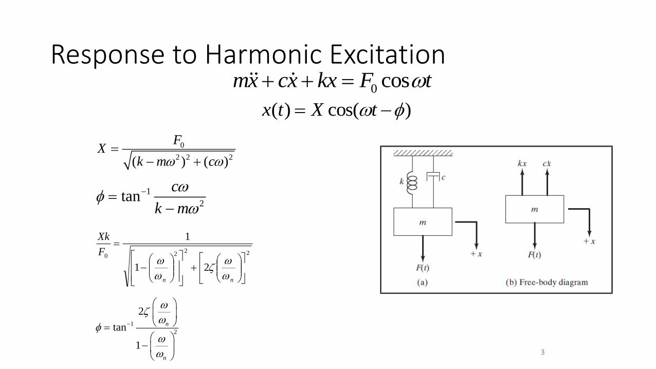
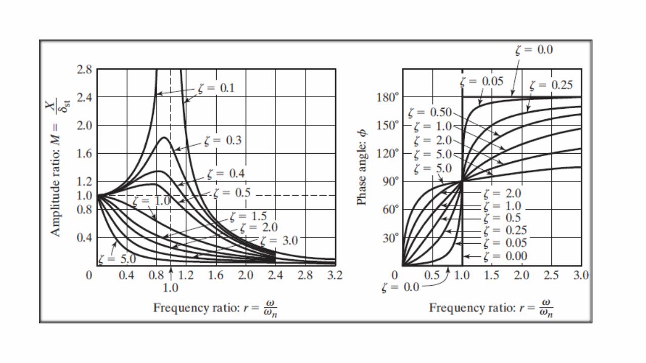
Response to Harmonic Excitation0 cosmx cx kx F t+ + =
( ) cos( )x t X t = −
0
2 2 2( ) ( )
FX
k m c =
− +
1
2tan
c
k m
−=−
2220
21
1
+
−
=
nn
F
Xk
1
2
2
tan
1
n
n
−
=
−
3
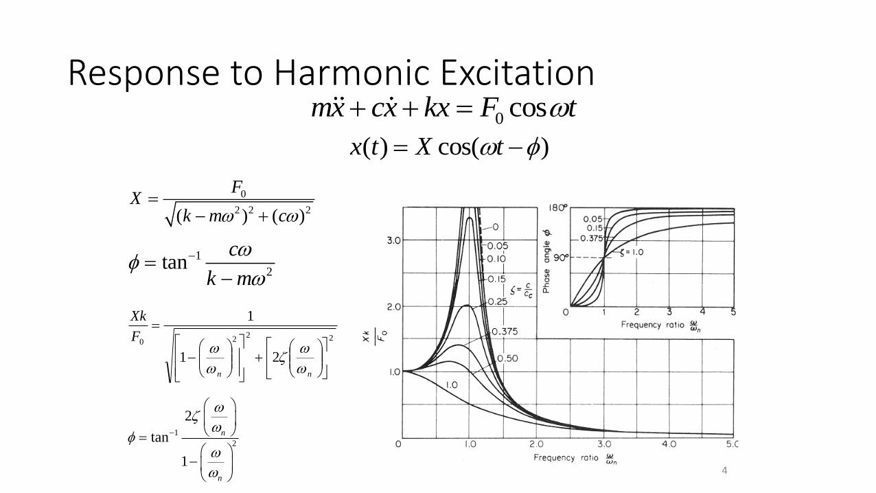
Response to Harmonic Excitation0 cosmx cx kx F t+ + =
( ) cos( )x t X t = −
0
2 2 2( ) ( )
FX
k m c =
− +
1
2tan
c
k m
−=−
2220
21
1
+
−
=
nn
F
Xk
1
2
2
tan
1
n
n
−
=
−
4
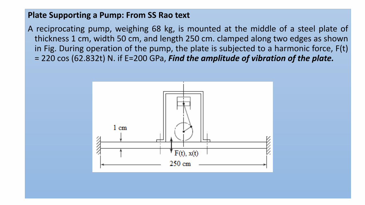
Plate Supporting a Pump: From SS Rao text
A reciprocating pump, weighing 68 kg, is mounted at the middle of a steel plate ofthickness 1 cm, width 50 cm, and length 250 cm. clamped along two edges as shownin Fig. During operation of the pump, the plate is subjected to a harmonic force, F(t)= 220 cos (62.832t) N. if E=200 GPa, Find the amplitude of vibration of the plate.
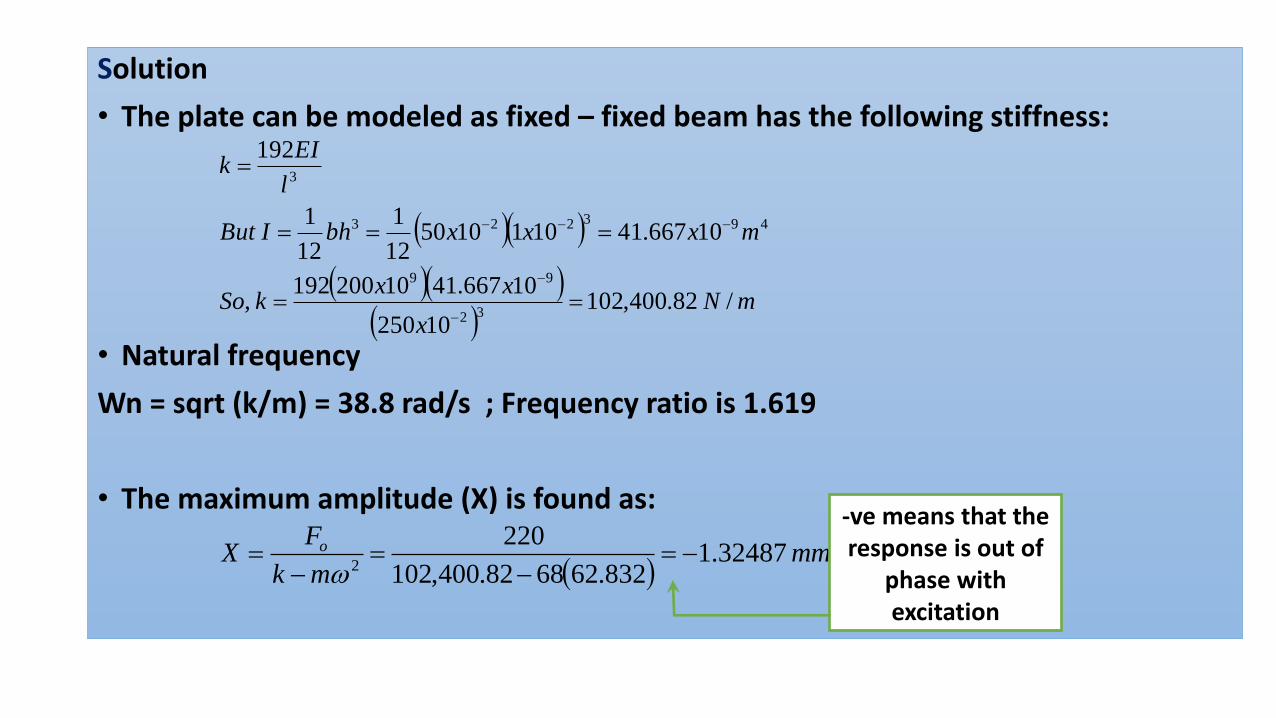
Solution
• The plate can be modeled as fixed – fixed beam has the following stiffness:
• Natural frequency
Wn = sqrt (k/m) = 38.8 rad/s ; Frequency ratio is 1.619
• The maximum amplitude (X) is found as:
( )( )
( )( )( )
mNx
xxkSo
mxxxbhIBut
l
EIk
/ 82.400,10210250
10667.4110200192 ,
10667.41101105012
1
12
1
192
32
99
493223
3
==
===
=
−
−
−−−
( )mm
mk
FX o 32487.1
832.626882.400,102
2202
−=−
=−
=
-ve means that the response is out of
phase with excitation
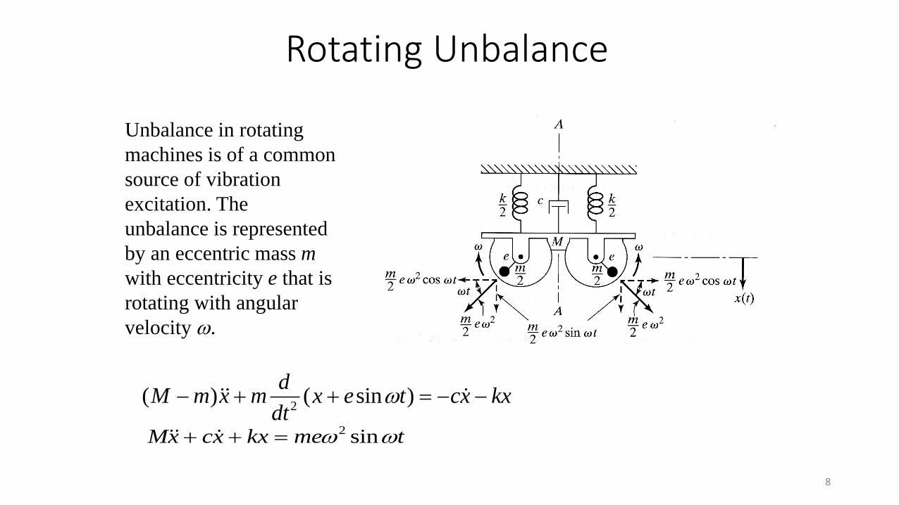
8
2( ) ( sin )
dM m x m x e t cx kx
dt− + + = − −
Unbalance in rotating
machines is of a common
source of vibration
excitation. The
unbalance is represented
by an eccentric mass m
with eccentricity e that is
rotating with angular
velocity .
2 sinMx cx kx me t + + =
Rotating Unbalance
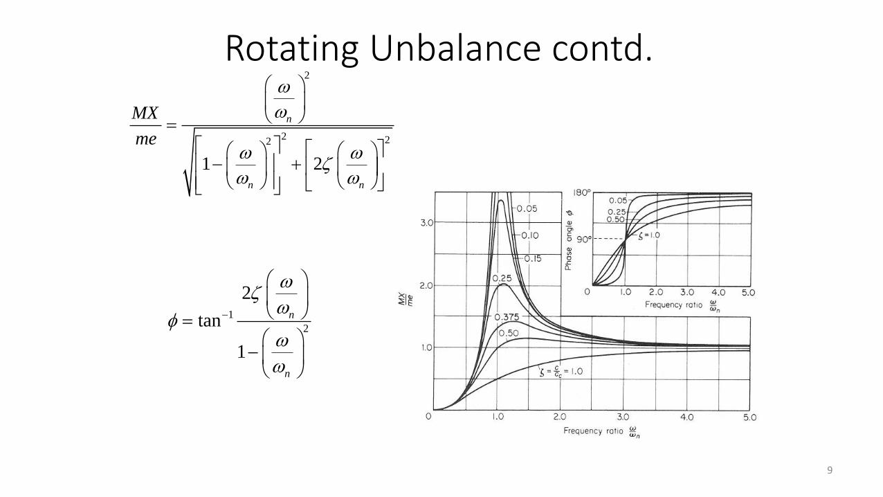
9
1
2
2
tan
1
n
n
−
=
−
2
2 22
1 2
n
n n
MX
me
=
− +
Rotating Unbalance contd.
10
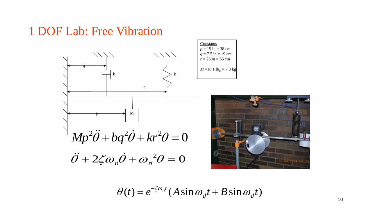
1 DOF Lab: Free Vibration
2 2 2 0Mp bq kr + + =
Mp
q
b k
r
Constants
p = 15 in = 38 cm
q = 7.5 in = 19 cm
r = 26 in = 66 cm
M =16.1 lbm = 7.3 kg
22 0n n + + =
( ) ( sin sin )nt
d dt e A t B t −
= +
11
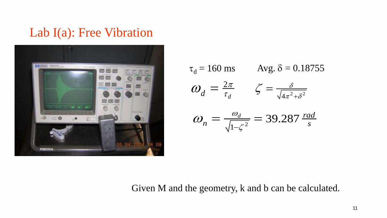
Lab I(a): Free Vibration
2
dd
=
d = 160 ms
2 24
+=
.
Avg. = 0.18755
2139.287d rad
n s
−= =
Given M and the geometry, k and b can be calculated.
12
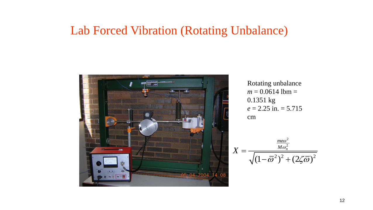
Lab Forced Vibration (Rotating Unbalance)
Rotating unbalance
m = 0.0614 lbm =
0.1351 kg
e = 2.25 in. = 5.715
cm
2
2
2 2 2(1 ) (2 )
n
me
MX
=
− +
13
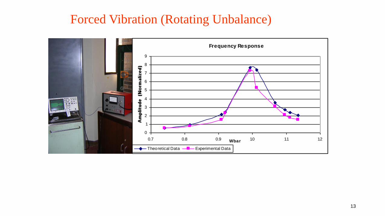
Forced Vibration (Rotating Unbalance)
Frequency Response
0
1
2
3
4
5
6
7
8
9
0.7 0.8 0.9 1.0 1.1 1.2Wbar
Theoretical Data Experimental Data
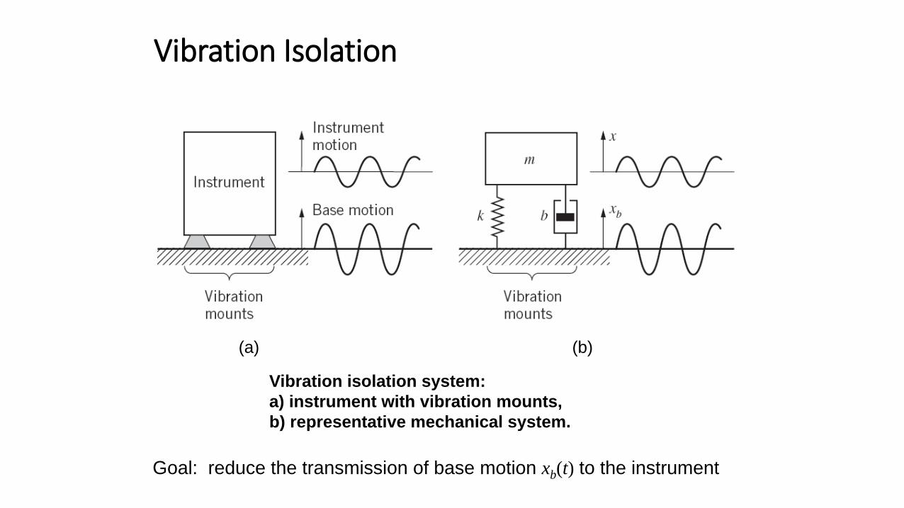
Vibration Isolation
Vibration isolation system:
a) instrument with vibration mounts,
b) representative mechanical system.
Goal: reduce the transmission of base motion xb(t) to the instrument
(a) (b)
15
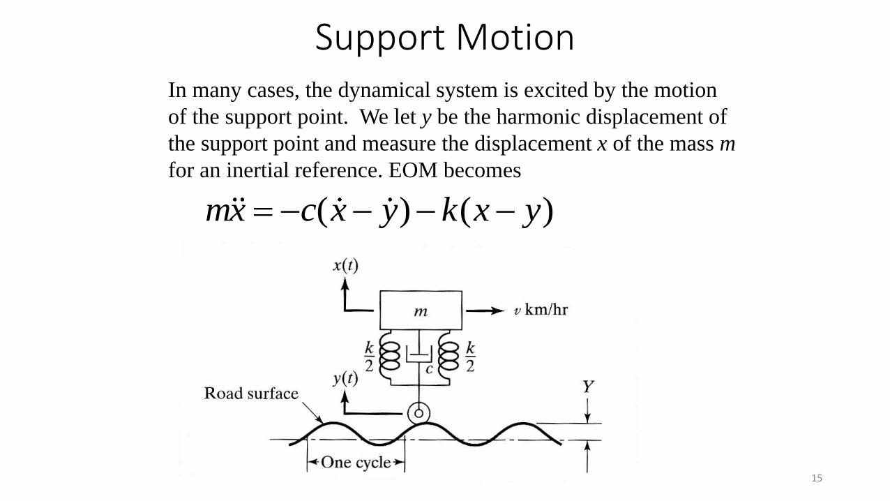
( ) ( )mx c x y k x y= − − − −
In many cases, the dynamical system is excited by the motion
of the support point. We let y be the harmonic displacement of
the support point and measure the displacement x of the mass m
for an inertial reference. EOM becomes
Support Motion
16
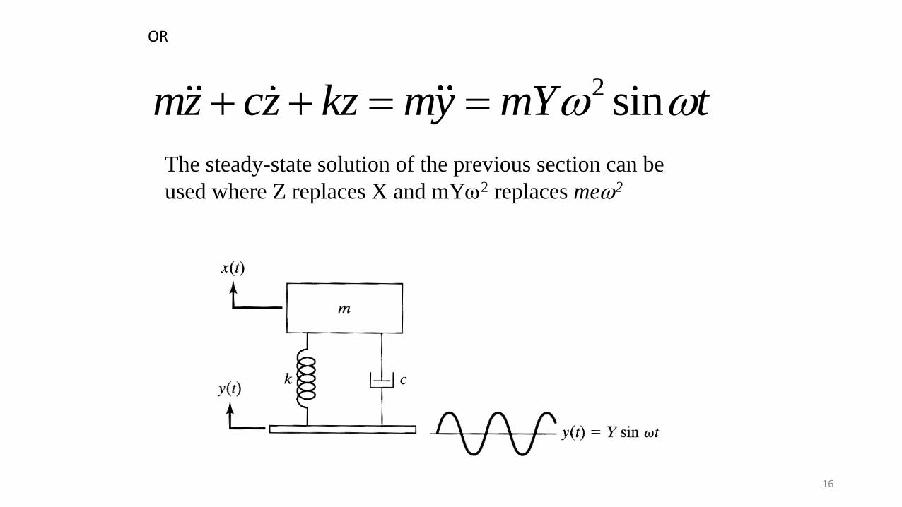
OR
2 sinmz cz kz my mY t + + = =
The steady-state solution of the previous section can be
used where Z replaces X and mY2 replaces me2
17
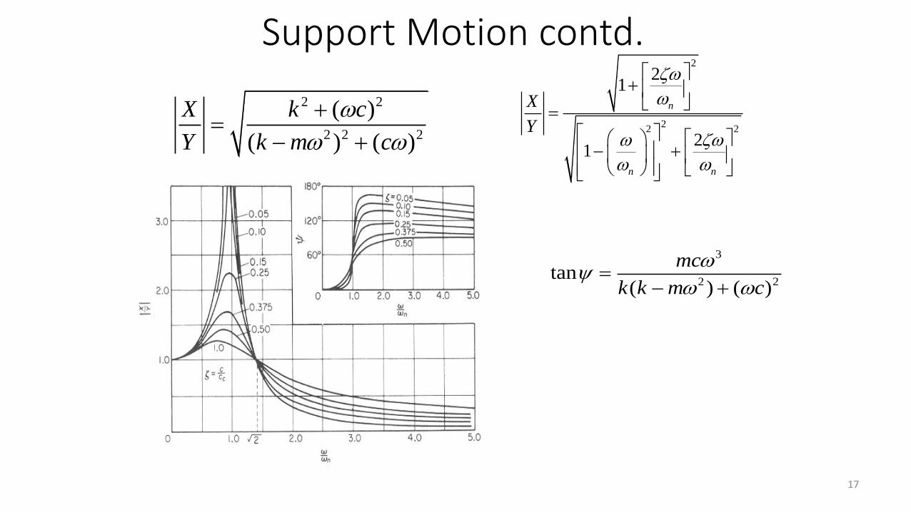
2 2
2 2 2
( )
( ) ( )
X k c
Y k m c
+=
− +
3
2 2tan
( ) ( )
mc
k k m c
=
− +
2
22 2
21
21
n
n n
X
Y
+
=
− +
Support Motion contd.
18
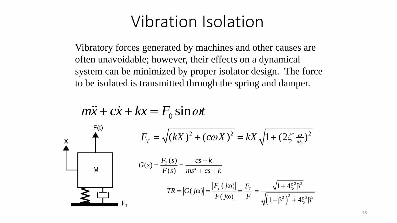
0 sinmx cx kx F t+ + =
Vibratory forces generated by machines and other causes are
often unavoidable; however, their effects on a dynamical
system can be minimized by proper isolator design. The force
to be isolated is transmitted through the spring and damper.
2 2 2( ) ( ) 1 (2 )nTF kX c X kX
= + = +
FT
Vibration Isolation
( )
2 2
22 2 2
( ω) 1 4ξ β( ω)
( ω)1 β 4ξ β
T TF j F
TR G jF j F
+= = = =
− +
2
( )( )
( )
TF s cs kG s
F s ms cs k
+= =
+ +
19
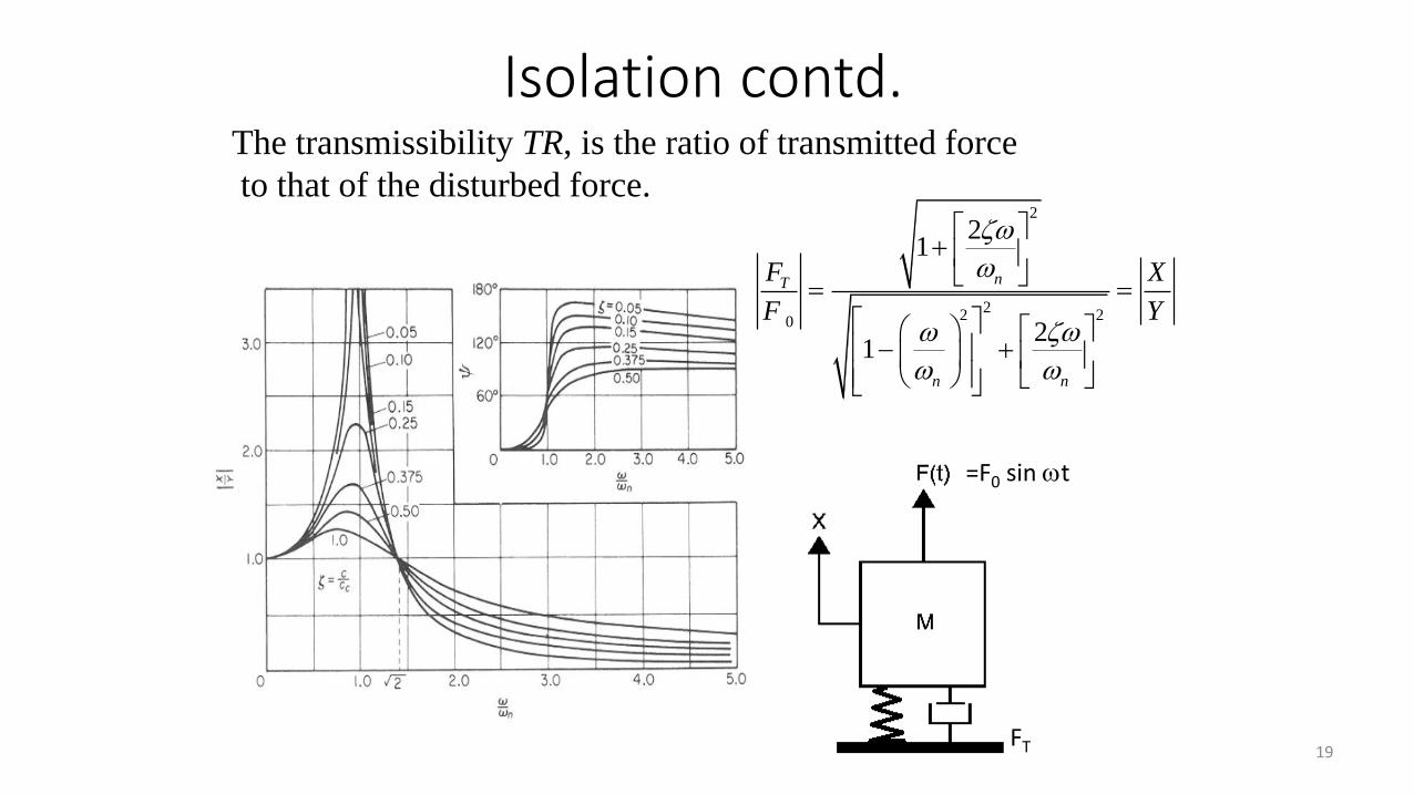
2
22 20
21
21
nT
n n
F X
F Y
+
= =
− +
The transmissibility TR, is the ratio of transmitted force
to that of the disturbed force.
=F0 sin t
FT
Isolation contd.
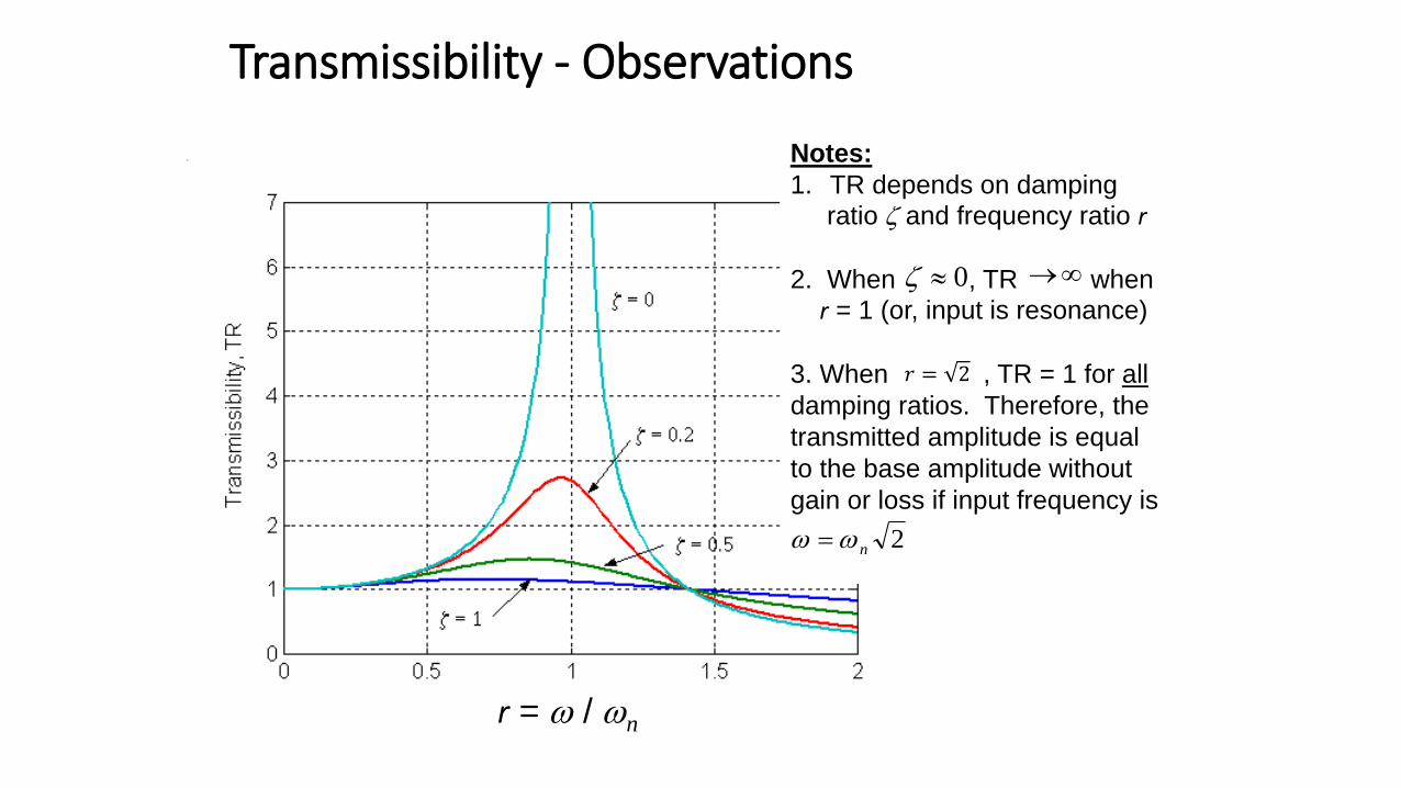
Transmissibility - Observations
r = / n
Notes:
1. TR depends on damping
ratio and frequency ratio r
2. When , TR when r = 1 (or, input is resonance)
3. When , TR = 1 for all
damping ratios. Therefore, the
transmitted amplitude is equal
to the base amplitude without
gain or loss if input frequency is
0 →
𝑟 = 2
2n =
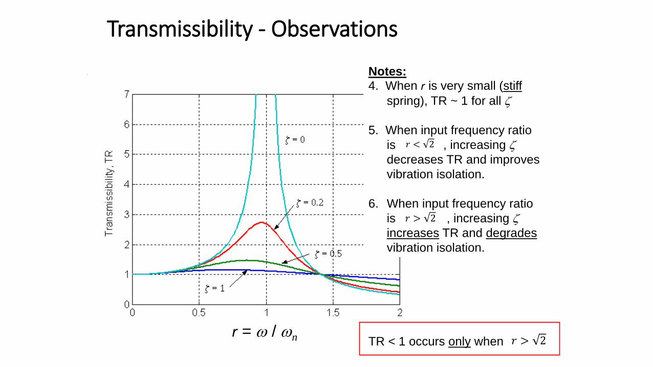
Transmissibility - Observations
r = / n
Notes:4. When r is very small (stiff
spring), TR ~ 1 for all
5. When input frequency ratio
is , increasing
decreases TR and improves
vibration isolation.
6. When input frequency ratio
is , increasing
increases TR and degrades
vibration isolation.
𝑟 < 2
𝑟 > 2
TR < 1 occurs only when 𝑟 > 2
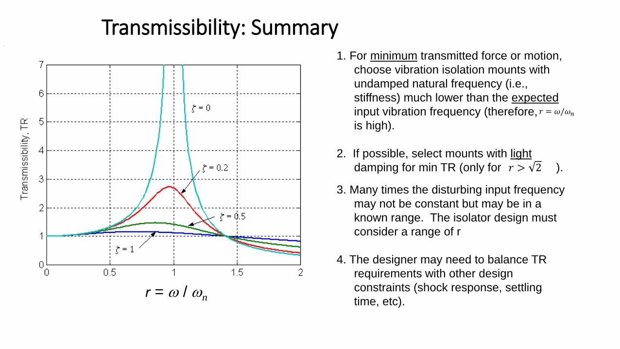
Transmissibility: Summary
r = / n
1. For minimum transmitted force or motion,
choose vibration isolation mounts with
undamped natural frequency (i.e.,
stiffness) much lower than the expected
input vibration frequency (therefore,
is high).
2. If possible, select mounts with light
damping for min TR (only for ).
𝑟 = 𝜔/𝜔𝑛
𝑟 > 2
3. Many times the disturbing input frequency
may not be constant but may be in a
known range. The isolator design must
consider a range of r
4. The designer may need to balance TR
requirements with other design
constraints (shock response, settling
time, etc).
23
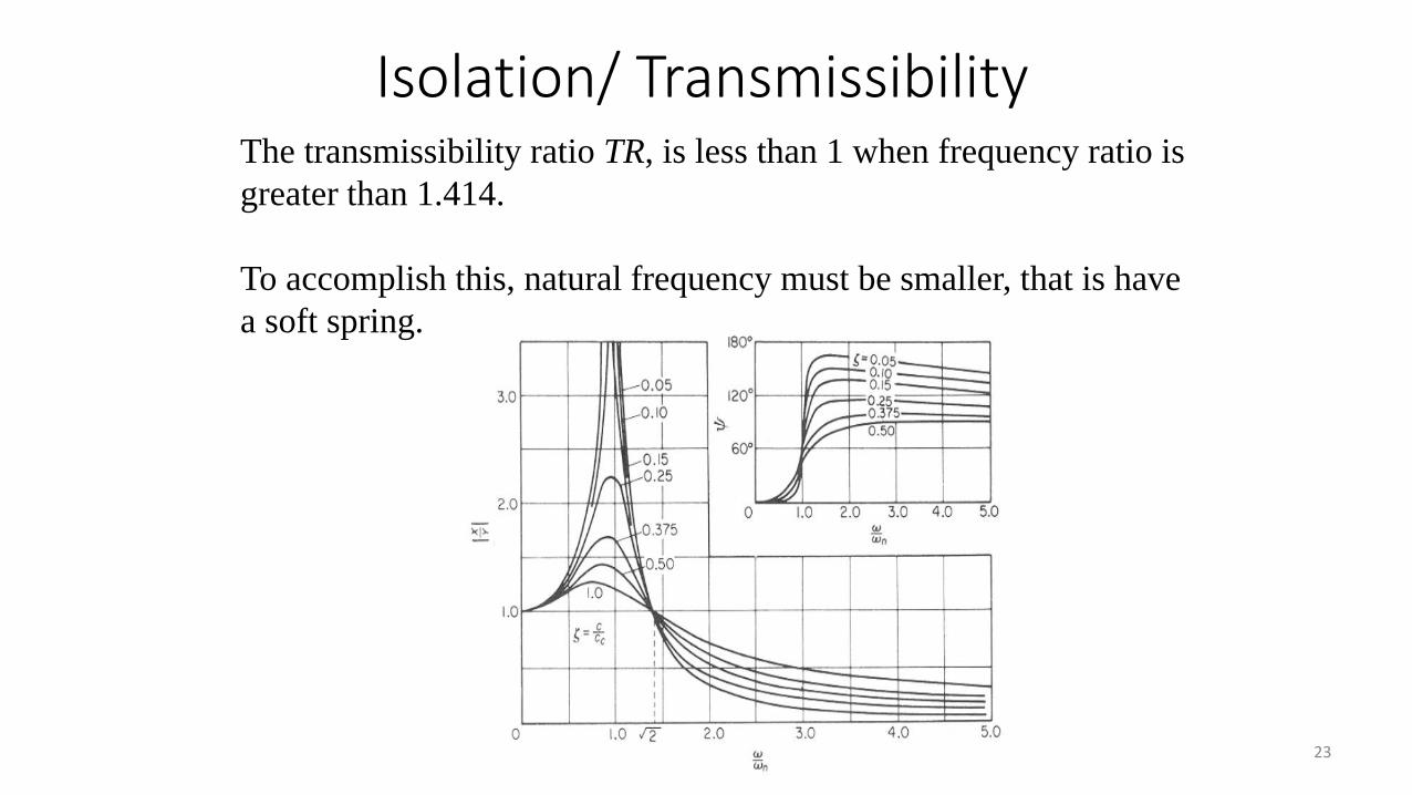
The transmissibility ratio TR, is less than 1 when frequency ratio is
greater than 1.414.
To accomplish this, natural frequency must be smaller, that is have
a soft spring.
Isolation/ Transmissibility
24
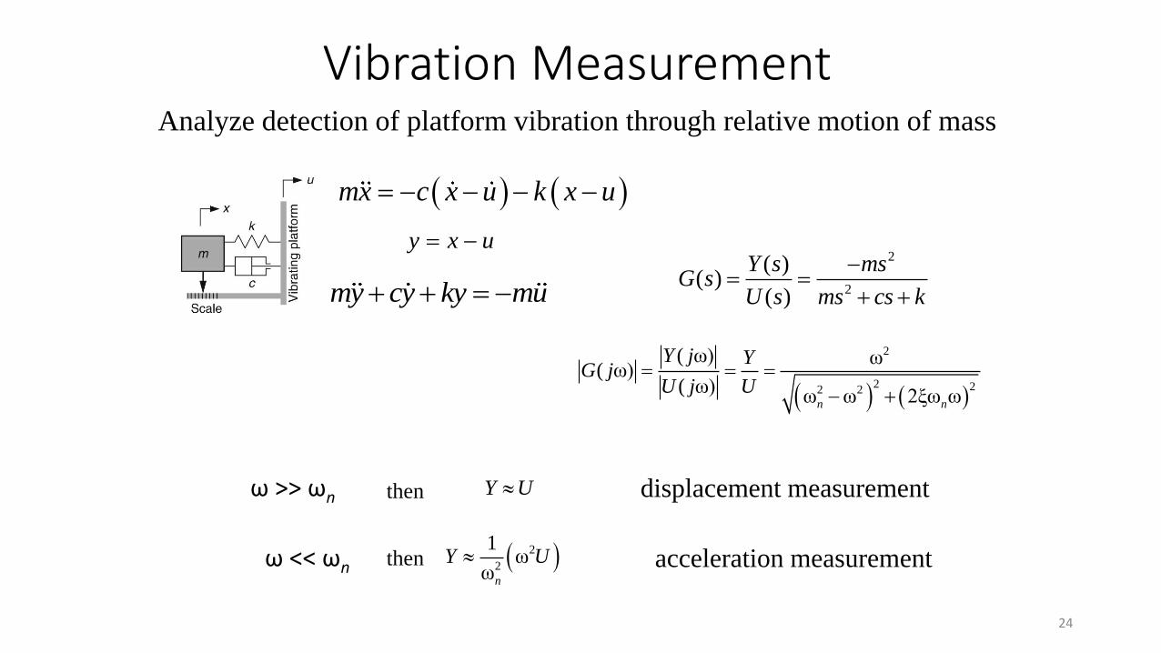
Vibration MeasurementAnalyze detection of platform vibration through relative motion of mass
( ) ( )mx c x u k x u= − − − −
y x u= −
my cy ky mu+ + = −
2
2
( )( )
( )
Y s msG s
U s ms cs k
−= =
+ +
( ) ( )
2
2 22 2
( ω) ω( ω)
( ω)ω ω 2ξω ωn n
Y j YG j
U j U= = =
− +
ω >> ωn Y U displacement measurementthen
( )2
2
1ω
ωn
Y Uω << ωn acceleration measurementthen
25
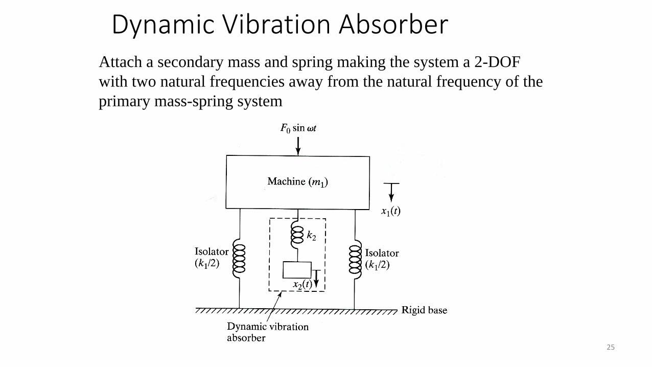
Attach a secondary mass and spring making the system a 2-DOF
with two natural frequencies away from the natural frequency of the
primary mass-spring system
Dynamic Vibration Absorber
26
27
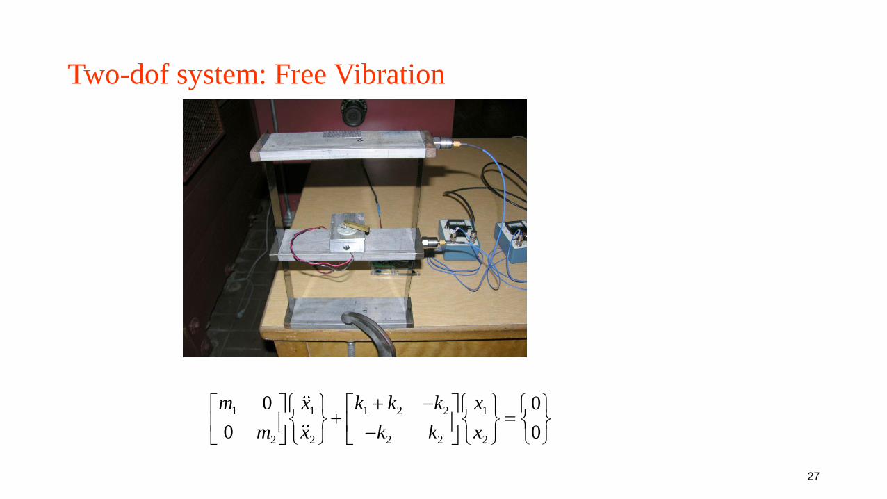
Two-dof system: Free Vibration
1 1 1 2 2 1
2 2 2 2 2
0 0
0 0
m x k k k x
m x k k x
+ − + = −
28
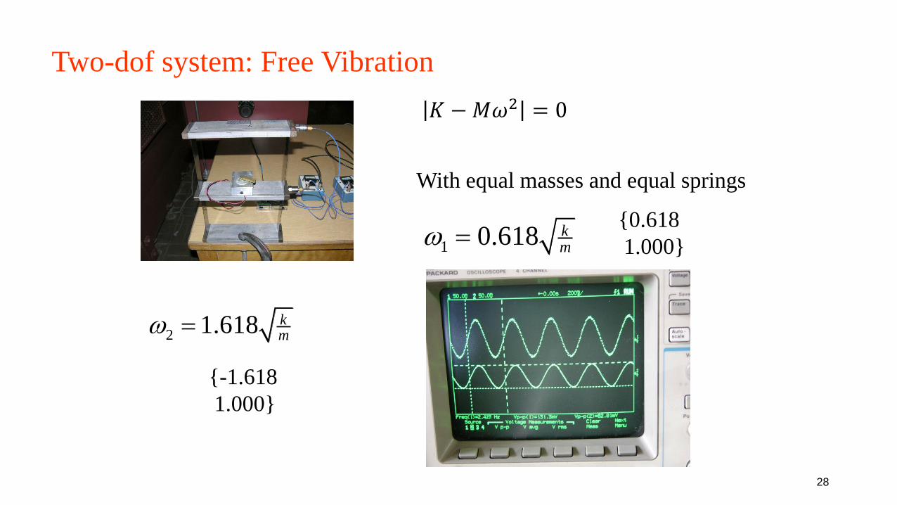
Two-dof system: Free Vibration
2 0K M− =
1 0.618 km
=
2 1.618 km
=
With equal masses and equal springs
{0.618
1.000}
𝐾 −𝑀𝜔2 = 0
{-1.618
1.000}
29
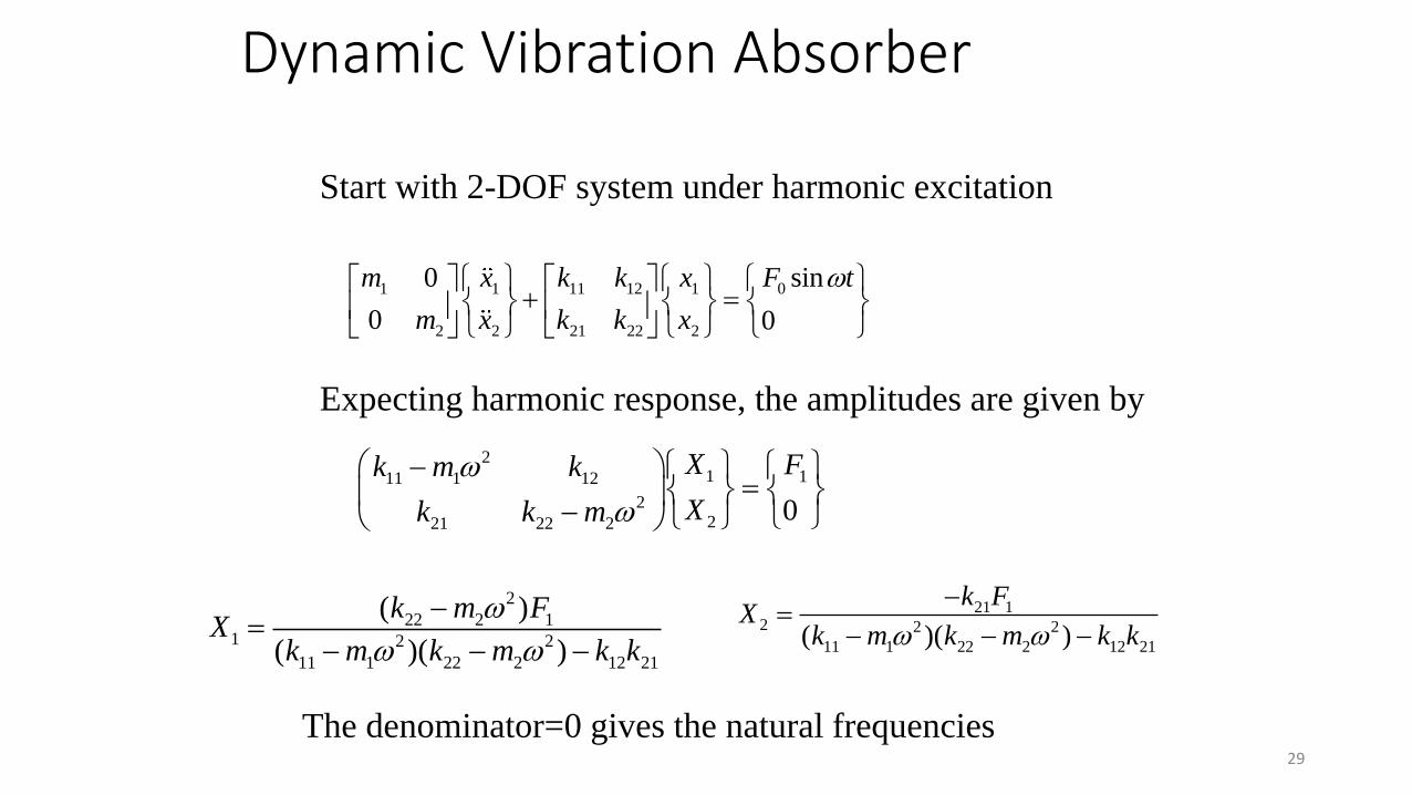
01 1 11 12 1
2 2 21 22 2
sin0
0 0
F tm x k k x
m x k k x
+ =
Start with 2-DOF system under harmonic excitation
21 111 1 12
2221 22 2
0
X Fk m k
Xk k m
− =
−
Expecting harmonic response, the amplitudes are given by
2
22 2 11 2 2
11 1 22 2 12 21
( )
( )( )
k m FX
k m k m k k
−=
− − −
21 12 2 2
11 1 22 2 12 21( )( )
k FX
k m k m k k
−=
− − −
The denominator=0 gives the natural frequencies
Dynamic Vibration Absorber
30
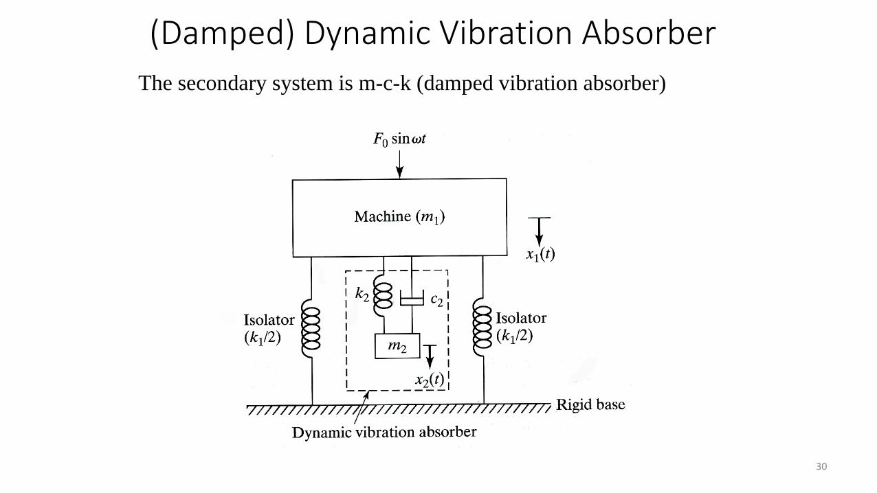
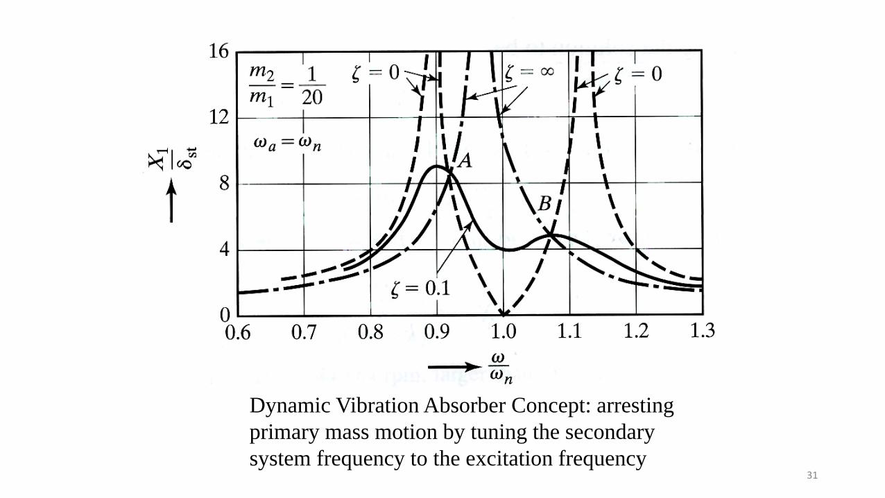
The secondary system is m-c-k (damped vibration absorber)
(Damped) Dynamic Vibration Absorber
31
Dynamic Vibration Absorber Concept: arresting
primary mass motion by tuning the secondary
system frequency to the excitation frequency