Embed Size (px)
Citation preview
International Research Journal of Engineering and Technology (IRJET) e-ISSN: 2395-0056
Volume: 02 Issue: 07 | Oct-2015 www.irjet.net p-ISSN: 2395-0072
© 2015, IRJET ISO 9001:2008 Certified Journal Page 561
HARMONIC ANALYSIS AND ITS MITIGATION TECHNIQUE IN
INDUSTRIAL ENVIRONMENT
T. Muni Jahnavi1, G. Rajesh2, Dr. B. Sarvesh3
1 Student, Department of EEE, JNTU Anantapur, Andhra Pradesh, India 2 Senior Manager, Engineering & Designs, Amara Raja Power Systems Limited, Karakambadi, Andhra Pradesh,
India 3 Professor, Department of EEE, JNTU Anantapur, Andhra Pradesh, India
---------------------------------------------------------------------***---------------------------------------------------------------------Abstract: With the advent of modern electronics, most of the industrial loads became nonlinear (E.g., Variable frequency drives, rectifier loads and UPS) in electrical systems. These loads are main sources of generating harmonics in the system. The presence of Harmonics in an industry will often result in malfunctioning of the electrical system. Harmonics is one of the major power quality issues in many processing industries like Cement industry, Marble industry, Steel plants, Rolling mills, Printing mills, Quarries, Battery manufacturing industry etc.,. Lower order harmonics cause major problems in most of these industries. In the case of a battery manufacturing industry, Charge & Discharge cycles are required for battery testing. For this process rectifiers are used which are nonlinear loads and induce harmonics into the system.
For harmonic reduction, there is a need to identify, measure the type & level of harmonics in a system. Thus detailed power quality analysis must be done. And then a solution has to be provided for reducing harmonic levels in the system. Amara Raja is one of the such valve regulated lead acid battery manufacturing industries. Hence, Harmonic study is done in that industry and measurement of the level of harmonics is done through 3ph power analyzer. After measurement, it was found that 5th order & 7th order harmonics were beyond the IEEE limits. Then detuned filter was designed. After installation of harmonic filter, harmonic measurement was done again and it is found that the 5th & 7th order harmonic contents were below the IEEE limits.
Index Terms- Harmonic reduction, Detuned Filter design, Battery industry.
1.INTRODUCTION:
Highest power tariff is paid by Indian industry and the gap between supply and demand is expanding due to low power factor and lower quality of power resulting in loss of production and profits[1]. In order to reduce the kVA demand and to improve the
power quality of the system, maintaining high power factor was considered as the only necessary parameter in earlier days. Hence, more emphasis was placed on finding solutions to improve the power factor. But in the presence of harmonic-rich environment, mere PF improvement does not meet the challenge of improving the power quality. Hence, mitigation techniques of harmonics are of great importance in industrial electrical systems in order to increase system reliability, to reduce the losses in rotating machines, to avoid capacitor failures, and nuisance tripping of protection relays[2], [3]. Besides Load flow and stability studies, Reactive power flow studies, and power system studies should also contain harmonic analysis and the harmonic analysis studies for industrial systems [4], [5]. Here, harmonic analysis is done through power analyzer. HARMONICS: Power quality has caused a great concern to electrical system engineers with the increasing usage of nonlinear loads like Static power converters, Rectifiers, Arc furnaces, Computers, Telecommunication equipment, Television receivers, Saturated transformers etc.,[6]. These nonlinear loads result in generation of harmonics. High level of harmonic distortion is harmful to various equipment within the installation and it also affects the utility as well as plant distribution systems. The Total Harmonic Distortion (THD) is a measure of the effective value of harmonic distortion.
. . . (1)
Where THD is the total harmonic distortion of the waveform in %, is the magnitude of the fundamental
component and are the magnitudes of the 2nd ,
3rd, . . . and harmonic components.
As already stated, rectifiers constitute a large
percentage of the nonlinear loads in the battery-manufacturing industry. Thus, mere installation of capacitor banks in the harmonic-rich environment does

International Research Journal of Engineering and Technology (IRJET) e-ISSN: 2395-0056
Volume: 02 Issue: 07 | Oct-2015 www.irjet.net p-ISSN: 2395-0072
© 2015, IRJET ISO 9001:2008 Certified Journal Page 562
not maintain the target power factor and does not improve the quality of power. That is why harmonic reduction techniques are required.
2. MITIGATION TECHNIQUES FOR REDUCTION OF HARMONIC DISTORTION:
Installation of harmonic filters would help in the reduction of harmonics. Generally, a harmonic filter comprises an inductor and a capacitor. Harmonic filters are mainly classified into Passive harmonic filters, Active harmonic filters[7], [8] and Hybrid harmonic filters. The passive harmonic filters prevent the undesirable harmonic current flow into the power system by providing a high series impedance to block their flow, or a low-impedance parallel path is provided to divert the harmonic currents [9]. The passive filters are mainly used in supply networks to reduce the high level harmonic distortion, to improve the power factor by reactive power compensation at fundamental frequency and to avoid the overloading of the capacitors. The active harmonic filters are the ideal solution for installations which are having a large number of single-phase and three-phase loads generating harmonics such as Computers, UPC, Lifting equipment. These are also used for elimination/reduction of problems like voltage sags and flickers occurring in the distribution networks. The third type of filter is hybrid filter and it is composed of both active and passive filter. In this work, detuned passive harmonic filter is designed and is considered as a mitigation technique for harmonic reduction.
3. DESIGN OF A DETUNED HARMONIC FILTER:
A detuned harmonic filter consists of a power capacitor and a tuning reactor. It will act in parallel with the fixed capacitor banks. For design purpose, data regarding load details, existing power factor, targeted new power factor, voltage and current total harmonic distortion etc., should be collected and this data is obtained from a power analyzer.
The harmonic filter design can be done in the
following steps:
STEP-A: Harmonic analysis is done at Amara Raja IBD MVRLA division at transformer-1 of rating 2000 kVA and electrical data such as total load, average monthly power PF, maximum load current, voltage and current total harmonic distortions are obtained from power analyzer. These details are given in Table 1 and it is as follows:
Table 1: Electrical Data of Battery Industry
S. N0. Parameters Value
1 Total load(kW) 414.32
2 Average monthly PF 0.773
3 Maximum load current 752 A
4 6.9%
5 49.5%
STEP-B: Assuming the targeted power factor to be 1.0, Calculate the required total kVAr to raise the power factor from 0.773 to 1.0.
kVAr required = kW * (tan ) . . . (2)
Existing PF = 0.773 ∴ tan = 0.821,
Target PF = 1.0 ∴ tan = 0,
kVAr required = 414.32 * 0.821 = 340.04 kVAr ≌ 350 kVAr. Out of 350 kVAr calculated from Eqn. (2), we employ 10% kVAr for no load loss of transformer, 20% kVAr for base load and remaining kVAr for PF correction. Filter kVAr = 70% of 350 kVAr = 245 kVAr
But generally standard ratings of the capacitors available in the market are in the ranges of 12.5, 25, 50 and 100 kVAr respectively. So, we consider 250 kVAr as the filter kVAr. STEP-C Design of filter: A detuned filter consists of 3 capacitors connected in delta and 3 reactors connected to it in series. We need to calculate the tuning factor%, reactor and capacitor values in mH/phase and µF/phase and also their kVAr values respectively. Step-1 Calculation of Tuning factor %: In order to reduce the harmonic contents and to avoid resonance, the reactors used must be some percentage of capacitors used i.e., ‘Tuning Factor’. Percentage tuning factor is defined as,
P= . . . (3)
Substituting reactor reactance i.e. 2.Π. .L and Capacitor reactance i.e. at the system frequency Eqn. (3) can be written as,
International Research Journal of Engineering and Technology (IRJET) e-ISSN: 2395-0056
Volume: 02 Issue: 07 | Oct-2015 www.irjet.net p-ISSN: 2395-0072
© 2015, IRJET ISO 9001:2008 Certified Journal Page 563
= 4. . L. C. . . . (4)
The resonance frequency is given as,
= . . . (5) Using Eqns. (4) & (5), tuning factor “p” is given as,
= . . . (6)
The following criteria should be considered for matching of the reactors and capacitors to obtain optimum performance from a detuned filter:
• The resonance frequency is considered according to the most lower order predominant harmonics in the system.
• The capacitor voltage across the terminals will increase due to inductive reaction of the reactor. So, capacitors must be chosen 10% above its actual rated voltage.
• Due to the presence of higher voltage rated capacitors and reactors in a harmonic filter, rated reactive power is not obtained. So, the obtained power must be calculated in order to avoid low compensation.
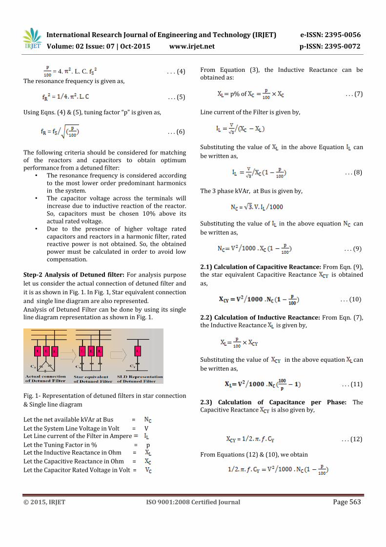
Step-2 Analysis of Detuned filter: For analysis purpose
let us consider the actual connection of detuned filter and
it is as shown in Fig. 1. In Fig. 1, Star equivalent connection
and single line diagram are also represented.
Analysis of Detuned Filter can be done by using its single line diagram representation as shown in Fig. 1.
Fig. 1- Representation of detuned filters in star connection
& Single line diagram
Let the net available kVAr at Bus =
Let the System Line Voltage in Volt = V Let Line current of the Filter in Ampere
Let the Tuning Factor in % = p Let the Inductive Reactance in Ohm =
Let the Capacitive Reactance in Ohm =
Let the Capacitor Rated Voltage in Volt =
From Equation (3), the Inductive Reactance can be obtained as:
= p% of = × . . . (7)
Line current of the Filter is given by,
=
Substituting the value of in the above Equation can
be written as,
= . . . (8)
The 3 phase kVAr, at Bus is given by,
=
Substituting the value of in the above equation can
be written as,
= . . . (9)
2.1) Calculation of Capacitive Reactance: From Eqn. (9), the star equivalent Capacitive Reactance is obtained
as,
= . . . (10)
2.2) Calculation of Inductive Reactance: From Eqn. (7), the Inductive Reactance is given by,
= ×
Substituting the value of in the above equation can
be written as,
= . . . (11)
2.3) Calculation of Capacitance per Phase: The Capacitive Reactance is also given by,
= . . . (12)
From Equations (12) & (10), we obtain
=

International Research Journal of Engineering and Technology (IRJET) e-ISSN: 2395-0056
Volume: 02 Issue: 07 | Oct-2015 www.irjet.net p-ISSN: 2395-0072
© 2015, IRJET ISO 9001:2008 Certified Journal Page 564
From the above equation, capacitance per phase can be obtained as,
= in Farad . . . (13)
Capacitance per phase in µF is given by,
= . . . (14)
2.4) Calculation of Inductance per Phase: The Inductive Reactance is also given by,
= 2. π. f. L . . . (15)
From Equation (7), the Inductive Reactance is given by,
= ×
Substituting the equations (15) & (12) in the above equation,
2. π. f. L = ×
From the above equation, Inductance per Phase can be obtained as,
L = × in Henry . . . (16)
2.5) Calculation to Estimate the Rated Voltage of the
Filter Capacitor: Consider Fig. 2 for the calculation of
rated voltage of the capacitor .
Fig. 2- Single Line Diagram of detuned filter
From Fig. 1,Line current I is given by,
I = = . . . (17)
Voltage across the capacitor is given by,
= I.
Substituting the value of I in the above equation can be
written as,
=
Allowing 10% for over voltage, the rated voltage of the
capacitor is given by,
= . . . (18)
2.6) Calculation of kVAr of the Capacitor: The kVAr of the capacitor at its rated voltage is given by, kVAr of capacitor = . . . (19) Substituting in the above equation, we obtain
kVAr of the capacitor = × × (1 - ) . . . (20)
During measurements we found that 5th order
and higher order harmonics were beyond their limits as per IEEE Standards 519[10]. So, we opted to design detuned filters with tuning factor as 7%. The 7% detuned filters are suitable for use in majority of installations where the dominant harmonics are higher than 189 Hz like 5thand higher. The 250 kVAr harmonic filter (stated earlier) is designed with four no.’s of 50 kVAr and two no.’s of 25 kVAr harmonic filters. The values such as reactor and capacitor in mH/phase and µF/phase and also their kVArs required for designing a harmonic filter are calculated by using above specified equations by considering the tuning factor as 7% and the values are given in Table 2. Table 2: For 7%, 440 Volts Detuned Filters
Bus kVAr
in
Ω
in Ω in
µF/ph
L in mH/ph
in
V
kVAr at
25
8.327
0.583
382.46
1.856
525
33.1

International Research Journal of Engineering and Technology (IRJET) e-ISSN: 2395-0056
Volume: 02 Issue: 07 | Oct-2015 www.irjet.net p-ISSN: 2395-0072
© 2015, IRJET ISO 9001:2008 Certified Journal Page 565
50
4.163
0.291
765.01
0.928
525
66.2
4. INSTALLATION OF HARMONIC FILTER AND
MEASUREMENT:
After designing, the harmonic filter was fabricated
and installed in the plant. After installation harmonic
measurement was done again by 3ph power analyzer and
it was found that the 5th order and higher order harmonic
contents are reduced. The lower order harmonics of
voltage and current with and without filter are as shown
in Table 3 and Table 4; and graphically in Figure 3 and
Figure 4 respectively.
Table 3: Measured Voltage Harmonics by Power Analyzer
S. No. Order of
Harmonics
Harmonics in
% without
filters
Harmonics in
% with filters
1. 5th 6.7 3.1
2. 7th 1.2 1.1
3. 11th 0.7 0.2
4. 13th 0.4 0.1
Table 4: Measured Current Harmonics by Power Analyzer
S. No. Order of
Harmonics
Harmonics in
% without
filters
Harmonics in
% with filters
1. 5th 48.2 14.4
2. 7th 4.1 2.9
3. 11th 2.4 1.5
4. 13th 1.9 0.9
Fig. 3 - Voltage variation of different harmonic order
Fig. 4 - Current variation of different harmonic order
5. RESULTS OF HARMONIC MEASUREMENT:
The following observations are made:
(1). Input line current is reduced from 752 A to 655 A.
(2). kVA demand is reduced from 536.1 kVA to 465.1 kVA.

International Research Journal of Engineering and Technology (IRJET) e-ISSN: 2395-0056
Volume: 02 Issue: 07 | Oct-2015 www.irjet.net p-ISSN: 2395-0072
© 2015, IRJET ISO 9001:2008 Certified Journal Page 566
(3). Input PF is improved from 0.773 to 0.994.
(4). is reduced from 6.9% to 3.2%.
(5). is reduced from 49.5% to 14.3%.
6. CONCLUSIONS:
This work presents design and results of 7% detuned passive harmonic filters (reactors) in the plant. The installation of detuned filters under harmonic conditions shows reduction of harmonics in the plant. The 5th order current and voltage harmonics for the uncompensated system are found to be 48.2% and 6.7% respectively. After compensating with the 7% detuned passive harmonic filter, the 5th order current and voltage harmonics are found to be 14.4% and 3.1% respectively.
The power factor is increased from 77% to 99% and burning of capacitor contactors is avoided after installing detuned filters.
The line current is found to have reduced by 13.64% which results in less line losses and less heating of cables.
This solution is preferable for the installations where the final objective is reactive power compensation at the fundamental frequency and for the reduction of lower most predominant harmonics like 5th and 7th order harmonics.
REFERENCES:
[1] Ashish Pandey, Kothari D.P. and Bhatt S.S., “Power
Quality Issues and Power Electronics” International
Journal Energy Technology and Policy, Vol. 4, pp 4-18,
2006.
[2] Walter T.J. Hulshorst, Keet L. and John Enslin E.R., “Harmonic Analysis and Mitigation in Large Industrial Steel Plants” Electrical Power Quality and Utilization Magazine, Vol. 11, pp 57-63, 2006. [3] M. Z. El-Sadek, Power system harmonics, 2nd edition, Mukhtar Press, Egypt, 2007. [4] IEEE Std 399-1997, Recommended practice for industrial and commercial power systems analysis, ANSI/IEEE, 1997. [5] Khatavkar V.V., Chapbekar S.N., “Study of Harmonics in Industries - Power Quality Aspect”, Electrical India Magzines, Vol. 46, pp 188-192, 2006.
[6] Elham B. Makram, Kasikci, “Harmonics and Quality of Power” Proceedings of Ninth International Conference, IEEE, Vol.3, pp 810 - 815, 2000. [7] António P. Martins, “The Use of an Active Power Filter for Harmonic Elimination and Power Quality Improvement in A Nonlinear Electrical Installation”. IEEE Transactions on Industrial Electronics, pp 1-5, 2000. [8] Escobar, G., Stankovic, Cardenas A.M., Mattavelli V.P., “An Adaptive Controller for a Series Active Filter to Compensate Voltage Sags, Unbalance and Harmonic Distortion”, Proceedings of VIII IEEE Technical Proceedings, pp. 275 - 280, 20-24, 2002. [9] B. Singh, B. N. Singh, A. Chandra, K. Al-Haddad, A. Pandey, and D. P. Kothari, “A review of three-phase improved power quality AC-DC converters,” IEEE Transactions on Industrial Electronics, vol. 51, no. 3, pp. 641–660, 2004. [10] IEEE Std 519, Recommended practice and requirements for harmonics control in electrical power systems, ANSI/ IEEE, 1992.


![LV - Power Factor Correction and Harmonic Mitigation … List Contents Power Factor Correction Products Description kVAr Rating Minimum Ordering Quantity (No.) Reference Unit MRP [`]](https://img.pdfslide.us/doc/110x75/5ae474457f8b9a7b218e6b00/lv-power-factor-correction-and-harmonic-mitigation-list-contents-power-factor.jpg)