Embed Size (px)
Citation preview

Hardware write block (HWB) device
EPOS BadDriveAdapter User guide

2
EPOS LLC 44, Verkhniy Val str., Kiev, 04071, Ukraine
www.epos.ua
August 2011 Ver. 1.0
Sales and support EPOS Data Recovery Center
34, Verkhniy Val str., Kiev, 04071, Ukraine www.epos.ua/recovery
Tel.: +380 (44) 467-7540 Fax: +380 (44) 467-7547
e-mail: [email protected]
© 2012. EPOS LLC.

3
Contents 1. Introduction ........................................................................................... 4
1.1. Overview........................................................................................................................................... 4
1.2. Package contents .............................................................................................................................. 5
1.3. Main features ................................................................................................................................... 5
1.4. Hardware write blocking .................................................................................................................. 5
1.5. About this guide ............................................................................................................................... 5
2. Installation ............................................................................................. 6
2.1. Physical layout and controls ............................................................................................................. 6
2.2. System specification ......................................................................................................................... 7
3. Quick start guide ..................................................................................... 8
4. Operation ................................................................................................ 9
4.1. General notes ................................................................................................................................... 9
4.1.1. Device usage ............................................................................................................................. 9
4.1.2. File manager recommendations ............................................................................................... 9
4.2. Device connection .......................................................................................................................... 10
4.2.1. Connecting SATA HDD ............................................................................................................ 10
4.2.2. Connecting 3,5" PATA (IDE) HDD ............................................................................................ 11
4.2.3. Connecting 2,5" PATA (IDE) HDD ............................................................................................ 12
4.2.4. Connecting 1,8" PATA (IDE) HDD ............................................................................................ 13
4.2.5. Connecting 1,8" ZIF PATA (IDE) HDD ...................................................................................... 14
4.3. Operation modes ............................................................................................................................ 15
4.3.1. “Mask Error” – reading errors masking mode ........................................................................ 16
4.3.2. “Read Sector” – sector and cluster instructions intercept mode ........................................... 18
4.3.3. “Check Drive” – storage drive testing mode .......................................................................... 18
4.4. Messages displayed ........................................................................................................................ 19
Appendix 1. Allowed instructions .............................................................. 20
Appendix 2. Supported ATA instructions ................................................... 21
Appendix 3. Glossary ................................................................................ 23

4
1. Introduction
1.1. Overview
EPOS BadDriveAdapter (hereinafter referred to as “device”) is a specialized hardware write block (HWB) device1 for data recovery from the hard drives with defective and unstably readable sectors. Device application allows to begin the recovery of the user files without preliminary copying of the damaged hard drive, which shortens the general information recovery time, especially on high capacity HDDs and RAID systems.
The device is inserted in the opening of SATA HDD interface and analyses the instructions transferred via the interface. At the absence of errors in the HDD the device acts as a HWB device. If an instruction is completed with an error or timed out (for example in case of reading from bad sector), the device takes over the control of the disk and blocks the transmission of the error message into the system. Moreover, depending on the type of defect, either read data or marker of the bad sector is transmitted to the computer.
As a result, standard operating system and applications work with damaged HDD as with operable one, without possible error messages and hanging. This allows immediate beginning of the information analysis and recovery.
1 “HWB device” is a name according to NIST Hardware Write Blocker Device (HWB) Specification v.2.0

5
1.2. Package contents
Name P/n Delivery set Quantity EPOS BadDriveAdapter EWP-001 WP-01 1 SATA interface cable EWP-002 WP-01 2 Power cable 4pin P4-SATA power EWP-003 WP-01 1 Power cable 4pin P4-4pin Molex EWP-004 WP-01 1 User guide EWP-005 WP-01 1 Ticket (technical passport) EWP-006 WP-01 1 SATA-PATA adapter EWP-007 WP-02 1 Universal adapter for 2,5” PATA HDD, 1,8” ZIF PATA HDD/SSD, 1,8” PATA HDD/SSD
EWP-008 WP-02 1
eSATA-SATA interface cable EWP-009 WP-02 1 Power supply unit 5V, 12V 2A EWP-010 WP-02 1
1.3. Main features
Data recovery from HDD with defective and unstably readable sectors without intermediate copying;
Built-in hardware write blocking;
Transparent for software;
Hot plugging;
Manual disabling of write blocking;
Supports HDDs of any capacity;
No driver setup needed;
Small and lightweight.
1.4. Hardware write blocking
Hardware write blocking implemented in the device is intended to prevent accidental or intentional data modification on HDD during recovery or copying procedures.
In write blocking mode the device is completely transparent for hardware and software. Thus, it is possible to use any platform (DOS, Windows, Linux, MacOS, UNIX, etc.) and any special software (EnCase, X-Ways Forensics, The Sleuth Kit, etc.)
1.5. About this guide
Thank you for purchasing the EPOS BadDriveAdapter. Before the start of device exploitation, read this manual carefully and save it for reference.
EPOS LLC continuously improves its products. Device specifications and manual are subject to change without prior notice.

6
2. Installation
2.1. Physical layout and controls
1 / 10 – SATA interface sockets connecting respectively host computer (Host side) and investigated HDD (Device side).
2 / 11 – power interface sockets connecting respectively device (Host side) and investigated HDD (Device side).
3 – write blocking switch. Provides manual enabling/disabling of write blocking. When write blocking is disabled, LED WP (Write Blocking) glows.
4 – liquid crystal display.
5 – button “Display clear”. Resets and clears the data on the LCD.
6 – LED “Ready” (RDY). Glows when device is ready for operation.
7 – LED “Write Blocking” (WP). Glows when write blocking is disabled.
8 – LED “Device activity” (RDA). Blinks when data reading is controlled by the device.
9 – LED “Host activity” (Rdh). Blinks when data reading is controlled by the host computer.
12 – switch “DIP”. Selects the device operation mode. See the legend below.

7
Operation mode selection (DIP switch legend)
Check Drive – diagnostic mode.
Read Sector – read instructions intercept mode with sector-by-sector reading.
Mask Error – reading with error masking mode, timeout 5 seconds.
Mask Error – reading with error masking mode, timeout 1 second.
Mask Error – reading with error masking mode, timeout 0,1 second.
2.2. System specification
Interface: Serial ATA (in and out).
Supported HDDs: SATA 2,5”/3,5”, PATA 1,8”/2,5”/3,5” (with adapter), ZIF PATA 1,8” (with adapter).
Indication: bad sectors quantity, data transfer rate, data transfer mode.
OS compatibility: all (including DOS, Windows XP, Vista, 7, Linux, MacOS, UNIX).
Power supply: +5V, +12V (in and out)
1 2 3 4
1 2 3 4
1 2 3 4
1 2 3 4
1 2 3 4

8
3. Quick start guide
The common HDD connection procedure consists of the following steps:
Turn the host computer off (unless hot plugging is available);
Connect the investigated HDD to the device;
Connect the device to the host by SATA interface cable;
Connect the power supply cable of the device to the power unit of the host;
Turn the host computer on (unless hot plugging is available);
When the device becomes ready for operation, the LED RDY (Ready) lights up;
If SATA controller and its drivers in the host OS do not support PlugAndPlay connection, perform the drive detection manually.
Perform the desired operations with the investigated HDD as if it is installed into the host computer directly.
After finishing the work with the investigated HDD, first disconnect the device from the host computer, and then disconnect the HDD.
“Hot plugging” the device to a computer requires:
AHCI mode of SATA controller (set in BIOS);
SATA controller supporting the hot plugging;
SATA driver in OS supporting the hot plugging.
Otherwise, shutting down is required to connect the device.

9
4. Operation
4.1. General notes
4.1.1. Device usage
1. The device does not support hot plugging into host SATA ports that set "Multiword DMA" or "PIO" data transfer mode in the process of hot detection. To connect the device (together with a storage drive) to such port, the computer must be turned off.
If the storage drive switches to "Multiword DMA" or "PIO" mode, the BadDriveAdapter automatically detects this and displays respectively “HostDMA mode” or “HostPIO mode” message in the upper line of display and “Read Bypass” message in the lower line.
If the “Read Bypass” message is shown at the lower line of the device display, the reading instructions from host computer are transferred directly to the storage drive. In this case only write blocking is used (unless turned off manually).
2. The list of operation modes by bad sectors reading speed, descending:
• Mask Error, TimeOut = 0,1 sec (fastest).
• Mask Error, TimeOut = 1,0 sec.
• Mask Error, TimeOut = 5,0 sec.
• Read Sector (slowest).
3. The list of operation modes by bad sectors reading quality (valid data amount), descending:
• Read Sector (accurate);
• Mask Error, TimeOut = 5,0 sec;
• Mask Error, TimeOut = 1,0 sec;
• Mask Error, TimeOut = 0,1 sec (inaccurate).
4.1.2. File manager recommendations
For "Read Sector" operation mode it is recommended to use software which is able to re-read bad blocks in sector-by-sector mode (for example, R - Studio, WinHex) or cluster-by-cluster mode (for example, UFS, Windows Explorer)
If “Total Commander” file manager is used, set it to sector-by-sector data re-reading.

10
4.2. Device connection
Before proceeding, be sure to read quick start guide (section 3) to learn the basic device connection rules.
4.2.1. Connecting SATA HDD
SATA HDD connection
The SATA HDDs are connected in following steps:
1. Connect the HDD to the device by SATA interface and power cables; 2. Connect the device to host by SATA interface cable; 3. Connect the power supply cable of the device to the power unit of the host.
Computer

11
4.2.2. Connecting 3,5" PATA (IDE) HDD
3,5” PATA HDD connection
The 3,5" IDE HDDs are connected using SATA-PATA adapter in following steps:
1. Before connecting a PATA HDD, make sure it is set to “Master/Single” mode (see the HDD label for instructions);
2. Connect the adapter to the HDD interface socket so that the power connector on the adapter is on the opposite side from the HDD power connector (see the figure);
SATA-PATA adapter connected to a 3,5" HDD
3. Connect the Y-shaped power cable (4pin P4 - 4pin Molex) to the adapter, HDD and the device;
4. Connect the SATA interface cable to the adapter and the device.
Computer
12
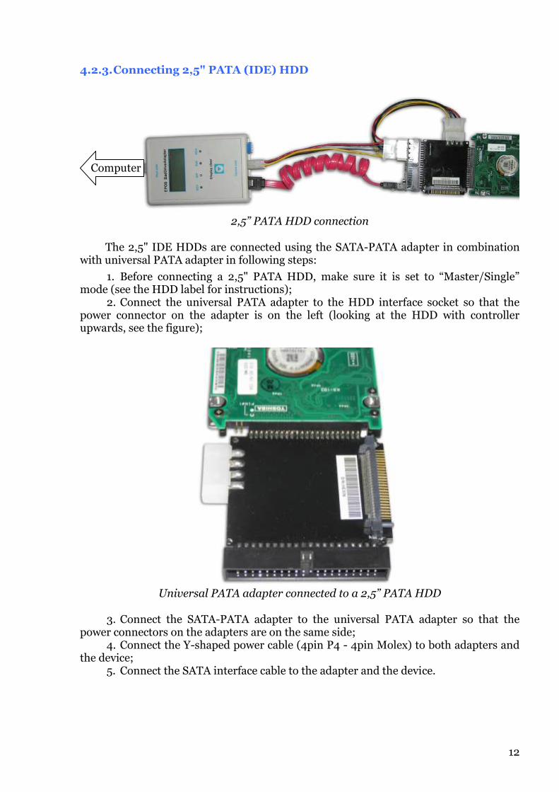
4.2.3. Connecting 2,5" PATA (IDE) HDD
2,5” PATA HDD connection
The 2,5" IDE HDDs are connected using the SATA-PATA adapter in combination with universal PATA adapter in following steps:
1. Before connecting a 2,5" PATA HDD, make sure it is set to “Master/Single” mode (see the HDD label for instructions);
2. Connect the universal PATA adapter to the HDD interface socket so that the power connector on the adapter is on the left (looking at the HDD with controller upwards, see the figure);
Universal PATA adapter connected to a 2,5” PATA HDD
3. Connect the SATA-PATA adapter to the universal PATA adapter so that the power connectors on the adapters are on the same side;
4. Connect the Y-shaped power cable (4pin P4 - 4pin Molex) to both adapters and the device;
5. Connect the SATA interface cable to the adapter and the device.
Computer

13
4.2.4. Connecting 1,8" PATA (IDE) HDD
1,8” PATA HDD connection
The 1,8" IDE HDDs are connected using the SATA-PATA adapter in combination with universal PATA adapter in following steps:
1. Connect the universal PATA adapter to the HDD interface socket (looking at the HDD with controller upwards);
Universal PATA adapter connected to a 1,8" PATA HDD
2. Connect the SATA-PATA adapter to the universal PATA adapter so that the power connectors on the adapters are on the same side;
3. Connect the Y-shaped power cable (4pin P4 - 4pin Molex) to both adapters and the device;
4. Connect the SATA interface cable to the adapter and the device.
Computer

14
4.2.5. Connecting 1,8" ZIF PATA (IDE) HDD
1,8” ZIF PATA HDD connection
The 1,8" ZIF IDE HDDs are connected using the SATA-PATA adapter in combination with universal PATA adapter in following steps:
1. Connect the universal PATA adapter to the HDD interface socket so that the power connector on the adapter is on the right (looking at the HDD with controller upwards, see the figure);
Universal PATA adapter connected to a 1,8" ZIF PATA HDD
Make sure that the colored label on the ZIF cable terminal is visible when looking at the HDD with controller upwards.
2. Connect the SATA-PATA adapter to the universal PATA adapter so that the power connectors on the adapters are on the same side;
3. Connect the Y-shaped power cable (4pin P4 - 4pin Molex) to both adapters and the device;
4. Connect the SATA interface cable to the adapter and the device.
Computer

15
4.3. Operation modes
One of the most widespread reasons of the information loss is the destruction of hard disk coating. The main problem in such cases is that the destructions spread quickly, thus from a certain moment this process becomes irreversible. This can result in complete loss of all data in the process of information recovery.
At the same time, the amount of defects can be insignificant and their exposure during the diagnostics can take a long time.
Standard information recovery procedure includes the creation of complete image of the medium. This allows solving the two problems:
To fix the data defects;
To avoid the modification of the original data.
Nevertheless, the data copying from modern high-capacity HDDs takes a lot of time. Even at 3-4 GB/min data rate, the complete copying of 1 TB takes 4-5 hours.
EPOS BadDriveAdapter eliminates the problems related to the data copying and recovery. Three operation modes are available.
In the “Mask Error” mode the errors are masked with special marker “MASK” (0x4D 0x41 0x53 0x4B) depending on the instruction completion code or the execution timeout.
This mode is intended for the fast copying when it is unknown, whether bad sectors are present on the disk. The best results are received when physical damage is in the non-critical areas of HDD (not in the area of file tables like MFT, FAT etc.).
This mode provides selectable timeouts 0.1 s, 1.0 s, 5.0 s. The less the timeout, the higher the data transfer rate. This mode also blocks the unstable sectors re-reading by the drivers or software (so the data transfer rate is increased).
In the “Read Sector” mode the device intercepts sector and cluster reading instructions. The mode is intended for the recovery (copying) of information from HDD with special software, providing sector-by-sector or cluster-by-cluster reading of defective areas.
If the “Read Bypass” message is shown at the lower line of the device display, the reading instructions from host computer are transferred directly to the storage drive. In this case only write blocking is used (unless turned off manually).
The change of operation modes and TimeOut values can be done at any time, even during the device operation. Any change takes effect when the next reading instruction code is received from the host system.
In the “Check Drive” mode the HDD is diagnosed and the number of instructions completed with an error is displayed on the screen of the device. This mode is recommended for the HDD analysis.

16
4.3.1. “Mask Error” – reading errors masking mode
The “Mask Error” mode is intended for automatic masking of real or potential reading instruction execution errors.
Mode features:
Masks the instructions completed with errors;
Masks the instructions that might be completed correctly, but take more time than the set TimeOut interval;
Blocks bad sector reading;
Does not support special software.
The allowed reading instruction execution time (TimeOut) is set manually and can be 0.1 s, 1.0 s, 5.0 s.
In this operation mode the device counts and displays the number of masked instructions «nMSK».
To switch the device to “Mask Error” mode, set the DIP switch according to the following table.
TimeOut = 5.0 s
TimeOut = 1.0 s
TimeOut = 0.1 s
DIP switch positions in the “Mask Error” mode.
If the “Read Bypass” message is shown at the lower line of the device display, the reading instructions from host computer are transferred directly to the storage drive. In this case only write blocking is used (unless turned off manually).
Two masking methods are used in this operation mode:
Masking by instruction completion code;
Masking by instruction execution timeout.
1 2 3 4
1 2 3 4
1 2 3 4

17
4.3.1.1. Masking by instruction completion code
This method is applied when a storage drive completes an instruction within the set TimeOut interval. In this case the device masks the error flag bit (ERR) in the “Status” register, which is returned by a storage drive after the reading instruction is executed.
Composition of data transferred to the host system in this case depends on the size of instruction (amount of sectors, specified in the instruction parameters) and the position of the bad sector in the specified block of sectors.
If a one-sector instruction is completed with an error, or a bad sector is the first in a block, the storage drive might pass no data to the host system. In this case the device sends the host system the data containing special markers “MASK” (0x4D 0x41 0x53 0x4B) and masks the error flag bit (ERR) in the “Status” register.
If a bad sector is located inside the read block the HDD sends the host system the full amount of data specified in an instruction. In such block only the data before the bad sector are valid. The subsequent data may contain, for example, values of status register, error register or other information.
4.3.1.2. Masking by instruction execution timeout
This method is applied when a storage drive does not complete an instruction within the set TimeOut interval. In this case the device interrupts the instruction execution, prepares the HDD to the reception of the next instruction from the host system and sends the host system the amount of data that was not sent by the HDD. The masking markers “MASK” (0x4D 0x41 0x53 0x4B) are used to substitute the missing data.

18
4.3.2. “Read Sector” – sector and cluster instructions intercept mode
The “Read Sector” mode is intended for interception of all one-sector and cluster (1-8 sectors) reading instructions, from the host system. The intercepted instructions are execution is controlled by the device (cluster instructions are executed sector-by-sector).
Mode features:
All instructions sent by the host system are executed successfully;
Instructions with sector reading errors are masked with the marker “BAD” (0x42 0x41 0x44).
In this operation mode the device counts and displays the number of bad sectors “nBAD”.
To switch the device to “Read Sector” mode, set the DIP switch according to the following figure.
DIP switch positions in the “Read Sector” mode.
If the “Read Bypass” message is shown at the lower line of the device display, the reading instructions from host computer are transferred directly to the storage drive. In this case only write blocking is used (unless turned off manually).
4.3.3. “Check Drive” – storage drive testing mode
The “Check Drive” mode is intended for discovery and count of reading completed with errors – “nERR”. All reading instructions are transferred directly to HDD without intervention of the device.
To switch the device to “Check Drive” mode, set the DIP switch according to the following figure.
DIP switch positions in the “Check Drive” mode.
If the “Read Bypass” message is shown at the lower line of the device display, the reading instructions from host computer are transferred directly to the storage drive. In this case only write blocking is used (unless turned off manually).
1 2 3 4
1 2 3 4

19
4.4. Messages displayed
In each operation mode the device screen displays the average (TRa=… MBs) and instantaneous (TRi=… MBs) data transfer rates along with mode-specific information.
“Mask Error” mode: once the TimeOut value “tOUT =” and then the mode name (“Mask Error”) and the number of masked instructions "nMSK =".
“Read Sector” mode: the mode name (“Read Sector”) and the number of bad sectors "nBAD =".
“Check Drive” mode: the mode name (“Check Drive”) and the number of reading instructions completed with errors "nERR =".
20
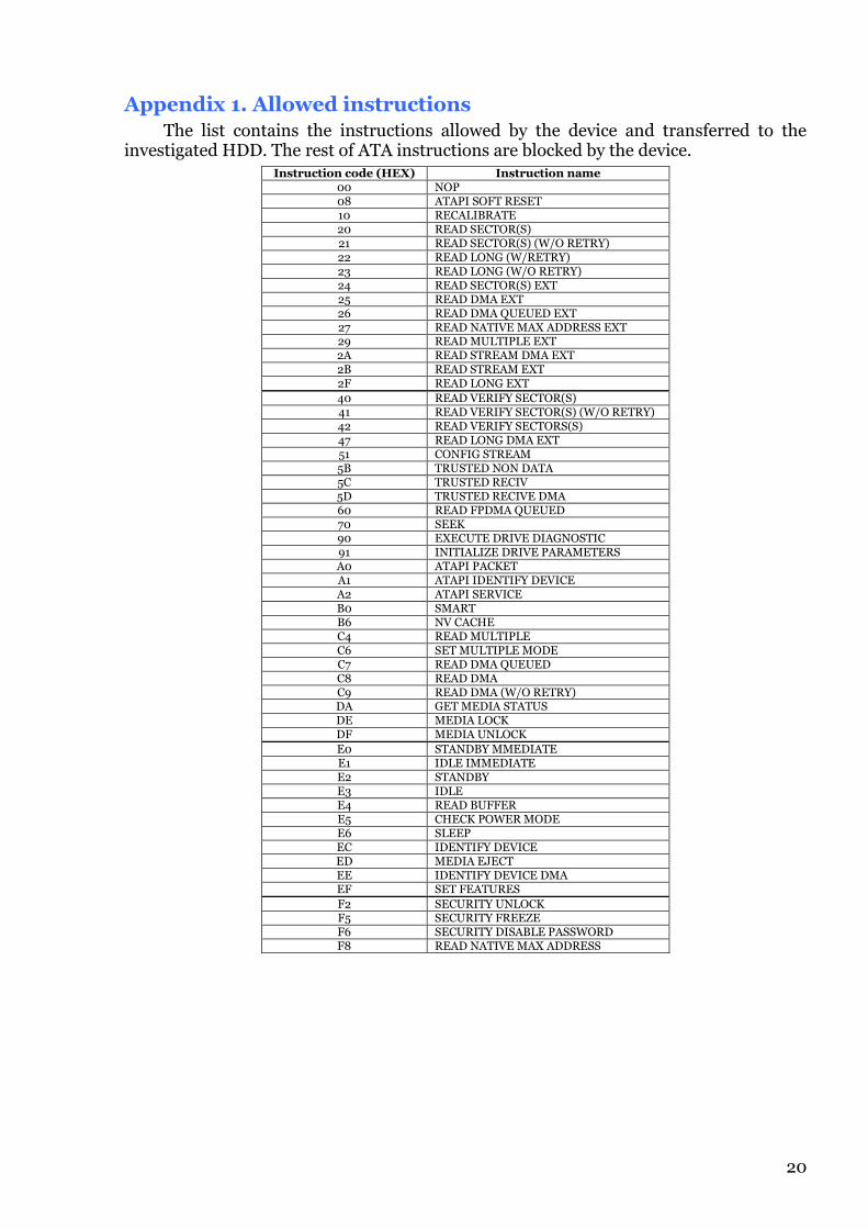
Appendix 1. Allowed instructions
The list contains the instructions allowed by the device and transferred to the investigated HDD. The rest of ATA instructions are blocked by the device.
Instruction code (HEX) Instruction name 00 NOP 08 ATAPI SOFT RESET 10 RECALIBRATE 20 READ SECTOR(S) 21 READ SECTOR(S) (W/O RETRY) 22 READ LONG (W/RETRY) 23 READ LONG (W/O RETRY) 24 READ SECTOR(S) EXT 25 READ DMA EXT 26 READ DMA QUEUED EXT 27 READ NATIVE MAX ADDRESS EXT 29 READ MULTIPLE EXT 2A READ STREAM DMA EXT 2B READ STREAM EXT 2F READ LONG EXT
40 READ VERIFY SECTOR(S) 41 READ VERIFY SECTOR(S) (W/O RETRY) 42 READ VERIFY SECTORS(S) 47 READ LONG DMA EXT 51 CONFIG STREAM 5B TRUSTED NON DATA 5C TRUSTED RECIV 5D TRUSTED RECIVE DMA 60 READ FPDMA QUEUED 70 SEEK 90 EXECUTE DRIVE DIAGNOSTIC 91 INITIALIZE DRIVE PARAMETERS A0 ATAPI PACKET A1 ATAPI IDENTIFY DEVICE A2 ATAPI SERVICE B0 SMART B6 NV CACHE C4 READ MULTIPLE C6 SET MULTIPLE MODE C7 READ DMA QUEUED C8 READ DMA C9 READ DMA (W/O RETRY) DA GET MEDIA STATUS DE MEDIA LOCK DF MEDIA UNLOCK
E0 STANDBY MMEDIATE E1 IDLE IMMEDIATE E2 STANDBY E3 IDLE E4 READ BUFFER E5 CHECK POWER MODE E6 SLEEP EC IDENTIFY DEVICE ED MEDIA EJECT EE IDENTIFY DEVICE DMA EF SET FEATURES
F2 SECURITY UNLOCK F5 SECURITY FREEZE F6 SECURITY DISABLE PASSWORD F8 READ NATIVE MAX ADDRESS

21
Appendix 2. Supported ATA instructions Instruction code (HEX) Instruction name Protocol
00 NOP ND
01 Reserved
02 Reserved
03 CFA REQUEST EXTENDED ERROR ND
04 Reserved
08 DEVICE RESET DR
12 RECALIBRATE
1B RECALIBRATE
1E RECALIBRATE
20 READ SECTORS PI
21 READ SECTORS WITHOUT RETRY PI
22 READ LONG PI
23 READ LONG WITHOUT RETRY PI
24 READ SECTORS EXT PI
25 READ DMA EXT DM
26 READ DMA QUEUED EXT DMQ
27 READ NATIVE MAX ADDRESS EXT ND
28 Reserved
29 READ MULTIPLE EXT PI
2A READ STREAM DMA EXT DM
2B READ STREAM EXT PI
2E Reserved
2F READ LOG EXT PI
30 WRITE SECTORS PO
31 WRITE SECTORS WITHOUT RETRY PO
32 WRITE LONG PO
33 WRITE LONG WITHOUT RETRY PO
34 WRITE SECTORS EXT PO
35 WRITE DMA EXT DM
36 WRITE DMA QUEUED EXT DMQ
37 SET MAX ADDRESS EXT ND
39 WRITE MULTIPLE EXT PO
3B WRITE STREAM EXT PO
3C WRITE VERIFY PO
3D WRITE DMA FUA EXT DM
3E WRITE DMA QUEUED FUA EXT DMQ
3F WRITE LOG EXT PO
40 READ VERIFY SECTORS ND
41 READ VERIFY SECTORS WITHOUT RETRY ND
42 READ VERIFY SECTORS EXT ND
43 Reserved
45 WRITE UNCORRECTABLE EXT ND
46 Reserved
47 READ LOG DMA EXT DM
4A Reserved
4B Reserved
4E Reserved
50 FORMAT TRACK VS
51 CONFIGURE STREAM ND
52 Reserved
53 Reserved
54 Reserved
55 Reserved
57 WRITE LOG DMA EXT DM
58 Reserved
5A Reserved
5B TRUSTED NON-DATA ND
5C TRUSTED RECEIVE PI
5D TRUSTED RECEIVE DMA DM
70 SEEK ND
90 EXECUTE DEVICE DIAGNOSTIC DD
91 INITIALIZE DEVICE PARAMETERS ND
92 DOWNLOAD MICROCODE PO
96 STANDBY
98 CHECK POWER MODE
A0 PACKET P
A1 IDENTIFY PACKET DEVICE PI
A2 SERVICE P/DMQ

22
Instruction code (HEX) Instruction name Protocol
A3 Reserved
A4 Reserved
A6 Reserved
A7 Reserved
A8 Reserved
AA Reserved
AC Reserved
AD Reserved
B0 SMART ND/PI/PO
B1 DEVICE CONFIGURATION ND/PI/PO/DM
B6 NV CACHE DM/ND
B9 Reserved for CFA
BA Reserved for CFA
BB Reserved for CFA
BD Reserved
BE Reserved
BF Reserved
C3 Vendor-specific
C4 READ MULTIPLE PI
C5 WRITE MULTIPLE PO
C6 SET MULTIPLE MODE ND
C7 READ DMA QUEUED DMQ
C8 READ DMA DM
C9 READ DMA WITHOUT RETRIES DM
CA WRITE DMA DM
CB WRITE DMA WITHOUT RETRIES DM
CC WRITE DMA QUEUED DMQ
CE WRITE MULTIPLE FUA EXT PO
D0 Reserved
D1 CHECK MEDIA CARD TYPE ND
D5 Reserved
D6 Reserved
D7 Reserved
DE MEDIA LOCK ND
DF MEDIA UNLOCK ND
E0 STANDBY IMMEDIATE ND
E1 IDLE IMMEDIATE ND
E2 STANDBY ND
E3 IDLE ND
E4 READ BUFFER PI
E5 CHECK POWER MODE ND
E6 SLEEP ND
E7 FLUSH CACHE ND
E8 WRITE BUFFER PO
EA FLUSH CACHE EXT ND
EC IDENTIFY DEVICE PI
ED MEDIA EJECT ND
EE IDENTIFY DEVICE DMA DM
EF SET FEATURES ND
F1 SECURITY SET PASSWORD PO
F2 SECURITY UNLOCK PO
F3 SECURITY ERASE PREPARE ND
F4 SECURITY ERASE UNIT PO
F5 SECURITY FREEZE LOCK ND
F6 SECURITY DISABLE PASSWORD PO
F8 READ NATIVE MAX ADDRESS ND
F9 SET MAX ND

23
Appendix 3. Glossary
AHCI – Advanced Host Controller Interface, basic SATA specification.
ATA – Advanced Technology Attachment, HDD connection interface specification.
BIOS – Basic Input-Output System of a computer.
Device – EPOS BadDriveAdapter (in this guide).
DMA – Direct Memory Access, a data transfer mode between host and HDD.
FAT – File Allocation Table, service area of the HDD containing the information about the file allocation on the disk.
HDD – Hard Disk Drive.
Host – a computer used for HDD investigation (in this guide).
HWB device – Hardware Write Block Device, a name of a computer forensics devices class according to the NIST Hardware Write Blocker Device (HWB) Specification v.2.0.
IDE – Integrated Drive Electronics, a HDD interface involving circuitry on the hard drive.
MFT – Master File Table, service area of the HDD containing the information about the file allocation on the disk.
OS – Operating System.
PATA – parallel (data transfer) ATA.
PIO – Programmed Input/Output, an obsolete data transfer mode between host and HDD.
RAID – Redundant Array Of Independent (Inexpensive) Disks, a technique of storage drives organization when multiple physical drives are interpreted as a single logical drive to provide parallel or mirrored data transfer and storage.
SATA – serial (data transfer) ATA.
ZIF – Zero Insertion Force, a type of connector.