Embed Size (px)
Citation preview
BIOS System Integration - Hardware Interrupts - HWI 3 - 1
Hardware Interrupts - HWI
Introduction Hardware Interrupts or “HWI” are the most basic thread type managed by the DSP/BIOS scheduler. HWI are similar to conventional ISRs (interrupt service routines), except that BIOS permits the HWI to enjoy additional features and improved ease of use. HWI are present in almost all BIOS based systems, and are a likely mainstay of small project or those requiring low input-to-output latency.
Objectives At the conclusion of this module, you should be able to: • Describe the concepts of foreground / background processing • List details of the Idle thread • Compare Hardware Interrupts (HWI) to ISR’s • Demonstrate how to invoke Interrupt Preemption • Describe the purpose of the Interrupt Monitor • Create an HWI object using CCS Gconf tool • Add an idle thread to a given CCS project • Observe performance of threads using CCS
Module Topics Hardware Interrupts - HWI..................................................................................................................... 3-1
Concepts.................................................................................................................................................. 3-2 Idle (IDL) ................................................................................................................................................ 3-4 Hardware Interrupts (HWI) .................................................................................................................... 3-7 Interrupt Preemption .............................................................................................................................. 3-9 Interrupt Monitor ...................................................................................................................................3-12 Lab 3: An HWI-Based System................................................................................................................3-14
A. Project Creation ........................................................................................................................3-16 B. TCF File Setup, HWI Definition, Project Build .......................................................................3-17 C. Project Run ...............................................................................................................................3-18 D. Project Release Version ............................................................................................................3-19 E. Adding an IDL Thread..............................................................................................................3-19 F. Save Completed Lab Exercise ..................................................................................................3-20 G. Optional Activities ....................................................................................................................3-20

Concepts
3 - 2 BIOS System Integration - Hardware Interrupts - HWI
Concepts Foreground / Background Scheduling
main(){
init
while(1)nonRT
}
IDL events run in sequence when no HWIs are postedHWI is ISR with automatic vector table generation Any HWI preempts IDL, HWI may preempt other HWI if desiredIf multiple HWI are present in IDL, control passes to highest priority HWI
ISRget bufferprocessprintf()
main(){
initreturn
}
BIO
S Scheduler
HWIget bufferprocessLOG_printf()
IDLnonRT
+ instrumentation
4
Foreground / Background
HWI
Highest Priority
Lowest Priority
ProcessSample
ProcessSample
ProcessSample
Background
Background scheduler allows you to defer less urgent processes from hardware interrupt service routines to the background
5
BIOS System Integration - Hardware Interrupts - HWI 3 - 3
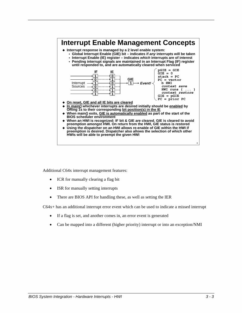
Interrupt Enable Management ConceptsInterrupt response is managed by a 2 level enable system:
Global Interrupt Enable (GIE) bit – indicates if any interrupts will be taken Interrupt Enable (IE) register – indicates which interrupts are of interest Pending interrupt signals are maintained in an Interrupt Flag (IF) registeruntil responded to, and are automatically cleared when serviced
On reset, GIE and all IE bits are clearedIn main() whichever interrupts are desired initially should be enabled by ORing 1s to their corresponding bit position(s) in the IEWhen main() exits, GIE is automatically enabled as part of the start of the BIOS scheduler environmentWhen an HWI is recognized: IF bit & GIE are cleared. GIE is cleared to avoid preemption amongst HWI. On return from the HWI, GIE status is restoredUsing the dispatcher on an HWI allows re-enable of GIE within the HWI if preemption is desired. Dispatcher also allows the selection of which other HWIs will be able to preempt the given HWI
101001
010111
1
IF IE
GIEInterruptSources
Event!
pGIE = GIEGIE = 0stack = PCPC = vectorb HWIcontext saveHWI runs { ... }context restore
GIE = pGIEPC = prior PC
6
Additional C64x interrupt management features:
• ICR for manually clearing a flag bit
• ISR for manually setting interrupts
• There are BIOS API for handling these, as well as setting the IER
C64x+ has an additional interrupt error event which can be used to indicate a missed interrupt
• If a flag is set, and another comes in, an error event is generated
• Can be mapped into a different (higher priority) interrupt or into an exception/NMI

Idle (IDL)
3 - 4 BIOS System Integration - Hardware Interrupts - HWI
Idle (IDL)
IdleIDL
Lowest priority - soft real-time - no deadlineIdle functions executes sequentiallyPriority at which real-time analysis is passed to host
Likely IDL ActivitiesLow power systems - idle the processorSystems in test - instrumentationUser interfacesDefragmentationGarbage collection
Return from main( )Inactive Ready RunningStarted
Resume
Preempted
8
Idle (IDL)
BIOS System Integration - Hardware Interrupts - HWI 3 - 5
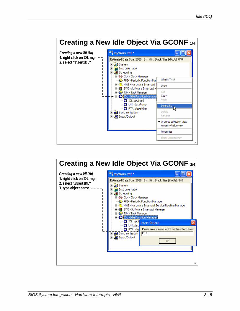
Creating a New Idle Object Via GCONF 1/4
Creating a new Idl Obj1. right click on IDL mgr2. select “Insert IDL”
9
Creating a new Idl Obj1. right click on IDL mgr2. select “insert IDL”
Creating a New Idle Object Via GCONF 2/4
Creating a new Idl Obj1. right click on IDL mgr2. select “Insert IDL”3. type object name
10
Idle (IDL)
3 - 6 BIOS System Integration - Hardware Interrupts - HWI
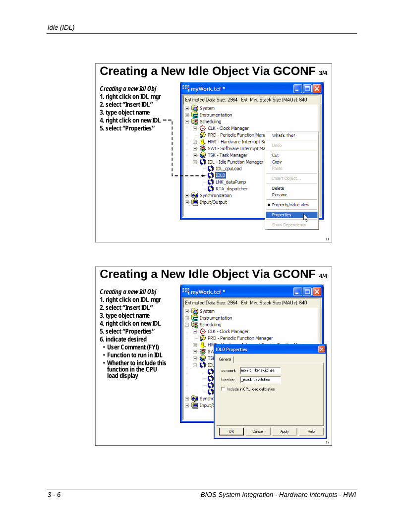
Creating a New Idle Object Via GCONF 3/4
Creating a new Idl Obj1. right click on IDL mgr2. select “Insert IDL”3. type object name4. right click on new IDL5. select “Properties”
11
Creating a new Idl Obj1. right click on IDL mgr2. select “insert IDL”3. right click on new IDL4. select “rename”5. type new name6. right click on new IDL7. select “properties”
Creating a New Idle Object Via GCONF 4/4
Creating a new Idl Obj1. right click on IDL mgr2. select “Insert IDL”3. type object name4. right click on new IDL5. select “Properties”6. indicate desired • User Comment (FYI)• Function to run in IDL• Whether to include this
function in the CPU load display
12

Hardware Interrupts (HWI)
BIOS System Integration - Hardware Interrupts - HWI 3 - 7
Hardware Interrupts (HWI) Hardware Interrupts
Much like “ISR”s (interrupt service routines)Vector table automatically renderedAdd interrupt keyword in front of function declarationContext switch (save/restore of state of CPU around the HWI on the system stack) automatically performed when interrupt keyword is usedAre a priority foreground activity that preempt background activity HWIs are taken in order of priorityDefault is one HWI does not preempt another: when a running HWI returns, then execution will pass to the highest priority HWI then available (or back to IDL if no HWI are flagged)
Foreground
Background
14
HWI_c (p1)HWI_c (p1)
HWI_a (p3)HWI_a (p3)
IDLIDL
HWI_b (p2)HWI_b (p2)
HWI Scheduling ExampleHighest Priority
Lowest Priority
LegendRunningReady
Any HWI will preempt IDLStandard practice is that no HWIs preempt any other running HWIOn return from an HWI, control is passed to highest pending HWIIs it always desirable to make high priority HWIs wait for lower priority HWIs to conclude before they are serviced?
time
1
1
1
2
2
2
12
Context SaveContext Restore
15
Hardware Interrupts (HWI)
3 - 8 BIOS System Integration - Hardware Interrupts - HWI
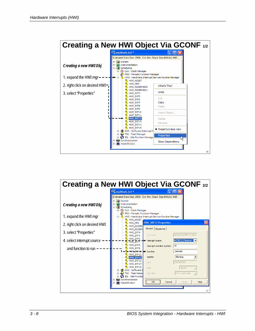
Creating a New HWI Object Via GCONF 1/2
Creating a new HWI Obj
3. select “Properties”
1. expand the HWI mgr
2. right click on desired HWI
16
Creating a New HWI Object Via GCONF 2/2
4. select interrupt source
and function to run
Creating a new HWI Obj
1. expand the HWI mgr
2. right click on desired HWI
3. select “Properties”
17

Interrupt Preemption
BIOS System Integration - Hardware Interrupts - HWI 3 - 9
Interrupt Preemption Adding Preemption to HWIs
When preemption amongst HWIs is desired, default HWI scheduling can be manually overriden
Developer can use the dispatcher in CCS to make any desired HWI preemptible
Preemption can be on all higher numbered HWIs, or on any selected group of higher or lower HWI
Adding the dispatcher increases context save and restore effort, some extra system overhead incurred
Use of the dispatcher requires removing the interrupt keyword in the function declaration
While seemingly desirable, HWI preemption will be seen to be only one of several scheduling options -handy in some cases, unneeded in others
19
HWI_c (p1)HWI_c (p1)
HWI_a (p3)HWI_a (p3)
IDLIDL
HWI_b (p2)HWI_b (p2)
Preemptive HWI Scheduling Example
RunningReady
Legend
Any HWI will preempt IDLHWI priority 3 does not preempt HWI priority 2HWI priority 1 preempts HWI priority 2note: if the dispatcher had been differently configured, HWI_acould have as easily preempted HWI_b, and HWI_c not so allowed
time
Highest Priority
Lowest Priority
20

Interrupt Preemption
3 - 10 BIOS System Integration - Hardware Interrupts - HWI
Enabling Preemption via the Dispatcher
Right click on an HWI and select the “properties” optionSelect the Dispatcher tab in the properties dialog boxCheck the Use Dispatcher boxSelect HWIs that will preempt this HWI via the Interrupt mask Option: Arg field allows an argument to be passed to the HWIBe sure to remove ‘interrupt’ keyword in front of ISR when using dispatcher ! !
To activate the dispatcher for a particular HWI:
21
Assembly Code Dispatch Option
myISR: HWI_enter ABMASK, CMASK, IEMASK, CCMASK...SWI_post(&mySwi);...HWI_exit ABMASK CMASK IERRESTOREMASK CCMASK
HWI_enter() and HWI_exit() are assembly macrosUse _enter at the start of an HWI and _exit at the end of the HWIAllows BIOS calls to be correctly invoked between the functions User specifies preemption by other HWIs (IEMASK)GIE enabled on _enter and restored on _exitUser specifies registers to save/restore (ABMASK, CMASK)User specifies cache control options (CCMASK)Cannot be used on HWIs that employ the BIOS dispatcher!Do not use interrupt keyword when using _enter and _exit !Usually use BIOS dispatcher, for final optimization consider _enter, _exit
stackA1A2...
CPUA1A2...Interrupt
preemption enabled here
22
Interrupt Preemption
BIOS System Integration - Hardware Interrupts - HWI 3 - 11
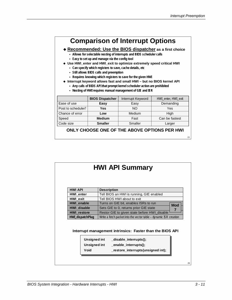
Comparison of Interrupt Options
YesNOYesPost to scheduler?
SmallerFast
Medium
Easy
LargerSmallerCode sizeCan be fastestMediumSpeed
Chance of error
Ease of use
Low
Easy
High
DemandingInterrupt KeywordBIOS Dispatcher HWI_enter, HWI_exit
Recommended: Use the BIOS dispatcher as a first choiceAllows for selectable nesting of interrupts and BIOS scheduler callsEasy to set up and manage via the config tool
Use HWI_enter and HWI_exit to optimize extremely speed critical HWICan specify which registers to save, cache details, etcStill allows BIOS calls and preemptionRequires knowing which registers to save for the given HWI
Interrupt keyword allows fast and small HWI – but no BIOS kernel APIAny calls of BIOS API that prompt kernel scheduler action are prohibitedNesting of HWI requires manual management of GIE and IER
ONLY CHOOSE ONE OF THE ABOVE OPTIONS PER HWI23
HWI API Summary
Tell BIOS HWI about to exitHWI_exitTell BIOS an HWI is running, GIE enabledHWI_enter
Restor GIE to given state before HWI_disableHWI_restoreSets GIE to 0, returns prior GIE stateHWI_disableTurns on GIE bit, enables ISRs to runHWI_enable
DescriptionHWI API
Write a fetch packet into the vector table – dynamic ISR creationHWI_dispatchPlug
Mod7
25
Interrupt management intrinsics: Faster than the BIOS API
Unsigned int _disable_interrupts();Unsigned int _enable_interrupts();Void _restore_interrupts(unsigned int);
Interrupt Monitor
3 - 12 BIOS System Integration - Hardware Interrupts - HWI
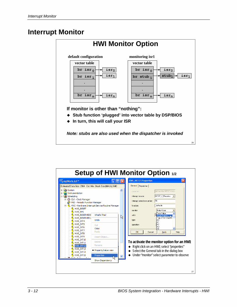
Interrupt Monitor HWI Monitor Option
If monitor is other than “nothing”:Stub function ‘plugged’ into vector table by DSP/BIOSIn turn, this will call your ISR
Note: stubs are also used when the dispatcher is invoked
default configurationvector table
br isr 0br isr 1
.
br isr n
.
isr0isr1
isrn
monitoring isr1vector table
br isr 0
.
br isr n
.
isr0
isrn
br stub 1isr1stub1
26
Setup of HWI Monitor Option 1/2
Right click on an HWI; select “properties”Select the General tab in the dialog boxUnder “monitor” select parameter to observe
To activate the monitor option for an HWI:
27
Interrupt Monitor
BIOS System Integration - Hardware Interrupts - HWI 3 - 13
Setup of HWI Monitor Option 2/2
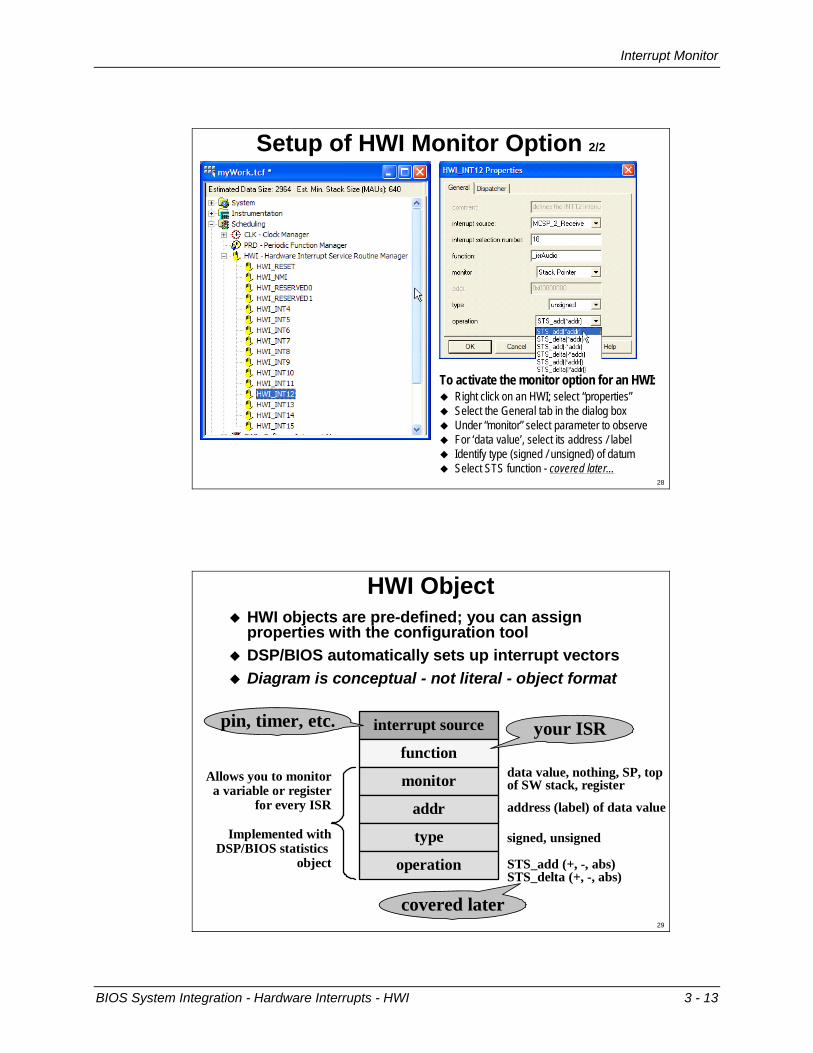
Right click on an HWI; select “properties”Select the General tab in the dialog boxUnder “monitor” select parameter to observeFor ‘data value’, select its address / labelIdentify type (signed / unsigned) of datumSelect STS function - covered later...
To activate the monitor option for an HWI:
28
HWI ObjectHWI objects are pre-defined; you can assign properties with the configuration toolDSP/BIOS automatically sets up interrupt vectorsDiagram is conceptual - not literal - object format
interrupt source
function
monitor
addr
type
operation
your ISRpin, timer, etc.
Allows you to monitora variable or register
for every ISR
Implemented withDSP/BIOS statistics
object
address (label) of data value
signed, unsigned
data value, nothing, SP, top of SW stack, register
STS_add (+, -, abs) STS_delta (+, -, abs)
covered later29
Lab 3: An HWI-Based System
3 - 14 BIOS System Integration - Hardware Interrupts - HWI
Lab 3: An HWI-Based System
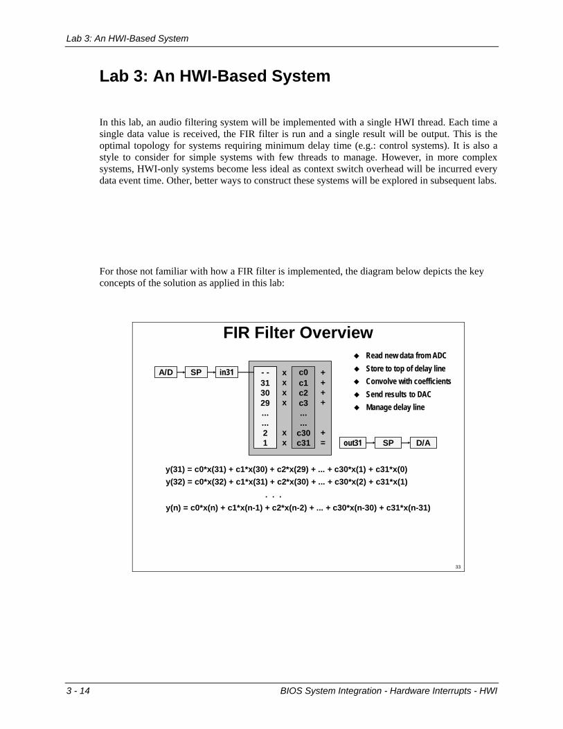
In this lab, an audio filtering system will be implemented with a single HWI thread. Each time a single data value is received, the FIR filter is run and a single result will be output. This is the optimal topology for systems requiring minimum delay time (e.g.: control systems). It is also a style to consider for simple systems with few threads to manage. However, in more complex systems, HWI-only systems become less ideal as context switch overhead will be incurred every data event time. Other, better ways to construct these systems will be explored in subsequent labs.
For those not familiar with how a FIR filter is implemented, the diagram below depicts the key concepts of the solution as applied in this lab:
c0c1c2c3......
c30c31
xxxx
xx
++++
+=
FIR Filter Overview
- -302928......10
Read new data from ADC
in31A/D SP
D/Aout31 SP
y(31) = c0*x(31) + c1*x(30) + c2*x(29) + ... + c30*x(1) + c31*x(0)
Manage delay lineSend results to DACConvolve with coefficients
31 Store to top of delay line- -313029......21
y(32) = c0*x(32) + c1*x(31) + c2*x(30) + ... + c30*x(2) + c31*x(1). . .
y(n) = c0*x(n) + c1*x(n-1) + c2*x(n-2) + ... + c30*x(n-30) + c31*x(n-31)
33

Lab 3: An HWI-Based System
BIOS System Integration - Hardware Interrupts - HWI 3 - 15
In this lab, you will: • create a CCS project • add the required source files to the project • create a BIOS configuration (.TCF) file from a given EVM6437 seed file • define the audio processing function as an HWI via GCONF • set the required build options • build, download, run, and debug the code on the EVM6437 • use a variety of CCS and BIOS debugging techniques to observe and interact with the code as
it runs on the DSP
You will also have the opportunity to study the function encapsulated by the HWI to review how the underlying code was constructed. As you will see, the code within the HWI is the code to solve the given problem. The thread type presented to BIOS allows it to be independently managed by the BIOS scheduler. In general, neither of these aspects need be concerned about the other.
In this workshop, the labs will share a consistent style. All labs were designed to be developed in a single directory: C:\BIOS\Labs\Work. Most labs build on the solution from the prior lab. Solutions to each lab are found in C:\BIOS\Sols\nn, where nn is the lab number. The solution folder for a prior lab can be used as a starting point for a given lab, or as a means of reviewing (rather than implementing) a given lab, if time and interest so dictate.
Audio Output
(48 KHz)
Lab 3: Hardware Interrupt - HWI
ADCAIC33
Audio Input
(48 KHz)McBSP
DRRFIR.c
FIR Code
DACAIC33
McBSPDXR
isrAudio
hist[0]=MCBSP_DRRif( sw0 == 1 )
dataOut=FIR(hist...)for (i = N-1; i >= 0; i--)
hist[i+1] = hist[i];else {dataOut=hist[0]}MCBSP_DXR = dataOut
mcbsp.c
coeffs.cCoefficients
BIOS\Labs\HW BIOS\Labs\Work BIOS\Labs\Algos
Create a new project, define build optionsAdd the components noted belowSet up a BIOS configuration, define the HWIBuild the project, download and debug on the EVMAdd an IDL object to monitor 2 EVM DIP switches
35

Lab 3: An HWI-Based System
3 - 16 BIOS System Integration - Hardware Interrupts - HWI
A. Project Creation Since the procedures for creating a project were already seen in the prior chapter, they are listed in a minimalized form here. If more detail is required in this section, refer back to the detailed instructions for these procedures in the prior lab, or ask the instructor for assistance.
1. Clear the contents of C:\BIOS\Labs\Work. Start CCS and connect to the EVM via Alt-C
2. Create a new project: Project | New • Project Name: myWork • Location: C:\BIOS\Labs\Work\ note: verify location directory before moving on!
3. Define the build options: Project | Build Options • Under Compiler, Basic, Target Version select: C64+ (mv6400+) • Under Compiler, Preprocessor, Include Search Path type:
..\HW; ..\Algos; $(BSL) and click OK
4. Add files to the project: • Copy audio-3.c from C:\BIOS\Labs\Algos to C:\BIOS\Labs\Work. Add the new
copy to the project. Double-click on audio-3.c in the project folders on the left CCS pane to open it onto the workspace to the right. Note the constructs pointed out in the code listing below.
• From C:\BIOS\Labs\Algos, add: fir.c and coeffs.c. The FIR algorithm is a simple sum-of-products implementation. For more information on coding and optimizing DSP algorithms, the C6000 Optimization Workshop may be of interest.
• From C:\BIOS\Labs\HW, add: codec.c. This file manages the serial port and data converter and is not of primary interest in this workshop. The soon to be released Driver Workshop and online documentation is the venue for this area of study.
• From C:\CCStudio_v3.3\boards\evmdm6437_v2\lib add the board support library evmdm6437bsl.lib to the project. Via this library a number of board specific operations can be performed, such as initializing the board, reading the DIP switches and controlling the LED lamps.
void isrAudio(void) {static short i; // loop indexstatic int dataIn, dataOut; // interface to MCBSP read/writestatic short dataOutL, dataOutR; // FIR results of L & R channels
dataIn = MCBSP1_DRR_32BIT; // Get one stereo sample (L & R Data)buf[0] = (short)dataIn; // Place Left data sample in delay linebuf[1] = (short)(dataIn >> 16); // Put Right data sample in delay line
for (i = FIRSZ-2; i >= 0; i--) // for 2*(#coeffs-1)buf[i+2] = buf[i]; // move all data down 1 pair
if( sw0 == 1 ) { // If filtering is on...fir(&buf[0], &coeffs[sw1][0], &dataOutL, FIRSZ, 1); // left channel FIRfir(&buf[1], &coeffs[sw1][0], &dataOutR, FIRSZ, 1); // right channel FIRdataOut = 0x0000FFFF & dataOutL; // get left value for outputdataOut |= 0xFFFF0000 & (dataOutR << 16); // or in right chan in MSBs
}else // if filtering is 'off'...
dataOut = dataIn; // new input copied to outputMCBSP1_DXR_32BIT = dataOut; // Send data to codec, (single channel)
}
FIR.cin \Algos
mcbsp.cin \HW
mcbsp.cin \HW
audio.c : HWI Function Encapsulation
36

Lab 3: An HWI-Based System
BIOS System Integration - Hardware Interrupts - HWI 3 - 17
B. TCF File Setup, HWI Definition, Project Build BIOS configuration (TCF) files define available target system hardware resources, how software sections are mapped to target memory, which BIOS objects to create in the system, and their configurations. Management of TCF files will be a significant part of this and succeeding labs.
1. Create a new TCF file: File | New | DSP/BIOS Configuration. Select the seed file ti.platforms.evmDM6437 and click OK. This file includes the hardware specifications of the EVM, such as the memory populated on the board.
2. To allow for dynamic allocations used in later labs, go to System | MEM – Memory Section Manager, right-click, select Properties, and uncheck No Dynamic Memory Heaps and click on the OK buttons. Assign some IRAM as a heap via System | Memory | IRAM, right-click, select Properties, and check create a heap in this memory and click OK. Finally, go back to System | MEM – Memory Section Manager | Properties and in the General tab specify IRAM in both Segment for… drop down windows.
3. Define an HWI to be managed by the BIOS scheduler: • Open the Scheduling folder and the HWI sub-folder • Right-click on HWI_INT4 and select Properties
− interrupt selection number : 51 − function: _isrAudio (the function in audio-3.c this HWI will call) − on the Dispatcher tab, check Use Dispatcher
4. Save the TCF file: File | Save As… as myWork.tcf in directory C:\BIOS\Labs\Work
5. Add myWork.tcf to the project. Note the automatic inclusion of two extra Generated Files.
6. In the Project View window, right click on myWork.tcf (in the DSP/BIOS Config folder) and select Compile File. Verify successful completion in the Output window.
7. Add the linker command file generated in the step above, myWorkcfg.cmd, to the project. In addition to the manually added CMD file, the inclusion of the TCF file automatically added the two Generated Files items, and two header files in the Include folder (visible once the project is built or you issue the command Project | Scan All File Dependencies).
8. Save the project: Project | Save
9. Verify that the Active Configuration display reads Debug (i.e.: not Release).
10. Build the project: Project | Build. A status window should open showing the files being created and indicating the success or problems encountered with each. If there are errors, try to determine and repair them, or call the instructor for assistance. Once the build is successfully completed, the code should automatically download. Verify that a yellow arrow, indicating the current PC (Program Counter) value, appears in audio-3.c at the beginning of the main function.
Lab 3: An HWI-Based System
3 - 18 BIOS System Integration - Hardware Interrupts - HWI
C. Project Run 1. Start an audio source playing on the PC, and verify the audio I/O cables are in place.
2. Run the project: F5, <alt>Debug | Run, or via the icon. Music should begin playing with normal (full range / no filter effect) sound quality.
3. Enable the filter function via a watch window variable: • Open a watch window via: View | Watch Window • In the newly opened watch window, click on the tab to “Watch 1” • Add sw0 to the watch list by selecting and dragging the variable from main.c to the
watch window • Click on the value (currently 0) of sw0 - it should then be highlighted in a blue 'edit
mode' color – and change the value to '1' and press 'enter'
The audio should sound distinctly 'murky' as all the high frequencies are now being filtered out. Try changing the enable back off and on again to verify this control and its use.
4. Control the coefficient set in use: Add the sw1 variable to the watch window as above. Try changing the value between 0, 1, and 2 which should select low-, high-, and all-pass filters, respectively.
5. Try out the use of graphical controls available in CCS as defined in a “GEL” file: • Load control.gel (gel subdirectory of labs folder) • Go to the CCS "GEL" menu, look for the FilterControl sub list, select each GEL there • The "On" slider controls the sw0 variable - slide the control up and down and note the
effect on the sound as well as the variable value in the watch window • The "Tone" slider allows the selection of Low-pass, High-pass, and All-pass filters.
Note the effect of this slider on the sw1 watch window variable value and the audio sound
6. Arrange the windows on the screen to make all key information visible.
7. Save this debug session configuration via: File | Workspace | Save Workspace As ... Use any name you like and save in the working directory C:\BIOS\Labs\WKS
8. Try loading a different workspace via: File | Workspace | Load Workspace ... From the dialog box, select: Lab-3.wks from c:\BIOS\Labs\WKS. Feel free to use the new one or recall your prior workspace.
9. Measure the load this lab presents to the DSP: Open the DSP/BIOS | CPU Load Graph window (or via icon: ). What load do you observe over a range of sw0 and coefficient values? Note your observations here: __________________________________________________________________________________________
10. Halt the execution of the code via: <shift>F5, <alt>Debug | Halt, or the icon.

Lab 3: An HWI-Based System
BIOS System Integration - Hardware Interrupts - HWI 3 - 19
D. Project Release Version Was this the range of CPU usage you would have predicted? Probably not - it seems quite high. Why was this so? The main factor is that code built in 'debug' configuration is not optimized. In this next section, building and measuring an optimized build of the code will be investigated.
1. Change the Active Configuration window from 'Debug' to Release
2. Define the release-version Project | Build Options ... (as per step A-3 above)
3. Build the Project. Wait for the code to download and the PC to arrive at main
4. Run the code. Enable the filter by using sw0 in the watch window and examine the new CPU load. How does this compare to what you observed in step C-9?
Note: This kind of performance improvement is not unusual. The use of optimization should be kept in mind as a key step in obtaining the maximum benefit of the DSP.
5. Halt the debugger.
E. Adding an IDL Thread When the DSP is not processing the HWI, it loops through a list of idle functions specified in the TCF file. These functions are serviced in succession as time permits. The code that allows BIOS data to be uploaded to the host PC during debug resides in some of these IDL threads. Users can add any additional functions desired to the IDL thread. In this case, the ability to read the settings of DIP switches 1 and 2 on the EVM and have their settings control the sw0 and sw1 variables will be added. The code to implement the reading of the switches is already written. In this lab, the goal will be to integrate the function into the project as a new IDL object.
1. Add the file dipMonitor.c (in the HW directory) to the project.
2. Open the dipMonitor.c file and review the code briefly. Note the convenience of the BSL (Board Support Library) I2C functions and how they are used here to read the DIP switches of the EVM board.
3. Create an IDL object in the TCF file. Right click on the IDL Function Manager and select Insert IDL. Give the new IDL object a name of your choosing.
4. Associate the readDipSwitches() function with the new IDL object: Right click on the new IDL object, select Properties and enter _readDipSwitches in the function field.
Hint: It is important that the tag “readDipSwitches” is preceded by an underscore symbol to denote that it is a C-generated function as opposed to an assembly function. C functions are renamed with a preceding underscore by the C compiler, and failure to include this in the tag will cause an error at the linker stage of the projet build.

Lab 3: An HWI-Based System
3 - 20 BIOS System Integration - Hardware Interrupts - HWI
5. Add a call to the initDipSwitches() function to main(). This function simply initializes the variables used in the readDipSwitches function. In general, BIOS based systems often place initialization functions in main()
6. Add "dipMonitor.h" to the list of inclusions at the top of audio-3.c.
7. Build, load, and run the project.
8. Verify the correct operation of switch 0 and switch 1
Switch 0 should toggle the sw0 and switch 1 select between the LPF and HPF. Note also that the GEL sliders and watch values also allow these control. The readDipSwitches() function was written to only have effect when the DIP switch is changed, thus allowing manual debug changes to also be effective.
9. Save the completed project Project | Save
10. If desired, note again the CPU loads.
Have they changed significantly from prior observation?
11. Halt the debugger.
F. Save Completed Lab Exercise Using windows explorer, create a new folder named 03 in c:\BIOS\mySols and copy all files from C:\BIOS\Labs\Work into this new folder.
Note: When re-running saved projects, move the saved directory back under the C:\BIOS\Labs directory, so as to keep the relative locations for the files in the Algos, HW and other directories consistent to their original state. Incremental work could have been saved in folders under the Labs directory directly, but the choice to place them under the mySols directory was made so as to reduce ‘clutter’ in the main Labs folder during the class.
G. Optional Activities Time permitting, feel free to examine any code elements of interest, or to try out any code changes you like to lab03.c. Avoid changing fir.c or any of the HW directory files, as these will be needed in their current state in later labs, and are not really a relevant part of the study of BIOS anyway. Suggestion: you may wish to restore the solution just saved in directory 03 back into the work directory as a more reliable starting point for the next lab once you are through with any further experimentation.