Embed Size (px)
Citation preview

Hardware Installation Manual forEM Series Stepper Drives
www.leadshine.com
HWMN‐EM‐R20111018

ii
Leadshine reserves the right to make changes without further notice to any products
herein to improve reliability, function or design. Leadshine does not assume any
liability arising out of the application or use of any product or circuit described
herein; neither does it convey any license under its patent rights of others.
Leadshine’s general policy does not recommend the use of its products in life
support or aircraft applications wherein a failure or malfunction of the product may
directly threaten life or injury. According to Leadshine’s terms and conditions of
sales, the user of Leadshine’s products in life support or aircraft applications
assumes all risks of such use and indemnifies Leadshine against all damages.
©2011 by Leadshine Technology, All Rights Reserved
Change Log
Revision Date Changes Version
2011-10-18 Original Create MN-EM-R20111018
HWMN‐EM‐R20111018

iii
Safety Items
!Notice
Read this manual carefully before trying to install the stepper drive into your system. The person
setup the stepper drive should have a better understanding on electronics and mechanics. Contact
Leadshine technical guys when have questions on this document.
!Caution
Make sure the power supply voltage dose not exceed the drive’s input range. Double check the
connections and make sure the power lead polarity is correct.
!Warning
Do not set high current to small stepper motor. It is possible that the motor will be damaged.
!Caution
Disconnect the motor from the load if you are not sure the move direction. Adjust the axis in the
middle before trying to run the motor.
!Warning
Never disconnect the motor lead when the power source is energized.
HWMN‐EM‐R20111018

iv
Table of Contents
1. Family Overview......................................................................................................................................................... 1
Introduction ............................................................................................................................................................. 1
.Product Covered..................................................................................................................................................... 1
2-phase EM Stepper Drives............................................................................................................................. 1
3-phase EM Stepper Drives............................................................................................................................. 1
Mechanical Specifications....................................................................................................................................... 2
Elimination of Heat ................................................................................................................................................. 3
3. Connectors and Pin Assignment.................................................................................................................................. 3
4. Control Signal Requirement........................................................................................................................................ 4
Signal Mode and Sequence Chart ........................................................................................................................... 4
5. Connecting Control Signal .......................................................................................................................................... 5
NPN Signal Connections......................................................................................................................................... 5
PNP Signal Connections.......................................................................................................................................... 5
Differential Signal Connections .............................................................................................................................. 5
6. Connecting the Motor.................................................................................................................................................. 6
2-phase, 4-lead Motors Connections ....................................................................................................................... 6
2 phase, 6-lead Motors Connections ....................................................................................................................... 6
Half Coil Configurations ................................................................................................................................. 6
Full Coil Configurations.................................................................................................................................. 6
2 phase, 8-lead Motors Connections ....................................................................................................................... 7
Series Connections .......................................................................................................................................... 7
Parallel Connections........................................................................................................................................ 7
3 phase Motors Connections ................................................................................................................................... 7
Matching Stepper Motors ........................................................................................................................................ 8
7. Power Supply Selection .............................................................................................................................................. 9
Regulated or Unregulated Power Supply ................................................................................................................ 9
Multiple Drives ....................................................................................................................................................... 9
Selecting Supply Voltage......................................................................................................................................... 9
Recommended Supply Voltage...................................................................................................................... 10
8. Typical Connections .................................................................................................................................................. 10
9. Wiring Notes ............................................................................................................................................................. 11
10. Configuring the Drive ............................................................................................................................................. 12
Introduction ........................................................................................................................................................... 12
Configuration Procedure ....................................................................................................................................... 13
Select motor........................................................................................................................................................... 13
Auto Configuration ............................................................................................................................................... 13
Microstep Resolution Selection............................................................................................................................. 14
Current Settings..................................................................................................................................................... 14
Dynamic current setting ................................................................................................................................ 14
Idle current setting......................................................................................................................................... 14
HWMN‐EM‐R20111018

v
HWMN‐EM‐R20111018
11. Protection Functions................................................................................................................................................ 15
Over-current Protection ................................................................................................................................. 15
Over-voltage Protection................................................................................................................................. 15
Sensorless Stall Protection ............................................................................................................................ 15
Protection Indications.................................................................................................................................... 15
12. Frequently Asked Questions.................................................................................................................................... 16
Problem Symptoms and Possible Causes .............................................................................................................. 16
Appendix ....................................................................................................................................................................... 17
Speed To rque Curves for Pre-Matching Leadshine Motors ................................................................................. 17
Twelve Month Limited Warranty .......................................................................................................................... 18
Exclusions ..................................................................................................................................................... 18
Obtaining Warranty Service .......................................................................................................................... 18
Warranty Limitations..................................................................................................................................... 18
Shipping Failed Product ................................................................................................................................ 18
Contact Us..................................................................................................................................................................... 19
EM Series Drive Hardware Installation Manual
1. Family Overview
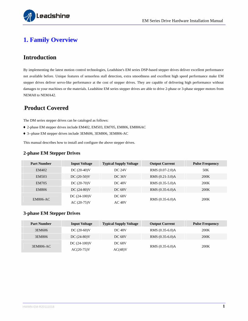
Introduction
By implementing the latest motion control technologies, Leadshine's EM series DSP-based stepper drives deliver excellent performance
not available before. Unique features of sensorless stall detection, extra smoothness and excellent high speed performance make EM
stepper drives deliver servo-like performance at the cost of stepper drives. They are capable of delivering high performance without
damages to your machines or the materials. Leadshine EM series stepper drives are able to drive 2-phase or 3-phase stepper motors from
NEMA8 to NEMA42.
.Product Covered
The DM series stepper drives can be cataloged as follows:
2-phase EM stepper drives include EM402, EM503, EM705, EM806, EM806AC
3--phase EM stepper drives include 3EM606, 3EM806, 3EM806-AC
This manual describes how to install and configure the above stepper drives.
2-phase EM Stepper Drives
Part Number Input Voltage Typical Supply Voltage Output Current Pulse Frequency
EM402 DC (20-40)V DC 24V RMS (0.07-2.0)A 50K
EM503 DC (20-50)V DC 36V RMS (0.21-3.0)A 200K
EM705 DC (20-70)V DC 48V RMS (0.35-5.0)A 200K
EM806 DC (24-80)V DC 68V RMS (0.35-6.0)A 200K
EM806-AC DC (24-100)V
AC (20-75)V
DC 68V
AC 48V RMS (0.35-6.0)A 200K
3-phase EM Stepper Drives
Part Number Input Voltage Typical Supply Voltage Output Current Pulse Frequency
3EM606 DC (20-60)V DC 48V RMS (0.35-6.0)A 200K
3EM806 DC (24-80)V DC 68V RMS (0.35-6.0)A 200K
3EM806-AC DC (24-100)V
AC(20-75)V
DC 68V
AC(48)V RMS (0.35-6.0)A 200K
1 HWMN-EM-R20111018

EM Series Drive Hardware Installation Manual
Mechanical Specifications
EM402 EM503
EM705, 3EM606 EM806, 3EM806
EM806-AC, 3EM806-AC
2 HWMN-EM-R20111018

EM Series Drive Hardware Installation Manual
Elimination of Heat
Drive’s reliable working temperature(heat sink) should be <70℃(158℉), and motor working temperature(surface) should be
<80℃(176℉);
It is recommended to use automatic idle-current mode, namely current automatically reduce to 60% when motor stops, so as to
reduce driver heating and motor heating;
It is recommended to mount the driver vertically to maximize heat sink area. Use forced cooling method to cool the system if
necessary.
3. Connectors and Pin Assignment
The EM stepper drives have two connectors, connector for control signals connections and connector for power and motor connections.
Most EM drives adopt screw terminals for signal and power connections as follows. The following figure is connectors and pin
assignment of EM806. The other EM drives have similar interface. Please refer to drive’s datasheet for the detail.
3 HWMN-EM-R20111018

EM Series Drive Hardware Installation Manual
4. Control Signal Requirement
Signal Mode and Sequence Chart
Most EM drive can support Pulse/Direction and CW/CCW control signal modes. In order to avoid some fault operations and deviations,
PUL, DIR and ENA should abide by some rules, shown as following diagram:
Remark:
a) ENA must be ahead of DIR by at least 5us. Usually, ENA+ and ENA- are NC (not connected).
b) DIR must be ahead of PUL active edge by 5us to ensure correct direction;
c) Pulse width not less than t3;
d) Low level width not less than t4.
Model t3 t4 Model t3 t4
EM402 10 us 10 us EM806-AC 2.5 us 2.5 us
EM503 2.5 us 2.5 us 3EM606 2.5 us 2.5 us
EM705 2.5 us 2.5 us 3EM806 2.5 us 2.5 us
EM806 2.5 us 2.5 us 3EM806-AC 2.5 us 2.5 us
4 HWMN-EM-R20111018

EM Series Drive Hardware Installation Manual
5. Connecting Control Signal
Most of the EM stepper drives can accept both differential and single-ended inputs (including open-collector and PNP output). Some
only accept the single-ended inputs due to space limit
NPN Signal Connections
DriveController
VCC
PUL-
PUL+
ENA-
R=0 if VCC=5V; R=1K(Power>0.125W) if VCC=12V; R=2K(Power>0.125W) if VCC=24V; R must be connected to control signal terminal.
R
R
R
PUL
DIR
ENABLE
DIR-
DIR+
ENA+
PNP Signal Connections
DriveController
VCC PUL-
PUL+
ENA-
R=0 if VCC=5V; R=1K(Power>0.125W) if VCC=12V; R=2K(Power>0.125W) if VCC=24V; R must be connected to control signal terminal.
RPUL
DIR
ENABLE
DIR-
DIR+
ENA+
R
R
Differential Signal Connections
DriveController
PUL-
PUL+
ENA-
R=0 if VCC=5V; R=1K(Power>0.125W) if VCC=12V; R=2K(Power>0.125W) if VCC=24V; R must be connected to control signal terminal.
R
DIR-
DIR+
ENA+
R
R
PUL-
PUL+
ENA-
DIR-
DIR+
ENA+
5 HWMN-EM-R20111018
EM Series Drive Hardware Installation Manual
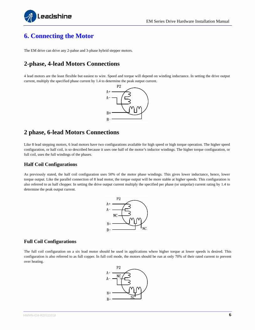
6. Connecting the Motor
The EM drive can drive any 2-pahse and 3-phase hybrid stepper motors.
2-phase, 4-lead Motors Connections
4 lead motors are the least flexible but easiest to wire. Speed and torque will depend on winding inductance. In setting the drive output current, multiply the specified phase current by 1.4 to determine the peak output current.
2 phase, 6-lead Motors Connections
Like 8 lead stepping motors, 6 lead motors have two configurations available for high speed or high torque operation. The higher speed configuration, or half coil, is so described because it uses one half of the motor’s inductor windings. The higher torque configuration, or full coil, uses the full windings of the phases.
Half Coil Configurations
As previously stated, the half coil configuration uses 50% of the motor phase windings. This gives lower inductance, hence, lower torque output. Like the parallel connection of 8 lead motor, the torque output will be more stable at higher speeds. This configuration is also referred to as half chopper. In setting the drive output current multiply the specified per phase (or unipolar) current rating by 1.4 to determine the peak output current.
Full Coil Configurations
The full coil configuration on a six lead motor should be used in applications where higher torque at lower speeds is desired. This configuration is also referred to as full copper. In full coil mode, the motors should be run at only 70% of their rated current to prevent over heating.
6 HWMN-EM-R20111018
EM Series Drive Hardware Installation Manual
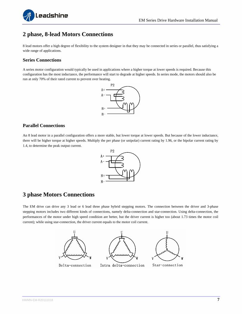
2 phase, 8-lead Motors Connections
8 lead motors offer a high degree of flexibility to the system designer in that they may be connected in series or parallel, thus satisfying a wide range of applications.
Series Connections
A series motor configuration would typically be used in applications where a higher torque at lower speeds is required. Because this configuration has the most inductance, the performance will start to degrade at higher speeds. In series mode, the motors should also be run at only 70% of their rated current to prevent over heating.
Parallel Connections
An 8 lead motor in a parallel configuration offers a more stable, but lower torque at lower speeds. But because of the lower inductance,
there will be higher torque at higher speeds. Multiply the per phase (or unipolar) current rating by 1.96, or the bipolar current rating by
1.4, to determine the peak output current.
3 phase Motors Connections
The EM drive can drive any 3 lead or 6 lead three phase hybrid stepping motors. The connection between the driver and 3-phase
stepping motors includes two different kinds of connections, namely delta-connection and star-connection. Using delta-connection, the
performances of the motor under high speed condition are better, but the driver current is higher too (about 1.73 times the motor coil
current); while using star-connection, the driver current equals to the motor coil current.
7 HWMN-EM-R20111018

EM Series Drive Hardware Installation Manual
Matching Stepper Motors
Minimum Motor Size Typical Motor Size Maximum Motor Size Leadshine Stepper Motors
EM402 NEMA 8 NEMA 17 MEMA 23 35HS01, 39HS02, 42HS02, , 42HS03
EM503 NEMA 14 NEMA 23 MEMA 23 57HS04, 57HS09, 57HS13, 57HS22
EM705 NEMA 17 NEMA 23 MEMA 34 57HS22, 86HS35, 86HS45
EM806 NEMA 23 NEMA 34 NEMA 34 86HS35, 86HS45, 86HS85
EM806-AC NEMA 23 NEMA 34 NEAM 42 86HS45, 86HS85, 110HS12
3EM606 NEMA 17 NEMA 23 NEMA 23 573S09, 573S15
3EM806 NEMA 23 NEMA 34 NEMA 34 573S22, 573S42
3EM806-AC NEMA 23 NEMA 34 NEMA 42 573S42, 573S68H
8 HWMN-EM-R20111018

EM Series Drive Hardware Installation Manual
7. Power Supply Selection
The DM drive can match medium and small size stepping motors (from NEMA frame size 8 to 34) made by Leadshine or other motor
manufactures around the world. To achieve good driving performances, it is important to select supply voltage and output current
properly. Generally speaking, supply voltage determines the high speed performance of the motor, while output current determines the
output torque of the driven motor (particularly at lower speed). Higher supply voltage will allow higher motor speed to be achieved, at
the price of more noise and heating. If the motion speed requirement is low, it’s better to use lower supply voltage to decrease noise,
heating and improve reliability.
Regulated or Unregulated Power Supply
Both regulated and unregulated power supplies can be used to supply the drive. However, unregulated power supplies are preferred due
to their ability to withstand current surge. If regulated power supplies (such as most switching supplies.) are indeed used, it is important
to have large current output rating to avoid problems like current clamp, for example using 4A supply for 3A motor-drive operation. On
the other hand, if unregulated supply is used, one may use a power supply of lower current rating than that of motor (typically 50%~
70% of motor current). The reason is that the drive draws current from the power supply capacitor of the unregulated supply only during
the ON duration of the PWM cycle, but not during the OFF duration. Therefore, the average current withdrawn from power supply is
considerably less than motor current. For example, two 3A motors can be well supplied by one power supply of 4A rating.
Multiple Drives
It is recommended to have multiple drives to share one power supply to reduce cost, if the supply has enough capacity. To avoid cross
interference, DO NOT daisy-chain the power supply input pins of the drives. Instead, please connect them to power supply separately.
Selecting Supply Voltage
The power MOSFETS inside the EM drive can actually operate with wider voltage range than the input specification. Higher supply
voltage can increase motor torque at higher speeds, thus helpful for avoiding losing steps. However, higher voltage may cause bigger
motor vibration at lower speed, and it may also cause over-voltage protection or even drive damage. Therefore, it is suggested to choose
only sufficiently high supply voltage for intended applications, and it is suggested to use power supplies with theoretical output voltage
of drive’s minimum + 10% to drive’s maximum – 10%, leaving room for power fluctuation and back-EMF.
Driver Input Voltage
Driver Upper Input limit
Power Supply Voltage
HeatingVibration
Maximum Safe RatingDriver Upper Input limit – 10%
Driver Lower Input limit + 10%
Driver Lower Input limit
Minimum Safe Rating
TorqueSpeed
Safe Region
Driver Input Voltage
Driver Upper Input limit
Power Supply Voltage
HeatingVibration
Maximum Safe RatingDriver Upper Input limit – 10%
Driver Lower Input limit + 10%
Driver Lower Input limit
Minimum Safe Rating
TorqueSpeed
Safe Region
9 HWMN-EM-R20111018
EM Series Drive Hardware Installation Manual
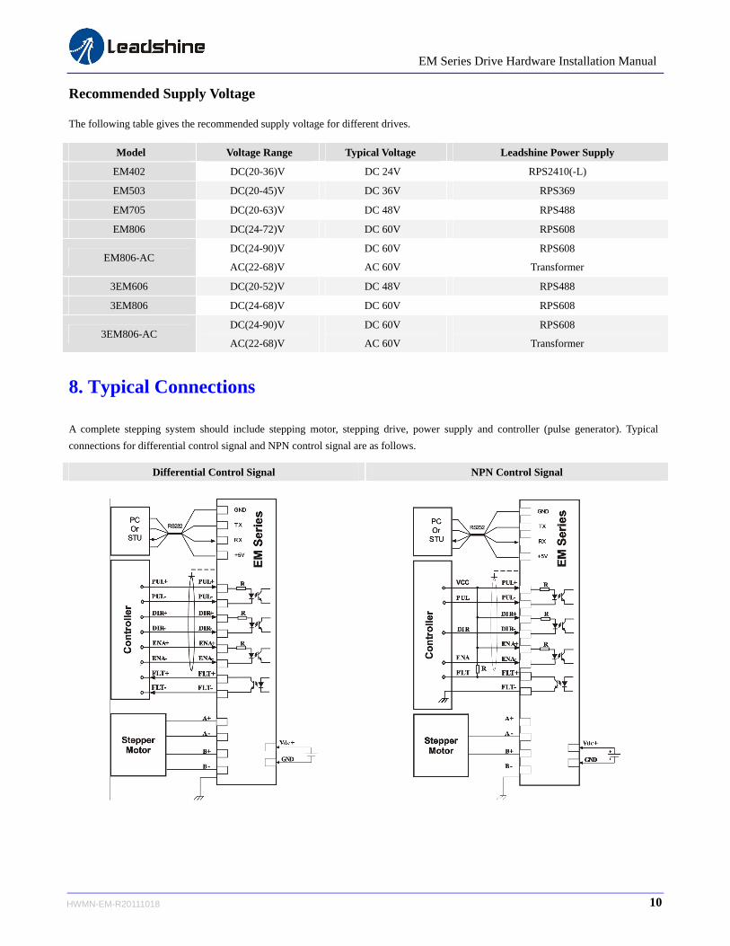
Recommended Supply Voltage
The following table gives the recommended supply voltage for different drives.
Model Voltage Range Typical Voltage Leadshine Power Supply
EM402 DC(20-36)V DC 24V RPS2410(-L)
EM503 DC(20-45)V DC 36V RPS369
EM705 DC(20-63)V DC 48V RPS488
EM806 DC(24-72)V DC 60V RPS608
EM806-AC DC(24-90)V
AC(22-68)V
DC 60V
AC 60V
RPS608
Transformer
3EM606 DC(20-52)V DC 48V RPS488
3EM806 DC(24-68)V DC 60V RPS608
3EM806-AC DC(24-90)V
AC(22-68)V
DC 60V
AC 60V
RPS608
Transformer
8. Typical Connections
A complete stepping system should include stepping motor, stepping drive, power supply and controller (pulse generator). Typical
connections for differential control signal and NPN control signal are as follows.
Differential Control Signal NPN Control Signal
10 HWMN-EM-R20111018

EM Series Drive Hardware Installation Manual
9. Wiring Notes
In order to improve anti-interference performance of the drive, it is recommended to use twisted pair shield cable.
To prevent noise incurred in PUL/DIR signal, pulse/direction signal wires and motor wires should not be tied up together. It is
better to separate them by at least 10 cm, otherwise the disturbing signals generated by motor will easily disturb pulse direction
signals, causing motor position error, system instability and other failures.
If a power supply serves several drives, separately connecting the drives is recommended instead of daisy-chaining.
It is prohibited to pull and plug power connector while the drive is powered ON, because there is high current flowing through
motor coils (even when motor is at standstill). Pulling or plugging power connector with power on will cause extremely high
back-EMF voltage surge, which may damage the drive.
11 HWMN-EM-R20111018
EM Series Drive Hardware Installation Manual
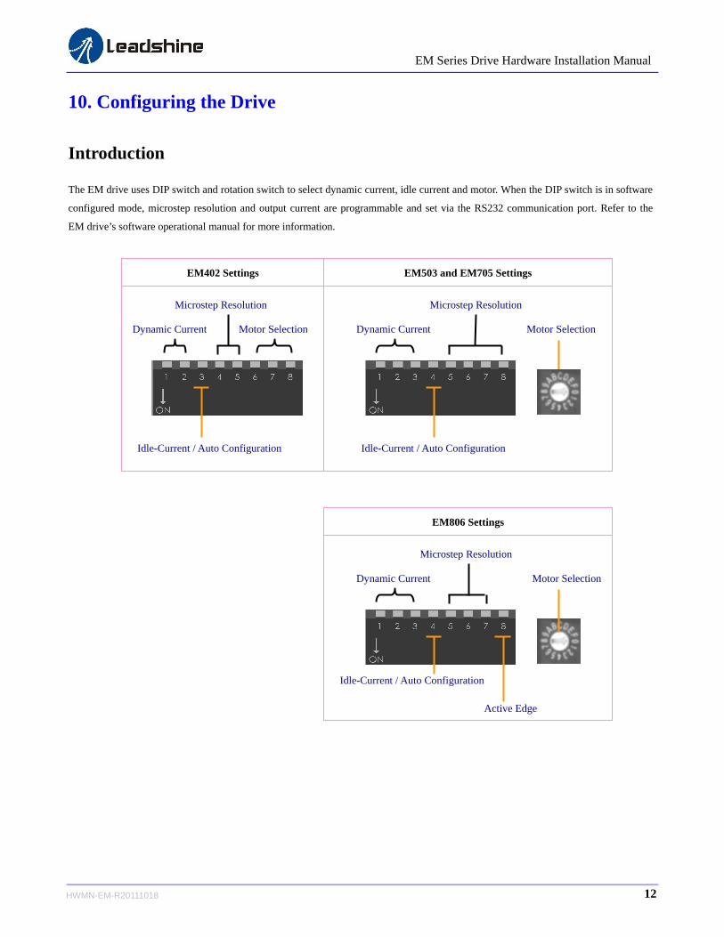
10. Configuring the Drive
Introduction
The EM drive uses DIP switch and rotation switch to select dynamic current, idle current and motor. When the DIP switch is in software
configured mode, microstep resolution and output current are programmable and set via the RS232 communication port. Refer to the
EM drive’s software operational manual for more information.
Motor SelectionDynamic Current
Microstep Resolution
Idle-Current / Auto Configuration
Dynamic Current
Microstep Resolution
Idle-Current / Auto Configuration
Motor Selection
EM402 Settings EM503 and EM705 Settings
Dynamic Current
Microstep Resolution
Idle-Current / Auto Configuration
Motor Selection
Active Edge
EM806 Settings
12 HWMN-EM-R20111018
EM Series Drive Hardware Installation Manual
13 HWMN-EM-R20111018
Configuration Procedure
If it is the first time installation and the EM drive works together with pre-matching Leadshine stepper motor, you can follow the steps
below to configure the EM series stepper drive:
Set the rotation switch according to the motor
Select the microstep resolution according to the application and the control system
Select the dynamic current and idle current according to the motor and the application
Test the drive in your system
If it is the first time installation and the EM drive works together with the motor from other manufacturer, you can follow the steps
below to configure the EM series stepper drive:
Set the rotation switch to one of the custom position
Select the microstep resolution according to the application and the control system
Select the dynamic current and idle current according to the motor and the application
Apply power to the EM drive and activate EM drive’s Auto-configuration
Test the drive in your system
Selecting Motor
For pre-matching Leadshine stepper motors, the EM drive has been tuned and the corresponding parameters have been stored in the
nonvolatile memory. The user can select the motor via DIP switch (EM402) or rotation switch (other drivers) according to the motor
selection table in the drive cover.
The EM drive also offers Auto-configuration for non-leadshine stepper motors. The user needs to select one of the custom positions in
the motor selection table. See more detail below.
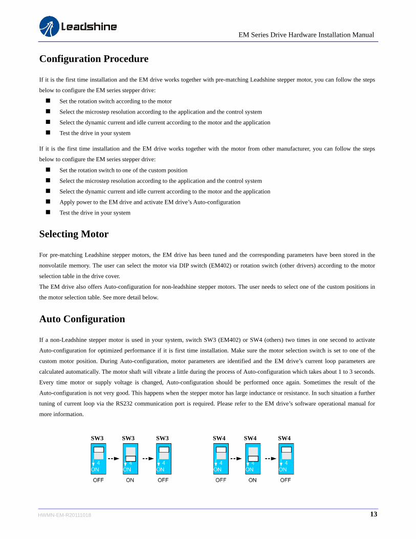
Auto Configuration
If a non-Leadshine stepper motor is used in your system, switch SW3 (EM402) or SW4 (others) two times in one second to activate
Auto-configuration for optimized performance if it is first time installation. Make sure the motor selection switch is set to one of the
custom motor position. During Auto-configuration, motor parameters are identified and the EM drive’s current loop parameters are
calculated automatically. The motor shaft will vibrate a little during the process of Auto-configuration which takes about 1 to 3 seconds.
Every time motor or supply voltage is changed, Auto-configuration should be performed once again. Sometimes the result of the
Auto-configuration is not very good. This happens when the stepper motor has large inductance or resistance. In such situation a further
tuning of current loop via the RS232 communication port is required. Please refer to the EM drive’s software operational manual for
more information.
SW3 SW3 SW3 SW4 SW4 SW4

EM Series Drive Hardware Installation Manual
Microstep Resolution Selection
The stepper motor moves one step when one pulse is applied to the stepper drive. If microstep is 1, the step angle is a full step which is
1.8 degree for 2-phase stepper motor and 1.2 degree for 3-hpase stepper motor. Microstep can be taken as the divisions of one full step.
For example, stepper motor moves half of the full step when the microstep is 2. For 2-phase stepper motor and drive, we have the
following formula to calculate the microstep resolution, or pulse counts of one motor shaft revolution:
MicrostepsolutionMicrostep 200Re
The motor speed can be calculated as follows:
solutionMicrostep
FrequencyInputPulseRPSSpeedMotor
Re
)(
When selecting the drive’s microstep resolution for the system:
Consider the MAX speed needed, MAX input frequency of driver and MAX output frequency of the controller.
1600 pulses/revolution (8 Microstep) is suitable for most application.
>1600 pulses/revolution only increase smoothness but not resolution.
For digital driver, Microstep resolution is not important.
Current Settings
Dynamic Current Setting
For a given motor, higher drive current will make the motor to output more torque, but at the same time causes more heating in the
motor and drive. Therefore, output current is generally set to be such that the motor will not overheat for long time operation. Since
parallel and serial connections of motor coils will significantly change resulting inductance and resistance, it is therefore important to set
drive output current depending on motor phase current, motor leads and connection methods. Phase current rating supplied by motor
manufacturer is important in selecting drive current, however the selection also depends on leads and connections.
Idle Current Setting
When there is no pulse applied to the EM drive and the time exceeds the idle-time which can be configured via the PC based software,
the drive goes into idle state. SW3 (EM402) or SW4 (others) is used to set the idle-current, OFF meaning that the motor coil current is
automatic reduced, and ON meaning that current is the same as the selected dynamic current.
By default, the current automatically reduced to 60% of the selected dynamic current two second after the last pulse. Theoretically, this
will reduce motor heating to 36% (due to P=I2*R) of the original value. If the user wants to change the idle time and current reduction
rate, please refer to EM drive’s software operational manual.
14 HWMN-EM-R20111018

EM Series Drive Hardware Installation Manual
11. Protection Functions
To improve reliability, the EM drive incorporates some built-in protection functions. The DM drive uses one red LED to indicate
what protection has been activated. The periodic time of red is 3 s (seconds), and how many times the red LED blinks indicates what
protection has been activated. Because only one protection can be displayed by red LED, so the drive will decide what error to
display according to their priorities. See the following Protection Indications table for displaying priorities.
Over-current Protection
Over-current protection will be activated when continuous current exceeds the limit or in case of short circuit between motor coils or
between motor coil and ground, and RED LED will blink once within each periodic time.
Over-voltage Protection
When power supply voltage exceeds the limit, protection will be activated and red LED will blink twice within each periodic time.
Sensorless Stall Protection
By detecting motor voltage, current, and back-EMF signal, EM series drives can detect loss-of-synchronization of stepper motors
without encoders. When the detection is activated, red LED will blink five times within each periodic time.
Note:
When above protections are active, the motor shaft will be free or the LED will blink. Reset the drive by repowering it to make it
function properly after removing above problems. For sensorless stall protection, you can also clear the error in ProTuner. See drive’s
software operational manual for more information.
Since there is no protection against power leads (﹢,﹣) reversal, it is critical to make sure that power supply leads correctly connected
to drive. Otherwise, the drive will be damaged instantly.
Protection Indications
Priority Time(s) of Blink Sequence wave of RED LED Description
1st 1 0.2S
3S
Over-current protection
2nd 2 0.2S 0.3S
3S
Over-voltage protection
3rd 5 0.2S 0.3S
3S
Senssorless Stall Protection
15 HWMN-EM-R20111018

EM Series Drive Hardware Installation Manual
12. Frequently Asked Questions
In the event that your drive doesn’t operate properly, the first step is to identify whether the problem is electrical or mechanical in nature.
The next step is to isolate the system component that is causing the problem. As part of this process you may have to disconnect the
individual components that make up your system and verify that they operate independently. It is important to document each step in the
troubleshooting process. You may need this documentation to refer back to at a later date, and these details will greatly assist our
Technical Support staff in determining the problem should you need assistance.
Many of the problems that affect motion control systems can be traced to electrical noise, controller software errors, or mistake in
wiring.
Problem Symptoms and Possible Causes
Symptoms Possible Problems
No power
Microstep resolution setting is wrong
DIP switch current setting is wrong
Fault condition exists
Motor is not rotating
The drive is disabled
Motor rotates in the wrong direction Motor phases may be connected in reverse
DIP switch current setting is wrong The drive in fault
Something wrong with motor coil
Control signal is too weak
Control signal is interfered
Wrong motor connection
Something wrong with motor coil
Erratic motor motion
Current setting is too small, losing steps
Current setting is too small
Motor is undersized for the application
Acceleration is set too high Motor stalls during acceleration
Power supply voltage too low
Inadequate heat sinking / cooling
Automatic current reduction function not being utilized Excessive motor and drive heating
Current is set too high
16 HWMN-EM-R20111018
EM Series Drive Hardware Installation Manual
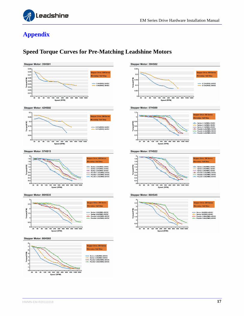
Appendix
Speed Torque Curves for Pre-Matching Leadshine Motors
17 HWMN-EM-R20111018

EM Series Drive Hardware Installation Manual
Twelve Month Limited Warranty
Leadshine Technology Co., Ltd. warrants its products against defects in materials and workmanship for a period of 12 months from shipment out of factory. During the warranty period, Leadshine will either, at its option, repair or replace products which proved to be defective.
Exclusions
The above warranty does not extend to any product damaged by reasons of improper or inadequate handlings by customer, improper or inadequate customer wirings, unauthorized modification or misuse, or operation beyond the electrical specifications of the product and/or operation beyond environmental specifications for the product.
Obtaining Warranty Service
To obtain warranty service, a returned material authorization number (RMA) must be obtained from customer service at e-mail: before returning product for service. Customer shall prepay shipping charges for products returned to Leadshine for warranty service, and Leadshine shall pay for return of products to customer.
Warranty Limitations
Leadshine makes no other warranty, either expressed or implied, with respect to the product. Leadshine specifically disclaims the implied warranties of merchantability and fitness for a particular purpose. Some jurisdictions do not allow limitations on how long and implied warranty lasts, so the above limitation or exclusion may not apply to you. However, any implied warranty of merchantability or fitness is limited to the 12-month duration of this written warranty.
Shipping Failed Product
If your product fail during the warranty period, e-mail customer service at to obtain a returned material authorization number (RMA)
before returning product for service. Please include a written description of the problem along with contact name and address. Send
failed product to distributor in your area or: Leadshine Technology Co., Ltd. 3/F, Block 2, Nanyou Tianan Industrial Park, Nanshan Dist,
Shenzhen, China. Also enclose information regarding the circumstances prior to product failure.
18 HWMN-EM-R20111018

EM Series Drive Hardware Installation Manual
19 HWMN-EM-R20111018
Contact Us
China Headquarters
Address: 3/F, Block 2, Nanyou Tianan Industrial Park, Nanshan District Shenzhen, China
Web: http://www.leadshine.com
Sales Hot Line:
Tel: 86-755-2641-7674 (for Asia, Australia, Africa areas)
86-755-2640-9254 (for Europe areas)
86-755-2641-7617 (for America areas)
Fax: 86-755-2640-2718
Email: [email protected].
Technical Support:
Tel: 86-755-2641-8447, 86-755-2641-8774, 86-755-2641-0546
Fax: 86-755-2640-2718
Email: [email protected](for All)
Leadshine U.S.A
Address: 25 Mauchly, Suite 318 Irvine, California 92618
Tel: 1-949-608-7270
Fax: 1-949-608-7298
Web: http://www.leadshineUSA.com
Email: [email protected] and [email protected].


![24[1]. Stepper motor drives](https://img.pdfslide.us/doc/110x75/55164b3f4979591d538b4f0f/241-stepper-motor-drives.jpg)