Embed Size (px)
Citation preview
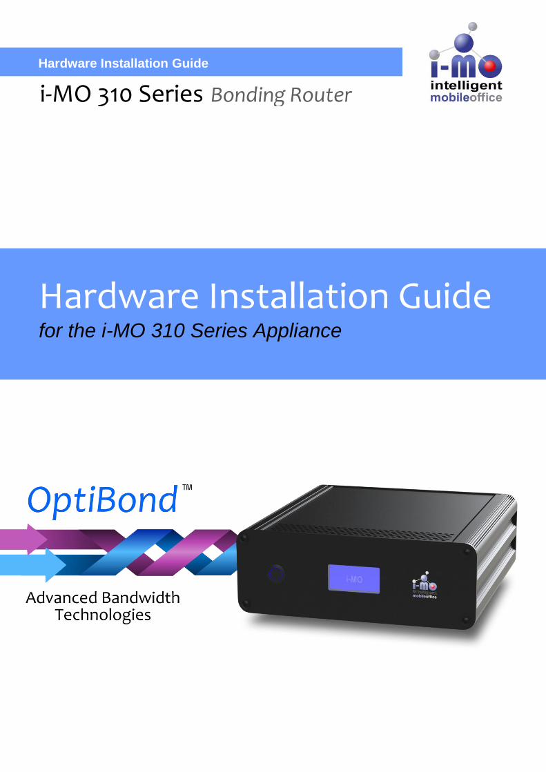
Hardware Installation Guide
i-MO 310 Series Bonding Router
Hardware Installation Guide
for the i-MO 310 Series Appliance
EMS i-MO 310 Series Hardware Installation Guide Version 2.0
ELECTRONIC MEDIA SERVICES LIMITED
PASSFIELD BUSINESS CENTRE, LYNCHBOROUGH ROAD, LIPHOOK, HAMPSHIRE, GU30 7SB, UK
Tel: 01428 751655 | Fax: 01428 751654 | E-mail: [email protected]
Page 2 of 19
Content
Content .............................................................................................................................................................. 2
I-MO Appliance Identification Guide .................................................................................................................. 4
General Safety Guidelines for EMS Hardware Equipment ................................................................................ 5
Installation Safety Guidelines and Warnings ..................................................................................................... 5
Operating Temperature Warning ................................................................................................................... 5
Product Disposal Warning ............................................................................................................................. 6
General Electrical Safety Warnings for EMS Hardware Equipment .................................................................. 6
Radio Frequency Interference ....................................................................................................................... 6
Electromagnetic Compatibility ....................................................................................................................... 6
AC Power Electrical Safety Guidelines .......................................................................................................... 6
Hardware Installation Guide .............................................................................................................................. 7
1) Attach WiFi antennas (optional) ................................................................................................................ 7
2) Attach 3G / 4G antennas and cables ........................................................................................................ 7
3) Attach network cables (optional) ............................................................................................................... 8
4) Install SIM cards ........................................................................................................................................ 8
5) Power cable ............................................................................................................................................... 9
6) Power switch ............................................................................................................................................. 9
7) Status display .......................................................................................................................................... 11
Appendix A - WiFi Radio Component .............................................................................................................. 12
Warnings ...................................................................................................................................................... 12
Regulatory Notices ...................................................................................................................................... 12
FCC ID: N7N-MHS802 ................................................................................................................................ 12
Certification Information (SAR) .................................................................................................................... 13
Technical Data ............................................................................................................................................. 13
Safety Regulation and Operating Environment ........................................................................................... 13
WiFi Radio Aerial ......................................................................................................................................... 14
Appendix B - Optional 3G / 4G Radio Component .......................................................................................... 15
External Installation ..................................................................................................................................... 15
Safety ................................................................................................................................................... 15
Choosing a Mounting Location ............................................................................................................ 16
Mounting the Antennas ........................................................................................................................ 16
Connecting the External Antennas to the i-MO ................................................................................... 16
Appendix C - Disposal and Recycling Information .......................................................................................... 17
WEEE EU Directive ..................................................................................................................................... 17
Reduction of Hazardous Substances .......................................................................................................... 17
Appendix D - Warranty Information ................................................................................................................. 18
EMS i-MO 310 Series Hardware Installation Guide Version 2.0
ELECTRONIC MEDIA SERVICES LIMITED
PASSFIELD BUSINESS CENTRE, LYNCHBOROUGH ROAD, LIPHOOK, HAMPSHIRE, GU30 7SB, UK
Tel: 01428 751655 | Fax: 01428 751654 | E-mail: [email protected]
Page 3 of 19
EMS's Limited Warranty Statement (1-Year Warranty) ............................................................................... 18
One-Year Limited Warranty ................................................................................................................. 18
Obtaining Technical Assistance ...................................................................................................................... 19
EMS i-MO 310 Series Hardware Installation Guide Version 2.0
ELECTRONIC MEDIA SERVICES LIMITED
PASSFIELD BUSINESS CENTRE, LYNCHBOROUGH ROAD, LIPHOOK, HAMPSHIRE, GU30 7SB, UK
Tel: 01428 751655 | Fax: 01428 751654 | E-mail: [email protected]
Page 4 of 19
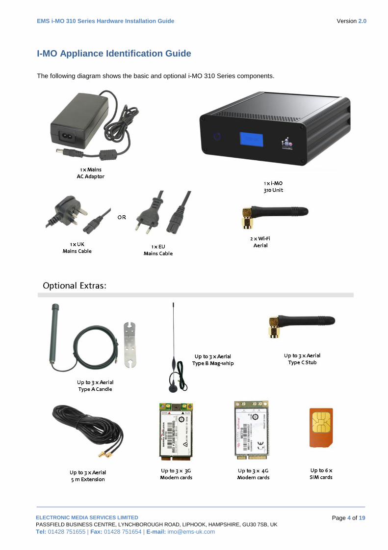
I-MO Appliance Identification Guide
The following diagram shows the basic and optional i-MO 310 Series components.
EMS i-MO 310 Series Hardware Installation Guide Version 2.0
ELECTRONIC MEDIA SERVICES LIMITED
PASSFIELD BUSINESS CENTRE, LYNCHBOROUGH ROAD, LIPHOOK, HAMPSHIRE, GU30 7SB, UK
Tel: 01428 751655 | Fax: 01428 751654 | E-mail: [email protected]
Page 5 of 19
General Safety Guidelines for EMS Hardware Equipment
The following guidelines help ensure your safety and protect the hardware equipment from damage. The list
of guidelines might not address all potentially hazardous situations in your working environment, so be alert
and exercise good judgment at all times.
Perform only the procedures explicitly described in this documentation. Make sure that only
authorized service personnel perform other system services.
Keep the area around the chassis clear and free from dust before, during, and after installation.
Keep tools away from areas where people could trip over them while walking.
Wear safety glasses if you are working under any conditions that could be hazardous to your eyes.
Do not perform any actions that create a potential hazard to people or make the equipment unsafe.
Never install or manipulate wiring during electrical storms.
Never install electrical jacks in wet locations unless the jacks are specifically designed for wet
environments.
Operate the hardware equipment only when the chassis is properly grounded.
Do not open or remove chassis covers or sheet metal parts unless instructions are provided in this
documentation. Such an action could cause severe electrical shock.
Do not push or force any objects through any opening in the chassis frame. Such an action could
result in electrical shock or fire.
Avoid spilling liquid onto the chassis or onto any hardware component. Such an action could cause
electrical shock or damage the hardware equipment.
Do not use the device where inflammables or explosives are stored, for example, in a fuel station, oil
depot, or chemical plant. Otherwise, explosions or fires may occur.
Use only the accessories supplied or authorized by the device manufacturer. Otherwise, the
performance of the device may get affected, the warranty for the device or the laws and regulations
related to telecommunications terminals may become null and void, or an injury may occur.
Do not use the power adapter if its cable is damaged. Otherwise, electric shocks or fires may occur.
Do not use the antennas if the connectors, cables, or antennas are damaged. Otherwise, radio
frequency interference or electric shock may occur.
Installation Safety Guidelines and Warnings
Read the installation instructions before you connect the hardware equipment to a power source.
Operating Temperature Warning
To prevent the hardware equipment from overheating, do not operate it in an area that exceeds the
maximum recommended ambient temperature of 40°C. To prevent airflow restriction, allow at least 2 inches
of clearance around the rear ventilation grille.
Do not expose to direct sunlight.
EMS i-MO 310 Series Hardware Installation Guide Version 2.0
ELECTRONIC MEDIA SERVICES LIMITED
PASSFIELD BUSINESS CENTRE, LYNCHBOROUGH ROAD, LIPHOOK, HAMPSHIRE, GU30 7SB, UK
Tel: 01428 751655 | Fax: 01428 751654 | E-mail: [email protected]
Page 6 of 19
Do not place containers of liquids on the device or allow the device to come in contact with liquids.
Do not place near or on a source of heat.
Product Disposal Warning
Disposal of this product must be handled according to all national laws and regulations.
See Appendix C for details.
General Electrical Safety Warnings for EMS Hardware Equipment
Radio Frequency Interference
You can reduce or eliminate the emission of radio frequency interference (RFI) from your site wiring by using
twisted-pair network cabling with a good distribution of grounding conductors. If you must exceed the rec-
ommended distances, use a high-quality twisted-pair cable with one ground conductor for each data signal
when applicable.
Electromagnetic Compatibility
If your site is susceptible to problems with electromagnetic compatibility (EMC), particularly from lightning or
radio transmitters, you might want to seek expert advice. Strong sources of electromagnetic interference
(EMI) can destroy the signal drivers and receivers in the router and conduct power surges over the lines into
the equipment, resulting in an electrical hazard. It is particularly important to provide a properly grounded
and shielded environment and to use electrical surge-suppression devices.
AC Power Electrical Safety Guidelines
The i-MO 310 Series appliance requires an AC supply of 100-240Volts, 50/60Hz and can draw a current of
up to 2 Amps.
i-MO routers are shipped with a three-wire electrical cord with a grounding-type plug that fits only a ground-
ing-type power outlet. Do not circumvent this safety feature. Equipment grounding should comply with local
and national electrical codes. The power cord serves as the main disconnecting device. The socket outlet
must be near the router and be easily accessible.
EMS i-MO 310 Series Hardware Installation Guide Version 2.0
ELECTRONIC MEDIA SERVICES LIMITED
PASSFIELD BUSINESS CENTRE, LYNCHBOROUGH ROAD, LIPHOOK, HAMPSHIRE, GU30 7SB, UK
Tel: 01428 751655 | Fax: 01428 751654 | E-mail: [email protected]
Page 7 of 19
Hardware Installation Guide
Electronic copies of this guide can be found by clicking this link: i-MO Documentation or by entering this
URL: http://tinyurl.com/lt297hl
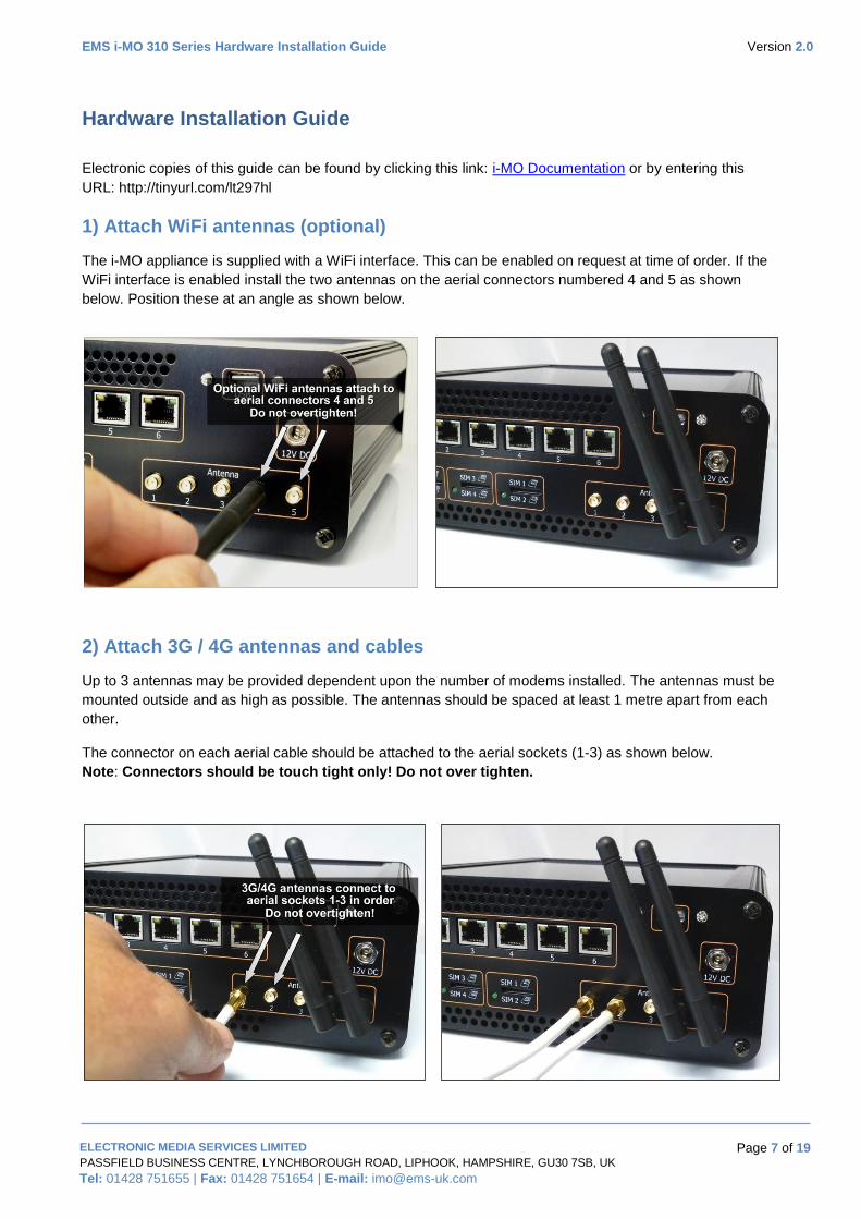
1) Attach WiFi antennas (optional)
The i-MO appliance is supplied with a WiFi interface. This can be enabled on request at time of order. If the
WiFi interface is enabled install the two antennas on the aerial connectors numbered 4 and 5 as shown
below. Position these at an angle as shown below.
2) Attach 3G / 4G antennas and cables
Up to 3 antennas may be provided dependent upon the number of modems installed. The antennas must be
mounted outside and as high as possible. The antennas should be spaced at least 1 metre apart from each
other.
The connector on each aerial cable should be attached to the aerial sockets (1-3) as shown below.
Note: Connectors should be touch tight only! Do not over tighten.
EMS i-MO 310 Series Hardware Installation Guide Version 2.0
ELECTRONIC MEDIA SERVICES LIMITED
PASSFIELD BUSINESS CENTRE, LYNCHBOROUGH ROAD, LIPHOOK, HAMPSHIRE, GU30 7SB, UK
Tel: 01428 751655 | Fax: 01428 751654 | E-mail: [email protected]
Page 8 of 19
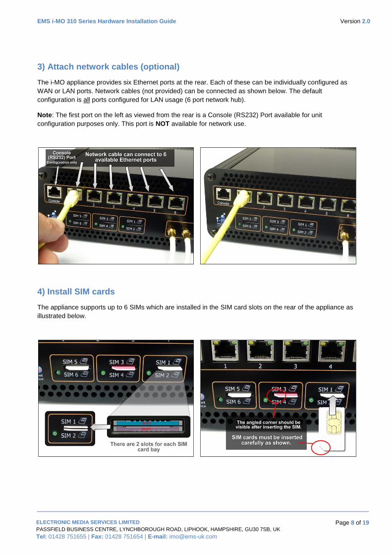
3) Attach network cables (optional)
The i-MO appliance provides six Ethernet ports at the rear. Each of these can be individually configured as
WAN or LAN ports. Network cables (not provided) can be connected as shown below. The default
configuration is all ports configured for LAN usage (6 port network hub).
Note: The first port on the left as viewed from the rear is a Console (RS232) Port available for unit
configuration purposes only. This port is NOT available for network use.
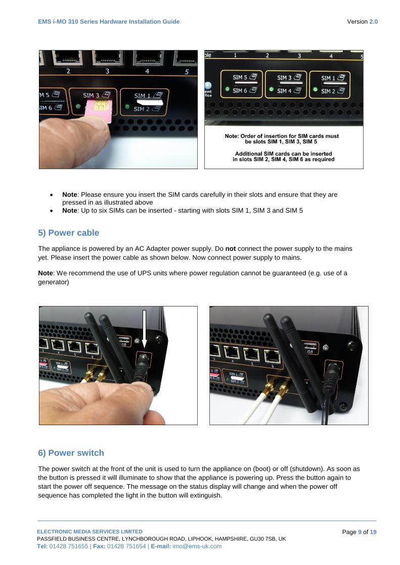
4) Install SIM cards
The appliance supports up to 6 SIMs which are installed in the SIM card slots on the rear of the appliance as
illustrated below.
EMS i-MO 310 Series Hardware Installation Guide Version 2.0
ELECTRONIC MEDIA SERVICES LIMITED
PASSFIELD BUSINESS CENTRE, LYNCHBOROUGH ROAD, LIPHOOK, HAMPSHIRE, GU30 7SB, UK
Tel: 01428 751655 | Fax: 01428 751654 | E-mail: [email protected]
Page 9 of 19
Note: Please ensure you insert the SIM cards carefully in their slots and ensure that they are pressed in as illustrated above
Note: Up to six SIMs can be inserted - starting with slots SIM 1, SIM 3 and SIM 5
5) Power cable
The appliance is powered by an AC Adapter power supply. Do not connect the power supply to the mains
yet. Please insert the power cable as shown below. Now connect power supply to mains.
Note: We recommend the use of UPS units where power regulation cannot be guaranteed (e.g. use of a
generator)
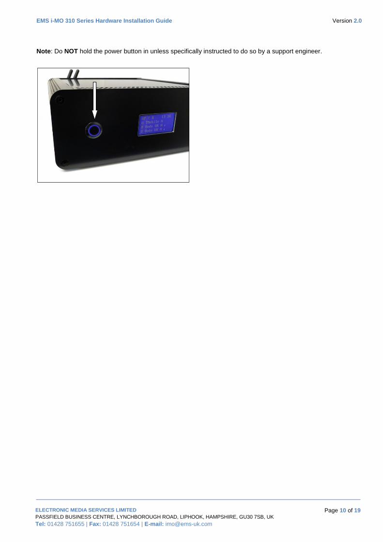
6) Power switch
The power switch at the front of the unit is used to turn the appliance on (boot) or off (shutdown). As soon as
the button is pressed it will illuminate to show that the appliance is powering up. Press the button again to
start the power off sequence. The message on the status display will change and when the power off
sequence has completed the light in the button will extinguish.
EMS i-MO 310 Series Hardware Installation Guide Version 2.0
ELECTRONIC MEDIA SERVICES LIMITED
PASSFIELD BUSINESS CENTRE, LYNCHBOROUGH ROAD, LIPHOOK, HAMPSHIRE, GU30 7SB, UK
Tel: 01428 751655 | Fax: 01428 751654 | E-mail: [email protected]
Page 10 of 19
Note: Do NOT hold the power button in unless specifically instructed to do so by a support engineer.
EMS i-MO 310 Series Hardware Installation Guide Version 2.0
ELECTRONIC MEDIA SERVICES LIMITED
PASSFIELD BUSINESS CENTRE, LYNCHBOROUGH ROAD, LIPHOOK, HAMPSHIRE, GU30 7SB, UK
Tel: 01428 751655 | Fax: 01428 751654 | E-mail: [email protected]
Page 11 of 19
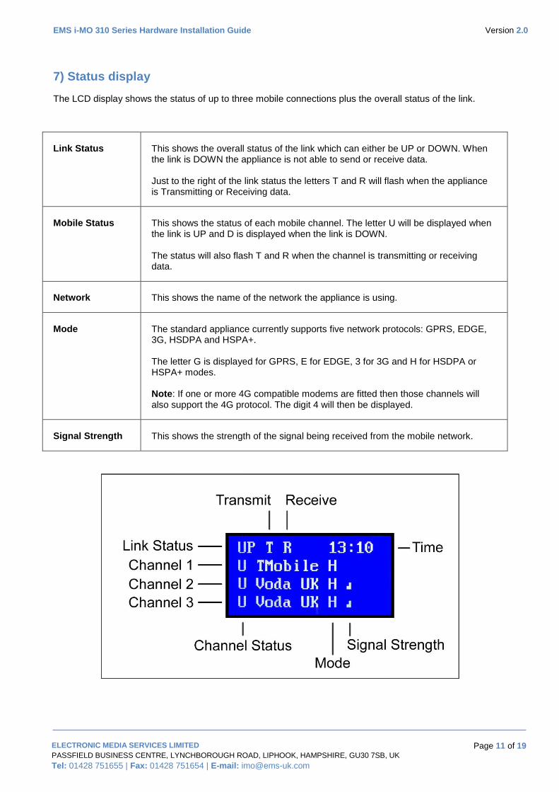
7) Status display
The LCD display shows the status of up to three mobile connections plus the overall status of the link.
Link Status This shows the overall status of the link which can either be UP or DOWN. When the link is DOWN the appliance is not able to send or receive data. Just to the right of the link status the letters T and R will flash when the appliance is Transmitting or Receiving data.
Mobile Status This shows the status of each mobile channel. The letter U will be displayed when the link is UP and D is displayed when the link is DOWN. The status will also flash T and R when the channel is transmitting or receiving data.
Network This shows the name of the network the appliance is using.
Mode The standard appliance currently supports five network protocols: GPRS, EDGE, 3G, HSDPA and HSPA+. The letter G is displayed for GPRS, E for EDGE, 3 for 3G and H for HSDPA or HSPA+ modes. Note: If one or more 4G compatible modems are fitted then those channels will also support the 4G protocol. The digit 4 will then be displayed.
Signal Strength This shows the strength of the signal being received from the mobile network.
EMS i-MO 310 Series Hardware Installation Guide Version 2.0
ELECTRONIC MEDIA SERVICES LIMITED
PASSFIELD BUSINESS CENTRE, LYNCHBOROUGH ROAD, LIPHOOK, HAMPSHIRE, GU30 7SB, UK
Tel: 01428 751655 | Fax: 01428 751654 | E-mail: [email protected]
Page 12 of 19
Appendix A - WiFi Radio Component
Warnings
When using the device, ensure that the antenna of the device is at least 1 cm away from all persons.
Do not use the device where using wireless devices is prohibited or may cause interference or danger.
Do not operate the WiFi device in areas where blasting is in progress, where explosive atmospheres may be
present, near medical equipment, life support equipment, or any equipment which may be susceptible to any
form of radio interference. In such areas, the WiFi device MUST BE POWERED OFF. It can transmit signals
that could interfere with this equipment.
Do not operate the WiFi device in any aircraft, whether the aircraft is on the ground or in flight. In aircraft, the
WiFi device MUST BE POWERED OFF. When operating, it can transmit signals that could interfere with
various on-board systems.
Regulatory Notices
The design of the WiFi device complies with U.S. Federal Communications Commission (FCC) guidelines
respecting safety levels of radio frequency (RF) exposure for mobile devices, which in turn are consistent
with the following safety standards previously set by U.S. and international standards bodies:
ANSI / IEEE C95.1-1999, IEEE Standard for Safety Levels with Respect to Human Exposure to
Radio Frequency Electromagnetic Fields, 3kHz to 300 GHz
National Council on Radiation Protection and Measurements (NCRP) Report 86, 1986, Biological
Effects and Exposure Criteria for Radio Frequency Electromagnetic Fields
International Commission on Non-Ionising Radiation Protection (ICNIRP) 1998, Guidelines for
limiting exposure to time-varying electric, magnetic, and electromagnetic fields (up to 300 GHz)
FCC ID: N7N-MHS802
RF Exposure - This device has been tested for compliance with FCC RF exposure limits in a portable
configuration. At least 1.0 cm of separation distance between the WiFi Antenna and the user's body must be
maintained at all times. This device must not be used with any other antenna or transmitter that has not been
approved to operate in conjunction with this device.
WARNING (EMI) - United States FCC Information - This equipment has been tested and found to comply
with the limits for a Class B computing device peripheral, pursuant to Parts 15 and 27 of the FCC rules.
These limits are designed to provide reasonable protection against harmful interference in a residential
installation.
This equipment generates, uses, and can radiate radio frequency energy. If not installed and used in
accordance with the instructions, it may cause harmful interference to radio communications. However, there
is no guarantee that interference will not occur in a particular installation.
If this equipment does cause harmful interference to radio or television reception, which can be determined
by turning the equipment off and on, the user is encouraged to try to correct the interference by one or more
of the following measures:
Reorient or relocate the receiving antenna.
Increase the separation between the equipment and receiver.
EMS i-MO 310 Series Hardware Installation Guide Version 2.0
ELECTRONIC MEDIA SERVICES LIMITED
PASSFIELD BUSINESS CENTRE, LYNCHBOROUGH ROAD, LIPHOOK, HAMPSHIRE, GU30 7SB, UK
Tel: 01428 751655 | Fax: 01428 751654 | E-mail: [email protected]
Page 13 of 19
Connect the equipment into an outlet on a circuit different from that to which the receiver is
connected.
Consult the dealer or an experienced radio/TV technician for help.
CAUTION: Any changes or modifications not expressly approved by EMS Ltd could void the user’s authority
to operate the equipment.
This device complies with Parts 15 and 27 of the FCC Rules. Operation is subject to the following two
conditions: (1) This device may not cause harmful interference, and (2) this device must accept any
interference received, including interference that may cause undesired operation.
Certification Information (SAR)
Your wireless device is a radio transmitter and receiver. It is designed not to exceed the limits for exposure to
radio waves recommended by international guidelines.
These guidelines are developed by the independent scientific organization International Commission on
Non-ionizing Radiation Protection (ICNIRP) and include safety margins designed to assure the protection of
all persons, regardless of age and health.
The guidelines use a unit of measurement known as the Specific Absorption Rate, or SAR. The SAR limit for
wireless devices is 2.0 watts/kilogram (W/kg) and the highest SAR value for this device when tested
complies with this limit.
Important safety information regarding radio frequency (RF) radiation exposure is as follows:
To ensure compliance with RF exposure guidelines, the device must be used with a minimum of 2.5cm
distance from the body. Failure to observe these instructions could result in your RF exposure exceeding the
relevant guideline limits.
Technical Data
2412 ~ 2472, 2484 MHz (subject to local regulations)
Modulation Technology OFDM and DSSS
Modulation Techniques 64QAM, 16QAM, QPSK, BPSK, CCK, DQPSK, DBPSK
Data Rates 54, 48, 36, 18,12, 9, 11, 6, 5.5, 2, and 1 Mbps, auto fallback
Peak Output Power Targeted at 14dBm @54Mbps, 18dBm @11Mbps
Minimum Receive Sensitivity Targeted at -70dBm @54Mbps; -80dBm@11Mbps
Antenna External antenna with the gain of 2dBi, L type
Safety Regulation and Operating Environment
FCC Part 15 (USA) DGT (Taiwan)
EMC certification
CE (Europe)
Temperature Range Operating: 0 ~ 40 degree C,
Storage: -20 ~ 65 degree C
EMS i-MO 310 Series Hardware Installation Guide Version 2.0
ELECTRONIC MEDIA SERVICES LIMITED
PASSFIELD BUSINESS CENTRE, LYNCHBOROUGH ROAD, LIPHOOK, HAMPSHIRE, GU30 7SB, UK
Tel: 01428 751655 | Fax: 01428 751654 | E-mail: [email protected]
Page 14 of 19
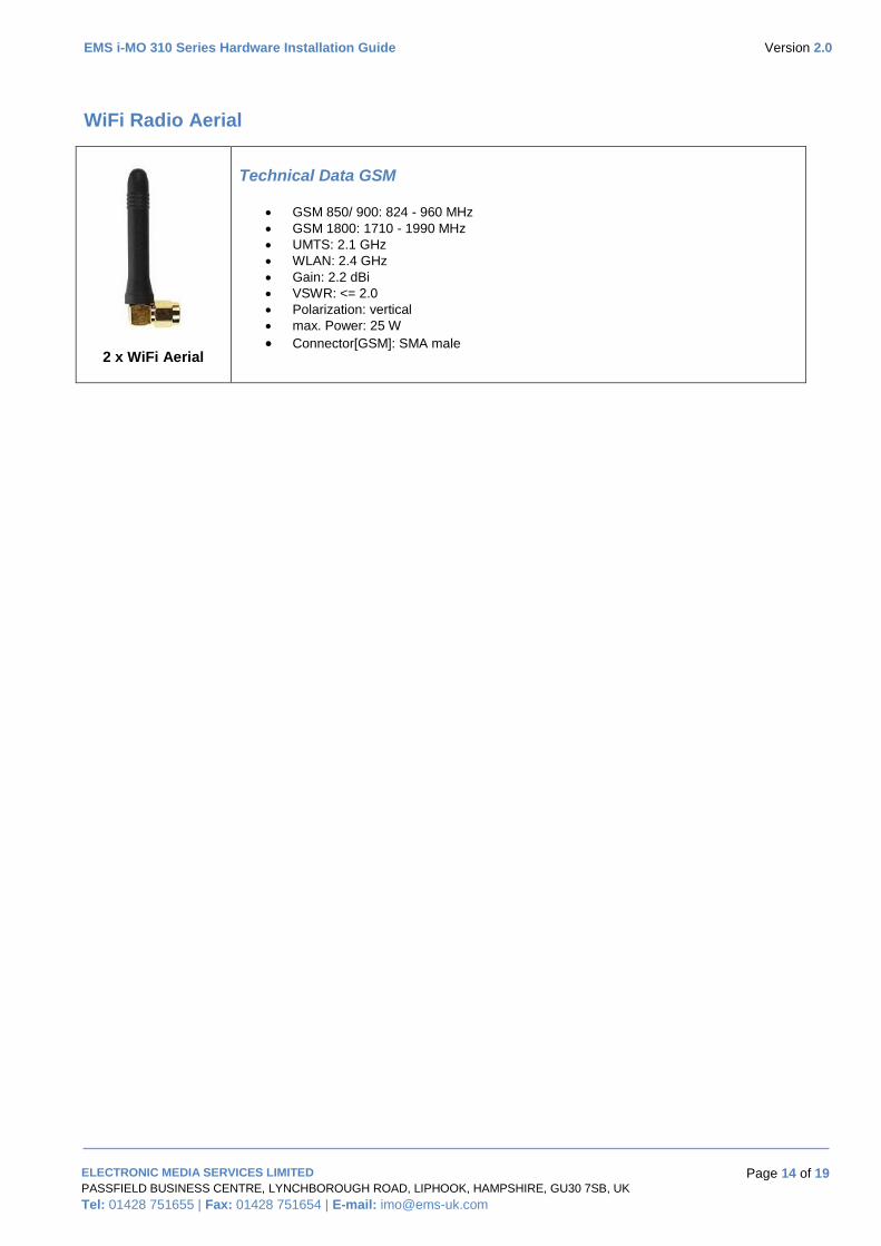
WiFi Radio Aerial
2 x WiFi Aerial
Technical Data GSM
GSM 850/ 900: 824 - 960 MHz
GSM 1800: 1710 - 1990 MHz
UMTS: 2.1 GHz
WLAN: 2.4 GHz
Gain: 2.2 dBi
VSWR: <= 2.0
Polarization: vertical
max. Power: 25 W
Connector[GSM]: SMA male
EMS i-MO 310 Series Hardware Installation Guide Version 2.0
ELECTRONIC MEDIA SERVICES LIMITED
PASSFIELD BUSINESS CENTRE, LYNCHBOROUGH ROAD, LIPHOOK, HAMPSHIRE, GU30 7SB, UK
Tel: 01428 751655 | Fax: 01428 751654 | E-mail: [email protected]
Page 15 of 19
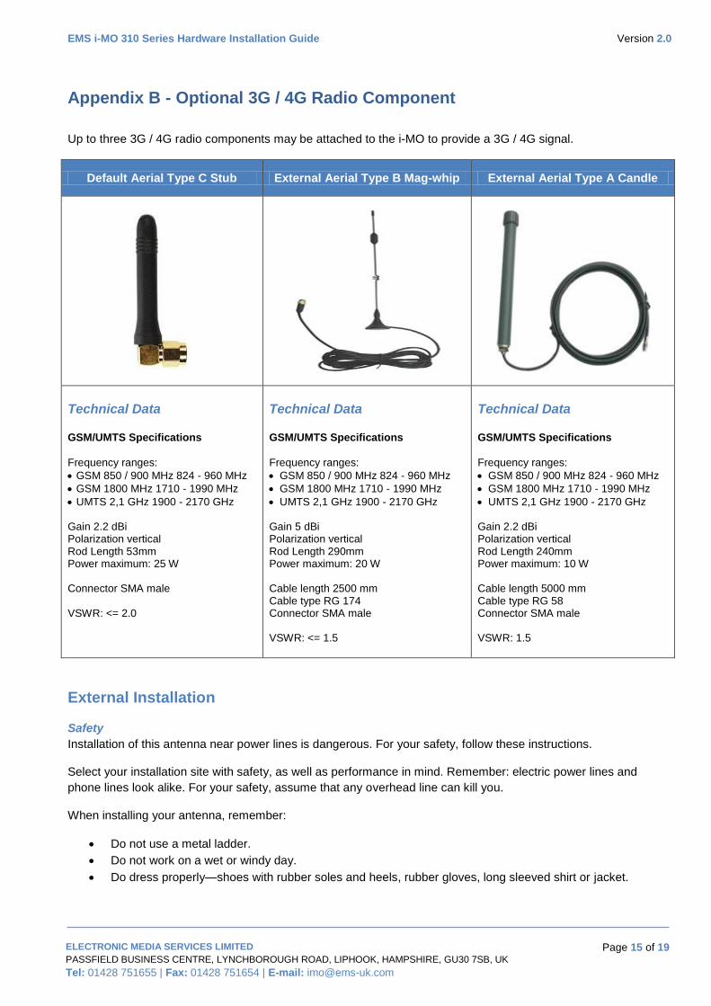
Appendix B - Optional 3G / 4G Radio Component
Up to three 3G / 4G radio components may be attached to the i-MO to provide a 3G / 4G signal.
Default Aerial Type C Stub External Aerial Type B Mag-whip External Aerial Type A Candle
Technical Data GSM/UMTS Specifications
Frequency ranges:
GSM 850 / 900 MHz 824 - 960 MHz
GSM 1800 MHz 1710 - 1990 MHz
UMTS 2,1 GHz 1900 - 2170 GHz Gain 2.2 dBi Polarization vertical Rod Length 53mm Power maximum: 25 W Connector SMA male VSWR: <= 2.0
Technical Data GSM/UMTS Specifications
Frequency ranges:
GSM 850 / 900 MHz 824 - 960 MHz
GSM 1800 MHz 1710 - 1990 MHz
UMTS 2,1 GHz 1900 - 2170 GHz Gain 5 dBi Polarization vertical Rod Length 290mm Power maximum: 20 W Cable length 2500 mm Cable type RG 174 Connector SMA male VSWR: <= 1.5
Technical Data GSM/UMTS Specifications
Frequency ranges:
GSM 850 / 900 MHz 824 - 960 MHz
GSM 1800 MHz 1710 - 1990 MHz
UMTS 2,1 GHz 1900 - 2170 GHz Gain 2.2 dBi Polarization vertical Rod Length 240mm Power maximum: 10 W Cable length 5000 mm Cable type RG 58 Connector SMA male VSWR: 1.5
External Installation
Safety
Installation of this antenna near power lines is dangerous. For your safety, follow these instructions.
Select your installation site with safety, as well as performance in mind. Remember: electric power lines and
phone lines look alike. For your safety, assume that any overhead line can kill you.
When installing your antenna, remember:
Do not use a metal ladder.
Do not work on a wet or windy day.
Do dress properly—shoes with rubber soles and heels, rubber gloves, long sleeved shirt or jacket.
EMS i-MO 310 Series Hardware Installation Guide Version 2.0
ELECTRONIC MEDIA SERVICES LIMITED
PASSFIELD BUSINESS CENTRE, LYNCHBOROUGH ROAD, LIPHOOK, HAMPSHIRE, GU30 7SB, UK
Tel: 01428 751655 | Fax: 01428 751654 | E-mail: [email protected]
Page 16 of 19
If any part of the antenna system should come in contact with a power line, don’t touch it or try to remove it
yourself. Call your local power company. They will remove it safely. If an accident should occur with the
power lines call for qualified emergency help immediately.
Choosing a Mounting Location
The location of the antenna is important. Objects such as metal columns, walls, etc. will reduce efficiency.
Best performance is achieved when antennas are mounted at the same height and in a direct line of sight
with no obstructions. If this is not possible and reception is poor, you should try different mounting positions
to optimize reception.
The antenna is designed to create an omni-directional broadcast pattern. To achieve this pattern, the
antenna should be mounted clear of any obstructions to the sides of the radiating element. If the mounting
location is on the side of a building or tower, the antenna pattern will be degraded on the building or tower
side.
Before attempting to install your antenna, think where you can best place the antenna for safety and
performance. Install your antenna at about 8 to 10 feet above the ground and away from all power lines and
obstructions.
Mounting the Antennas
The antennas should be mounted externally and as high as possible but ensure they are clear of any power
lines. The antennas should be spaced about 1 metre apart. The antenna is vertically polarized. Since the
antenna has vertical gain, it is very important to mount the antenna in a vertical (not leaning) position for
optimal performance.
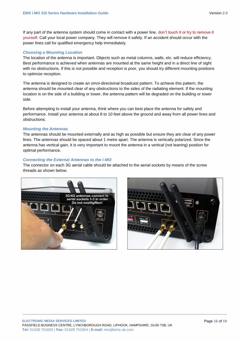
Connecting the External Antennas to the i-MO
The connector on each 3G aerial cable should be attached to the aerial sockets by means of the screw
threads as shown below.
EMS i-MO 310 Series Hardware Installation Guide Version 2.0
ELECTRONIC MEDIA SERVICES LIMITED
PASSFIELD BUSINESS CENTRE, LYNCHBOROUGH ROAD, LIPHOOK, HAMPSHIRE, GU30 7SB, UK
Tel: 01428 751655 | Fax: 01428 751654 | E-mail: [email protected]
Page 17 of 19
Appendix C - Disposal and Recycling Information
This device (and any included batteries) should not be disposed of as normal household garbage. Do not
dispose of your device or batteries as unsorted municipal waste. The device (and any batteries) should be
handed over to a certified collection point for recycling or proper disposal at the end of their life.
For more detailed information about the recycling of the device or batteries, contact your local city office, the
household waste disposal service, or the retail store where you purchased this device.
WEEE EU Directive
The disposal of this device is subject to the Waste from Electrical and Electronic Equipment (WEEE)
directive of the European Union. The reason for separating WEEE and batteries from other waste is to
minimize the potential environmental impacts on human health of any hazardous substances that may be
present.
If in any doubt, please view detailed WEEE information on the following web page from the Environment
Agency's web site:
http://www.environment-agency.gov.uk/business/topics/waste/32084.aspx
Reduction of Hazardous Substances
This device is compliant with the EU Registration, Evaluation, Authorisation and Restriction of Chemicals
(REACH) Regulation (Regulation No 1907/2006/EC of the European Parliament and of the Council) and the
EU Restriction of Hazardous Substances (RoHS) Directive (Directive 2002/95/EC of the European
Parliament and of the Council). For more information about the REACH compliance of the device, visit the
Web site www.ems-uk corn/certification. You are recommended to visit the Web site regularly for up-to-date
information.
EMS i-MO 310 Series Hardware Installation Guide Version 2.0
ELECTRONIC MEDIA SERVICES LIMITED
PASSFIELD BUSINESS CENTRE, LYNCHBOROUGH ROAD, LIPHOOK, HAMPSHIRE, GU30 7SB, UK
Tel: 01428 751655 | Fax: 01428 751654 | E-mail: [email protected]
Page 18 of 19
Appendix D - Warranty Information
EMS's Limited Warranty Statement (1-Year Warranty)
Thank you for purchasing the enclosed i-MO Appliance. The product is provided with a one year limited
warranty commencing from the date of purchase.
One-Year Limited Warranty
THIS PRODUCT IS PROVIDED TO YOU UNDER THE FOLLOWING TERMS AND CONDITIONS THAT
CONTAIN LIMITATIONS ON WARRANTIES AND LIABILITIES AND YOUR REMEDIES. BY USING THIS
PRODUCT YOU AGREE TO THE TERMS AND CONDITIONS BELOW.
The original end-user purchaser of the enclosed i-MO Appliance (the “Product”) from EMS Ltd (the “Vendor”)
or one of its authorized Partners, is offered with a non-transferable, limited warranty that: (a) the Product will
be of good quality and free from defects in design, materials, workmanship, and manufacture under normal
use and service; (b) all materials, parts, components, and other items incorporated in the Product will be
new; and (c) the Product will be compliant with, and perform in accordance with, its specifications, for a
period that expires one year from the original purchase date of the Product (the “Warranty Period”).
During the Warranty Period, if Vendor determines that a Product is defective under a proper warranty claim,
then Vendor will, at its sole discretion, either (a) pay parts and labour charges for the repair of the Product, or
(b) replace the Product with a new or rebuilt unit (which unit may use refurbished parts of similar quality and
functionality), provided that the defective Product is returned to a Vendor-authorized service centre for the
Product, transportation charges prepaid, and is accompanied by written proof of purchase in the form of a bill
of sale or receipted invoice indicating that the Product was purchased by you and is within the Warranty
Period. After the Warranty Period, you are responsible for paying all parts, labour, and shipping charges. The
warranty described above shall apply to all repaired or replaced Product for a period of 90 days from the
date of return to you, or the balance of the Warranty Period, whichever is greater.
This limited warranty does not cover and is void with respect to: (a) Products which have been improperly
installed, repaired, maintained, or modified; (b) Products which have been subjected to misuse (including
using the Products with hardware which is electrically or mechanically incompatible with the Products),
abuse, accident, physical damage, abnormal operation, improper handling or storage, neglect, exposure to
fire, water, or excessive moisture or dampness, or extreme changes in climate or temperature; (c) Products
which have been opened, repaired, modified, or altered by anyone other than Vendor or a Vendor-authorized
service centre; (d) Products which have been damaged due to fire, flood, acts of God, or other acts which
are not Vendor’s fault and which the Product is not specified to tolerate; (e) cosmetic damage; (f) Products
which have been operated outside of published maximum ratings; (g) cost of installation, removal, or
re-installation of the Product; (h) signal reception problems (unless caused by a defect in material(s) or
workmanship); or (i) Products on which warranty stickers or serial numbers have been removed, altered, or
rendered illegible. This limited warranty is not transferable to any third party including, but not limited to, any
subsequent purchaser or owner of the Products. Any transfer or resale of any of the Products will
automatically terminate Vendor’s warranty coverage of such Products. This limited warranty does not cover
customer education, instruction, installation, set-up adjustments, or signal reception problems.
REPAIR OR REPLACEMENT, AS PROVIDED FOR UNDER THIS LIMITED WARRANTY, IS YOUR SOLE
AND EXCLUSIVE REMEDY FOR BREACH OF THIS LIMITED WARRANTY. TO THE EXTENT
PERMITTED BY APPLICABLE LAW, NEITHER VENDOR NOR THE ORIGINAL OWNER OF THE
PRODUCT MAKE ANY OTHER REPRESENTATIONS, WARRANTIES, OR CONDITIONS OF ANY KIND,
EXPRESS OR IMPLIED OR STATUTORY, WITH RESPECT TO THE PRODUCT INCLUDING, BUT NOT
LIMITED TO, ANY WARRANTY OF MERCHANTABLE QUALITY, OR FITNESS FOR A PARTICULAR
PURPOSE.

EMS i-MO 310 Series Hardware Installation Guide Version 2.0
ELECTRONIC MEDIA SERVICES LIMITED
PASSFIELD BUSINESS CENTRE, LYNCHBOROUGH ROAD, LIPHOOK, HAMPSHIRE, GU30 7SB, UK
Tel: 01428 751655 | Fax: 01428 751654 | E-mail: [email protected]
Page 19 of 19
This warranty gives you specific rights and you may also have other rights, which vary from jurisdiction to
jurisdiction. Some jurisdictions do not allow the exclusion of implied warranties and conditions and do not
permit the exclusion or limitation of certain damages. Therefore, the foregoing exclusions may not apply to
you.
THE ENTIRE RISK AS TO THE RESULTS AND PERFORMANCE OF THIS PRODUCT IS ASSUMED BY
YOU. NEITHER THE ORIGINAL OWNER OF THE PRODUCT NOR THE VENDOR NOR VENDOR’S
DISTRIBUTORS, RESELLERS, SUPPLIERS, AGENTS, OFFICERS, AND DIRECTORS SHALL HAVE ANY
LIABILITY TO YOU OR TO ANY OTHER PERSON OR ENTITY FOR ANY DAMAGES HOWSOEVER
CAUSED INCLUDING, BUT NOT LIMITED TO, DIRECT, INDIRECT, INCIDENTAL, SPECIAL, GENERAL,
CONSEQUENTIAL, PUNITIVE, OR EXEMPLARY DAMAGES WHATSOEVER INCLUDING, BUT NOT
LIMITED TO, LOSS OF REVENUE OR PROFIT, DAMAGES TO PROPERTY OR PERSONS, LOST OR
DAMAGED DATA, OR OTHER COMMERCIAL OR ECONOMIC LOSS, EVEN IF ANY SUCH
AFOREMENTIONED PERSON HAS BEEN ADVISED OF THE POSSIBILITY OF SUCH DAMAGES OR
THEY ARE FORESEEABLE, OR FOR CLAIMS BY ANY THIRD PARTY. MAXIMUM AGGREGATE
LIABILITY OF THE AFOREMENTIONED PERSONS SHALL NOT EXCEED THE AMOUNT PAID BY YOU
FOR THE PRODUCT. THE LIMITATIONS IN THIS SECTION SHALL APPLY WHETHER OR NOT THE
ALLEGED BREACH, DEFAULT, NONPERFORMANCE, OR FAILURE IS A BREACH OF FUNDAMENTAL
CONDITION OR TERM, OR A FUNDAMENTAL BREACH.
If any provision or term of these terms and conditions is determined to be invalid or unenforceable, the
invalidity or un-enforceability of that provision or term will not affect the validity or enforceability of the
remaining provisions and terms or the validity or enforceability of that provision or term in any other
jurisdiction.
THIS LIMITED WARRANTY IS NOT AN ALTERNATIVE TO THE PURCHASE OF AN ANNUAL
MAINTENANCE AGREEMENT. For further details of Annual Maintenance Agreement Terms & Conditions
please refer to the separate Maintenance Agreement documentation provided by EMS Ltd or Authorised
Partner.
Obtaining Technical Assistance
EMS Ltd provides www.ems-imo.com as a starting point for all technical assistance. Customers and partners
can obtain documentation, troubleshooting tips, and sample configurations from online tools by using this
Web Site. Registered users (requires a valid Annual Maintenance Agreement) have complete access to the
technical support resources on the www.ems-imo.com Web Site.


![Wiring RS-485 · PDF fileHardware Installation Guidelines KeyMaster Systems Wiring RS-485 Networks Revision A 2002-12-16 [RS-485 HIG Rev A ENG-US] Building security solutions](https://img.pdfslide.us/doc/110x75/5a7668f57f8b9a1b688d348f/wiring-rs-485-networks-a-hardware-installation-guidelines-keymaster-systems.jpg)