Embed Size (px)
Citation preview

INSTALLATION MANUAL
APPLICATION:
FA C09 095G (95gph @ 10psi)FA C09 150G (150gph @ 10psi)
Duramax 2500 & 3500
2001-2012
3
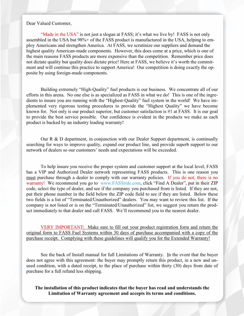
Dear Valued Customer,
“Made in the USA” is not just a slogan at FASS; it’s what we live by! FASS is not only
assembled in the USA but 98%+ of the FASS product is manufactured in the USA, helping to em-
ploy Americans and strengthen America. At FASS, we scrutinize our suppliers and demand the
highest quality American-made components. However, this does come at a price, which is one of
the main reasons FASS products are more expensive than the competition. Remember price does
not dictate quality but quality does dictate price! Here at FASS, we believe it’s worth the commit-
ment and will continue this practice to support America! Our competition is doing exactly the op-
posite by using foreign-made components.
Building extremely “High-Quality” fuel products is our business. We concentrate all of our
efforts in this arena. No one else is as specialized as FASS in what we do! This is one of the ingre-
dients to insure you are running with the “Highest-Quality” fuel system in the world! We have im-
plemented very rigorous testing procedures to provide the “Highest Quality” we have become
known for. Not only is our product superior, but customer satisfaction is #1 at FASS. It is our goal
to provide the best service possible. Our confidence is evident in the products we make as each
product is backed by an industry leading warranty!
Our R & D department, in conjunction with our Dealer Support department, is continually
searching for ways to improve quality, expand our product line, and provide superb support to our
network of dealers so our customers’ needs and expectations will be exceeded.
To help insure you receive the proper system and customer support at the local level, FASS
has a VIP and Authorized Dealer network representing FASS products. This is one reason you
must purchase through a dealer to comply with our warranty policies. If you do not, there is no
warranty! We recommend you go to www.FASSride.com, click “Find A Dealer”, put in their ZIP
code, select the type of dealer, and see if the company you purchased from is listed. If they are not,
put their phone number in the field below the ZIP code field to see if they are listed. Below these
two fields is a list of “Terminated/Unauthorized” dealers. You may want to review this list. If the
company is not listed or is on the “Terminated/Unauthorized” list, we suggest you return the prod-
uct immediately to that dealer and call FASS. We’ll recommend you to the nearest dealer.
VERY IMPORTANT: Make sure to fill out your product registration form and return the
original form to FASS Fuel Systems within 30 days of purchase accompanied with a copy of the
purchase receipt. Complying with these guidelines will qualify you for the Extended Warranty!
See the back of Install manual for full Limitations of Warranty. In the event that the buyer
does not agree with this agreement: the buyer may promptly return this product, in a new and un-
used condition, with a dated receipt, to the place of purchase within thirty (30) days from date of
purchase for a full refund less shipping.
The installation of this product indicates that the buyer has read and understands the
Limitation of Warranty agreement and accepts its terms and conditions.
4
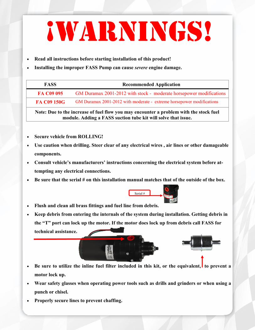
FASS Recommended Application
FA C09 095 GM Duramax 2001-2012 with stock - moderate horsepower modifications
FA C09 150G GM Duramax 2001-2012 with moderate - extreme horsepower modifications
Note: Due to the increase of fuel flow you may encounter a problem with the stock fuel
module. Adding a FASS suction tube kit will solve that issue.
Serial #
¡WARNINGS!
Read all instructions before starting installation of this product!
Installing the improper FASS Pump can cause severe engine damage.
Secure vehicle from ROLLING!
Use caution when drilling. Steer clear of any electrical wires , air lines or other damageable
components.
Consult vehicle’s manufacturers’ instructions concerning the electrical system before at-
tempting any electrical connections.
Be sure that the serial # on this installation manual matches that of the outside of the box.
Flush and clean all brass fittings and fuel line from debris.
Keep debris from entering the internals of the system during installation. Getting debris in
the “T” port can lock up the motor. If the motor does lock up from debris call FASS for
technical assistance.
Be sure to utilize the inline fuel filter included in this kit, or the equivalent, to prevent a
motor lock up.
Wear safety glasses when operating power tools such as drills and grinders or when using a
punch or chisel.
Properly secure lines to prevent chaffing.

5
(FA C09 095G or FA C09 150G)
(FA C09 095G or FA C09 150G)
INSTALLATION MANUAL
Follow these steps to ensure a simple installation of your new
FASS ADJUSTABLE FUEL PUMP
1. Read the installation manual completely before attempting installation. The instal-
lation of this product indicates that the buyer has read and understands the limita-
tions of the FASS manufacturers warranty agreement and accepts the responsibility
of its terms and conditions.
2. Inventory the package components. Notify the place of purchase immediately of
any parts missing or damaged.
3. The installation recommendations contained herein are guidelines. Use good judg-
ment and take into consideration your vehicles' accessories.
4. For best results in accuracy and efficiency (due to training, communication, and our
relationship with our dealer network), we recommend an Authorized or ViP FASS
Fuel Systems dealer for the installation. They are prepared to install the FASS fuel
pumps with the most efficiency. If a situation/problem arises during the installation,
they are the most prepared for that situation/problem. DPPI is not responsible for
any installation mistakes.
5. If you have any questions or concerns that can not be addressed with your dealer,
email or call FASS.
6. If any installation procedure is uncertain, contact FASS technical support.
Email [email protected] with the following information:
Your Name, address and daytime phone number
Model
Serial Number
Last 6 of vehicles’ VIN
Date of purchase
Nature of Your Concern
Call customer service; 636-433-5410 with the following information:
Model
Serial Number
Last 6 of vehicles’ VIN
Date of purchase
Serial # Found

6
95 or 150 GPH
10 PSI (Approximately)
Adjustable Fuel Pump Series
A fuel pressure gauge is highly recommended to identify fuel filter life and to prevent engine damage!
“E”
To Engine
‘T’
Fuel Inlet Port
Boost
Compensation
Port
Fuel Pressure Port
Adjustment Lock Nut
Set screw
Installation
Step 1: Install Electrical Harness
Step 2: Prepare Suction & Return Lines
Step 3: Mount Fuel System
Step 4: Install Fuel Line
Step 5: Check/Set Pressure
Step 5: Check Installation
7
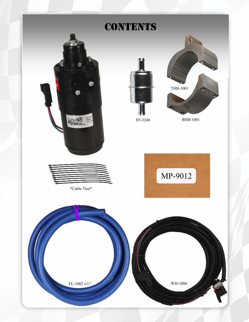
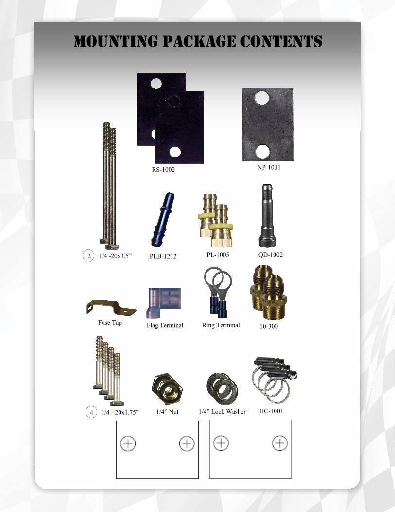
Contents
FL-1002 x11’ WH-1006
MP-9012
BHB-1001
THB-1001
FF-3248
*Cable Ties*
8
10-300
PL-1005
1/4” Nut 1/4” Lock Washer
NP-1001 RS-1002
4 1/4 - 20x1.75”
Fuse Tap Flag Terminal
Mounting Package Contents
QD-1002
HC-1001
Ring Terminal
PLB-1212 2 1/4 -20x3.5”

9
e. Route WH-1006 wire harness along frame rail to mounting location of pump. Completion of this step
will be addressed in the Mounting Step 3.
The installation of the electrical harness is done first, allowing power to be applied to the pump for
lubrication purposes later in the installation.
a. Disconnect battery before beginning installation. Crimp the ring termi-
nals to the red and green wires of the WH-1006 Wire Harness. The use
of a corrosion preventative on electrical connections is recom-
mended. Attach red wire to the positive terminal of the battery and the
green terminal to the negative terminal.
c. Guide the single red wire from the relay through the fire wall grommet to
the fuse panel.
d. Connect the fuse tap to the hot side of the fuse. Use a test probe to
locate the “hot side” of the circuit in the fuse block. Using the fuse tap
& flag terminal, connect the red lead to a terminal on the circuit board
b. Secure relay and fuse in an upright position, as shown, to prevent mois-
ture from entering. Di-electric grease may be applied to prevent corro-
sion.
FUSE
RELAY
10
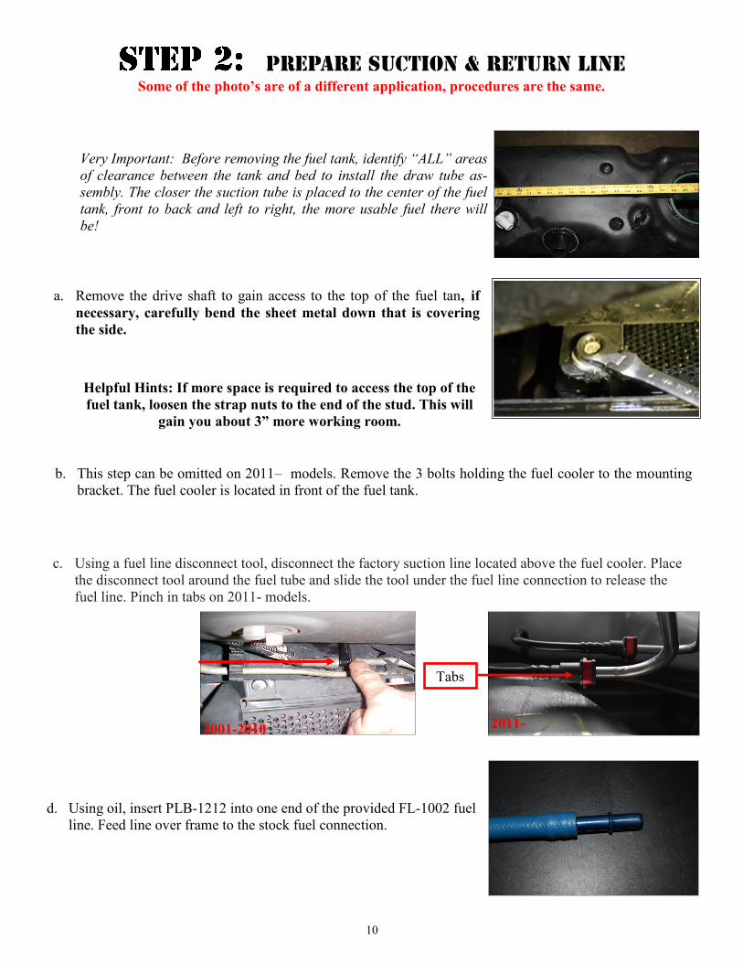
d. Using oil, insert PLB-1212 into one end of the provided FL-1002 fuel
line. Feed line over frame to the stock fuel connection.
Very Important: Before removing the fuel tank, identify “ALL” areas
of clearance between the tank and bed to install the draw tube as-
sembly. The closer the suction tube is placed to the center of the fuel
tank, front to back and left to right, the more usable fuel there will
be!
a. Remove the drive shaft to gain access to the top of the fuel tan, if
necessary, carefully bend the sheet metal down that is covering
the side.
Some of the photo’s are of a different application, procedures are the same.
c. Using a fuel line disconnect tool, disconnect the factory suction line located above the fuel cooler. Place
the disconnect tool around the fuel tube and slide the tool under the fuel line connection to release the
fuel line. Pinch in tabs on 2011- models.
2001-2010
Tabs
2011-
Helpful Hints: If more space is required to access the top of the
fuel tank, loosen the strap nuts to the end of the stud. This will
gain you about 3” more working room.
b. This step can be omitted on 2011– models. Remove the 3 bolts holding the fuel cooler to the mounting
bracket. The fuel cooler is located in front of the fuel tank.

11
f. Using an HC-1001 hose clamp, insert the QD-1002 into the other end of the provided FL-1002 fuel line
and secure. Loop this end over the frame to the factory steel fuel line disconnected in Step 2b. Oil the rings
inside the QD-1002 and slide over the line until you hear a click. Do not cut the line at this time.
2001-2010 2011-
e. Push the PLB-1212 into the factory suction line until you hear a click and the tabs are locked in place.
2001-2010 2011-
12
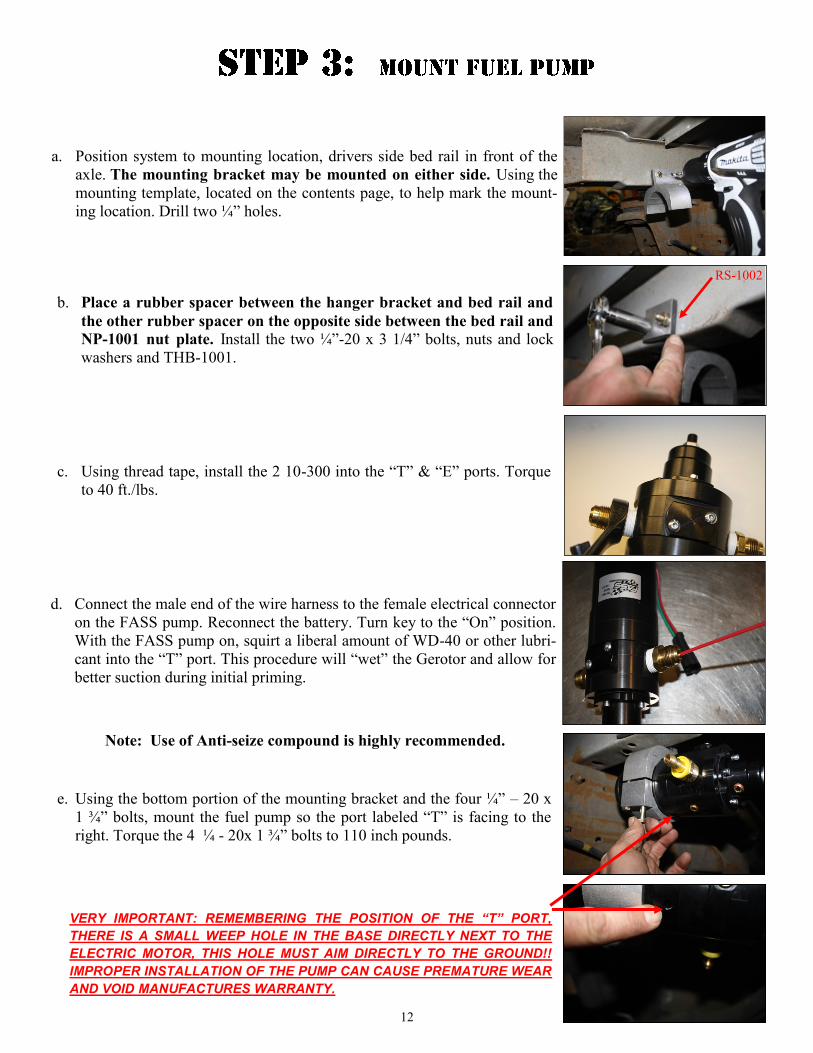
a. Position system to mounting location, drivers side bed rail in front of the
axle. The mounting bracket may be mounted on either side. Using the
mounting template, located on the contents page, to help mark the mount-
ing location. Drill two ¼” holes.
c. Using thread tape, install the 2 10-300 into the “T” & “E” ports. Torque
to 40 ft./lbs.
b. Place a rubber spacer between the hanger bracket and bed rail and
the other rubber spacer on the opposite side between the bed rail and
NP-1001 nut plate. Install the two ¼”-20 x 3 1/4” bolts, nuts and lock
washers and THB-1001.
VERY IMPORTANT: REMEMBERING THE POSITION OF THE “T” PORT,
THERE IS A SMALL WEEP HOLE IN THE BASE DIRECTLY NEXT TO THE
ELECTRIC MOTOR, THIS HOLE MUST AIM DIRECTLY TO THE GROUND!!
IMPROPER INSTALLATION OF THE PUMP CAN CAUSE PREMATURE WEAR
AND VOID MANUFACTURES WARRANTY.
d. Connect the male end of the wire harness to the female electrical connector
on the FASS pump. Reconnect the battery. Turn key to the “On” position.
With the FASS pump on, squirt a liberal amount of WD-40 or other lubri-
cant into the “T” port. This procedure will “wet” the Gerotor and allow for
better suction during initial priming.
e. Using the bottom portion of the mounting bracket and the four ¼” – 20 x
1 ¾” bolts, mount the fuel pump so the port labeled “T” is facing to the
right. Torque the 4 ¼ - 20x 1 ¾” bolts to 110 inch pounds.
Note: Use of Anti-seize compound is highly recommended.
RS-1002
13
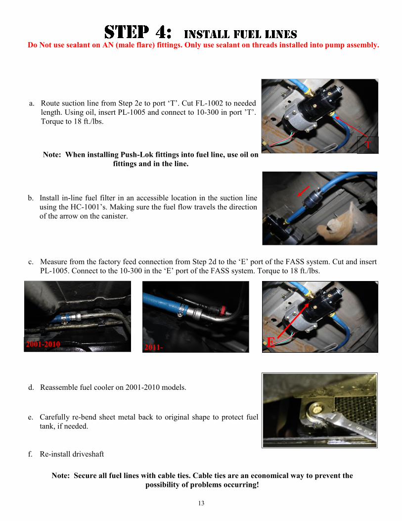
a. Route suction line from Step 2e to port ‘T’. Cut FL-1002 to needed
length. Using oil, insert PL-1005 and connect to 10-300 in port ’T’.
Torque to 18 ft./lbs.
T
Do Not use sealant on AN (male flare) fittings. Only use sealant on threads installed into pump assembly.
Note: When installing Push-Lok fittings into fuel line, use oil on
fittings and in the line.
b. Install in-line fuel filter in an accessible location in the suction line
using the HC-1001’s. Making sure the fuel flow travels the direction
of the arrow on the canister.
c. Measure from the factory feed connection from Step 2d to the ‘E’ port of the FASS system. Cut and insert
PL-1005. Connect to the 10-300 in the ‘E’ port of the FASS system. Torque to 18 ft./lbs.
E 2001-2010 2011-
e. Carefully re-bend sheet metal back to original shape to protect fuel
tank, if needed.
f. Re-install driveshaft
d. Reassemble fuel cooler on 2001-2010 models.
Note: Secure all fuel lines with cable ties. Cable ties are an economical way to prevent the
possibility of problems occurring!
14
The preset pressure is approximately 10 psi. Follow these steps to check or reset the fuel pressure. The port
with 1/8” Allen plug marked with the letter “P” is your fuel pressure port. Exceeding factory fuel pressure
may result in severe engine damage. Consult with engine manufacture before adjusting pressure!
With the pump running –
Loosen the lock nut
Turn the adjustment screw clock wise to increase pressure and counter clock wise to decrease pressure.
Once desired fuel pressure is obtained, tighten lock nut.
Blow out any open lines/cover any open ports
Bolts and fasteners properly tightened?
Electrical harness and fuel lines secured and properly tightened? Reconnect the battery.
Has the system been primed?
1. Turn key to the ignition position, turning on the FASS pump for 15 sec..
2. Crank engine and allow to run for at least 1 minute.
Check for leaks.
Start the engine
Recheck all fluid and filter connections for leaks
This pump comes with a 1 Year Manufacturer’s Warranty based on the date it has been manufactured. To
receive your extended Lifetime Warranty, you have 30 days from date of purchase to send the completed
warranty information along with a copy of the purchase receipt in to Diesel Performance Products, Inc.
Att: Warranty 16240 Hwy O Suite B Marthasville, MO 63357

15
Disclaimer: To help insure you receive the proper system and customer support at the local level, FASS has a VIP and Authorized Dealer network representing FASS products. This is one reason you must purchase through a dealer to comply with our warranty policies. If you do not, there is no warranty! We recommend you go to www.FASSride.com, click “Find a Dealer”, put in their ZIP code, select the type of dealer, and see if the company you purchased from is listed. If they are not, put their phone number in the field below the ZIP code field to see if they are listed. Below these two fields is a list of “Terminated/Unauthorized” dealers. You may want to review this list. If the company is not listed or is on the “Terminated/Unauthorized” list, we suggest you return the product immediately to that dealer and call FASS. We’ll recom-mend you to the nearest dealer.
Diesel Performance Products, Inc. (hereafter “SELLER”) gives Limited Warranty as to description, quality, merchantabil-
ity, fitness for any product’s purpose, productiveness, or any other matter of SELLER’S product sold herewith. The
SELLER shall be in no way responsible for the product’s open use and service and the BUYER hereby waives all rights
other than those expressly written herein. This Warranty shall not be extended or varied except by a written instrument
signed by SELLER and BUYER.
When MANUFACTURER receives the “ORIGINAL” PRODUCT REGISTRATION form with a copy of the “BILL
OF SALE/SALES RECEIPT” within 30 days of the sale, then the following applies! The Warranty will then and only
then be validated to that of which typically accompanies your unit for your specific application from the date of sale or for
recommended service life and limited solely to the original purchaser and/or vehicle and parts contained within the prod-
uct’s kit. This warranty does not cover normal wear on consumable items such as but not limited to filters, fuel line, wire
harness & etc. The warranty does not cover seized gears due to lack of filtration or fatty acid build up on the gears. Re-
turned items will arrive prepaid to the place of purchase. Diesel Performance Products, Inc. will repair, without cost, any
product found to be defective during the warranty period; parts only, or at its option, will replace such products in exchange
for the product. Repair or replacements are warranted for the remainder of the original warranty period. All Warranty
claims are subject to approval by Diesel Performance Products, Inc.
A Return Material Authorization (RMA) number must be obtained before any product is to be returned to Diesel
Performance Products, Inc. for warranty consideration, repair or product return. Requests for product returns must
be offset by an equal value order. Return parts must be completed and in resalable condition. No returns after 30 days.
The following information is required to obtain a RMA number before returning product:
Your Name, Address, and Phone Number’s Model and Serial Number (Not Motor Number) Example: Model HD Series, Serial: 00125966 VIN Number of Vehicle Date of Purchase Nature of Problem
RMA and Product Serial Number must be on all paperwork and correspondence. Failure to obtain the required information
or paperwork will result in $25.00/item penalty and delay or denial of any warranty claim.
Under no circumstances shall the SELLER and/or MANUFACTURER be liable for any labor charged or travel time in-
curred in diagnosis for defects, removal, or reinstallation of this product, or any other contingent expenses.
Under no circumstances shall the SELLER and/or MANUFACTURER be liable for any damage or expenses insured by
reason of the use or sale of any such equipment. This warranty does not apply to products which Diesel Performance Prod-
ucts, Inc. has determined to have been misused or abused, improperly maintained by the user, or where the malfunction or
defect can be attributed to the use of non-genuine Diesel Performance Products, Inc. parts.
IN THE EVENT THAT THE BUYER DOES NOT AGREE WITH THIS AGREEMENT: THE BUYER MAY PROMPLY
RETURN THIS PRODUCT, IN A NEW AND UNUSED CONDITION, WITH A DATED PROOF OF PURCHASE, TO
THE PLACE OF PURCHASE WITHIN THIRTY (30) DAYS FROM DATE OF PURCHASE FOR A FULL REFUND
LESS SHIPPING.
THE INSTALLATION OF THIS PRODUCT INDICATES THAT THE BUYER HAS READ AND UNDER-
STANDS THIS AGREEMENT AND ACCEPTS ITS TERMS AND CONDITIONS.
Technical Support:
Diesel Performance Products, Inc. 16240 State Hwy O Suite B
Marthasville, MO 63357
636-433-5410

16