Embed Size (px)
Citation preview
Hardware implementation of Configurable High data Rate Test Station for Data Handling System of Earth
Observation Satellites 1Sharmistha Sharma, 2Somasundaram.S, 3Ankit Agarwal, 4Thenmozhi Selvi
1 Manipal Centre for Information Science, Manipal University, Manipal, Karnataka, India. [email protected]
2,3,4Digital Systems Group, ISRO Satellite Centre, Bangalore, Karnataka, India. [email protected], [email protected], [email protected]
Abstract— Earth observation satellites are used to observe the earth surfaces, sea surfaces, analysis of anthropogenic effects on earth, earth imaging, climatic monitoring, ocean currents etc. The observation instruments are installed on satellites for remote sensing purposes. Major imaging observing instruments includes Panchromatic CCD/TDI cameras, multispectral CCD/TDI cameras and SAR payloads. A Satellite development involves rigorous testing before qualification. Qualification of satellite in turn involves a challenge of developing a robust, configurable and standardised test station to deliver flight qualified subsystems with zero defects for satellite applications. Developing such a test station for subsystems and usage across multiple satellite missions reduces the turn around time, cost of components, testing methods, overall spacecraft development schedule and increases the reliability of the subsystems. This paper addresses the design and development of a configurable test station that is suitable to test the Data handling system of multiple satellite missions. The paper includes the architecture of test station and necessary utilities required to qualify the entire base band data handling system. The paper also addresses the configurable/programmable hardware and software that allow reusing of different interfaces of the test system with other subsystems to meet multiple satellite missions. Keywords— Test Station, Image Simulator, BDH, Solid State Recorder, XBS interface, Playback interface, Configurable.
I. INTRODUCTION
Base band data handling (BDH) is one of the major subsystems in the payload data downlink chain in all the remote sensing satellite missions. It is a subsystem in satellite that has a role of accepting the raw image data from the payload generate the formatted transfer frame, Record the data in a solid state recorder and playback the data depending on the command received from ground. As the payload data rate to BDH increases, the complexity of realising the Data Handling System in hardware also increases.Until recently the test station for base band data handling systems had to be customized from mission to mission. This involves a huge process and support which is difficult. The test station for such a subsystem can also be standard and configurable. This
enables us to make low cost simulators for space systems. Operational Class of satellites consists of Payloads, Data Handling System with Recorder and Playback features, R-F System, etc. Here emphasis is given to test the base band data handling system with recorders and play back feature. The test station proposed here explains the architecture of simulators and the necessary software utilities to test the entire data handling system. The test station has all the features like System Initialization, Data Collection, Memory sequencing, Test sequencing, Data Simulation, Telemetry Display and Graphical User Interface. It is configurable and can simulate any image with pixel depth ranging from 7 bit to 16 bit. The total number of ports to be simulated is also configurable. Configuration Commands are issued via RS-232 to perform all the functions. It is also equipped with Record and playback interface to record formatted data into a PC, and playback the data to BDH system. The graphical user interface (GUI) acts as an interface between the Test system, PC and BDH system.
II. HARDWARE ARCHITECTURE OF TEST STATION
BDH has the flexibility to transmit the Transfer Frames to ground through R-F interface directly without any storage in the recorder. It has interfaces with Power, Payload, Solid State Recorder and XBS systems. Thus the testing of BDH requires the development of the various interface simulators. To check the functionalities, electrical interfaces and to highlight the system capabilities of BDH with other subsystems a complete test station is crucial. Both hardware and software support is required for the test station and here the architecture has come up with the maximum utilization of a PCB configuration which reduces the design and development time of interface simulators for the test stations. In different modes of operation data is simulated and transfer frames from BDH are acquired. The acquired data along with the telemetry is validated further. A. Interface details The test station requires a test set up for interfaces of BDH system with Image simulator, SSR simulator, XBS Simulator and Acquisition Unit. The BDH system accepts data from Image simulator through Serialiser/Deserialiser interface. The data is compressed, formatted to generate Transfer Frames. The data is directly fed to XBS simulator through LVDS
International Journal of Scientific & Engineering Research, Volume 4, Issue 6, June-2013 ISSN 2229-5518
1898
IJSER © 2013 http://www.ijser.org
IJSER
interface or recorded depending upon the mission requirement. While real time transfers, the data to XBS is transmitted as two chains whereas recording feature allows the formatted data transfer as four channels via SSR simulator through serialiser interface. It is further stored in PC. The playback interface takes the recorded data from the PC, transfers the data via BDH system to the XBS simulator. The Play back data reaching the BDH system from the SSR simulator is then encrypted, RS-encoded, randomized, differentially encoded and sent to the XBS interface. The data is acquired using a high speed PC based data acquisition system for data integrity check and validation. Thus all the interfaces to BDH system are verified and validated which in turn helps to qualify a flight worthy BDH system.
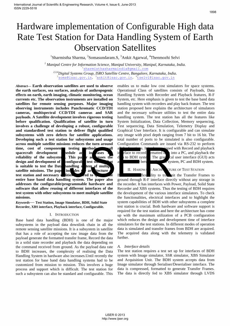
Fig1: Architecture of Test Station
The figure shows the hardware architecture of test station. The hardware architecture can be subdivided into the following modules: A. Logic level translator card:
Fig2: Level Translator Card
The logic level translator card receives 16 bit image, Commands and Clock from Console, converts into LVDS
signals and transfers to Image distribution card of test station. The Image distribution card transfers the image to all the image simulators. It has an FPGA, Crystal and RS232 I/F to generate commands required for the simulator. The Tele command and Telemetry interface for the test station is planned using RS232 protocol. The HDL code for RS232 module resides in the FPGA. The commands received via RS232 is first level translated and then fed to FPGA. The FPGA decodes the command by performing a serial to parallel conversion and distributes the commands to various simulators. Telemetry received from simulators is also decoded by the FPGA and transferred to GUI for display. B. Memory sequencing and image simulation card :
Fig3: Memory Sequencing and Image Simulation Card
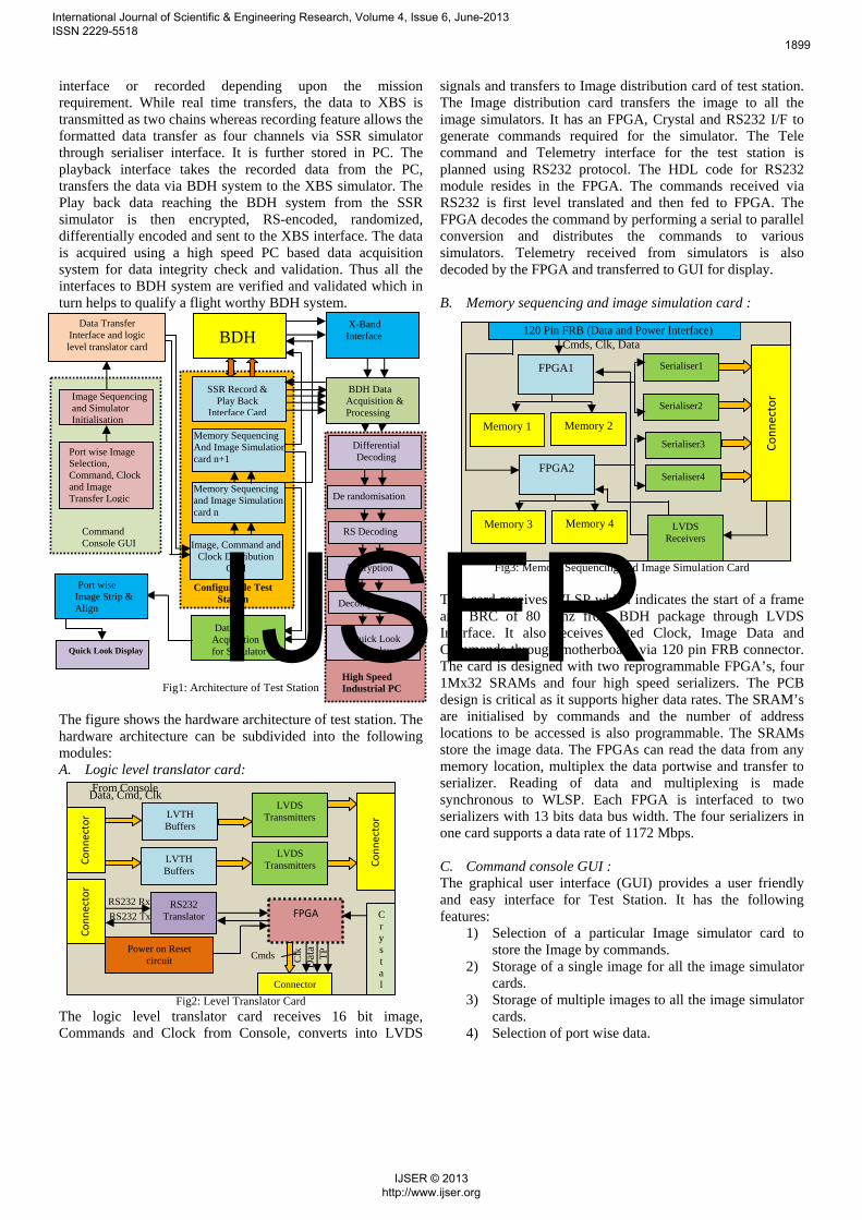
This card receives WLSP which indicates the start of a frame and BRC of 80 Mhz from BDH package through LVDS Interface. It also receives gated Clock, Image Data and Commands through motherboard via 120 pin FRB connector. The card is designed with two reprogrammable FPGA’s, four 1Mx32 SRAMs and four high speed serializers. The PCB design is critical as it supports higher data rates. The SRAM’s are initialised by commands and the number of address locations to be accessed is also programmable. The SRAMs store the image data. The FPGAs can read the data from any memory location, multiplex the data portwise and transfer to serializer. Reading of data and multiplexing is made synchronous to WLSP. Each FPGA is interfaced to two serializers with 13 bits data bus width. The four serializers in one card supports a data rate of 1172 Mbps. C. Command console GUI : The graphical user interface (GUI) provides a user friendly and easy interface for Test Station. It has the following features:
1) Selection of a particular Image simulator card to store the Image by commands.
2) Storage of a single image for all the image simulator cards.
3) Storage of multiple images to all the image simulator cards.
4) Selection of port wise data.
FPGA RS232
Translator
Connector
Cmds Clk
D
ata
TP
Crystal
Power on Reset circuit
RS232 Tx
RS232 Rx
Data, Cmd, Clk From Console
Connector
LVDS Transmitters
LVDS Transmitters
LVTH Buffers
Connector
LVTH Buffers
Connector
High Speed Industrial PC
Configurable Test Station
Command Console GUI
Memory Sequencing and Image Simulation card n
Port wise Image Selection, Command, Clock and Image Transfer Logic
Data Transfer Interface and logic level translator card
Image Sequencing and Simulator Initialisation
BDH
Image, Command and Clock Distribution
Card
SSR Record & Play Back
Interface Card
X-Band Interface
BDH Data Acquisition & Processing
Quick Look Display
Decompression
Differential Decoding
Decryption
RS Decoding
Data Acquisition for Simulator
Port wise Image Strip & Align
Quick Look Display
Memory Sequencing And Image Simulation card n+1
De randomisation
Serialiser1 FPGA1
Connector
FPGA2
120 Pin FRB (Data and Power Interface)
Memory 1 Memory 2
Memory 3 Memory 4
Serialiser2
Serialiser3
Serialiser4
LVDS Receivers
Cmds, Clk, Data
International Journal of Scientific & Engineering Research, Volume 4, Issue 6, June-2013 ISSN 2229-5518
1899
IJSER © 2013 http://www.ijser.org
IJSER
5) Issue of Memory sequencing commands. 6) Reset the address location of Memories. 7) Simulate the Image port wise for each payload. 8) Simulate all ports simultaneously for single payload. 9) Simulate all ports simultaneously for multiple
payloads.
Fig4: Command Console GUI
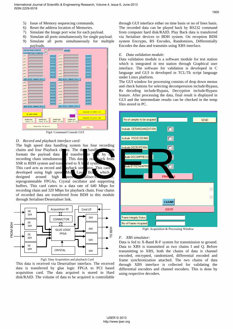
D. Record and playback interface card: The high speed data handling system has four recording chains and four Playback chains. The data handling system formats the payload data and transfers to SSR by this recording chain simultaneously. This data is read back from SSR to BDH system and transferred to X band system. This card acts as record and playback simulator. This card is developed using high speed Multi Layer Board which is designed around high speed Serialiser/Deserialiser, reprogrammable FPGAs, Crystal oscillator and supporting buffers. This card caters to a data rate of 640 Mbps for recording chain and 320 Mbps for playback chain. Four chains of recorded data are transferred from BDH to this module through Serialiser/Deserialiser link.
Fig5: Data Acquisition and playback Card
This data is received via Deserialiser interface. The received data is transferred by glue logic FPGA to PCI based acquisition card. The data acquired is stored in Hard disk/RAID. The volume of data to be acquired is controllable
through GUI interface either on time basis or no of lines basis. The recorded data can be played back by RS232 command from computer hard disk/RAID. Play Back data is transferred via Serialiser devices to BDH system. On reception BDH system Encrypts, RS Encodes, Randomizes, Differentially Encodes the data and transmits using XBS interface. E. Data validation module: Data validation module is a software module for test station which is integrated in test station through Graphical user interface. The software for validation is developed in C language and GUI is developed in TCL/Tk script language under Linux platform. The GUI window for processing consists of drop down menus and check buttons for selecting decompression include/Bypass, Rs decoding include/Bypass, Decryption include/Bypass feature. After processing the data, final result is displayed in GUI and the intermediate results can be checked in the temp files stored in PC.
Fig6: Acquisition & Processing Window
F. XBS simulator: Data is fed to X-Band R-F system for transmission to ground. Data to XBS is transmitted as two chains I and Q. Before transmitting to XBS, both the chains of data is channel encoded, encrypted, randomized, differential encoded and frame synchronization attached. The two chains of data through XBS interface is collected for validating the differential encoders and channel encoders. This is done by using respective decoders.
DE SER
DE SER
DE SER
DE SER
GLUE LOGICFPGA
CONNECTOR
CRYSTAL
SER
SER
SER
SER
FROM BDH
TO BDH
Cmd I/F Acquisition PC
International Journal of Scientific & Engineering Research, Volume 4, Issue 6, June-2013 ISSN 2229-5518
1900
IJSER © 2013 http://www.ijser.org
IJSER
III. HIGH SPEED PCB ARCHITECTURE
PCB design is carried out using FPGAs, memories, TTL, LVDS, Serialiser and Deserialiser devices etc. The placement of components and routing is done as per high speed digital design guidelines. Decoupling capacitors are provided as per design guidelines for the PCB. Power entry capacitors are used to provide filter effects and to avoid noise. To conduct the heat away from the high dissipating ICs, a separate Copper plane is provided in the PCB design.
IV. FLOW DIAGRAM OF SOFTWARE
Fig7: Flow Diagram
BDH system generates CCSDS transfer frames of fixed length with 4 bytes ASM and master and virtual channel count. CCSDS space packets which consists of compressed data or AUX data with header and APID information is inserted in these transfer fames. CCSDS space pkt has variable length of 7 bytes to 64K bytes.
Fig8: Transfer Frame Structure The acquired data is fed to frame integrity check module. The diagram in figure 7 is a representation of the software flow. Frame integrity module verifies correctness of ASM every fixed interval of time. ASM is stripped off from transfer frame and fed to de-randomization, RS-decoding and decryption module depending upon check button of GUI. The data is further fed to space packet extraction module where space packets are segregated APID wise. The space packets are fed to decompression module and after decompression quality of compression is measured by RMSE, PSNR parameter and the data integrity is verified and validated.
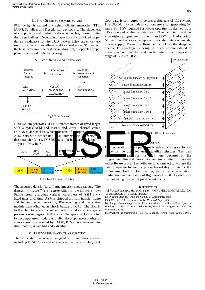
V. TEST SYSTEM PACKAGE REALISATION
The test system package is designed with configurable cards including DC-DC tray and motherboard as shown in Figure 9.
Each card is configured to deliver a data rate of 1172 Mbps. The DC-DC tray includes two converters for generating 5V and 3.3V. 1.5V required for FPGA operation is derived from LDO mounted on the daughter board. The daughter board has a provision to generate 3.3V with an LDO for load sharing. Mother board acts as a backplane to transfer data, commands, power supply, Power on Reset and clock to the daughter boards. This package is designed to get accommodated in thermo vacuum chamber and can be tested for a temperature range of -55ºC to +85ºC.
VI. CONCLUSION
The test station developed here is robust, configurable and hence can be used for many satellite missions. The turn around time and cost is very less because of the programmability and reusability features existing in the card and software reuse. The software is automated to acquire the data in separate folders for proper traceability of data for the future use. End to End testing, performance evaluation, verification and validation of flight model of BDH system can be done using this reconfigurable test station.
REFERENCES [1] Howard Johnson, Martin Graham, “HIGH SPEED DIGITAL DESIGN: A HANDBOOK OF BLACK MAGIC” [2] William Stallings, Data and Computer Communications. [3] CCSDS 1 33.0-B-I, Space Packet Protocol. Sept 2003. [4] Image Data Compression, Recommendation for Space Data Systems Standards, CCSDS 122.0-B-1, Blue Book, Issue 1. Washington D.C.: CCSDS, November, 2005. [5] Practical Programming in TCL/TK Language. Brent Welch, Jan 30, 1995.
ASM Primary Header
Space Packet unit
ASM Primary Header
Space Packet unit
APID SEQ. CNT
PKT LEN
Compressed Data and Aux Data
Transfer frame Integrity
RS Decoding Decryption
Space pkt extraction and validation
DE‐COMPRESSION
PSNR AND RMSE ERROR CALCULATION
DATA VALIDATION
DISPLAY RESULT
Fig9: Image Simulator Package with DC-DC and Connectors
Mother Board
Powering Module (DC-DC)
Data I/F and Command I/F Card
Image Simulation Card 1
Image Simulation Card 2
Image Simulation Card 3
Image Simulation Card n
Image Simulation Card n+1
SSR I/F Card (Record & Playback)
International Journal of Scientific & Engineering Research, Volume 4, Issue 6, June-2013 ISSN 2229-5518
1901
IJSER © 2013 http://www.ijser.org
IJSER


![MPC8548E Configurable Development System … Configurable Development System Reference Manual, ... [4:0] ... MPC8548E Configurable Development System Reference Manual,](https://img.pdfslide.us/doc/110x75/5af028337f8b9ac62b8e4c0e/mpc8548e-configurable-development-system-configurable-development-system-reference.jpg)